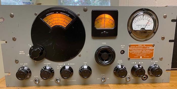
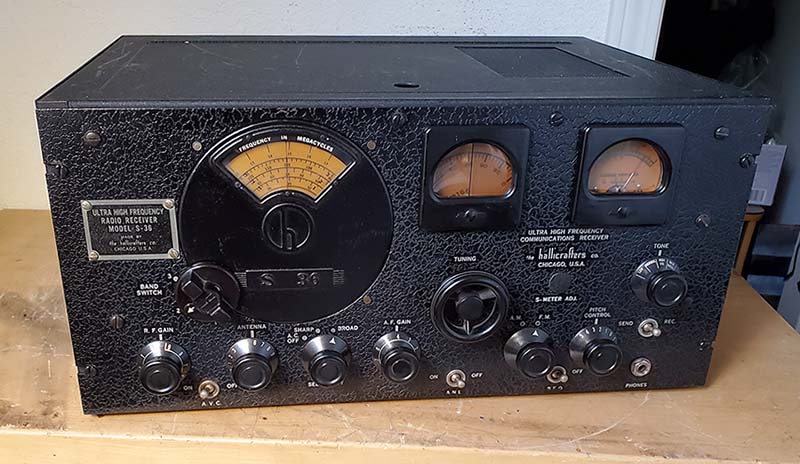
| It's possible that S-36 models used by the Army Signal
Corps won't have military data plates on them and are identified by
a metal Hallicrafters identification plate mounted to the left of
the dial bezel and the presence of Signal Corps acceptance stamps. It's
also likely that some S-36 models were used in
civilian government applications,...airports for instance where there
were a lot of VHF activities that had been going on since the
late-thirties (airport towers used both HF and VHF in the early forties, also
fan marker
beacons were on 75mc in the early-forties.) It's likely these models would
also have the Hallicrafters ID plate. The Hallicrafters ID
plate was eliminated on the S-36A and subsequent post-WWII versions. The following
are some of the identifying characteristics of the S-27, S-36 and S-36A.
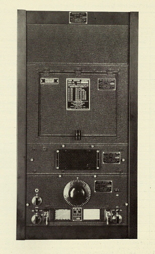
S-27 Model has IF tubes
shown as "industrial tubes" 1853 (6AB7), 1852 (6AC7) and the standard
6SK7, frame-type power transformer, two individual filter chokes in
power supply, filter capacitor is a standard round multi-section type
electrolytic mounted on top of the chassis, 6C8 dual triode for phase
inv/1st AF tube, the dial bezel will have S-27 embossed, the band switch
knob is a small round knob with a skirt, S-meter is illuminated and has
a yellow scale and is mounted behind the front panel with a small bezel,
500Z and 5000Z audio outputs only
(the S-27 is covered in Rider's XII.)
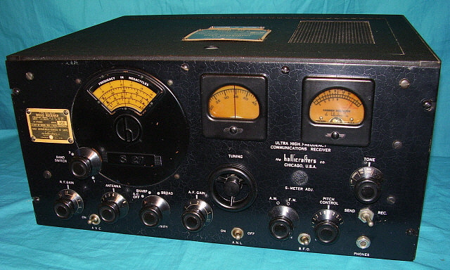
S-36 Model has IF tubes shown in the standard designation
as 6AB7, 6AC7 and 6SK7, frame type power transformer, two individual
filter chokes in power supply, filter capacitor is a square package
multi-section mounted on top of the chassis, early S-36 has the 6C8 tube but later
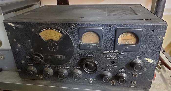
S-36 uses 6SL7 tube, early S-36 will still have "S-27" embossed on bezel and
band switch will be round knob with skirt, later S-36 will have "S-36"
embossed on dial bezel and will have the skirted bar knob on the band
switch, S-meter is
the illuminated, yellow scale type on most versions but very late
versions were fitted with a non-illuminated, white scale meter
that's mounted to the front side of the panel, two upper panel holes
(for cabinet) between main and logging dials and between logging dial
and S-meter, later S-36 will have a 600Z ohm balanced audio output line
at the phone jack on the front panel with terminals on the back chassis
apron with selectable grounded CT in addition to the 500Z and 5000Z
outputs (the S-36 is not covered in Rider's)
S-36A Model has same IF
tubes as non-A, uses a potted power transformer and a single unit dual filter choke that's mounted on top of
chassis, square multi-section filter capacitor, 6SL7 phase inv/1st AF tube, location of the two 6H6 tubes
changed, late versions will have "S-36A" embossed on dial bezel with
skirted bar knob for the band switch, non-illuminated white scale
S-meter mounted to the front of the panel (not the yellow scaled S-meter
mounted behind the panel and a small bezel as in the S-27 and
S-36), controls for AF gain, Tone, Send-Rec switch, BFO pitch relocated,
only one upper hole (for cabinet) between main dial and logging dial,
engraving ID moved from S-meter area to upper left panel area and metal
ID plate eliminated, advertising artwork shows that cinch-plug not used
to cover S-meter adjustment hole, the audio output includes a 600Z ohm
balanced output at the phone jack on the front panel with terminals on
the rear chassis apron for selectable grounded CT in addition to the
500Z and 5000Z outputs (the S-36A is covered in Rider's XV) Most of the engineering upgrades were
incorporated into the receivers as they were built on the production
line. It's common to find an early version of the receiver that has one
or some characteristics of the later version. Also, normal production methods would
generally result in most existing stock being used
up before new stock was installed on new production however intermixing
of stock was also common, so all versions of the receiver may have a few
characteristics of earlier or later versions. |
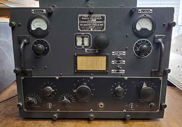
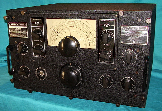
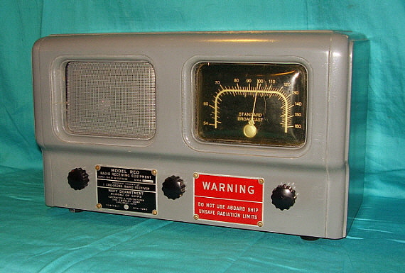
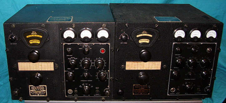
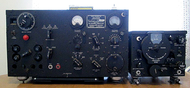
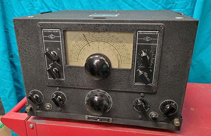
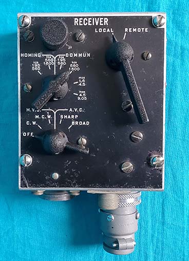
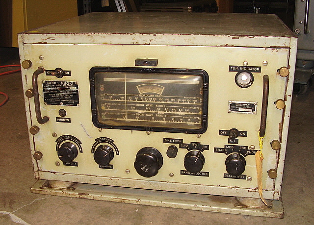
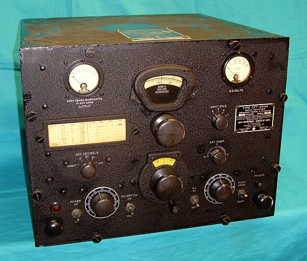 RBA-1
CFT-46154
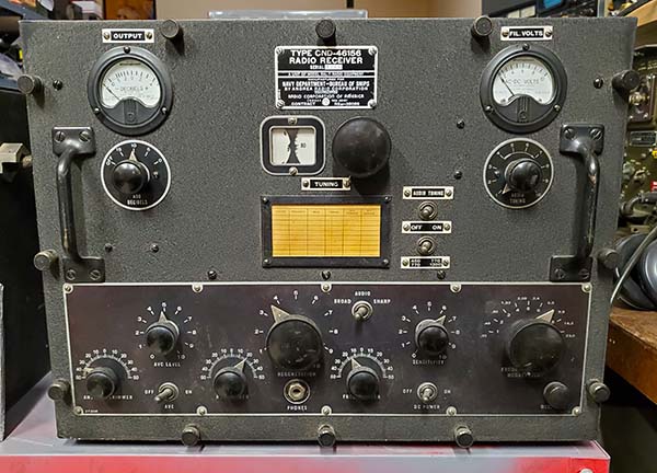
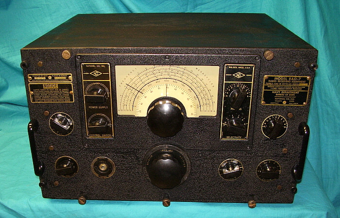
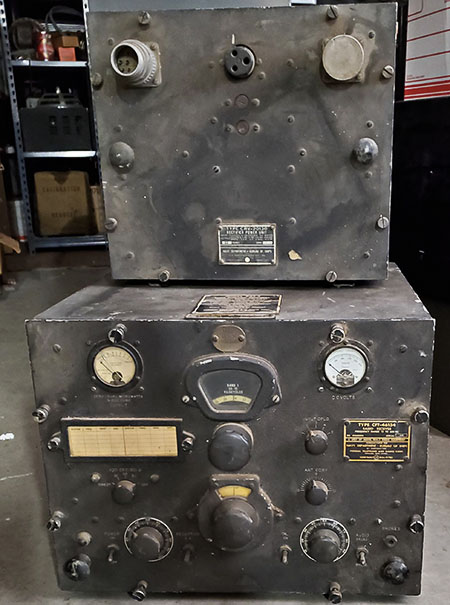
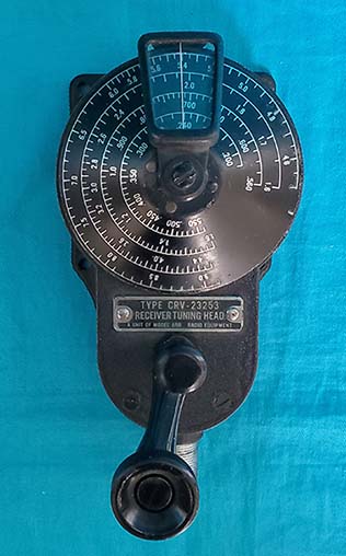
RBA-1
CFT-46154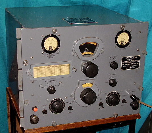

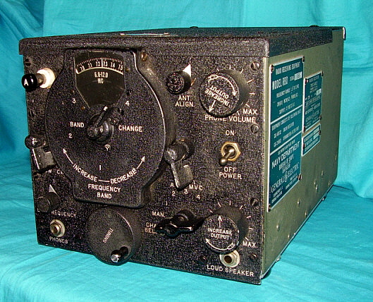
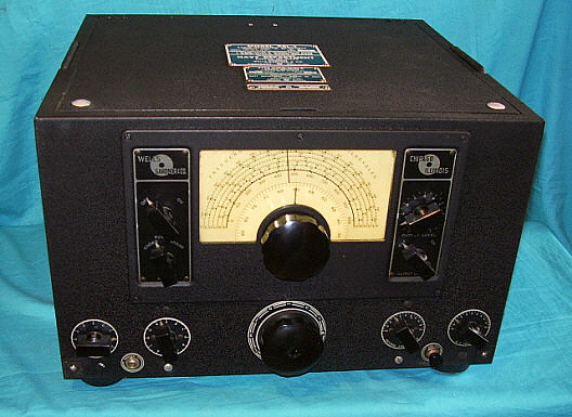


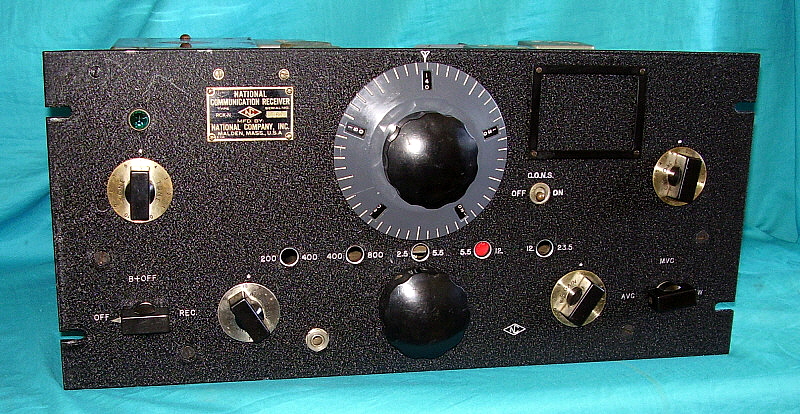
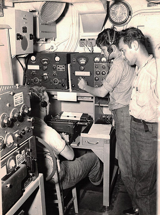
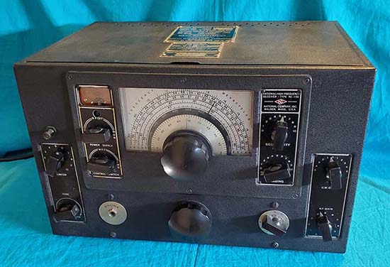
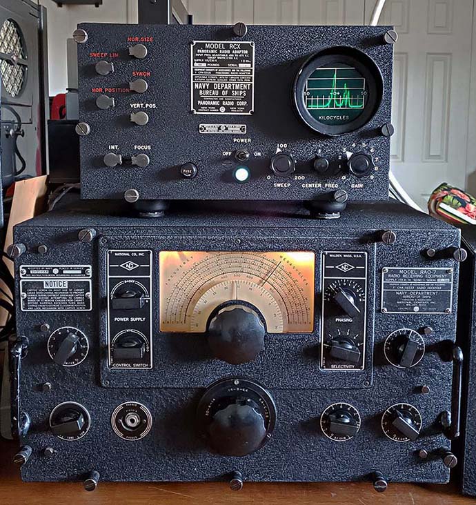
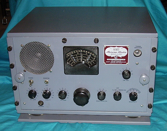
 SLR-F
Receiver with BFO
SLR-F
Receiver with BFO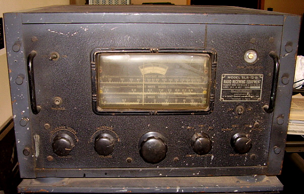
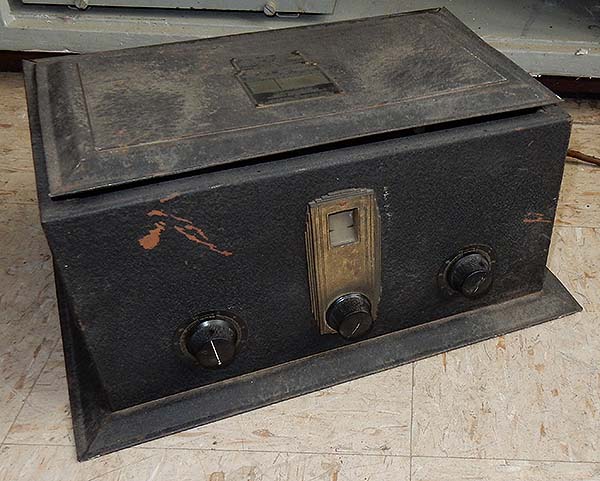
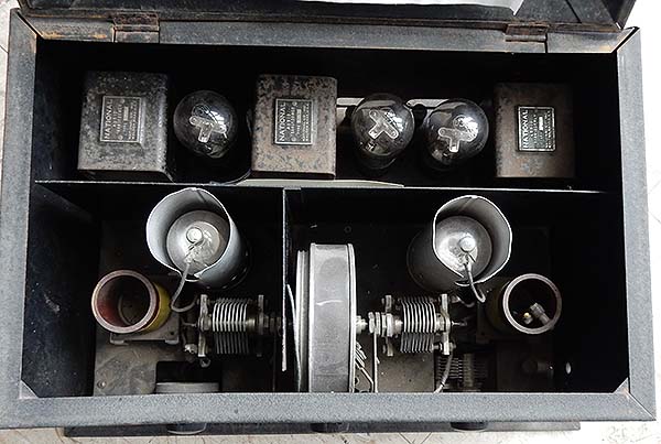
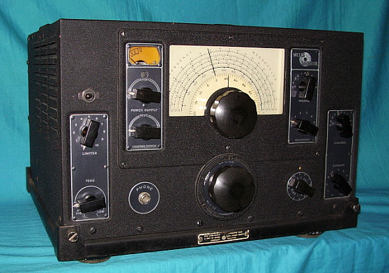
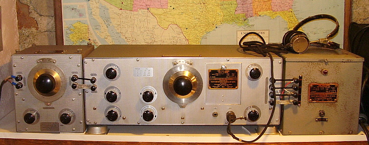
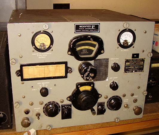
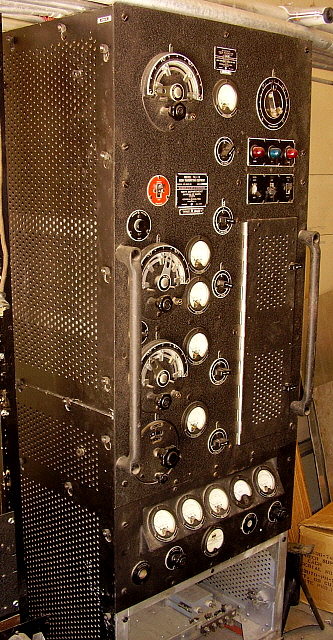
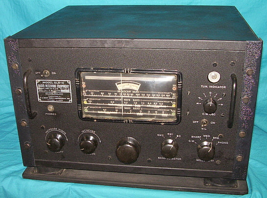
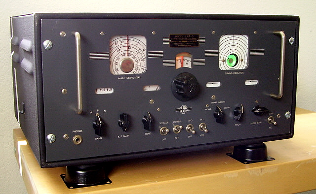 TecRad
LRR-5 from 1945
TecRad
LRR-5 from 1945