Radio Boulevard WWII Communication Equipment - Part 3 WWII Ally Radio Communications
Equipment
Radio Transmission Equipment Co., Ltd. ~ Reception Set R.107 ~ Royal Army Receiver Kingsley Radio Co. ~ AR7 ~ Royal Australian Air Force "HRO Knock-off" Receiver Marconi's Wireless Telegraph Co. ~ C.R. 300/1 ~ Royal Navy Receiver Canadian Marconi Co. ~ CSR-5 ~ Royal Canadian Navy Receiver
|
![]() |
WWII Ally Radio Communications Equipment
|
Marconi's Wireless
Telegraph Company, Ltd. R1155 RAF Aircraft Receiver
Circuit - The R1155 receiver incorporates ten tubes in its circuit however two tubes are exclusively for the "Right-Left" DF indicator circuit, one dual triode tube is for the R-L meter drive and one tube is a tuning-eye tube leaving six tubes to function as the receiver. All tubes are standard British WWII military types (VR99, VR100, VR101 and VR102 types) with optional civilian equivalents listed (and most can be substituted with USA tube equivalents since the tube sockets are standard US octal type though performance may vary somewhat when compared to using the specified tubes.) |
Single preselection is used with a converter tube circuit and
two 560kc IF amplifiers. Audio output is transformer coupled and
is intended for a Hi-Z headset (5K output impedance.) All
voltages to operate the R1155 are supplied through the T1154
transmitter. An interconnecting cable runs from the transmitter
to the right-most Jones plug, P1, on the lower front panel of the
receiver. The left-most of the Jones plugs is P3 which is for the loop
antenna connection (there's a vari-C trimmer and optional fixed
C inside this plug) and the center plug is P2 for the Visual
Indicator connection (R-L meter.) All
inputs and outputs to and from the R1155 are routed through
these three Jones connectors. Voltages required are +6vdc tube
heaters (parallel connection) and to compensate for 12vdc
systems an external Type 47 Resistance Unit was installed or for 24vdc
systems a Type 52 or 52A Resistance Unit was installed. The
+230vdc B+ and a negative bias of around -30vdc were provided
through the T1154 by one dynamotor-type system power unit
(called a "rotary transformer" in the manual.) The "VOLUME"
control operates as a sensitivity control when the AVC is off (furthest
CCW position on Master Switch MS) and as an AF Gain control when AVC is
selected. The BFO is turned on when HET is switched on. The small panel
hole above the dial next to the METER AMPLITUDE control allows
adjusting the HET oscillator frequency. The small panel hole to
the right of the MS allows adjusting the loop
antenna trimmer. All of the controls along the upper
section of the front panel are for the direction finding
operation. Receiver only controls are Band Change, MS, HET
on/off, Volume and Tuning. The R1155 worked in conjunction with
several auxiliary pieces of equipment that included the Visual
Indicator Type 1, the Loop Antenna compass, the Antenna Switching
panel Type J, Type 192 Mic/Tel panel. Sometimes the setup included two
Visual Indicators at each station (radioman and navigator.) Up
to three antennas could be connected to the R1155, the loop
antenna, the sense antenna and the trailing wire antenna,
depending on the service the receiver was going to perform
(communication or navigation) and on what frequency the receiver
was operating.
The "A" in R1155A indicates that MW filters are installed to eliminate broadcasting interference at the IF (560kc.) "B" indicated the receiver had additional filters for operating near radar systems. There were several designated internal options available running up to a "N" version. Most variations indicate SW (radar filters) and/or MW (AM-BC filters) internal filtering, construction material (aluminum or steel) and in some cases end use. Some versions were for mobile-land use, some were used in ground schools and there were two types for marine use (air-sea search-rescue aircraft.) There were several types of 230vac 50cps power supplies available for land use. Some R1155 receivers were built on steel chassis with steel front panels and steel shielding. These were undoubtedly for ground use or installations other than airborne - the steel receivers are noticeably much heavier than the aluminum receivers. Most receiver cabinets have five cork panels glued to the inside recessed areas. The rear inside cork panel has the vacuum tube locations and tube types shown on a glued-on paper label. |
photo above: A very original example of a R1155B receiver
with lots of "use patina."
It appears to be virtually complete and all original although
judging by the "mod plate" (modifications record - the metal tag
to the right of the band switch) this receiver has had several
"upgrades" installed over the years. "B" versions had
internal filters for operation near radar in addition to the MW
filters. Note the
six-digit serial number indicating that production quantities of
R1155 receivers was quite high. Also, note the dates on the
various tags in this receiver,...1967,...this R1155 was in use for quite a
long time after WWII. This example is fitted with the improved
two-speed tuning knob. This receiver is also fitted with the
"blocking plug" that has the "COMMUNICATION RECEIVER"
tag on the front indicating this R1155B was used in a "dual
receiver" set-up where the navigator had the DF R1155 and the
radioman had this receiver and the DF abilities couldn't be used. This receiver also has the Jones plugs
retaining strap installed.
|
DF Controls - The R1155 used an external "cross-needle" Visual Indicator meter (actually two meters within the unit) to show visually if the airplane was on-course. First a homing beacon station was tuned in. Then the receiver was switched to "BALANCE" which connected an antenna coil into the circuit and METER BALANCE was adjusted for the two meter needles to be equally in the "crossed" position. The receiver was then switched to VISUAL and the loop antenna placed perpendicular with the fuselage (athwartship) and the airplane steered toward the beacon which showed the crossed-needles on the meter when on-course. The pilot would deviate his course slightly and if the crossed-needles moved off-center-downward the beacon was behind the airplane. The pilot would turn around, the course aligned and then any deviation moved the needles off-center-upwards, indicating the beacon was ahead. As the airplane approached the beacon the signal would get stronger and METER AMPLITUDE was adjusted to keep the crossed-needles near the center of the field. METER DEFLECTION HIGH-LOW changes the sensitivity of the meter depending on the signal strength of the beacon. Alternately, if a specific direction of an unknown signal was desired, such as in a "search and rescue" operation, then the receiver was switched to the horizontal figure-8 position (loop antenna only) which then allows a bi-directional response to the signal as referenced to the loop's position relative to the airplane's fuselage and its direction of flight travel, to be determined. With the signal tuned, the loop antenna is rotated watching the TUNING INDICATOR (eye tube) looking for a minimum signal which would be one of the bi-directional nulls. The loop is then rotated +90º and the AURAL SENSE pushed to the right, if the signal is reduced in strength then the signal's location is toward the front of the aircraft fuselage (if the loop and compass are set for 0º being the nose of the aircraft.) If the signal increases instead, then the loop is rotated +180 degrees, the AURAL SENSE pushed to the right again and the signal should decrease indicating the correct signal location is in front of the aircraft fuselage. Alternately, true direction can also be determined by alternately pushing AURAL SENSE both L and R, which ever produces the lowest level signal is the correct direction of the signal origin in relation to the aircraft fuselage and the aircraft's course bearing. The SWITCH SPEED changes the multi-vibrator switching rate at the modulator circuit with the combination of the phase-shifted loop with the sense antenna. The meter drive output and mixer circuit uses the multi-vibrator speed in combination with the receiver detector output indicate a phase change between the loop and sense antennas (caused by the airplane's course versus the path of the beacon's signal) that then drive the meters indicating right or left of the aircraft position. The speed settings are LOW 30hz for a voice beacon (like using an AM-BC station as a beacon) or up (high 80hz) for a CW or tone beacon. For more detailed DFing and navigation information go to the "USN & USAAF Airborne Navigation Equipment" Part 2 of WWII Radio Communications Equipment. |
RAF Modifications
- It's common to find complete and original R1155
receivers that are missing V1,V2 and V9. When the radioman's
receiver was paired in the airplane with a navigator's R1155, then these three
tubes were removed from the radioman's receiver. These were the three
main DF tubes and if the receiver was just to be
used as a "receiver," V1,V2 and V9 were pulled to drop the tube heater
current requirements (900ma drop, almost an amp.) The tube
heaters are wired in parallel so pulling tubes that weren't
needed wasn't a problem. Also, a dummy plug (called a "blocking
plug") was inserted for the
loop antenna cable and the Visual Indicator cable when the R1155
was just to be operated by the radioman.
Nowadays, if the missing tubes are going to be replaced, V1 and V2 are CV1099 tubes that are inexpensive and easy to find. V9 is a dual triode, VR102/BL63, of which the USA equivalent is the 6F8G. Audiophiles have driven the price of both the 6F8G and the VR102/BL63 into the stratosphere. Why? Because the 6F8G is the pre-WWII predecessor to the ubiquitous 6SN7 dual triode for which audiophiles will pay exorbitant sums of money (for certain variations of manufacture.) In the USA, it's probably easier (less expensive anyway) to find a 6F8G at about $20 to $50 (for used/tested good) rather than to try and compete with the audiophiles for a VR102/BL63 at over $100 a piece. |
Amateur Modifications - Like the BC-348 here in the USA, there are a lot of surviving R1155 receivers in the UK today. But, also like the '348 in the US, a complete and all original R1155 is a rarity and difficult to find. The R1155 was available on the British surplus market for very low prices starting in the mid-to-late-1950s. And, like the hams in the USA with the BC-348, the British hams bought the R1155 as an inexpensive way to obtain a decent receiver and then "modified" the R1155 to suit their needs. Most often the direction finding circuits were entirely extracted from the receiver since they weren't going to be needed but the space they had occupied on the chassis was going to be needed for their ham mods. With the right side of the chassis nearly vacant, an AC power supply was generally built into the receiver. There were other mods that were published in the British ham magazines of the time that advocated even further destruction of the receiver's originality. The result is that today, like the BC-348 in the USA, very few "complete and original" R1155 receivers exist. |
A Ham "Extremely Modified" Example SN:68154 Here's a R1155 receiver that has had just about everything involving the DF circuits removed from it and even more done to the remaining circuits. Even the serial number identification plate doesn't match the receiver. What makes it unusual is that this receiver is the "steel construction" version so it wasn't used on aircraft but was a ground receiver. |
|
To the left is a R1155, tagged as SN:68154 and
ID'd as an "A" version. The receiver's ID/SN plate indicates
the receiver is a R1155A but it's built on a steel chassis with
a steel front panel and steel shielding. This receiver is
actually a R1155D which was the early steel construction
version. Even though the DF section was "stripped out" it
appears that there never was a MW filter installed indicating
the receiver is the "D" version.
The Mod Rundown,... 1. Removal of all DF circuitry, wiring and components - All DF controls removed. Much of the hardware was also removed and discarded. Most original knobs gone. 2. Antenna input - This is a brown bakelite binding post terminal-type that was "hacked" into the upper right side of the panel. 3. MS (Master Switch) Relocation - Of note is the vacant MS area. The switch was moved to allow the installation of the power transformer which is located directly behind the panel where the switch had been. The MS was moved to the METER BALANCE (pot control removed) location (upper left side of the panel) and only two positions were wired - AVC and Manual Gain with BFO on. 4. Power Input Changes and Electrodynamic Speaker Intentions - The Jones connectors were entirely removed and an aluminum plate installed. The four pin tube socket had been intended for an electrodynamic speaker with the field coil doubling as the power supply filter choke. The AC power ON switch is the only original type R1155 toggle switch. SN:68154 was modified in Canada so the power transformer used for the AC power supply was a 115vac primary type built by Hammond. AC power cord exits out the front of the panel. 5. Lo-Z Audio Output with a Boost - With the VR102 dual triode R-L meter driver removed, a 6F6 audio output stage had been added at that location. A Lo-Z audio output transformer was added after the original Hi-Z audio transformer had been removed. 6. Logging Scale - The Fine Tuning logging scale was removed sometime in the past. 7. Cabinet Destruction - Two one inch diameter holes were punched in the top of the cabinet. Nine one inch diameter holes were punched in the right side of the cabinet. A common hamster thought fallacy that the onboard an AC power supply and a high power audio section would get so hot that complete cabinet ventilation was going to be necessary. |
Mod Makeover
- I had to perform a few minor repairs to get the receiver
operational but these were just small problems that had developed over
the years of moving and storing and then shipping the receiver (from
Arizona to Nevada.) The
majority of the serious rework was correcting the mod-design flaws and
basically making the mod changes a bit more professional-looking.
I replaced the amateur-looking raw aluminum subpanel in the lower right section of the main panel with a new black wrinkle subpanel. I also removed the old brown bakelite dual post antenna terminal and filled the non-original holes with epoxy and painted over to hide the fill. I added military-style Antenna-Gnd push terminals on the new sub-panel (although for a Brit receiver they should have had "A-E" and "E" engraving.) I added the red jewel pilot lamp because the R1155 has no visual indication that the power is on (the dial is not illuminated.) I replaced the 1920s-era phone jack with a single circuit phone jack with a toilet seat cover that's marked "Speaker 2nd Audio" - both jack and seat were out of the BC-342 junk box. I eliminated the four pin tube socket and discarded the idea of using an electrodynamic speaker. I rebuilt the AC power supply to use a filter choke instead and to have the audio drive a PM speaker. The mod had used a 5Y4G rectifier tube and it was found to be defective. I rewired the socket to use a 5Y3GT which is much easier to find and physically smaller. The defective can-type multi-section electrolytic (not original) was removed to have room to install the filter choke. I then used two new axial-type electrolytics mounted under the chassis. I left the AC power cable exiting out the front because any other exit route would further destroy the already seriously damaged cabinet. >>> |
>>> I had to leave the MS in the Meter Balance
location since the power transformer prevented moving it back to
its original location. I did move the HET wires from the MS and
repurposed a vintage toggle switch to now
separately operate the HET (BFO) from the correct location.
The "re-do" did require some rerouting of the "mod routed" wires. Many of the wires had rubber insulation which has a tendency of drying out and then falling off whenever the wire is flexed. I had to replace several wires that were in this condition. The dial cover was removed and thoroughly cleaned which improved the transparency of the original convex plastic. The dial scale was also cleaned which greatly improved the dial appearance. A new gasket was made for the mounting interface. Most of the vacant holes were fitted with control knobs even though all are "dummy knobs," that is, just for appearance. Since the receiver was far from original I painted-over the yellow hand-painted lettering. Mechanically, the two-speed dial knob assembly needed a complete overhaul in order for it to function as intended. The smaller front knob is 1:1 "fast tuning" and the larger back knob is 1000:1 "extremely fine tuning." The conical drive wheels had been greased and the cork friction gasket was also greased. Needless to say, the drive wheels didn't move the reduction plate until all of the grease was removed and all surfaces thoroughly cleaned. This two-speed tuning knob was a constant source of problems when the receiver was in use during WWII probably because the reduction drive relied on friction only. By mid-WWII an improved replacement tuning knob was available. However, not many R1155s had the improved two-speed knob installed so this example does have the commonly encountered, older, problem-prone, original two-speed knob installed. |
General Performance
- Overall, the R1155 performance results will depend on the
operator's expectations and experience with vintage gear, the operator's QTH and the antenna
used. The R1155 is a capable receiver as far as sensitivity is
concerned and a resonant or tuned antenna will allow excellent
reception of most HF signals. Audio is for phones but SN:68154 had a 6F6 audio
output stage added so it easily drives an 8Z loudspeaker. BFO
provides enough carrier for either CW or SSB copy and the
"extremely fine tuning" function allows easy tuning of those CW
or SSB signals. The tuning eye tube only functions on AM
signals. The IF bandwidth is
fairly broad and not really adjustable. For its use on an
aircraft during WWII, sometimes with the plane being shot at,
narrow bandwidth would have been a disadvantage. If the radio op
needed to change frequency under those conditions and was
searching for a homing beacon signal, a broad IF would make finding
such a signal easier. Also, at altitude the interior of the
airplane was cold and the radio op wore flight gear that
included insulated gloves which made any "fine tuning" nearly
impossible (sometimes it was a "gloves off" operation performed
as quickly as possible.) The lack of a crystal filter or other means to
narrow the IF bandwidth isn't surprising. For what is essentially a "one RF
amp, converter and two IF amps" receiver, the R1155 does a
surprisingly good job. Though, if up against the BC-348 with its "2 RF
amps, Mixer, LO, three IF amps and a Crystal Filter," the R1155
would probably come in second as a radio receiver in such a
comparison.
The R1155's desirability nowadays probably isn't its performance as just a receiver. The original R1155, with its ability to DF with its associated rotatable loop antenna and sense antenna, its ability to drive an external R-L indicator meter and also perform adequately as a radio receiver make the "complete and original survivors" the most interesting and desirable versions. However, the majority of R1155s didn't make it past the hackers that, in their enthusiasm to perform yet another "surplus to ham radio conversion," have relegated most of these historic receivers to a "relic" status. |
|
Modified Example with Steel Construction |
|
|
A Minimally Modified Example - Mods to SN:34471 SN:34471 appeared to be very good looking example that was complete and original, that is, until it was examined closely. Here's a list of the types of mods that might be found in almost any R1155 receiver that seems to be "all original" and that assessment is based on using photographs or a cursory visual examination for the inspection process. Not that I'm complaining! This receiver was very easy to return to original. |
1. V1 & V2
Grid Leads Mod - V1, V2 and V9 were missing which
wasn't too surprising. A close look when installing a couple of
CV1099 tubes for V1 and V2 revealed
that the grid cap wires for these tubes were gone. Wire was
"cut" from junction of C56 and R57. New grid
leads made with rubber insulated wire to correct. 2. The grid lead for V9 was still present but had been wrapped with friction tape to insulate. Removed tape and installed grid lead on the 6F8G that was installed for the V9 function. 3. Trailing Ant Mod - R62 (static drain R) was disconnected from pin 2 of the P1 Jones-type receptacle. This resistor was in place to drain static build-up from the trailing wire antenna. Resoldered R62 for originality. 4. HET OSC Mod - It was noted that a couple of non-original looking wires (bright orange and blue plastic insulation) exited the BFO box on top of the chassis. Tracing the two wires revealed that it was a mod that parallel-connected an air variable with the HET ADJ condenser with a non-original air variable C mounted in the METER BALANCE position. This mod was to provide a front panel BFO control. This mod resulted in a missing R51 (a 20K linear taper pot) that was for the METER BALANCE circuit. Luckily, the three wires that were connected to R51were still present. Desoldered orange and blue wires and removed. Removed non-original air variable C. Installed vintage 25K pot and connected original wires. 5. A non-vintage 18.2K WW resistor added to the switched B+ in series from HET switch to the BFO tube circuit. This may have been to reduce the BFO level (for weak CW stations) or it may have been to compensate for the addition of Mod #4. Removed WW resistor and reconnected original wire to HET switch. >>> |
>>> 6. V9 Mods
- There appeared to be some modifications that were never
completed involving V9. A small audio output transformer was
mounted under the side rail. Only one end of the primary winding
was connected to pin 3 of V9. There were no other connections to
this transformer with the opposite end primary wire not being
connected to anything. The secondary was shorted together with a
jumper. Perhaps it was going to be used as a choke. The original
wire from pin 3 to L26 had been cut and removed. R65, a 10K
resistor, was disconnected from pin 5, one of the grid inputs on
V9. The jumper wire between V9 cathodes, pin 4 to pin 8, had
been cut. Installed new wire with rubber
insulation to replace missing pin 3 to L26 wire. Reconnected R65
and resoldered cathode jumper wire. 7. Multivibrator Speed Switch - wasn't an original component. Made in USA toggle switch. Removed non-original switch and replaced with an original R1155 toggle switch. 8. Nomenclature Plates
- I wondered about the gold color on the Band Change, MS,
Logging Scale plates and the SN plate. I closely examined each
plate
and they are vintage nomenclature "covers." These
nomenclature plates were later additions that were generally
installed during a depot rebuild to deal with worn original
silk-screened nomenclature. These plates were originally painted black
with white nomenclature. I believe the paint was worn off because
these are the most used controls and the radioman was probably
wearing heavy insulated gloves that tended to "scrub off" the paint and
"polish" the base metal. I think the serial number plate is
another matter. It appears vintage and was probably "over
cleaned" during an earlier restoration. Restoration of
these plates isn't particularly difficult,...I just haven't done
it yet. The process will require stripping since it appears that
the "fill paint" is still present. Once the plates are
completely stripped and cleaned, then they are painted with
matte black paint that has to be left to fully dry and harden, a
few days minimum. Then the while "fill paint" can be applied.
I've described this process many times in several restoration
articles,...so, after the "fill paint" has dried, then the
nomenclature plates can be remounted. Luckily, these mods to SN:34471 didn't remove very much of the original circuitry or too many original components. Return to the original circuit and configuration was easy to accomplish. More details further down this write-up in "Getting SN:34471 An Original Example R1155 Operational." |
Original Example with Aluminum Construction |
|
|
Getting SN:34471, An Original Example R1155A, Operational The basic return to original was covered in the section "A Minimally Modified Example" above. Here's some more work necessary to actually have an original example also become functional. |
Jones Plugs
- The original plugs were basically Jones style connectors.
Where they differed was how the cables were routed as they
exited the plug shell cover. Original British plugs had the cables exit out
the bottom of the plug cover. A cable clamp fitting was
installed on the bottom of the plug cover that further routed
the cable back under the receiver. Modern Jones plugs work and
fit perfectly but the modern plug covers have the cable exit
directly behind the plug at the center-back of the cover. To
make my modern Jones plugs look more like the originals I had to
do a few modifications. First, for the Loop Antenna plug, P3, I
used an eight pin male plug and removed the locating pin which
was slightly off from the original location and then also
removed four of the blade pins so P3 would be a four pin male
with a long body. The long body is necessary because inside the
back cover is a variable trimmer capacitor and a fixed-value
capacitor that connects to the pins of the plug. These
components were used to trim the airplane loop antenna, cabling and routing to
match the receiver loop input impedance. For all three modern plugs the cable clamps were removed
and then the rolled metal trim around the hole was
removed with a file. The back hole was then covered with a "butch
plate" made from .030" aluminum. The aluminum cover piece was
mounted to the rear cover using four 2-56 screws and nuts for
each cover piece. A new .437" hole was drilled into the bottom
side of each cover. Next, the "butch plate" covers were mounted, cleaned and
then painted black wrinkle finish. Rubber grommets were
installed into the bottom cable exit holes. I didn't install the
modern cable clamps since they were nothing like the originals
and wouldn't allow routing the cables directly back under the
receiver.
Wiring P1, P2 and P3 Jones Plugs - P1 is the right-most Jones connector. This is the input access for providing tube heater voltage or 6.3vac (originally 6.0vdc in the aircraft which depended on the drop provided by the external resistance unit used.) Also, about +230vdc for B+ and about -30vdc for the bias needs. Additionally, antenna inputs for both the trailing wire antenna (for MW reception) and the fixed antenna (for SW reception.) A chassis connection is also required. The audio output also is from P1. The audio is 5000Z and runs at 'phones level. All receiver voltage inputs and the audio outputs are accessed at P1. P3 is just for the loop antenna input. The plug, as mentioned, has a trimmer capacitor and a fixed-value capacitor inside to match the entire loop and cable impedance to the receiver loop antenna input. P2 is just for the Visual Indicator connections (the "crossed-needles" R-L meter.) >>> |
>>> I couldn't find any vintage photos that showed how the
original cables looked. In all installations it appears that the cables
were routed under the receiver then behind the receiver up and
under the T1154 transmitter and then up to the T1154's lower
front panel connectors that are also Jones-type receptacles. The Visual Indicator and the Loop Antenna also appear to
connect from behind each of the devices. The antenna cables from
P1 usually connected to the antenna switching panel Type J.
Nearly all cabling is not really very visible in the original
photographed installations. A Test Cable for P1 - I made the six wire cable about five feet long. Since this operation was still in the "test mode" I didn't bother to install a shield or to wrap the cable. Also, since this was for test, I tied the two antenna inputs together. I connected the P1 Jones plug to one end and tinned the stripped and bare wire ends on the other end of the cable. The tinned ends were for easy "test" connections to the Lambda Model 25 bench supply that provides 6.3vac at 3 amps for the tube heaters and adjustable B+ that I set for +220vdc. I also connected a small bench supply to provide -25vdc for the bias voltage. I used a set of Western Electric 518W Hi-Z 'phones for audio reproduction. I connected the antenna lead to an indoor ten foot "test antenna." Upon applying power I was surprised to hear a good signal background noise through the 'phones with the receiver tuned to approximately 350kc. I switched over to the AM-BC band and tuned in several stations. No hum and no distortion. The VOLUME control is very noisy in operation, the HET OSC is way off (from the mod that paralleled an air variable for front panel BFO) and the "eye tube" is black (well with some imagination, maybe just perceptibly "dark" green.) All in all, a good "first test." The "eye tube" is a VR103 (CV1103,) something like a 6G5 but with an octal base. The eye tube in SN:68154 was somewhat dim but still easily visible in average room illumination. I swapped the relatively good VR103 with the dark tube from SN:34471. The HET OSC was just a blade screw driver adjustment. With the receiver in MVC/HET operation the VOLUME control is a RF gain adjustment and the noisy operation ceased. I added another wire to the cable so I could separate the antennas. The trailing wire antenna went to the "test antenna" since it was for MW coverage. I connected the outdoor wire, a 135' "T" antenna to the fixed antenna input for SW and was able to tune in hams on 40M and on 20M along with SW-BC stations in the 25M band. |
Building a
Dedicated Power Supply for the R-1155 - Three
voltages are required to operate the R-1155. The tube heaters
can be operated on 6.3vac with about 3 amps of available
current. The B+ can be anywhere from +190vdc up to about +230vdc
with about 65mA of current available. A bias voltage of -25vdc
to about -30vdc is required also.
If building a PS then the +HV winding CT can be floated to
create the negative bias voltage. If a power supply is going to
be constructed, why not add an audio output stage too? A filament transformer can be used for the tube heaters or a power transformer with a filament winding rated at 6.3vac 3A would also work. If a solid-state full wave rectifier is used then the 5vac winding for the 5Y3 isn't needed. The resulting B+ will be at a higher level but that can be compensated for by using a choke input filter (as shown) and a series load resistor, if needed. As stated in the proceeding paragraph, by elevating the CT of a full wave rectified B+ power supply, a negative voltage can be created for the bias voltage requirement. That can be accomplished by connecting the CT through a resistor to chassis (5K 25W shown.) An adjustable "slider" WW resistor could be used and then the bias voltage could be adjusted for best performance (the bias level needed is dependent on the level of B+ used.) The B+ power supply filtering must have the negative connections to the CT which is also B- for the input filter capacitor. If choke input is used (as shown,) then the filter capacitor negatives should be connected to B-/CT. The filtering used will determine the negative connection of the second filter capacitor. With pi-filters and capacitor input, the second cap negative should connect to chassis, if the cap input filter is dual-section, then the second capacitor negative should connect to B- and the third capacitor negative should connect to chassis. Capacitor input filtering isn't shown and if used will result in a very high B+ voltage that will fluctuate with minor load changes. The choke input filtering is lower B+ voltage that is much more stable with slight load changes. Note that the third filter capacitor is on the negative CT with the + connected to chassis ground (polarity isn't shown on the schematic.) A typical power supply with choke input dual section filtering plus 6V6 audio output stage schematic is shown to the right. Since the cathode of the 6V6 is connected to the B- the resulting potential plate-to-chassis is the bias voltage plus the plate voltage, around +250vdc. This results in more available power from the 6V6, although it's probably not really necessary. It's acceptable to also connect the 6V6 cathode to chassis through the 250 ohm cathode resistor and 25uf bypass capacitor. The 6V6 plate voltage will then be around +220vdc. The audio at P1 - pin 5 is a 5000Z secondary winding to chassis from the R1155 audio output transformer, L30. The L30 secondary can drive a set of Hi-Z phones directly. It can also drive a typical audio output transformer (5K ohms to 8 ohms) to drive a loudspeaker directly, just not at a thunderous volume. The 6V6 audio stage shown will provide more volume and operate a standard 8Z loudspeaker. |
|
Using a Test Bench Tube-Type Regulated Power Supply - A typical vintage tube-type regulated test bench power supply will have 6.3vac available, usually with a current capabilities from 3A up to 10A depending on the model of the supply (I'm using a Lambda Model 25.) The high voltage supply is usually regulated and adjustable from around +180vdc up to about +275vdc with a current capability ranging from 100ma. Some super high-quality bench supplies, like the HP-713B, will also have an adjustable bias supply that can provide negative voltage from 0 up to -150vdc at 100mA along with adjustable 0 to +500vdc at 500mA and fixed 6.3vac at 10A. The disadvantage of the HP-713B is its size and weight. It's an excellent power supply fully capable of running many types of receivers or other tube-type equipment, including the R1155 (it's just loafing along when running a receiver.) The problem is that the HP-713B is the size and weight of a Heathkit DX-100 transmitter - in fact, I think it uses the same cabinet! |
Operating Set Up
- I'm using the Lambda Type 25 bench power supply that provides
6.3vac at 3A and adjustable and regulated high voltage from
+180vdc up to +275vdc at 100mA. The Lambda is in a small package
so size and weight are not a problem. I also use an adjustable and
regulated very small RCA bench supply for the bias voltage (so
small it just sets on top of the Lambda 25.) I adjust the
Lambda 25 for +220vdc and adjust the bias supply for -25vdc before
connecting up the R1155. The bias supply negative is connected
to pin 8 on the R1155 plug and the bias supply positive is
connected to chassis. The B- on the Lambda 25 and one side of
the 6.3vac are
also connected to chassis. The +220vdc is connected to pin 5 on
the R1155 plug and the high side of the 6.3vac is connected to
pin 3 on the R1155 plug. I initially connected a Signal Corps LS-3 (8000Z)
to pin 6 of the R1155 plug with the ground side going to
chassis. The antenna was connected to pin 1 (trailing wire.) With the power
supplies pre-adjusted and connected to a power strip, I just
switch on the power strip to power up the R1155.
Audio Reproducers - The audio output driving a loudspeaker isn't thunderous (as would be expected) but it's sufficiently loud for a ham shack room at reasonable volume levels (the audio output was intended for 'phones and it's very loud using a set of Hi-Z 'phones.) For further testing I connected a Hallicrafters PM-23 since it has a 5000Z matching transformer. This provided a better match and the audio reproduction was very good. Still not thunderous but relatively loud. However, the PM-23 is an enormous loudspeaker that's fairly heavy. As another "see what happens" test, I connected a small 600Z loudspeaker. This provided more volume but the quality wasn't good at all. More volume but easily more distortion. Without additional audio amplification, the best reproducers I've found are by far a set of Hi-Z 'phones. I'm using a vintage pair of "Trimm Radio Company" of Chicago "Professional" 'phones, so nothing fancy. They have ample bass response (surprising) and "roaring volume." It's amazing how much audio there is when using a good set of Hi-Z 'phones,...but then, that's what the R1155 was designed to operate with and the Trimm Professional 'phones, or any Hi-Z 'phones, make that obvious. Also, the Trimm Professional 'phones don't have the large leather covered padded ear cushions either but the cups are physically much larger than the typical WWII 'phones (and the cup-covers have one large opening rather than a multitude of tiny holes) so I just use the uncovered bakelite 'phone cups. That way it's easy to have the 'phones slightly in front of the ears to prevent sudden loud "crashes" from causing "ringing ears." Vintage Mil-Rad Station - I don't have a British airborne transmitter like the T1154 to go with the R1155. The closest WWII airborne transmitter I have to the T1154 is the USN/Bendix ATD. This is a 40W Voice and CW transmitter that runs on its matching dynamotor. I connected the R1155 antenna input to the "Receiver" terminal on the ATD for isolation but still the volume has to be reduced when transmitting. When using 'phones and transmitting Voice, the signal can be heard and can be used as a monitor of sorts. The combo works very well on 75M. Power to the R1155 is provided by the Lambda Model 25 and the RCA bias supply located on a desk behind the set-up with the cable from the R1155 routed back to the supplies. The ATD uses a homebrew +28vdc 80amp power supply to operate its original dynamotor (both are located on the floor under the desk in the foot well.) Note the series high-voltage doorknob capacitors that add just enough C to allow the ATD to load up a 50Z low reactance antenna. Mike is a Shure 102C carbon microphone and the key is a USN flameproof type. Phones on top of the R1155 are the Trimm Radio Co. Professional Hi-Z type. |
|
Reception Set R.107 Mk.1/1 - Z.A. 25266 - TPH SN: 1221 |
|
History
- The Reception Set R.107 was designed in 1940 specifically as a high
performance, general purpose receiver for the Royal Army.
Two Types of R.107 - This Reception Set R.107 Mk.1/1 has the military identification number Z.A. 25266 which identifies it as the later version of the R.107 with earlier R.107 receivers identified as Z.A. 3220. The most apparent easily visible difference between early and late versions is the tuning dial. Early dials (most of them anyway) were painted cream-color and the scales were different colors. Later version dials were semi-polished aluminum with engraved scales that were paint-filled with different colors. Cloth insulated wiring is used on early versions while later versions used rubber-plastic insulation wiring. There are several other differences but the dial and wiring are the most obvious. Tubes Used - The R.107 was a nine tube set (8 tubes plus rectifier tube) but only three types of tubes were used in the set. Four CV1053 tubes, four CV1055 tubes and one 6X5 rectifier tube. The British tube numbering had several different designations for the same tube type. The CV1053 = EF39 = ARP34, is a pentode tube with standard octal base. The CV1055 = EBC33 = AR21, is a duplex diode/triode tube with a standard octal base. The pentodes are used as the RF Amplifier, the Mixer and the two IF amplifiers. The duplex diode/triodes are used for the HFO, the BFO, the Detector/AVC (the only place where the diodes are actually used) and the Audio Output tube. Only the triodes are used in the HFO, BFO and Audio Output functions and the diodes are not connected. All of the receiving tubes have a metalized, conductive-paint coating that provides the RF shielding by way of a thin copper wire wrapped around the top of the bakelite base. This wire is covered in the metalized-paint coating and the other end of the wire is connected internally within the tube base to pin 1. The DC resistance of the conductive paint coating to base pin 1 is very low. When the receivers were built, all of the tube sockets had pin 1 wired to chassis, thereby grounding the painted shielding when the tube was installed. The 6X5, being the power supply rectifier, has no conductive coating. This "later version" R.107 has the "CV" designators installed for tube location indicators. |
Power Sources Needed
- The R.107 could be operated on +12vdc
directly because it had a built-in vibrator power input. The
external storage battery input goes directly to the dual point vibrator
through the power transformer's special center-tapped and shielded
primary winding that allows the operation of the dual point vibrator to
create a "switching voltage" that is essentially AC at the power
transformer "vibrator primary winding" and creates the necessary AC
voltages at the secondary windings of the power transformer. Unlike many
types of DC vibrator power supplies, the R.107 actually runs the tube
filaments on AC when the receiver is operated on DC voltage. The
tube filaments were connected in series-parallel to conserve current
requirement when operating on DC (or AC also.) The receiver could
also be operated directly on a wide range of AC voltages (from 100vac up to
250vac) utilizing the special tapped primary power transformer. An internal
switch allowed selecting either AC or DC as the power source for the
receiver. Interestingly, since the DC input voltage goes directly to the
vibrator and power transformer vibrator primary (and no place else)
the polarity of the connection isn't important since the output of the
vibrator only operates with its dedicated power
transformer primary, however one should be aware that the upper two
terminals are connected to the receiver chassis and that might be
important to other inter-connected devices when the R.107 is in actual
DC operation. Antenna Requirements - The Reception Set R.107 tuned from 1.2mc up to 17.5mc in three bands. The tuning featured a two-speed combination direct-drive and a reduction vernier drive for "slow-motion" tuning. The R.107 circuit used a single preselection front end, two 465kc IF amplifiers with two selectable IF bandwidths and tertiary-coupling (using two series-connected IF transformers) for the second IF amplifier input transformer providing steep slopes for good selectivity. Wide bandwidth was about 7kc and Narrow bandwidth was about 3kc. Sensitivity was rated at <1uv for CW and 2uv to 6uv for Voice. The Aerial inputs are "Open Aerial" which bypasses the primary winding on the Antenna coils and is connected to the first RF amplifier grid LCs (this connection is to a tuned parallel LC on the grid - not RF transformers.) This would be for non-tuned relatively short length antennas. The "Dipole Feeder" input is two terminals that are routed to the primary windings on the tuned Antenna LCs using actual RF transformers ahead of the RF amplifier grid input. This was intended for balanced feed lines such as used on dipole antennas with an expected impedance of around 70Z to 100Z (twisted line was popular around 1940 for dipole feedline with an expected impedance of 100Z.) Unbalanced line (50Z or 75Z coax) can be used by connecting one of the Dipole Feeder terminals to the Earth terminal (chassis ground) and using the other terminal for the center conductor. One has to test which terminal to ground works best. The manual states that the right terminal is "earthy" but performance is what actually determines which connection works best. With my R.107, the left terminal connected to Earth works noticeably better with the matched Collinear Array antenna (the manual does say to "try" both connection set ups for best performance.) Other Features - The R.107 had features like a "Crash Limiter" that was a noise limiter to reduce the intense pulse noise from lightning crashes, a narrow CW audio filter (900hz peak) that could be switched in if needed, a 600Z line audio output, dual parallel Lo-Z phone jacks and a built-in 4" diameter Goodman Industries loudspeaker that could be switched off if necessary. The TEL OUTPUT control only adjusts the level of the two Lo-Z jacks. The 600Z line audio output is from a dedicated winding on the audio transformer and the output is dependent on the settings of the RF and AF gain controls and the signal level being received. Additionally, the associated transmitter's sidetone signal could be routed through the R.107, if desired. An unusual feature is the black bakelite circular housing at the upper center-left of the panel. This was for holding a 2" diameter pocket watch as a time indicator (probably for the radio operator's pocket watch - the British military were issued watches that had "GSTP" engraved on the back - "General Service Time Piece.") The yellow "T" indicates this receiver was "Tropicalized" (a lacquer coating on areas that could corrode, screws, components and soldering. Sometimes the lacquer would contain a fungicide and was then usually referred to as "MFP" for "Moisture and Fungus Proofing.") The top of the case also has a "T" indicating the same thing. The small metal tag has "R/TPH 1221" and in several places within the chassis are many red ink inspection stamps indicate "TPH" leading one to conclude that "TPH" was the contractor for this receiver. I can't find any British Radio company that used those initials during WWII. However, it's interesting that Ferguson Radio Company was a Canadian company that supplied R.107 receivers to the Royal Army during WWII. It might be possible that "TPH" was another Canadian company. Another possibility is the the "R" that proceeds "TPH 1221" on the serial number tag indicates a rebuild or refurbishment of this receiver and the red ink inspection stamps relate to the rebuild. At this point, I can't really find any definitive information on what "TPH" indicates. Onboard Troubleshooting, Muting, Sidetone - One interesting feature was the small testing pin-board on the upper part of the front panel. This feature allowed the operator to check (while the receiver was in operation) the cathode current of each of the vacuum tubes via measured IR drops across a 3K test resistor. The manual gives the expected voltages that should be measured when the receiver is operating correctly. Also, the two large pin outlets on the testing pin-board provided access to the tube filament voltage (for a small lamp, probably for visual troubleshooting purposes.) Even more troubleshooting information was in the manual for all of the voltages and resistances that could be measured on the four "tag boards" that were wired together (tag bds. A to B and tag bds. C to D) to interconnect the three modules that comprise the receiver. The other connector is the Sidetone and Muting inputs. The upper large pin is Muting in and one should know that B+ is on this pin when the receiver is on and the pin exposed. By using an external Antenna Relay that has a set of NO contact that switches to NC upon transmit and having those contacts connected to the upper large pin and the middle small pin, the B+ will be routed through dropping resistors to actuate the receiver's internal Muting relay which routes the transmitter sidetone to the CT of the 600Z winding of the audio transformer and grounds the grid input of the audio output tube. The lower large pin is for Sidetone which is usually provided by some types of transmitters as a keyed audio tone that allows monitoring the CW sending. Some transmitters also had the Sidetone provide an output in the Voice mode also. The R.107 Muting and Sidetone functions were intended to operate with specific British Army transmitters like the Wireless Set No.12 or the Wireless Set No.33. Physical Details - The three modules are the RF section, the IF/AF section and the Power Supply section. Each module was removable from the main frame and front panel assembly. This modular approach was to ease repairs in the depot for quick turn-around although module removal is far from easy requiring substantial disassembly and unsoldering. The testing pin-board and the tag board information was provided to hopefully allow easy repairs to be accomplished in the field. The later versions of the R.107 had storage inside for five spare tubes and a spare vibrator. The chassis mounted into a large steel case with double carrying handles (side or top.) There were four threaded bosses in each corner of the front panel that were for mounting the cabinet front cover. When the front cover was removed, it could be mounted to the back of the cabinet using the similar threaded bosses located there. The entire weight of the R.107 was approximately 95 pounds and it measured 24"W x 13"H x 17"D. The removable front cover that could be screwed to the back of the cabinet for storage but if the front cover wasn't mounted front or back, the case would be about 14" in depth. |
Reception Set R.107 Mk.1/1 - Refurbishment |
Preliminary Inspection
- Apr 16, 2025
- The R.107 is complete but I haven't thoroughly inspected it for
functionality yet. The seller said that it worked (but we've all heard
that before,...but in this case, it was true,...well, basically true.) The tubes can be tested on the TV-7B. I had to build a new
(more authentic looking) AC power cable first. AC cable was quickly finished.
I then tested
tubes and found that all of the tubes installed in the receiver tested good. All
of the spare tubes also tested good except
for one spare CV1055 had one bad diode and the triode barely moved the
meter. I tested the filter capacitors in the power supply to be sure
that they
seemed to charge and that there wasn't a short on the B+ line.
I double-checked that the power transformer primary was connected
for 120vac operation which required removing the power transformer
cover. So the R.107 was now ready to power up. I wanted to bring the R.107 up on a "soft start" initially. The seller had powered the receiver and checked it out but all of the tubes have been in and out and, of course, the R.107 had travelled from the East Coast to Nevada. "Soft start" is just increasing the AC input from 0 to 120vac in about ten seconds,...nothing radical. I usually "soft start" the equipment for maybe the first few times until I'm fairly confident that the circuits will survive the regular power up. Of course, being a rectified power supply with a vacuum tube rectifier, the B+ "soft starts" anyway since the rectifier tube doesn't conduct for several seconds and then increases within four or five more seconds to full rectified voltage. I had a 15 foot long wire on the floor for the antenna. At first I just heard the normal operational noises through the loudspeaker. BFO was operational. AF and RF gain controls functioned, just no signals. This was during the day, so the upper end of Band 3 and all of Band 2 didn't have any signals anyway. The lower part of Band 3 had a few AM-BC stations coming in with the local (well, 25 miles away) AM station being fairly strong. I heard a few heterodynes on Band 1 but nothing strong. So, the R.107 was fairly operational. I'm sure it needs alignment and it needs to be connected to a better antenna (how true.) |
|
Problems Found During Initial
Inspection: 1. The long screw that is on the lower part of the front panel and passes under the chassis to thread into a welded bolt on the back of the cabinet is broken. This appears to be an old break, so lucky the long screw didn't come out and get lost. I'll have to repair the long screw by making a new end and then attaching it to the end of the screw. The length has to be correct for the new part so that the screw will pull the bottom of the front panel into the cabinet. I used a .25" opening metal coupler with a "cut to length" 1/4x20 shoulder bolt with the head cut off. I had to "cut to length" the long bolt so that the coupler could rotate when tightening or loosening the screw and not interfere with anything under the chassis. The long screw has to go through the cross-strut of the main frame. The long screw with the coupler has to be assembled installed under the chassis because of the holes that it protrudes through. The welded nut on the back of the case was extremely close to 1/4x20 threads but I ran a 1/4x20 tap to make sure the repaired long screw would thread in easily. It would be possible for the coupler set screws to loosen and then the long screw wouldn't be extractable and the rear piece might not allow the chassis to be removed without threading the screw inward from the rear. To prevent this, I drilled two shallow holes in the screw shafts to allow the coupler set screws to protrude into these holes. Now, even if the set screws loosened considerably, the long screw would still be able to rotate and unthread. There are two other short front panel screws that are in good condition. 2. The socket for holding the spare vibrator was missing a screw and nut. This made it difficult to plug the spare vibrator into its socket. The British use "cheese headed" screws which are very similar to Fillister head screws. I installed a Fillister head 6-32, lockwasher and nut to secure the socket. The spare vibrator now mounts securely. If the primary vibrator isn't in use it's mounted upside down (pins up.)
|
3. Most of the vacuum tubes are missing the conductive metalized
paint that acts as the RF shielding. I made sure the IF amplifier tubes
did have complete conductive paint. The HFO tube lost all of its
conductive paint when I removed it for testing. It literally just flaked off
when touched (causing
problem #4.) The HFO tube is in a shielded compartment so, probably no problem. The AF
output tube also is entirely missing its conductive paint but it really
doesn't need it in that function. The Mixer and RF amp tubes are missing
their paint but I don't think that's a problem. The detector/AVC/1st AF
amp tube does have all of its conductive coating. Perhaps after alignment,
with sufficient gain some oscillations might happen but I think the
tubes that are most prone to oscillation do have their conductive paint
in good condition. If I do need to recoat the tubes missing their
conductive paint, that type of paint is easily available on eBay and it
isn't expensive at all. It's usually listed as "Military Conductive
Paint" and sells for about $15 for a 2oz. bottle. I also want to
test "Galvanizing" paint since it's easily available. 4. Tuning condenser was shorting in the upper third of rotation. Problem was due to a large "flake" of the conductive metalized paint from the HFO tube that had fallen onto the stator HFO section of the tuning condenser. When the rotor contacted this conductive paint it caused the HFO to stop working (with significant "scratchiness" coming out of the loudspeaker.) Removing the flake was somewhat difficult because it was extremely brittle and fragile so it would break apart whenever it was gripped with the long needle-nose pliers in order to remove it. After about three tries, I gripped the middle part of the flake and it was able to remove it intact. I brushed the stator with a soft medium-size paint brush to remove any other small flakes. 5. The Antenna Trimmer seems to not adjust the air variable correctly. The problem was the scale mounted to the rear of the knob was very loose (three screws on back of knob.) I removed the knob and saw that the trimmer is a half-shaft and so is the knob. The scale has to be set correctly and then the back screws tightened. Then the knob set screw can be snugged up. |
|
6. Dial lamps are not
working. The dial lamps are wired in series and operate on 12vac. One
lamp actually had a broken bulb but just a small part of the glass was
missing. Usually these glass bulbs shatter. I checked the manual to see if
there was any information on the lamps,...absolutely nothing. Only the
schematic shows that they are connected in series so that implies they
are 6 volt bulbs. The lamp that was good indicated it was 5.5volts at
.5A which seemed a little high on the current draw. I measured the DCR
of that bulb's filament and it was 2.7 ohms. I checked a number of #46 bulbs
(threaded base) and they measured 2.9 ohms and draw 250mA. I installed
two #46 lamps and they operate fine. 7. Left side grab handle was loose and the left side panel was also loose. The side panel has to be dismounted to be able to tighten the bolts that mount the grab handle. The two bolts were tightened, the side panel remounted and its screws tightened. Two nuts on the BFO knob skirt clamp and two nuts on the Tuning knob skirt clamp are missing. These missing nuts are 6BA (British Association standard for small screw/nut sizes and threads.) Clamps still operate even with the nuts missing. The nuts are easily available from many sources, such as eBay (all sellers are in the UK but their prices are cheap and they ship quickly.) 8. Found the Band 2 RF trimmer capacitor had its mounting screws almost all the way unscrewed. I had to remove the RF section shield cover to have access to tighten the screws. Also found that the locking nut on Band 3 Ant L adjustment had backed all the way out and needed to be run down to actually "lock" the L adjustment. Found that the C trimmer for the Ant coil on Band 2 was stuck. I had to use heat from a small soldering iron and DeOxit to break the adjustment loose. I checked all of the front end adjustments to make sure everything was moveable prior to doing an alignment. |
|
9. I thoroughly checked
underneath and it appears the receiver is all original components except
for one carbon resistor. All inspection stamps indicate "TPH" but
I can't find any reference to a British Radio company that used "TPH" as
their identification. The two well-known builders of the
R.107 were Radio Transmission Equipment, Ltd. and Ferguson Radio
Company. At least, those are the two that are always mentioned, more research
needed to discover who or what "TPH" stands for. 10. Dipole Feeder right side terminal was loose and couldn't be tightened. I took this spring loaded terminal apart and the two bakelite halves must fit together and when they are correct there's just enough clearance for the thickness of the front panel metal gauge used (plus paint.) The embossed projections of each half piece seemed to be too high and when fit together the clearance was greater than the front panel metal gauge. I used a small flat file to remove just a slight amount of material from each half. This material removal was sufficient to allow the terminal halves to be snugged up (not over-tightened) and not allow any movement of the terminal when fully mounted. |
The "Slow-Motion" Tuning
Mechanism - The large outer knob of the tuning control is
a 1:1 ratio, that is, there isn't any reduction and that allows for a
rapid placement of the tuning condenser to the general area of tuning
desired. The smaller inner knob is a "slow-motion" vernier
control with a tremendous
reduction that allows for making very fine tuning adjustments. There are six
screws, three accessible at the backside of the reduction mechanism and
three in the front, under the small knob. These six screws are NOT
supposed to be tight or tightened. But, they shouldn't be extremely loose
either. The proper adjustment of these six screws will make the difference between
a very smooth feeling vernier action or one that "grabs and sticks." The
manual doesn't even mention this control so there's no help there.
Probably when the mechanism was new and
freshly adjusted from the factory it worked perfectly. But, that was 80
years ago. Certainly dirt, corrosion, mis-adjustment or wear can ruin
how this vernier mechanism works today. If the vernier tuning does work
but just "grabs" a little bit or maybe gets lightly stuck and turns the 1:1 large knob,
then it probably just needs adjustment. This is especially true if you
can see grease that still has pliability present and it's slightly oozing out
the joints and sides of the mechanism (this means that it's been
serviced sometime in the last decade or so and been kept where the
grease didn't "dry up.")
With the small knob removed, you should be able to rotate the tuning shaft with your fingers. Rotate the shaft until you feel it begin to "grab" and at that point, slightly loosen just one of the front screws trying the shaft to see if the "grabbing" is gone. If that screw doesn't change anything return it to the position it was and go on to the next screw. There are three screws on the backside too. These are accessible without removing anything. So, try them - one at a time - to see if the "grabbing" stops. Sometimes it takes two loosened screws to achieve adjustment. Never move the screws more than one-quarter of a turn. If the screws are too loose then some back-lash will result. It's a compromise between smooth, low-resistance tuning and excessive back-lash. When you get the vernier mechanism rotating smoothly don't mount the small knob as far in as it will go. This will have the back of the knob hub rubbing against the vernier mechanism. Allow just a little spacing for no rubbing and that will result in a very "light touch" to the "Slow-Motion" tuning. Don't clean the grease off of the vernier mechanism. Grease is a British rust prevention compound (almost any metal left outside in the UK will rust or oxidize quickly.)It's possible that if the grease is dried up then the vernier mechanism might have to be removed in order to thoroughly clean and lubricate it. It's fairly easy to remove but it can't be totally disassembled without destroying it. The mechanism can be soaked in a degreasing solution. Then the new grease pushed in through the screw holes. This should clear-up any "sticking" or roughness. There's a write-up online from the UK Radio Museum that describes the procedure. You should be somewhat familiar with the R.107 tuning mechanism when reading this write-up in order to understand what the author is describing (British vernacular is liberally used throughout the write-up.) |
|
Conductive Paint Tube Shields
- A lot of British and European tubes were coated with a conductive
paint on the glass envelope to act as a RF shield. The top of the
bakelite base usually has a small gauge copper wire wound around it with
the wire somewhat in the groove between the bakelite and the glass.
There's usually a very small stub of copper wire that is supposed to be
under the coating to provide an extra connection to ground. The copper
wire is routed through the base and connected to pin 1 on octal based tubes that are
intended to be shielded. When the radio gear was designed and built, pin
1 of the octal tube sockets was wired to chassis-ground. At the time,
this conductive paint had good survivability and usually lasted for
decades. But, now this conductive paint is quite old, maybe not 80 years
old, but still several decades old. The paint has been heated when the
tube was in use and left to get
cold when not used. The paint could also have been exposed to humid
conditions. At any rate, the original conductive paint is nowadays usually
extremely fragile and ready to fall off or has
already fallen off. Conductive paint is easy to find and not usually expensive. The most expensive is nickel-based and the cheapest is carbon-based (there's also copper-based.) For tube shielding the carbon works fine. I bought 2oz. off of eBay for $11 plus shipping for $15 total. I only used about 5% of the 2oz. to paint six tubes, so only a small amount is needed. Before starting, I used a yellow paint pen to write the tube identification on the bakelite base. Clean off any residual old conductive paint using a razor blade and clean the glass envelope with Glass Plus. Scrape clean the copper wire that's wrapped around the top of the bakelite base using a razor blade (it should have several places that are bare metal for good contact.) I had to practice on one tube to get the proper brush stroke technique to get good coverage and a fairly smooth finish. The conductive paint I used dried very quickly (and it didn't smell and it was water-soluble.) I tested the resistance between pin 1 and the paint measuring about 25 ohms, which is very conductive. I proceeded to apply the conductive paint to all of the tubes that needed it. The tubes were reinstalled into the receiver. I also repainted the shielding on the spare tubes that needed it. The conductive paint I used was black. You can paint another color, like red or silver, over the conductive paint so the tube looks more authentic. Some of the British restorers actually use the proper color paint over the conductive paint and then make decals to apply the proper logos and ID on the correct color paint. These restored tubes look authentic and their installation into any chassis greatly enhances the appearance. I'm thinking about doing my tubes in a similar manner, but, for the time being, I just left mine black (see photo to the right.) Improved Performance After Tube Painting - One wouldn't think things would change doing this conductive paint on the tubes,...but they did,...and for the better! I guess the conductive shielding does slightly change the capacitance in the circuit for various reasons. The overall gain was greatly improved. I suppose that some feedback or mutual coupling due to the lack of shielding was causing losses in the receiver's front end. Also, due to this capacitance change, the receiver had to be realigned in the RF-front end section, especially the HFO section. About a 500kc change in the tracking on Band 1 and slightly less on Band 2 and Band 1. Since the HFO had to be readjusted, so did the Mixer, RF and Antenna stages although not to the extent that the HFO had to be readjusted. It's hard to believe the difference in performance now. With fully shielded tubes, the R.107 is seeming to easily meet its specifications for sensitivity. The upshot is, although the R.107 will function okay with "unshielded" tubes, having tubes with fully intact paint-on shielding will greatly improve receiver performance. |
|
The Manual - First, having the manual is a tremendous help because there are several unusual features about the R.107. The early-version manual is easily available online as a free download. I couldn't find a different manual for the late-version R.107 Z.A. 25266 but there doesn't seem to be any significant electrical changes, so the easily available Z.A. 3220 manual will be quite usable. The schematic is typical of the 1940 time period in that no values are shown on the schematic, just component designations. For values, the part list has to be referenced. The manual I have (the free download) does contain many good photographs of the receiver chassis and the components are all identified quite well. However, the manual's text is not exactly detailed about anything. Well, except for the voltages and resistances that can be measured at the four tag boards, or the IR drops that can be measured on the pin board. But, then the manual goes on to say that if you aren't using the AVO Meter Model 7 DC Volt meter with its 500 ohms per volt sensitivity, the voltage won't be accurate anyway (as a reference, most WWII DCV meters were 1000 ohms per volt and after WWII, VOMs were typically 20,000 ohms per volt, so the pin board information in the manual probably won't be too accurate when measured with modern test instruments.) The AVO Meter was very common in England. The operational instructions are detailed enough to get one familiar with the receiver. The alignment instructions assume you've been to the "Royal Army Corps of Signals Wireless School" on the R.107. It requires referencing the schematic, the parts list, the photograph of the RF coil and C-trimmer board to the alignment instructions. And, since you've been to school on the R.107, the manual's alignment instructions are brief and lacking elaboration on anything. The essential information is provided but, definitely, the complete alignment will require experience in the typical procedure to align a superheterodyne receiver. Available online is a separate set of R.107 alignment instructions that are a bit more detailed. The instructions and the manual can be downloaded free from the Allan's Virtual Radio Museum (URL is www.radiomuseum.co.uk/R107overhaul.htm) Even with these minor complaints, there's lots and lots of valuable information in the manual and it is necessary to have it for a refurb job. |
|
Pre-alignment Set-up
- Typical of the time period, the alignment instructions recommend a 600
ohm audio meter connected to the 600Z output of the receiver to act as a
voltage reference for peak output of the various adjustments. Vacuum Tube Volt Meters,
VTVMs,
weren't common instruments at the time so nearly all alignment
procedures then referenced using an audio output meter. However, this
requires that the meter rectifies an audio frequency AC wave envelope to a DC level to
drive the meter. This means that the signal generator has to use some
sort of audio modulation to its wave envelope. Generally, 400hz was a standard
modulation frequency and most signal generators had the capability of
providing a waveform modulated by 400hz. One disadvantage of using the
audio output meter is that the receiver has to have its AF Gain adjusted
to a level that the meter will indicate about half scale. Sometimes this
is rather annoying to listen to while doing the alignment. You can
switch off the loudspeaker, since you're using the 600Z Line output, if
constant 400hz gets too annoying to others within
ear-shot. Once VTVMs became common place, most alignment instructions then started to reference the Diode Load as the measurement point. Using the Diode Load provided a negative voltage that was at the diode plate load R of the detector tube and the VTVM's super-high input isolation didn't "load down" the diode load voltage. This meant that the AVC didn't have to be on, the signal generator output could be an unmodulated waveform and the Diode Load voltage would become more negative as the signal level increased and less negative as the signal level decreased. It's perfect for nice quiet and very accurate alignments. Of course, the R.107 manual wouldn't specify this method since it wasn't normally used in 1940. To access the Diode Load point in the R.107, use the manual's photo of the IF/AF module underside. Locate the junction of R2.E and R12.B (they are just the two resistors mounted on a fiber component board near the RF Gain potentiometer.) Connect the VTVM to this junction, set the VTVM scaling to negative voltage of about -10vdc FS, reference the VTVM common lead to the R.107 chassis. Be sure to turn off the R.107 AVC. Adjust the signal generator output level or the RF gain control for about a -6vdc to -7vdc voltage reading during the various adjustments. As the circuits are aligned the output level of the signal generator will have to be reduced. Minor adjustments can also be accomplished with the receiver's RF gain control but generally it's best to reduce the signal generator's output so the minimum amount of "signal" is used for alignment accuracy. IF Alignment - The IF operates at 465kc. There are four transformers each with two adjustment trimmers on the side of the shield-can. IF transformers T.I. B and T.I. C are connected in a tertiary manner to provide increased selectivity but the adjustments are still for peak output at 465kc. The T.I. A and T.I. B are adjusted from the rear of the chassis with the trimmers on the back side of the transformers. Access to T.I. C and T.I. D, with their forward-facing trimmers, require removal of the small rectangular plates mounted to the front panel with two screws each. There are four access plates plus one access plate for the BFO adjustment. All of these plates really don't need to be removed. Just remove the upper screw and loosen the lower screw, then the plate will rotate down on the lower screw and that allows access to the alignment hole. The output from the RF signal generator is connected to the grid cap of the Mixer tube through a .1uf capacitor. The generator is set to 465kc. Set the Bandwidth to Narrow. Adjust the generator output for an indication on the VTVM. Begin at T.I. A and adjust its two trimmers. Then move forward adjusting each transformer's two trimmers until T.I. D has been adjusted. Set the BFO control to its center line and turn on the BFO. Through the front panel access hole adjust the BFO trimmer for zero-beat. This completes the IF section alignment. Return the alignment cover plates to their vertical position, install the top screw and "snug" both screws ("snug" means don't over-tighten.) |
|
|
RF Tracking Alignment
- Set the Antenna Trimmer to "5" and clamp. Connect the RF
signal generator to the Dipole Feeders left terminal
and ground the right side terminal to the Earth terminal (that's per the
manual - I highly recommend that you test for whether the right or left terminal provides the
strongest signal - my R.107 prefers the left terminal grounded. Of
course, maybe the wires to the Diode Feeder are reversed, I didn't
check.) The manual
specifies using a 100 ohm
series resistor* between the generator and the receiver input. Start with
Band 3, the 1.2mc to 3.0mc band, set the tuning dial to the high end at
3.0mc, set the signal generator to 3.0 and then adjust the HFO trimmer C
for Band 3 and peak the remaining C trimmers (Mixer, RF, Ant.) Check the
low end for accuracy and adjust the L adjustments if necessary (each L
adjuster has a locking nut that has to be loosened for adjustments.) If
L adjustments are made, then repeat the C trimmer adjustments at the
high end then go back to the low end and check the L. Go back and forth
until there are no improvements. This same procedure is used for Band 2
and Band 1 with adjusting the proper trimmers and L adjustments with the
proper input frequencies used. C trimmers are adjusted for the high end
of the dial and L adjustments are for the low end of the dial. Watch the
diode load voltage carefully on the L adjustments because the rate of
change is very little voltage increase for a lot of L adjustment. Always
readjust the C trimmers if a L adjustment was made. On Band 1 and 2, an
insulated adjustment tool will be necessary. Band 3 is a low enough
frequency that the insulated tool isn't necessary.
NOTE: As mentioned above in "Improved Performance After Tube Painting" there were significant changes in the receiver alignment after the tube shielding was restored. This required a second RF Tracking alignment but the performance improvement was worth it. * You might find that the Antenna coil C-trimmer adjustments are highly dependent on the antenna impedance that's actually used. The 100 ohm series resistor only makes sure the signal generator impedance doesn't drop below 100 ohms. That doesn't necessarily equate to a good adjustment on the Antenna coil for each band. For the best adjustment, connect the antenna that's going to be used and then peak the Antenna coil trimmer at the high end of the band. Another method that might be more general would be to use a lower series resistor. I found the 100 ohms to be too high of a resistance value. The antenna Z used here is 50Z (Collinear Array impedance matched to 50Z using an antenna tuner) which is also the output impedance of the signal generator. I experimented and found that about 30 ohms worked pretty well for simulating the Z of the antenna when the antenna is matched to a specific frequency that the receiver is tuned to. When the Antenna coils are adjusted correctly for the antenna impedance used then the Antenna Trimmer will allow finding a peak adjustment. Using 100 ohms was beyond the Antenna Trimmer range and I couldn't get a "peak" with the Trimmer control. Using 30 ohms worked fine. The RF Signal Generator I used was a Hewlett-Packard Model 606 which has a 50 ohm output impedance. |
R.107 Operation and Performance |
Hints for Better Performance
- For greatly improved audio, use the 600Z output jack and run a decent
quality loudspeaker with a 600Z to 8Z matching transformer,...and then,
switch off the built-in loudspeaker. The TEL OUTPUT control only adjusts
the audio level on the two Lo-Z phone jacks but this control happens to
be a 500 ohm
pot connected directly across the built-in loudspeaker. This 500 ohm load is probably why
the 600Z output jack has a noticeably louder audio reproduction since it
is coming directly from a dedicated winding on the audio transformer.
Switching off the built-in loudspeaker also reduces the load on the
audio transformer and that also helps the 600Z output. Running an
external loudspeaker off of the 600 ohm output has provided the greatest
improvement in signal response and seeming sensitivity. I'm sure
600Z phones operating off of the 600 ohm line would result in really great
reception. Of course, the alignment as specified above (using the Diode
Load measurement) was also a huge improvement. Additionally, having all
of the tube shielding restored resulted in a significant and very
noticeable improvement.
One other unexpected improvement was switching the grounding on the
Dipole Feeders. The manual says that the "right side" connector should
be grounded to the Earth connector but in my case much better signals
resulted with the "left side" grounded.
One other hint is with the slow-motion tuning, even though I got the vernier mechanism pretty well adjusted, once in a while it does still "grab," usually when reversing direction. What I do is to set the 1:1 tuning approximately where I want to tune, like 14.0mc for 20M tuning. Then I use the dial lock which works on the skirt of the 1:1 tuning knob. This eliminates the "grabbing" in slow-motion altogether. I can just tune the entire 20M band smoothly without any problem. Unlock the 1:1 if I want to move to another frequency or band, set the dial close and then use the dial lock to tune smoothly with the slow-motion tuning knob. Stations Heard - Listening in the early afternoon, I was surprised that when tuning around 17mc, nearly at the highest receivable frequency, I heard the Chinese Marine CW+data beacon, XSQ (actually on 16.854mc) coming in fairly strong. This is usually one of the "test signals" that I use to evaluate how well an "old receiver" performs. I haven't heard Trenton Military VOLMET on 15.034mc USB yet - should be on at 10 minutes past each hour but propagation is also a factor - I've tried other receivers and Trenton VOLMET just doesn't seem to be transmitting, at least on 15.034mc. WWV on 15mc is very strong. 20M ham stations are received pretty well. No real DX but east coast ham stations are easily heard. The antenna is a Collinear Array that is matched to 50Z at any tuned frequency using a Johnson KW Matchbox. Listening in the evening allowed tuning in the 80M band where signals were very strong. There was an AM Net operating and these stations allowed running the RF Gain at maximum and having the AVC on. The audio reproduction was quite good for a military receiver. I tried 160M but the local QRN and lack of signals made that an unsuccessful test. Tuning a little lower in frequency and the upper end of the AM-BC band was encountered. Lots of strong stations as would be expected. The shield was disconnected for AM-BC reception, so a sort-of end fed wire antenna.Audio - The audio reproduction seems very restricted when using the built-in loudspeaker. Using the external 600Z matched loudspeaker actually gave some audio depth to strong AM signals, especially on the AM-BC band. I'm sure most of the military listening was done using headphones. The low impedance 'phones (R/LC type) that are indicated in the manual are probably less than 10Z, like a typical loudspeaker. The best 'phones reproduction comes with using 600Z phones plugged into the 600 ohm LINE output jack but you have to be very careful since it's very easy to "over-drive" your ears. The LIM should help with sudden "crash-type" noise bursts. Also, keeping the 'phones just in front of the ears will help save you from the "ringing ears syndrome." Stability and f-drift - Frequency drift is "fast and furious" for about the first ten minutes. It then slows down and by 20 minutes of operation the drift has settled down and is not excessive (for a 1940 design.) This is in the CW/SSB mode with the BFO on, so f-drift is both the HFO and BFO. In the AM mode, drift is not noticeable after a 10 minute warm-up. SSB and CW - So far, I've tuned in many extremely strong SSB signals and have had to reduce the RF Gain all the way down to about 2 to allow decent demodulation (AVC is off when BFO is on.) These extremely strong SSB stations are on 40M and on 80M. I have encountered some very strong 20M SSB signals that require having the RF Gain down to about 4 or so. CW stations sound okay but the RF Gain does have to be adjusted down for clean heterodynes. The Audio Filter is a bandpass filter with the center-f being 900hz. The resonance actually seems to be quite a bit lower at probably 600hz or so. This actually sounds better to me. It was WWII CW instruction and practice to use 800hz to 1000hz as the tone frequency for copy since this seemed to allow better copy in noisy environments. Nowadays, about 400hz to 600hz sounds a lot less irritating to listen to for long periods. Transmit Standby Options - Muting is activated by shorting the upper large pin to the smaller middle pin on the connector in the triangular opening of the front panel (left side.) The muting actuates a relay on the IF/AF module chassis that routes the transmitter Sidetone to the CT of the 600Z winding in the audio transformer for the Sidetone function. The other relay contacts ground the grid input of the Audio Output tube for the actual "muting" function. When used in conjunction with the Sidetone function this set-up worked fine. If just the "mute" function is used there won't be full quieting when just the grid is grounded and B+ remains on all tubes. Using the R.107 in a T-R set-up with a transmitter that doesn't provide a Sidetone output might result in feedback. As long as an external T-R relay is used thereby disconnecting the station antenna input to the R.107 during transmit (and the R.107 antenna input terminals grounded) then the AF and RF gain controls can be turned down, or, if only the built-in speaker is being used, it can be switched off during transmit (there's a 500 ohm potentiometer that provides a constant load on the audio transformer secondary winding and the LS Switch only disconnects the internal loudspeaker.) |
Australian Army/Navy
Version - Nearly all of the AR7s receivers that were used by the Australian Army were mounted in a table-style rack
that included a rack mounted
power supply (that operated on either 240vac or 12vdc) and a rack mounted
speaker. Some receivers had special housings that had storage
cubbies for four coil sets, two on each side of the receiver. Normally, the receiver was
lowest in the table rack with the speaker in the middle and the power
supply on top. The Australian Army referred to the AR7 as "Reception Set
No.1" and normally the AR7 panels were painted "army" green.
The Australian Navy used a similar version of the the AR-7.
There was also a version the had a black painted panel (may have
been the Australian Navy version) and
another version with Dutch nomenclature made for the Dutch Navy. |
||||||||
|
Marconi's Wireless
Telegraph Company, Ltd. Type C.R. 300/1 ~ VLF-LF-MW-SW Receiver ~ 15kc to 25mc The C.R. 300 was one of the "square box" Marconi/Royal Navy receivers that grew out of the original C.R. 100 versions. The C.R. 300 receivers were built mostly towards the end of WWII in 1944. Many were installed on Flower-Class Corvettes that the Royal Navy used as escorts and protection for convoy shipping. Many of the Corvettes were built in Canada and served in the Royal Canadian Navy during WWII. Additionally, some Corvettes were sold to the USA under lend-lease and operated by the US Coast Guard during WWII. The C.R. 300 had the widest continuous frequency coverage of any of the C.R.-Series receivers spanning 15kc up to 25mc. However, the price for the wide frequency coverage was the change from the double preselection used in the C.R. 100 Series to single preselection (only a single RF amplifier) and then the circuit complications caused by the need of a dual frequency IF section. There were two versions with the C.R. 300/1 having a 500kc crystal calibrator and the C.R. 300/2 having a 690kc crystal calibrator. The latter provided harmonics that fell within maritime frequency bands and there were calibration index markers on the tuning dial that indicated where those harmonics should be heard when the calibrator was on. Some versions of the C.R. 300 were built into early-1946. The circuit is an eight tube, single preselection superheterodyne that tunes continuous from 15kc up to 25mc in eight bands. The slide rule tuning dial has an illuminated "rotating drum" that shows the selected band-in-use scaling when the band switch is actuated. The two non-illuminated scales within the circular bezel are logging scales for accurate frequency reset-ability. Two different IFs are employed with 98kc used on Band 1 and Band 4. The remaining bands use a 570kc IF (see Performance section for issues related to this IF.) Each IF shielded-can contains slug-tuned transformers (permeability tuned only with fixed C) for both 98kc on the bottom and 570kc on the top. Two IF amplifiers are used in the circuit with the frequency switching occurring via the band switch. Audio output drives an internal 5" Rola speaker (3.5Z ohm VC) that's located on the right side of the panel. Two phone jacks provide 60 ohm outputs for headsets although the manual clarifies that the 60 ohms is DCR and the impedance is actually 600Z ohms. These phone jacks also provide circuit switching that turns off the panel loudspeaker when a headset is plugged in. The large left side chassis connector (PS2) provides power input along with remote loudspeaker (3.5Z separate winding) and external 600Z headset output and the "desensitizing" remote switching access pin (remote switch used to connect pin to chassis to "desensitize" the receiver.) A separate power supply is used to operate the C.R. 300. The Type 889 Supply Unit can operate on 230vac @ 50hz, +220vdc, +110vdc and +24vdc. It looks like dual vibrators on the chassis but only one vibrator is used in the circuit for the DC operation with the other vibrator being a spare unit. An efficient 0Z4 gas-filled cold-cathode rectifier is used for +250vdc B+ supply (no rectifier filament required.) The receiver's tube heaters are in series-parallel and operate on 24 volts. If 24vac is used then one side of the heater supply is tied to chassis but not in the power supply, only at the receiver power input connector (PS2.) The receiver's power requirements are 24 volts @ 0.95A and +250vdc @ 60mA. |
![]() photo above: Marconi C.R. 300/1 receiver SN:2388 from late-WWII. These receivers were mostly used onboard RN Flower-Class Corvettes. The C.R. 300 had the widest frequency coverage of the C.R.-Series Marconi receivers at 15kc up to 25mc in eight tuning ranges. The dual tuning knobs have the rear knob with more direct "fast tuning" ratio and the front knob is the "vernier" or "slow motion" frequency adjustment. The dial lock clamps the metal skirt of the rear tuning knob. The "OFF" position between PHONE and CW will turn off the B+ but leave the tube heaters on. It was provided for "warm-up" time or for front panel actuated standby. Two phone jacks are provided. These jacks also provide switching that turns off the panel loudspeaker when a headset is plugged in. The front panel loudspeaker is a five-inch diameter Rola PM type with a very large magnet. The VC Z is 3.5 ohms and the audio output to the loudspeaker is capable of producing up to 2 watts of power. By comparison, the Phones are 600Z ohms and are driven by about 500mw of audio. NOTE: Photo taken before clean-up. |
|
Front panel controls are ON-OFF toggle switches for
POWER, AGC
and NL. The mode switch has PHONE-OFF-CW-CALIBRATE where the OFF
position turns off the receiver B+ but keeps the tube heaters on.
BANDCHANGE has eight positions. PASSBAND is W-wide, M-medium, N-narrow
and F. F is a filter position that is extremely narrow primarily for use in the LF
and VLF ranges. H.F. GAIN is the RF Gain control and L.F. GAIN is the AF Gain
control. Behind the
round cover (upper right of panel) is the "desensitizing adjustment"
(a slotted-shaft pot) which is a remotely switched-in adjustment of the RF Gain that allows reducing
the receiver sensitivity during transmitting. The desensitizing action
works against chassis-ground and is accessed at the left side power
input connector. For emergency, when all power to the vacuum tubes is no longer available, a chassis-mounted, carborundum-type crystal detector can be connected into the RF/Ant coils and the RF amplifier tube grid bypassed. The output of the crystal detector is routed to the plate of the 6V6 audio output tube which essentially connects the crystal detector to the audio output transformer. The desired signals can then be tuned on the main dial (though only using the RF/Ant coils for frequency selection.) This detector was only for emergencies and it's sensitivity was very limited. Phones were usually necessary and mode of reception was either MCW or AM Voice. There was an input shown as R.I.S. that stands for "Radar Interference Suppression" which was an external device that connected to the R.I.S. coaxial input (on the left side of the receiver chassis) and ultimately connected to the suppressor-grid of the RF amplifier tube. The R.I.S. device would block the radar pulse-rate interference if the particular ship happened to be equipped with radar. The C.R. 300/1 SN:2388 shown appears to have a Noise Limiter that is actuated with a toggle switch labeled NL ON/NL OFF. However, the switch has no connections to it and there is no circuitry in the receiver for a Noise Limiter function. The nomenclature is "stenciled" and appears to possibly be from a RN Depot upgrade that wasn't completed. The data plate apparently was removed for the NL toggle switch hole. The C.R. 300 manual doesn't mention a NL upgrade but that's not really surprising. On the "Ben Nock G4BXD - British Military Wireless Museum" website, the Marconi C.R. 300 photographed and shown there appears to have the NL upgrade installed. That particular receiver doesn't have the stenciling but has the small "on-off" tag normally found with toggle switches. That receiver also has its original data plate installed. There are other photos on the Internet showing C.R. 300 receivers with the NL circuit installed. photo left: Top of the chassis showing the tuner section on the right and the dual IF, det/agc and audio stages on the left. The shield-can and tube on the far lower left is for adjusting the 500kc calibration oscillator. The upper shield-can in the vertical row of four (has the red & blue dots) adjusts the BFO. In front of the BFO is the bandpass filter "F" assembly (has two compression trimmers.) The other five shield-cans are the dual IF transformers including the Mixer to 1st IF transformer on the Tuner chassis. The seven small chassis mounted cylinders are triple bypass capacitors. The Crystal Detector is next to the rear-most tuning condenser (Ant-RF tuning.) |
Notes on Tubes Used
- The original required tubes were,...RF Amp - ARTH2* (C.R. 300/1 version)
or KTW61 (C.R. 300/2 version,) Converter - X66 or 6K8G, IF Amp (2) - KTW61, Det/AVC - DH63 or
6Q7G, BFO - KTW61, AF Output - 6V6G, Cal Osc - KTW61. * There's some confusion (on my part) that the manual's tube list clearly shows multiple times that V1 is an ARTH2 in the C.R. 300/1 version. However, the ARTH2 is a mixer tube, a hexode-triode tube (like the X66 or 6K8,) while the manual's schematic clearly shows V1 as a pentode (like the KTW61.) My C.R. 300/1 has a KTW61 installed for V1 and it seems to work fine except the sensitivity begins to drop above 6mc (even after alignment.) The ARTH2 should work in the V1 position since the triode plate isn't connected to anything and the triode grid is tied to the hexode suppressor grid so the triode is effectively out of the circuit. I don't have an ARTH2 to try right now but when I do I'll perform a test and add the results here. ARTH2 tube ordered Oct 5, 2020 ARTH2 Update - Oct 9, 2020 - With the ARTH2 tube installed as V1 (RF Amplifier) in the C.R. 300/1 it was quickly observed that the receiver had noticeably increased reception gain, that is, louder signals. This increase in sensitivity was noticeable below about 6mc but became very obvious as the tuned frequency was increased. The usual drop in sensitivity starting around 6mc when using the KTW61 RF Amp tube didn't happen and sensitivity remained good up to 16mc (top of Band 7.) Signals were received on Band 8 but the sensitivity begins to drop off by about 18mc which is sort of expected with WWII vintage gear. With the ARTH2 RF amplifier, 40M signals are strong and 20M DX signals can be easily copied (and some 20M DX stations are even strong.) So, the ARTH2 is the correct tube as indicated in the manual and empirical testing shows that using the specified ARTH2 tube is very important for C.R. 300/1 sensitivity. Substitution Tube Notes - In most applications a 6K7G tube can be substituted for the KTW61 although there might noticeable reduction in gain. The 6K8G in place of the X66 and the 6Q7G in place of the DH63 are recommended substitutes shown in the C.R. 300 manual. The 6V6G is original equipment. The 6Q7 metal tube in this receiver was replaced with an original spec DH63 tube. Slightly increased AF gain was experienced, however, after a short time, the DH63 began to distort badly indicating the tube was probably gassy. I ended up replacing the DH63 with a glass 6Q7G tube which functioned quite well. Due to the tube socket shroud for mounting the tube shield, the 6K8 and the 6Q7/6R7 or, if used, the 6K7, must all be "G" versions (older style "G" not the "GT" versions.) Metal and GT versions of these tubes use larger bases that won't fit through the opening of the shroud. The 6V6G was standard equipment so that socket doesn't have a shroud or tube shield and a 6V6GT can be used. photo right: Under the chassis showing the RF section (upper section) with the 24 coils (3 coils per the 8 tuning ranges) for the Ant/RF stage rear, Mixer stage middle and Oscillator forward. The small cylinders are trimmer capacitors for each coil (except Band 1 Mixer and Ant/RF) and each coil L is adjusted with a slotted powdered-iron slug. Below are the IF, Det/AVC and audio output stages. The BFO and detector/AVC/1st AF amplifier stage are within the shielded compartment. The hole in the shield provides access to adjust the 98kc BFO. The date written in pencil on the cross divider is 3-10-48. This is unlikely an assembly date but might be a repair date. Most components are date coded in 1944. |
|
|
|
Refurbishment -
Started Sept 12, 2020 -
C.R. 300 SN:2388 was
in very complete and very nice condition for a shipboard receiver. It was obviously
completely neglected as far as any operation or maintenance for the past several decades.
There were six or seven components that were replacements that appeared to be
for minor repairs. These minor repairs probably took place in Canada since USA parts were used (some
of the Corvettes were built and used by the Royal Canadian Navy.) Otherwise the
receiver was original. The tube socket shroud had been removed from the
detector/AVC tube to be able to install a metal 6Q7. Luckily, the shroud
is mounted with screws and nuts. The NL ON-OFF switch was probably never
mounted. There wasn't any circuitry for a NL although the panel was
stenciled for the addition. The location of the NL switch hole required
removal of the small data plate. I added a matching style toggle switch
just to fill the hole. The Type 889 Power Unit was a disaster. Many parts were missing. Many parts were broken. The front panel was 75% surface rust. There was severe paint damage. The 0Z4 was replaced with a 5Y3GT (that substitution can't function correctly.) The power connection terminal block was hanging by a few wires and the mounting flanges were broken. No doubt, someone had spent considerable time trying to rebuild, modify, repair or do something to this Type 889 unit. Since it appears it was never really functional after the "hamstering" it never was able to power up the receiver. That was lucky since that has preserved the receiver from an amateur hack-job and that is probably why the receiver is more-or-less functional on almost all original parts. The Type 889 is covered in its own section further down this write-up. I powered up the C.R. 300/1 using a Lambda 25 adjustable B+ supply set for the +250vdc and I used a 25.6vac 1A filament transformer for the tube heaters. I powered the filament transformer with a variac so I could have some adjustability for that voltage also. I used alligator clip test leads to connect power to the receiver by way of the large left side connector, PS2. |
Tuning Dial Rebuild - The tuning shaft operates a gearbox to drive the tuning condenser. The tuning shaft is coaxial with the inner shaft being a reduction drive. A pulley is mounted to the main tuning shaft that uses dial cord to drive the slide rule dial pointer. To access all of the dial drive parts it was necessary to remove the cabinet and the front panel. With the cabinet and panel removed, then the logging dial index can be removed which then allows the logging dials to be removed. The logging dials were cleaned with Glass Plus. The dial pulley is the inner-most unit on the tuning shaft. I had to loosen the pulley to access the dial cord. I noted that the spring-load for the dial cord was totally relaxed due to the dial cord having stretched over the years. I had to add a knot as a spacer to take up the slack. Once the dial cord was the correct length again, it was then routed as needed and the pulley and dial pointer adjusted to track mechanically. Then the logging dials were remounted and aligned. The dial drum was extremely dirty but responded well to Glass Plus for cleaning. I had to add a spacer on the left side of the dial drum mount to keep it centered and in calibration (the slide rule dial resolution is vague, the logging dial scales are used for accurate frequency reset-ability.) I used light grease to lube the dial pointer track, the ball bearings in the gearbox and applied machine oil into the coaxial tuning shaft. The anti-backlash split-gears were also lubricated. The end result was the tuning was now very smooth and light with no backlash or binding. The panel was cleaned and the dial window and the logging dial window (both plexiglass) were cleaned before remounting the panel. |
|
Audio Problems
- Although SN:2388 did basically function using "test bench" power, the
loudspeaker audio level seemed to be somewhat less than expected. I had
no output on the PHONES line and the remote speaker line was also very low in
audio. I disassembled the front panel loudspeaker bracket that also doubled as a
mount for the audio output transformer in order to have easy access to
test the audio transformer windings. All audio output transformer
windings tested
okay except that when I desoldered the audio line from the transformer to the
phone jacks (and external phones,) the DCR of the transformer pin 4 to
pin 6 (chassis) changed from 1.0 ohm to around 330 ohms DC. With the
"phones line" disconnected, I powered up
the receiver and now had lots of audio on the loudspeaker line. Further isolation of the External Phones shielded cable from the Phones jacks back to the External Phones terminal on the side power connector made it obvious that there was an internal short. The shorted cable was almost entirely sleeved in yellow fabric lacquered tubing along with other wires and cables in its run from the front of the receiver chassis to the opposite side-rear. This sleeving made it impossible to remove the shorted cable without damaging the fabric tubing. I had almost decided to just leave the cable isolated and just not have an External Phones output but as I moved the shorted cable I noticed a rough hole right through the yellow sleeve and through the black rubber sleeve that was covering the cable. This ragged hole was right inline with where one of the bottom cover mounting screws would be located. Obviously at sometime in the past someone had installed a screw that was "too long" with "too sharp of an end point" when mounting the bottom cover and this screw had penetrated the cable sleeve, the cable and the center conductor causing internal damage to the cable resulting in the short. The cable damage caused the short to still be present even after the screw was removed. photo left: Inside dual IF transformer number 4 showing the upper transformer for 570kc and the lower transformer for 98kc. |
|
To repair the cable I
first had to dismount the two phone jacks to have access to the
connections. With the jacks in a good accessible position, I cut just the shield
part of the cable just above the
hole and then pulled the shield down towards the end. This
revealed the insulation damage to the center wire which I then covered with a wrap of friction
tape. Then the shield was pushed back to cover the tape and to be in contact the
other end of the cut shield. I wrapped the shield joint with 32 gauge
copper wire and then soldered the shields together. I then pushed the
black rubber
sleeve back in place covering the soldering job on the shield. I resoldered the cable wire end to the two phone
jacks and remounted them to the front panel. I then reconnected
the External Phones end of the cable to the side connector. A resistance
check now showed 330 ohms DC which is the DCR of the "phones" winding of
the audio transformer with no shorts to chassis. Other minor problems discovered while doing the audio repair were a broken wire at a junction terminal board that was from the audio section of the receiver. The AGC toggle switch had broken both rivet heads that held the switch together. The switch worked but it was beginning to slightly spread apart. I pushed the rivets back in place and soldered small wires into the rivet ends to provide a fairly strong "head" to hold the switch together. A quick power up test showed that the C.R. 300/1 now had plenty of audio. AM-BC stations only required the LF Gain to be advanced about 25%. So, the low audio problem was caused by a chassis short on the Phones line. Even though there are separate windings for the loudspeaker, the external loudspeaker and for the phones, the shorted phones winding was enough of a load on the audio transformer that it reduced the entire audio level. |
IF Alignment - IF is
adjusted for 570kc using just the top slugs for peaking. The IF for Band
1 and Band 4 is 98kc and that is adjusted using the lower slugs that are
accessed under the chassis. Although the manual suggests using an audio
output meter, this can get kind of annoying since you have to have a
loud enough signal for the audio level to show on the meter. I used the AGC
line instead since the audio gain can be kept very low. Since the RF
gain and AGC plus the signal level determine the AGC voltage level,
adjusting all alignments for peak works fine. All of the RF and IF slugs
have a small slot that requires a long (but fairly small tip) fiber blade
screwdriver. Using a steel screwdriver will add to the total L and the
adjusted
setting will change once it's withdrawn from the IF coil barrel. Although the top
adjustments are easy to access, the under-the-chassis adjustments are
through holes in the chassis and you really do need a "long" fiber
screwdriver to access these. Additionally, the slugs are coated with a
white powdery lubricant that looks terrible but works great. None of the
slugs were stuck or even hard to turn. BFO is adjusted in a similar manner in that the upper adjustment is for 571kc and the lower adjustment is for 99kc, in other words, adjust the BFO to be 1kc above the IF. However, this was the adjustment for the Royal Navy when the receiver was primarily used for CW. Nowadays, a lot of listening will be to SSB stations. It is more advantageous to set the BFO for zero beat with the IF. That way when tuning you can select USB or LSB by where you tune the signal to demodulate, that is, either above or below the signal center frequency. >>> |
>>> The Calibration Oscillator also has a slug trimmer accessed from the
top. My C.R. 300 being a "1" version, has a 500kc crystal within the
coil shield can. The easiest method of adjustment is to tune in WWV at
5mc or 10mc, switch on the Calibration Oscillator. Use N for bandwidth
and tune for peak. Then adjust the Cal slug for zero beat. RF Tracking Alignment - RF alignment per the manual uses the logging dial scales for frequency settings. This assumes that the receiver was going to have an accurate conversion table that provided the radio op with the settings for specific frequencies. The manual does caution that the slide rule dial isn't all that accurate. However, most modern users aren't going to create a logging dial to frequency conversion table except for just a few stations or net frequencies. Therefore, I just used the slide rule dial as a reference and adjusted for reasonable tracking accuracy. The top end of the band capacitive trimmers are cylinder-types and adjust very easily. The low end adjustment are the lubricated slugs. It's very easy to align the front end since each coil is clearly identified in the manual drawings. That's how I did this "quickie" alignment. I did another more accurate RF tracking alignment in late October and used the manual procedure that utilizes the logging dial for extreme accuracy. Details further down this write-up in "Workbench Revisit." |
Reworking the Type 889 Power Supply Unit |
|
The Type 889 was is in very "rough" condition. Besides its sorry
cosmetics it had been completely altered from original. All of
the wiring for DC operation was removed and several of the DC components
were removed. Both of the plug-in vibrators were gone. The
switch that selects the input voltage operation was totally
disconnected. Additional holes were cut into the front panel. The
terminal block for connecting power input had one of the mounting
flanges broken. The fuse block was completely missing. The wiring
and soldering were worse than "amateur" in quality. Workmanship
was the worst of "hamster" jobs. The mods made were non-functional (and
never would have been functional.)
Electrical Inspection - I noted that the 5Y3 (a modification) filament was connected to the same power transformer winding as the pilot lamp. That should have proved exciting if the lamp was ever changed with the power on. It was necessary to isolate most of the circuitry from the power transformer and to apply voltage to the primary of the transformer to test the which windings were going to be required. Most of the windings that were for DC operation from the vibrator had been cut, so only the AC operation windings were connected. I used a variac to apply a controlled input AC voltage level. My first connection was per the schematic and resulted in the correct secondary voltages if operation was going to be on 240vac input. I noted that the actual modified wired connections for AC input were connected to different taps on the primary than original (per the schematic.) I applied AC voltage at these connections and the resulting secondary voltages appeared to be somewhat correct with 120vac input. That's not too surprising since the receiver did come from Canada. Some pseudo-technician in the past had utilized other taps on the power transformer primary winding that were originally for DC inputs via the vibrator that now weren't being used (probably the 110vdc input.) These connections worked out for the primary to have almost the correct ratio to the secondary windings for proper voltage outputs, however, the actual voltages with 120vac input were about 30% higher than specified. Other components tested were the plug-in triple filter capacitor that tested good. The chokes tested good. The four 2uf oil-filled caps checked good. What wasn't correct was the 5Y3 filament operating on the pilot lamp winding. If operated in this manner, there's no isolation of the B+ on the 5Y3 filament winding and B+ would be floating on the pilot lamp to chassis. A better choice would be to go back to the original 0Z4 rectifier. Reworking the AC Power Supply - The solder used didn't look like SnPb (real tin-lead solder.) Either the solder was defective (some amalgam that didn't flow correctly) or the soldering iron used was too cold. In any event, the soldering for the modifications was a very poor quality with several being "cold solder joints." The same wire type was used for all of the modifications. Since nearly all of the wiring was so poorly done, I stripped out the AC portion of the chassis and started over. I used mostly NOS vintage stranded wire for the rework. I had to repair the wires from the power transformer to the rectifier plates (HV) and also the wires to the rectifier pins 2 and 7 which aren't tube connections but are tie-points for the pilot lamp wiring (as original.) Pins 2 and 7 aren't used because I wired the power supply back to using a 0Z4 cold-cathode rectifier. That way the winding only operates the pilot lamp (as original.) |
More Rework and Testing - Once the 889 was rewired it was given a "clip lead" test to see if everything functioned before the cosmetic work was started. As mentioned above, as wired and operated on 120vac, the output voltages were too high with the B+ running about +330vdc (should be +250vdc) and the heater voltage running about 33vac (should be 25vac.) Different taps on the transformer primary were measured for DCR and the next closest tap was tested but provided too low of voltages for output. However, when the power transformer was connected per the schematic for 230vac operation and that voltage level used as the input power, the output voltages were correct as specified in the manual at +250vdc for the B+ and 25vac for the tube heater supply. The only solution is to operate the C.R. 300 via the 889 on 230vac input, as designed. I have 230vac available out in the shop but not in the upstairs ham shack so I have to use a "step-up transformer" to have a 230vac power source available upstairs. Using the step-up transformer (which actually has an output of 244vac since our line is 122vac) produced +263vdc with a 65mA load for the B+. The tube heater supply was 25.9vac with no load and the pilot lamp was operating on 6.1vac. All voltages were pretty close to specs. | Cosmetics - The front panel and the cabinet both required a total repaint. Additionally, the front panel had several non-original holes that had been hacked in over the years. I was a little hesitant to strip the front panel paint because of the silk screened nomenclature but about 80% of the silk screening was already missing because of the rust so stripping the remaining paint didn't do that much damage. Fortunately, the Marconi tag was in good shape and removable. The non-original panel holes were filled with epoxy. Paint used was a Rustoleum product called "Granite Satin" which is pretty close to Marconi gray (just slightly darker.) I had to use a standard USN-style, WWII vintage fuse holder (didn't have anything like the original that was entirely missing.) I also had to use a different type of terminal block since the original one had a broken mounting flange (in fact, the terminal block used is gray rather than black.) The voltage input terminals on the block are now changed to just the 230vac input with Line-Line-Ground connections. The remaining three terminals provide monitoring access for the two lines for tube heaters and for the B+ line. When measuring the voltage outputs, for a correct reading, the receiver has to connected and operating to provide a load on the output voltages and to also provide the ground connection for the B minus line. Before painting the front panel, I metal-stamped "240 - 240 - 0 - 25 - 25 - 260" above the terminals to identify the voltage inputs with the left three being, L - L - G for 240vac input and the right three being Htr - Htr - B+ monitoring outputs. I also repositioned the Marconi data plate to be more visible above the power output connector. I also had to fabricate the bent metal piece that covers the terminal strip inputs. Reassembly completed Oct. 4, 2020. |
Power Cable Repair
- The power cable only has four wires that actually connect to the 889.
There are three other wires within the cable for remote phones, remote
loudspeaker and remote receiver desensitizing. The cable appeared to be
original with no indication that the receiver outputs were accessed by
an accessory "pig-tail" cable the contained the remote outputs.
Therefore, if the receiver outputs were needed, the end user had to make
connections to the necessary terminals on the power connector inside the
Type 889 and then route the needed wires out from there. The manual
doesn't have any recommendation of how the
remote phones, loudspeaker and desensitizing were accessed. Utilizing
the power output connector of the
889 seems
to be the easiest method (shielded cables should be used for these
remote connections.) There was some minor damage to the cable shield at one end where the shield had be cut which completely isolated that additional route for interconnecting chassis-ground between the receiver and the power supply. I had to repair the cracked insulation on two internal wires. Then wrap the wire bundle with a single layer of friction tape and then a single layer of electrician's tape. Next, a split section of RG-8U jacket was fitted over the wire bundle and then a short section of shield that was removed from some junk RG-8U was split and then fitted to make a shield "patch." The shield was soldered to each cut end of the original shield to form a continuous connection. Additionally, the connector has a tapered clamp the fits over the shield and provides a positive shield-to-connector contact. The patch was wrapped with electrician's tape to complete the repair. Power ON Test - Before connecting the 889 to the receiver, the cable was tested for continuity and for shorts. The cable connectors are identical so it doesn't matter in which direction the cable is connected to either the 889 or the receiver. Since everything had been pre-tested individually in advance, the C.R. 300-1 powered up with no issues. The measured voltages with the receiver operating and the voltages measured at the receiver were +270vdc for the B+ and 23.5vac for the tube heaters, both within spec. The receiver operated the same as it had before when running on the Lambda and the AC transformer. I half expected some sort of noise from the 0Z4 tube but the receiver's audio was normal. I checked reception from 10mc down to 19kc (MSK station HOLT-NWC) with no problems encountered. Photo right shows the 889 after rebuild. Oct 5, 2020 |
![]() |
C.R. 300/1 Performance Details This section contains a lot of information on the possibility of 570kc AM-BC stations interfering with the 570kc IF of the C.R. 300/1 receiver. This is a significant problem on Band 3 while listening at night. There's a lot of information presented on Wave Traps and resonant antennas as solutions. For amateur band operation, a resonant antenna will usually be all that's required. For NDB listening a wave trap is the easiest solution. |
The 570kc AM-BC to IF Leakage Problem on Band 3 - Actually using the C.R. 300 as a receiver in a vintage military amateur radio station today will depend on where in the spectrum you intend to operate, where your QTH is and when your operation is scheduled for. While the receiver is certainly sensitive and can respond to very weak signals there is a serious underlying issue with the 570kc IF on some bands. It's quite easy for AM-BC stations operating on 570kc to be strong enough that the receiver's IF will respond to the AM station along with the tuned incoming signal. The result is a heterodyne when tuning in signals and in some cases the AM station "beats" with the reception noise and produces a constant heterodyne (and sometimes even the offending station's audio modulation.) Band 1 and Band 4 use a 98kc IF and won't have this problem but the other six tuning ranges use 570kc and might have the problem. Listening or operating during the day is not too much of a problem unless there's a strong local 570kc AM station. Nighttime propagation however allows 570kc stations from fairly distant locations to possibly produce strong enough signals that the 570kc IF would respond to them. Band 3 (200kc to 500kc) is the most seriously affected band and the closer one tunes to 500kc, the stronger the heterodyne interference becomes. Fortunately, back in the day, for shipboard installations, 500kc emergency frequency monitoring would have been accomplished using the generous "overlap" provided by Band 4 which tunes from 350kc up to 1000kc employing the 98kc IF. >>> | >>> The selectivity of the Ant-RF stage will certainly help on the higher bands but it does depend on how strong the offending 570kc AM BC station's signal is. As a test, I loosely coupled a RF signal generator to the C.R. 300 and found that I could detect a 570kc heterodyne signal up to about 10mc BUT this only simulates the effect that a very strong local AM-BC station might have. Most types of receivers that used an IF that might have operated at a frequency that also had strong RF signals present employed wave traps within the receiver input circuitry. These wave traps were adjusted to the IF and effectively nulled that frequency at the Ant-RF stage but all other frequencies would have been passed unattenuated. However, the C.R. 300 doesn't have an internal IF wave trap so the designers probably intended for the receiver to use an external wave trap that was maybe part of the ship's antenna system. It's easy to add either a series LC shunt wave trap or a parallel LC series-connected wave trap between the antenna feed line and the receiver antenna input. The wave trap usually consists of a fixed inductance and a variable C to adjust resonance. |
Band 3 AM-BC to IF Leakage Problems for NDB
Listening
- The random length, untuned end fed wire antenna is the most
susceptible to AM-BC to IF leakage since this type of antenna will
respond to almost everything in the EM spectrum. The larger the random length or untuned antenna is the more likely
that the 570kc leakage into the IF will become a problem. However,
as a rule, the further from the IF that the receiver's tuned frequency is, the more likely that the selectivity of
the receiver's Ant-RF stage will reduce the AM-BC to IF leakage to a
minimum.
Listening for NDBs will require using Band 3. Copy of NDB stations becomes more and more difficult as the tuning approaches 400kc. By 500kc the heterodyning is constant. MW DX reception only occurs at night which is also when the AM-BC propagation is best. Using just a wire antenna for Band 3 will produce rampant heterodynes during nighttime listening. I've found that the "shunt connected" series LC network wave trap works quite well at reducing the AM-BC to IF leakage to an absolute minimum when used with an end fed wire type of antenna. Another possibility (which I haven't tried) would be a hi-Q remotely tuned loop antenna that would provide the selectivity needed and probably work quite well for receiving NDBs. Additionally, installing a wave trap in the feed line of the loop would provide maximum 570kc attenuation. A shielded-magnetic loop (like the Pixel Loop) is broadband and responds to the 570kc AM stations as well as to the other MW signals. I found that the Pixel Loop was just as bad as the wire antenna for allowing heterodyne interference. A wave trap is necessary with the Pixel Loop. In my set-up, I use a 135' "T" antenna that is basically just a wire feed line. Using just the antenna for nighttime Band 3 listening, heterodynes are easily detected and become a problem by 350kc. I use a Series LC wave trap connected as a shunt (antenna feed line to chassis ground) to effectively eliminate heterodyne interference for nighttime listening for NDBs using Band 3. Using the C.R. 300/1 as a Amateur Vintage Military Radio Station Receiver - My amateur military radio operations are on 75M and are scheduled for mornings or late-afternoons. Also, there aren't any local 570kc AM stations in my area. This results in no detectible AM-BC to IF leakage interference when using the C.R. 300 as the station receiver on HF on 75M. I use a 135' tuned Inv Vee antenna fed with ladder line. No wave trap is necessary. If 630M operation is planned, luckily 472kc can easily be tuned on Band 4 where the 98kc IF eliminates the problem. As to the C.R. 300's signal reproduction, the audio response is somewhat better than communications grade especially on strong AM signals. Cabinet installation greatly improves the lower end audio reproduction. Although the top band (8) responds well to the signal generator, decent reception on this range would require an antenna with some gain. Band 7 and 20M reception would also benefit by using a yagi or quad. Note: At this time I'm using a KTW61 RF amplifier tube instead of the original ARTH2 tube. That might have an effect on the higher frequencies (Band 7 & 8) which do seem a bit insensitive when compared to Band 6 and lower. An ARTH2 tube has been ordered and when installed any performance changes will be added here. Oct. 5, 2020. UPDATE: Oct. 9, 2020 - Installing an ARTH2 tube as the RF amplifier does significantly improve sensitivity and the increase is especially apparent above 6mc. 40M signals are now strong and 20M DX signals are easy copy (and some are even strong.) Using 135' Tuned Inv-Vee antenna. The C.R. 300/1 will operate fine as a station receiver on 630M (use Band 4,) 160M, 80M and 40M ham bands. If you're using a tuned or resonant dipole for the antenna, you shouldn't experience any AM-BC to IF leakage. It's an interesting receiver to operate and virtually nobody seems to have ever heard of one being used as a ham station receiver. It's sensitive enough and the selectivity is very good. The audio response provides pleasing sounding AM signals at the panel speaker or a larger external loudspeaker can be used. I use the front panel PHONE-OFF-CW-CAL switch in OFF to turn off the B+ for standby when transmitting. The ART-13 transmitter being used has a vacuum antenna switch for receiver isolation during transmit. First "on the air" net use of the Marconi C.R. 300/1 was on Sept. 27, 2020. I didn't have the Type 889 finished so I powered the receiver using the Lambda 25 for +250vdc B+ and the 25.6vac transformer for tube heaters. The one hour long, 75M net was copied solid 100% using the C.R. 300/1. Operation of the C.R. 300/1 and Type 889 together "on the air" was the hour and a half long 75M net on Oct. 11, 2020. Copy was solid 100%. The ARTH2 RF amp tube had also been installed by that time. |
|
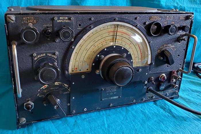
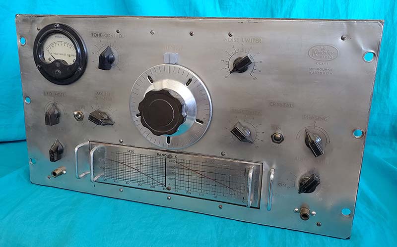
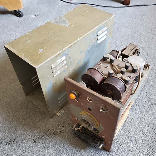
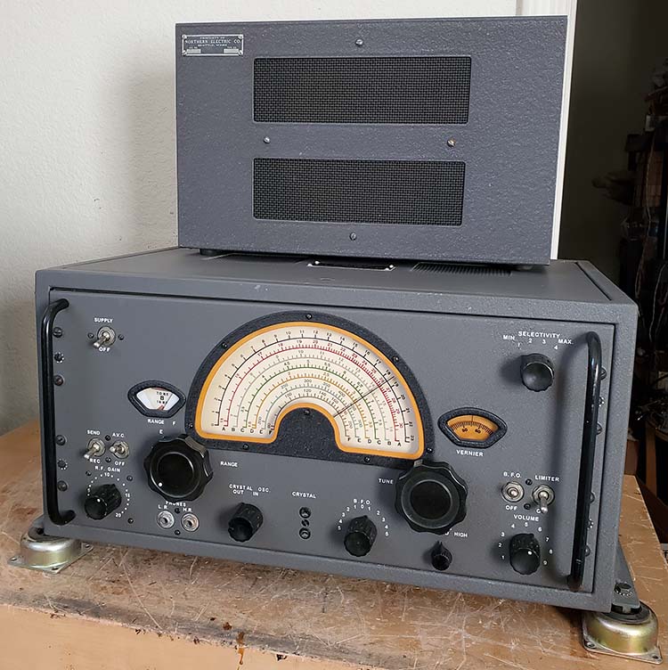
Oct. 29, 2020 - Workbench Revisit - 
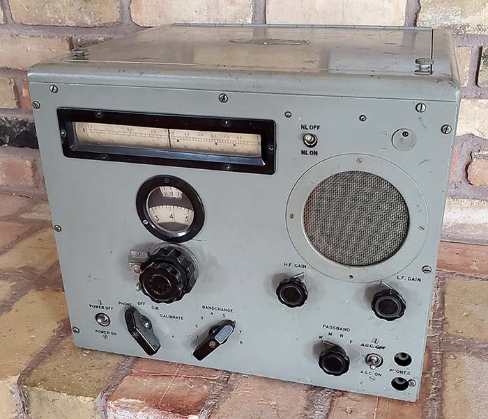
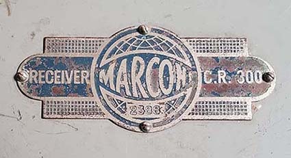
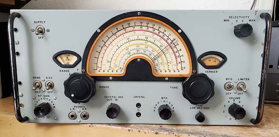
After using the C.R. 300/1 as a station receiver for about one month, a few minor problems required returning the receiver to the workbench for further "tuning up." The return work was going to require some disassembly mostly involving cabinet and bottom cover removal (and front panel dismount later in the "revisit.") 
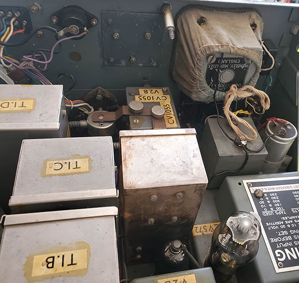
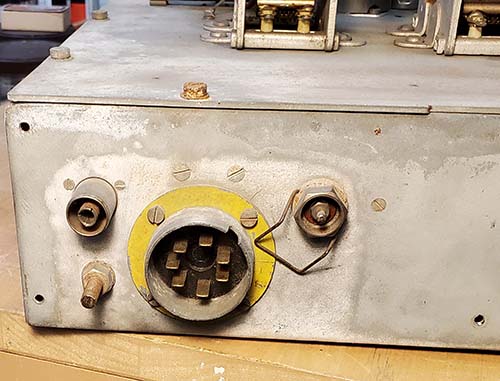
Installation of Tube Socket Shroud/Shield for DH63 - The first problem was mechanical because I had replaced the metal 6Q7 tube with the proper DH63 glass tube and that now required installing the correct tube socket shroud and tube shield. These parts had been removed years ago when the 6Q7 was installed. Installation was just a matter of tube socket screw removal, installing a correct style shroud and then reinstalling the screws. LF Gain Pot Problem - The second problem was a noisy AF Gain control (LF Gain) that seemed to be more intense since installing the DH63 (more info on this tube's performance, or lack of, in "DH63 Problem" below.) Access to the LF Gain pot was easy. I removed its back cover and cleaned with a DeOxit dampened Q-tip. The pot was reassembled and remounted. 
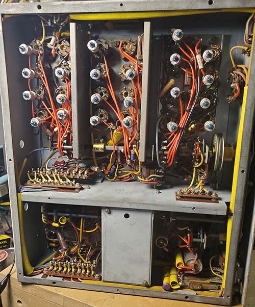
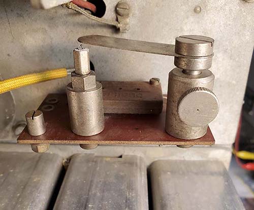
Band Switch Problem - Third problem was that I had to "rock" the band switch on Bands 6 and 7 to get full sensitivity. I hadn't cleaned the band switch, so that was done using a small paint brush and DeOxit. When doing the cleaning I discovered that the RF/ANT section bandswitch mounting screws were extremely loose. Both mounting screws required considerable tightening to have the switch always "inline" and to not move around when the bandswitch was operated. All of the other Bandswitch mounting screws were tight. The RF/ANT switch movement probably resulted in the misalignment in position 6 and 7 which the "rocking" of the Bandswitch knob would get the loose switch into the proper position. The IF band switch and the Passband switch were also cleaned. 
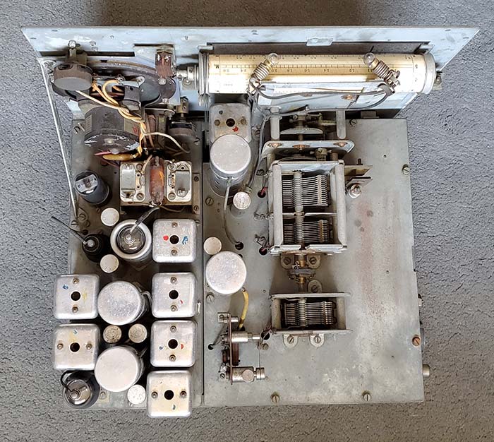
Re-Alignment of the RF Tracking - Since I had changed the RF amp tube from a KTW61 to the proper ARTH2, I performed a second complete RF tracking alignment. Since the installation of the ARTH2 improved the high frequency sensitivity so much I thought that the tube must have slightly different characteristics and a RF tracking alignment might show more improvement. Also, the first alignment was just a "quickie" - kind of a "roughed-in" alignment to make sure everything worked okay. I had used the slide rule frequency dial settings for tracking and that dial doesn't have any accuracy at all (even the manual states that the slide rule frequency dial is just for "reference.") The manual provides exact frequencies that correlate to 23.00 on the logging dial for the low end and 1.00 on the high end for each of the eight bands. To align the tracking accurately one has to use the logging dial since that is mechanically driven along with the tuning condenser. One has to use a 200pf dummy antenna load between the receiver and the signal generator on Bands 1, 2, 3 and 4. On Bands 5, 6, 7 and 8 a 100 ohm CC resistor is used for the dummy antenna load. The tracking adjustments were off by quite a bit, probably because of the way I did the initial alignment (a "quickie" alignment.) After alignment, I've noticed that the relationship of the logging dial/f versus the slide rule dial indication is that the upper and lower ends of the slide rule dial are off at the specified logging dial numbers but the majority of the slide rule dial indication is relatively accurate. 
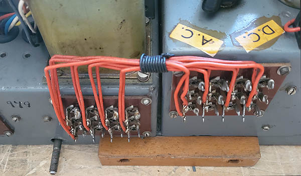
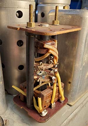
RF/Ant Coil #8 Problem - Another problem found while doing the alignment was that the RF/ANT adjustments wouldn't work on BAND 8. I found that one of the terminals on coil #8 had three different wires "wrapped and stacked" but the bottom wire in the stack wasn't soldered. I cleaned the non-soldered wire and then flowed new solder on the entire joint. Afterwards BAND 8 RF/ANT adjustments worked and could be aligned (and they were.) This improved BAND 8 sensitivity noticeably since before the RF/ANT coil wasn't "tuned." It's probable that this connection had been unsoldered since the receiver was built and the function of BAND 8 had relied on the wrapped mechanical connection but with decades of minor oxidation and dirt accumulation that mechanical connection had become non-conductive. HF Gain Pot Problem - The HF Gain pot had been giving erratic contact at the the top end of travel. Since the LF Gain pot cleaning had turned out so well I decided to do the same to the HF Gain pot. After dismounting the pot and removing the back cover an inspection revealed some surface cracking on the carbon element near end of travel. I cleaned the element and reinstalled the pot then set-up a temporary operation of the receiver which showed that the HF Gain still had a problem. Replacement of the HF Gain pot was unfortunately necessary. The junk box provided a very close look-alike 10K pot that was installed which corrected the HF Gain adjustment problems. The Front panel had to be dismounted for the HF Gain pot work so at this time I also lubed the IF switch cam with viscous grease. 
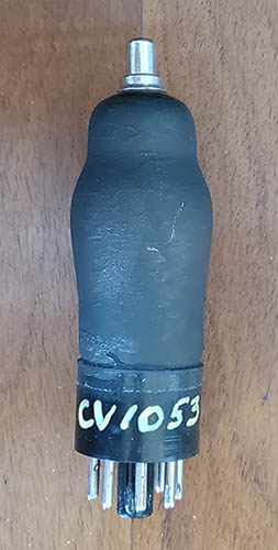
DH63 Problem - It was noted that when the receiver was connected to the station antenna the CW sensitivity seemed okay but when the BFO was switched off for AM reception the background noise totally disappeared and only very strong signals could be heard and they were badly distorted. This problem had developed while the receiver was on the workbench and it seemed to progressively get worse each time the receiver was operated. While I had thought the DH63 was a good tube (after all, it was sold as "used-tested good,") I replaced the DH63 with a glass 6Q7G. With the 6Q7G installed, the AM reception then had the usual background noise and sensitivity in both CW or AM was "back to normal." DH63 tubes have to be purchased from the UK and all examples that I've seen for sale are in "used-tested good" condition. I'm sure that this DH63 "tests good" but tube operation in a tube tester is usually just long enough to perform the test and that's all,...maybe one minute,...tops. It's quite different from the tube's operational performance in a receiver where the circuit parameters are quite different and length of time "powered up" might be measured in hours. For now, the 6Q7G will do fine. It looks absolutely correct since the "G" version fits through the tube socket shroud, it has the original style tube shield installed and most important - the 6Q7G is the recommended substitute for the DH63 in the receiver manual. 570kc IF Alignment versus Bandwidth Performance - In the copy of the C.R. 300 manual that I have the "Receiver Alignment - page (18)" is missing. This page details the IF alignment procedure. I had to experiment with some different adjustments to see what worked best. The best performance for the IF bandwidth function requires accurately aligning the 570kc IF with the receiver in the "N" Bandwidth position. The IF circuit boosts the gain when in "N" to compensate for the narrow bandwidth. If the 570kc IF is aligned in either the W or the M position then the gain boost for N is not apparent and the bandwidth doesn't seem to widen or narrow per the Bandwidth selection. The 570kc IF accurately aligned in the "N" position gives the user a wide bandwidth response in W, slightly narrower bandwidth in M and very narrow bandwidth but with boosted gain in N. This works out very well for CW, which was the commonly used mode during WWII. Since only a stronger AM Voice signal audio bandwidth would benefit in the M or W position, the slight reduction in IF gain is expected (but not really all that apparent) when these types of signals are tuned. 
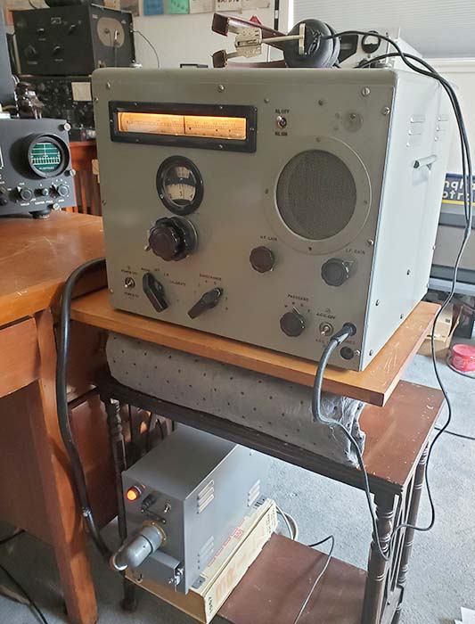
Workbench revisit completed on November 6, 2020 and the C.R. 300/1 was returned to the operating position paired with the Navy ART-13 transmitter. Combo used for Nov. 7th - MRCG net on 3.985mc with no problems. This combo has been used many times since then and the receiver is an excellent performer on 75M Phone. I've also listened to the various Chinese and Korean Frequency Marker Beacons on several different frequencies. Also, Gander Air on 10mc and Trenton Military on 15mc, both VOLMET aviation weather stations. So, the C.R. 300/1 is a good, dependable receiver that is able to provide reception many different types of transmissions. |
|
Canadian Marconi Company - CSR-5, CSR-5A History - The Canadian Marconi Company started out in 1903 as The Marconi Wireless Telegraph Company of Canada. At first, the company was part of British Marconi but soon, with Canadian government encouragement, MWT of Canada became an independent company. By 1919, after the WWI wireless ban was lifted, MWT of Canada created Scientific Experimenter Ltd, in order to sell wireless ham equipment. By 1922, they were selling broadcast radios. By 1925, MWT of Canada had changed their name to Canadian Marconi Company and entered into a cross-licensing agreement with Canadian General Electric Co. Ltd, Canadian Westinghouse Co. Ltd and Northern Electric Co., Ltd to "protect" their manufacturing patents to the exclusion of other Canadian radio companies. At the same time in the USA the so-called "Radio Group" operated a similar "cross-licensing" arrangement headed by General Electric with Westinghouse, AT&T, United Fruit Company and RCA as the members. Around this same time, CMC became involved in radio broadcasting. During WWII, CMC grew as a company and produced communication equipment for the war effort. In 1953, the English Electric Co.,Ltd. purchased a controlling interest in CMC (50.6%.) Since that time, CMC has had a multitude of different controlling companies, different owners and many name changes. The CSR-5 Receiver - In 1943, Canadian Marconi was contracted by the Royal Canadian Navy (RCN) to build a high quality receiver for their use onboard RCN ships. The RCA AR-88 had been approved for the Canadian military as the general purpose receiver but it wasn't specifically designed for use at sea (although it could easily do so.) The RCN wanted a "designed for sea use" receiver and wanted to do business with Canadian Marconi (even though RCA-Montreal built all of the AR-88LF receivers at that time.) The CSR-5 receivers were supposed to be ready mid-1943 but delays pushed delivery to either the end of 1943 or early 1944. Around 700 receivers had been ordered (and New Zealand wanted another 100 sent to them) so these receivers comprised the first of the CSR-5 receivers. Sometime in 1944, the CSR-5A was introduced. This version had several small changes inside and also to the exterior but basically the "A" was very similar to the earlier CSR-5. The CSR-5A was built up to 1945 with most of production occurring in 1944. |
|
The total production quantity of CSR-5 and CSR-5A receivers wasn't particularly a large number,...CSR-5 authority Jerry Proc estimates that possibly 700 CSR-5 receivers were built and perhaps 1000 CSR-5A receivers were built (but he cautions that this is just an estimate based on known serial numbers and that the exact method of CSR-5/A serial number assignment is not really known.) My CSR-5 shown in the photos is Type 110930Z (table cabinet type) with the serial number "394." The CSR-5 was used for several purposes, even though its intended primary use was supposed to be aboard ship. Shipboard use required extensive shielding in the receiver to allow its operation along side other equipment without causing interference or radiating the LO from the antenna and for the receiver's reception to not be interfered with by the operation of other shipboard equipment. The CSR-5 apparently met the <400pW LO to antenna requirement. But, the RCN found other uses for the CSR-5 such as surveillance and enemy signal intercept monitoring during WWII. Most CSR-5 receivers weren't installed onboard ships until the early 1950s. The later version CSR-5A was mostly built after the initial contract of CSR-5 receivers although it's possible that the production overlapped somewhat (probably mid-1944.) It's also possible that some CSR-5A receivers were built up into 1945 but the majority of receivers were built in 1944. |
Design and Circuit - The CSR-5 receiver's frequency coverage was in two sections, 75kc to 530kc and 1.5mc to 30mc, in six bands. Each scale on the large illuminated dial was color coded. There are two known variations that swap the colors assigned to Bands B and A (might coincide with the CSR-5A introduction.) Also, on most dials the Mauve color (light purple,) usually assigned to Band B, is actually gray. The CSR-5A replaced some of the 6SK7 tubes with 6SG7 tubes (in the RF and IF) as the major change, however there were many other minor changes in the cabinet vents style, power connector orientation, dial scale index style, etc. Many of the earlier CSR-5 receivers were retrofitted with the 6SG7 tubes which may cause confusion as to the receiver's original designation. Additionally, the manufacturing silk-screen was not changed for the chassis, so many CSR-5A receivers will have hand-modified 6SK7 to 6SG7 tube identification (rubber stamped ink usually but sometimes hand-written will be encountered.) When installed onboard ships, a dual shock mount system attached to each side of the cabinet. The two shock feet on each side were mounted to an angle bracket that was bolted to the lower part of each side of the cabinet. The CSR-5 has eleven tubes in the receiver with two RF
amplifiers, Mixer (also provides Xtal Osc function,) LO (9002 miniature
tube,) two 575kc IF
amplifiers (dual wave traps are in-circuit to prevent IF interference,) Crystal Filter (Selectivity positions 3 and 4) AVC/NL, Det/1AF, AF output and Voltage Regulator. The RF
Gain control is a stepped attenuator type with an average of about 10db
of change for each step. AF output is 2 watts into a 10K Z load for
loudspeaker, 500 ohms Z line audio and both Hi-Z (5000Z+) and Lo-Z
'phones (up to 1000Z.) The "Crystal" socket and "Crystal-IN" allowed
drift-free operation though a crystal-controlled local oscillator
function but the receiver still had to be tuned to the intended receive
frequency for the RF and Mixer stages to be "in tune." There was a Panoramic Adaptor connection provided
on the chassis (screw terminal connection.) Since a panoramic adaptor
could be used with the receiver, a carrier level meter wasn't required.
The panoramic adaptor had to have an input frequency range that would
accept 575kc but the manual never
specified where to find a manufactured panoramic adaptor with that input
frequency capability. Most panoramic adaptors had inputs that ranged
from 400kc up to 500kc since most receivers used the standard 455kc IF.
More specifically, the US Navy receivers RBB, RBC used a 400kc IF, the
Signal Corps Hammarlund Super Pro used a 465kc IF and the US Navy
National HRO (RBJ) used a 456kc IF.
Although the CSR-5 has the capability to allow panoramic adaptor use,
it's unlikely it was ever historically set-up that way. photo right: Chassis top of CSR-5 sn:394 |
![]() |
![]() |
The CSR-5 requires a separate power supply. The VP-3 provided 12vac Filament (series/parallel connections for all 6.3vac tubes except the BFO and LO that use series resistive loads) and +250vdc B+ with an input requirement of either 12vdc (vibrator PS) or 115/230vac. An AC only power supply was also available and designated as the WE-11. Two 6X5 rectifiers are used in the VP-3 bringing the receiver's total tube count to 13 tubes. Shown in the photo to the left is the VP-3 power supply. The two terminals with hex nuts installed are for the 12vdc input if the vibrator supply is desired. Internally, to change from AC operation to DC operation, first the AC plug has to be inserted into the dual slotted opening on the chassis next to the rectifier tube. This actuates a switch under the chassis, S-2. Then the six pin "option plug - PL-1" is removed from the "AC" socket and installed into the "DC" socket on the chassis. Then the toggle switch on top of the chassis is flipped to "DC." This toggle switch usually has a guard that has to be removed to actuate the toggle switch. Next, connect 12vdc to the + and - terminals and make sure a four-pin vibrator (12vdc) is in the socket. My VP-3 is set up for AC operation. The outputs to the receiver are two cables with Jones plug connectors. I've wrapped the two cables so as to handle like a single large cable. At the receiver-end, the cable has a single Jones plug (female) that mates with the Jones plug (male) on the rear apron of the receiver chassis. This is a modification (I think) from dual Jones connectors to a single larger Jones connector.
|
Two types of loudspeakers were available for the CSR-5. A table cabinet speaker and a dual rack mount speaker. The table speaker was an eight inch diameter speaker with a 10,000Z ohm to 8Z ohm matching transformer. The dual rack mount speaker is virtually unknown although it is pictured in the manual. It's not specified in the manual if the speakers had individual inputs (most probable) or if the speakers were connected in parallel with a single input (unlikely.) The photo to the right shows two CSR-5A receivers installed onboard the RCN ship Athabaskan in the early 1950s. Note the Marconi loudspeakers mounted on the bulkhead above the receivers. These are the standard table speakers that were available for the CSR-5/A receivers. Also, note in this installation how the shock mount feet are mounted directly to the underneath of the cabinet on the receivers. This certainly simplifies the shock mount installation and reduced the width of the receiver when compared to the width if the standard shock mount brackets were installed. The receiver in the center of the equipment is a version of the RAK made by RCA-Montreal, the TE236, that was used to monitor 500kc (although it tunes 15kc to 600kc.) The CSR-5 and 5A are found in a variety of different paint colors with the most common original color found being a wrinkle finish, light cream color with a slight greenish tint. Smooth finish gloss medium gray is found when the receiver was part of the CM-11 transmitter-receiver rack system. Light brownish-gray (beige) wrinkle finish is common in the stand-alone receivers. Many different shades of gray are often encountered and occasionally black wrinkle finish might be seen. Dark bluish-gray was also used at times. Along with the different colors, shades and texture variations will be found both black or white nomenclature (depending on the panel color used.) Some paint combinations are original but most of the really unusual variations might be from post-WWII military repaint jobs but, more often are from recent amateur restoration attempts where authenticity wasn't a primary consideration. Contemporary restorations involving repainting have to deal with the silk-screened nomenclature which usually complicates any refinishing plans. My CSR-5 SN:394 doesn't have the "Marconi" cursive script along with "CANADA CSR-5" in block letters silk-screened on the center area of the escutcheon. Originally, the CSR-5 did have the silk-screened lettering on the dial escutcheon but, when receivers were refinished by RCN depots in the 1950s and 60s, many escutcheons were painted and usually lettering was silk-screened. But, if the silk-screening was done at a depot, whether the receiver was a CSR-5 or a CSR-5A, the escutcheon was (always?) screened as "CSR-5A." All "block letters" were used without the "Marconi" cursive script. I didn't have any method to do an authentic lettering job and, since there seem to be some "non-lettered" RCN depot precedents, I left my escutcheon without lettering. |
![]() photo above: CSR-5A receivers aboard the RCN ship Athabaskan in 1952. photo from www.jproc.ca |
Re-Restoration - I obtained CSR-5 SN:394 around 2010 from fellow ham and collector NU6AM. The receiver had been cosmetically restored earlier by K6DGH, who had had the cabinet and panel powder-coated in a brownish-gray color that was substantially darker than the beige wrinkle that has been found on many CSR-5 receivers. NU6AM, Jim, had obtained the receiver in "unfinished" condition and needing some electronic work. Jim did a "re-cap" job that was not particularly sympathetic using "yellow jackets" and IC electrolytics. I believe that Jim wasn't too impressed with the finished CSR-5 performance and that's why he eventually sold it to me. At that time, I repainted the dial escutcheon black wrinkle finish because it had been flat black with white rub-on "block" letters that weren't original (and were obviously an amateur application.) I also made new cables for the power supply to receiver hook-up since the cables that had been used were made from very small gauge wires that didn't look sufficient to provide the power supply connections without a substantial voltage drop. I didn't do anything else to the receiver except use it for a short time and then put it on display in the Western Historic Radio Museum in Virginia City, Nevada. Fast-forward to 2020,...I had closed WHRM in 2012 and moved to Dayton, Nevada. The CSR-5 had been stored from the past seven and a half years in my "cool room" in the shop in Dayton (a well-insulated storage room where the temp extremes are from 30F to maybe 75F.) I had just recently gone through a Marconi R1155 and its impressive multi-colored arc'd dial got me interested in that large multi-colored dial on the Canadian Marconi receiver. I had to extract it from the "cool room" and bring it to the upstairs radio repair location to take a better look at it and reacquaint myself with how it performed. The CSR-5 still worked as it had,...okay, but seeming like it could do much better. The tubes tested okay but the band switch was very erratic and needed cleaning with DeOxit and a small brush. All controls were given the DeOxit treatment. The split-gears in the tuning gear box were stuck together so a flush with WD-40 loosened them and that eliminated the backlash. The BFO and NL toggle switches seemed non-functional but a "spray down the barrel" with DeOxit cleared up the internal oxidation that was causing the problem. I was sure that neither of the former owners had performed an alignment. If a full IF/RF alignment hasn't been performed, doing one will certainly improve performance significantly. The IF adjustments and RF L adjustments all have lock-nuts so be sure to loosen when adjusting and snug-up when finished (while watching the output meter to verify that the adjustment doesn't change with lock-nut tightening.) With this CSR-5, all of the alignment adjustments were far enough out that quite a bit of improvement was gained by the procedure, especially the tracking which now easily meets the 0.5% accuracy tolerance specification. |
I checked the "problem C123" location since this receiver was a CSR-5 with a serial number lower than 816. C123 was entirely missing. It's not a critical component but it should be present to take care of high frequency transients and protect the output transformer primary. Also noted were two of the connections to T4 (output xmfr) weren't soldered and several others were "tack soldered" connections. All connections to T4 were completely redone. I checked over all of the "new" solder joints under the chassis and corrected those that looked questionable. The RF Gain control connection to chassis needed to be redone. I shunted the "re-radiation resistor" in the antenna connection (it had been changed from original 1K to a 10 ohm carbon composition resistor, but I shunted it anyway.) That pretty much took care of the electro-mechanical rework. Cosmetically, K6DGH had mounted the CSR-5 data plate on the front panel. It should have been mounted to the top lid of the cabinet (as originally done.) The data plate was installed on the front panel with drive pins which required using a C-clamp and spacer to push the pins out of the panel. I remounted the data plate to the cabinet lid (original holes with screws and nuts hardware already present.) The non-original holes in the front panel were filled with epoxy and then touched-up with custom matched paint. It's worth noting that the data plate, while for a CSR-5 Type 110930Z, is SN:682, yet stamped on each side and on the rear chassis apron of the receiver is "394" which I assume is the actual serial number. Cabinet swapping during RCN depot repair might account for the discrepancy but a later collector "parts swapping" is more believable. That would be that the data plate isn't original to the receiver and cabinet. At any rate, I consider "394" as the actual serial number of this CSR-5. All of the front panel screws were fairly new but non-original type, black phillips head screws. The original screws used were round head slotted machine screws. I replaced all of the screws with the correct types. I wanted to set up the CSR-5 with the shock mounts. I found a set of shock mount feet (Barry mounts) on eBay and purchased the 1"x 1" mild steel angle locally. The angle brackets were built and then painted wrinkle finish using VHT Gray Wrinkle Finish. The VHT Gray has a lot of brown in the mix and it was a close match,...well, maybe one shade more towards gray but close enough. I've set CSR-5 SN:394 up as the station receiver with an ART-13A transmitter. Maybe not an original combination but both pieces are WWII veterans and work together nicely. photo right: Serial number "394" stamped into chassis's rear left-side |
![]() |
![]()
Canadian Marconi Company CSR-5 sn:394 from 1944 |
Performance - Overall, the CSR-5 is a good performer that is fully capable of operating as a station receiver in an amateur vintage military radio set up. The receiver is robustly-built and that provides excellent stability which is helped by the VR tube and filament loads on the LO and BFO tubes resulting in very little drift after a short warm-up. Sensitivity is competitive, especially if the receiver has been "gone through" and has had a complete IF/RF alignment and is used with a full-size, resonant (or tuned) antenna. Selectivity is very good if the crystal filter is operating correctly. It's a minor negative point that there's no front panel Phasing control for the crystal filter. The IF alignment instructions have C-64, the phasing trimmer, set to minimum bandwidth which is generally the desired function for a Crystal Filter. On the down side, the dial resolution is pretty vague, especially on SW. This is due to the wide frequency coverage of each tuning range and is typical (and expected) of any WWII vintage receiver. The logging dial and logging scale on the dial will provide an accurate method of frequency resetability. I'm using an eight inch Jensen speaker mounted in a Northern Electric loudspeaker housing that matches the CSR-5 quite well. To match the 10K output impedance, I'm using a 8K ohm to 8 ohm matching transformer spare that originally was for the Signal Corps LS-3 loudspeaker. T-R function is accomplished using the Send-Rec "AC receptacle" on the back of the chassis apron (or using the SEND-REC toggle switch on the front panel) utilizing the remote standby contacts on the T-R relay inside the ART-13 transmitter. The ART-13 also has a vacuum receive antenna switch for receiver isolation during transmit. The CSR-5 is a "heavy-weight" and when installed in the cabinet with the shock mounts weight is up around 75 pounds. Then add the VP-3 power supply at about 25 pounds (my cables are long enough so the VP-3 sets on the floor.) Update - Oct. 12, 2020 - I've been using the CSR-5 in combination with the ART-13A for a few of months now. It has proven to be one of my favorite WWII receivers to use. I've found it to be sensitive enough for 100% solid copy on all military radio net operations on 75M. Selectivity is good enough for dealing with adjacent frequency activity on all occasions. Audio quality is good and allows for excellent voice reproduction. I use the logging dial for accurate frequency reset. Minor points might be the AVC action which has a very slow "release time" which for CW is fine but for Voice could be a bit faster - very minor. Also, no antenna trimmer on the front panel (matched to the antenna during alignment.) A great receiver to use with fabulous bench presence. |
For More CSR-5 and CSR-5A Info - go the Jerry Proc's fabulous webpage located on his extensive website on Canadian Radio History and Royal Canadian Navy ships. URL is www.jproc.ca for the extensive website and www.jproc.ca/marconi/csr5a.html for the webpage specifically for the CSR-5 and CSR-5A. Also, an excellent article on restoring the CSR-5 receiver was written by Gerry O'Hara VE7GUH "Restoring a Marconi CSR-5 - A Canadian WWII Classic." There's a link on Jerry Proc's website to the SPARC location of that article that's in a pdf format. More info,.... 630M Operation? - I've been using the CSR-5 on 75M for several months now. It's set up with the ART-13A from SAAMA. It's the same ART-13A and CU-32 combo that I used on 630M a couple of years ago. I had a 630M hiatus due to an ART-13A power supply modification that involved using a separate linear 25A power supply for the 28vdc supply. It turned out that in CW, this 25A power supply would "kick out" its breaker immediately with the first "dit." Voice operation was better but still random "kick out" did happen. In November 2020, I purchased a used Lambda SWS600-24 switching supply that was rated at 25A and could be adjusted to over +30vdc. This power supply has solved all of the issues I had with using the linear supply. So, now 630M CW operation is possible again. A couple of years ago, I was using the Hammarlund SP-600VLF as the receiver and the receiving antenna was a homebrew 6' remotely-tuned loop. However, the SP-600VLF has been moved downstairs and I now have the CSR-5 as the station receiver. I needed to do a test of the CSR-5's MW reception performance. Also, the homebrew loop was history and I had been using a Pixel Shielded Magnetic Loop for MW reception. So, the test was to see what I'd receive using the CSR-5 and the Pixel Loop. Actually, performance was a real surprise. I tuned through the 300kc to 420kc part of the MW band to see what NDBs were present. Quite a few, with LLD 352kc in Hawaii and YXL 390kc in Ontario, Canada being noticed as pretty good DX. The "blowtorch" NDBs like MOG 404kc or QQ 400kc were extremely strong. Several of the 25W NDBs were received out to the midwest. So, this indicated that the CSR-5 was a capable receiver when using the Pixel Loop. How about what was on 630M? From 472kc up to 479kc was occupied by about five JT9 data signals, one of which was very strong. I did hear some very slow CW around 473kc but the signal wasn't on but a few seconds. What the test indicated was that 630M CW using the CSR-5 with the ART-13A and operating with a scheduled QSO is very possible. Due to the JT9 data users occupying most of the 630M band, calling CQ is usually a futile effort. Setting up a "sked" is the best method to assure a 2X QSO on CW. |
WWII Navy Gear - Part 1 WWII USAAF, USCG Comm Gear - Part 2 Home Index
|
Radio Boulevard
Western Historic Radio Museum
Vintage Radio Communication Equipment Rebuilding & Restoration Articles,
Vintage Radio History and WHRM Radio Photo Galleries
1909 - 1969
- 60 years of Radio Technology -
This website created and maintained by: Henry Rogers - Radio Boulevard, Western Historic Radio Museum © 1997/2025