Radio Boulevard
Western Historic Radio Museum


 WWII Radio Communications Equipment 
PART 2

U.S. Army Signal Corps Radio Gear
U.S. Army Air Forces Radio Gear
U.S. Coast Guard Radio Gear
Radiomarine Corp. Radio Gear
 WWII Radio Test Equipment


photo
: Women Marines Radio Op using two RAK receivers

WWII Communications Equipment - Part 2


U.S. Army Signal Corps

National Company, Inc. - NC-100ASD

National introduced a well-designed, direct-reading dial for their NC-100 series receivers in June, 1938. The "A" version dial had a mechanically articulated dial pointer that indicated the band in use when switching ranges and also included an S-meter as standard equipment. All of the other NC-100 features were retained, including the moving coil catacomb bandswitching, P-P audio, tone control, noise limiter (1940 models and later) and an optional crystal filter which was indicated by an "X" in the model designation. During WWII, the Signal Corps wanted a somewhat "militarized" version of the NC-100A. The receiver was designated as the NC-100ASD. It had special frequency coverage that included a medium wave band that tuned from 200kc up to 400kc. This required elimination of the AM BC band coverage since there was only room in the coil catacomb for five tuning ranges. The four higher frequency bands cover 1.2Mc to 30Mc. A single audio tube was provided, a 6V6, as was the 500 Z ohm output transformer that was to drive a matching loudspeaker that used an eight inch diameter Jensen with 500Z to 2.8Z ohm matching transformer. The loudspeaker cable was shielded to prevent RF pickup if the receiver was operated near transmitters. The probable contract number for the NC-100ASD is 9727-PHILA-43, dating from 1943. From reported serial numbers, the highest number is 948, it would appear that around 1000 NC-100ASD receivers were built. However, two NC-100ASD serial numbers reported have a letter "A" prefix serial number. The "A" might have been used in place of the numeral "1" with the actual SN of A578 indicating "1578" implying that over 1500 NC-100ASD receivers were built.  Shown in the photo is NC-100ASD sn: 194 with its correct 500Z ohm matching loud speaker.

After the war, the surplus market was certainly well-stocked with NC-100ASD receivers since apparently the Signal Corps didn't find much use for these receivers. Many ASDs were purchased surplus NOS at a price of $115 (1946 Newark Electric price) complete with matching speaker and manual. During the fifties and sixties, it was common to find the NC-100ASD used in many novice and "teenage radio amateur" ham shacks where economics dictated what sort of equipment was going to be in use. By then, ASDs were certainly "second-hand" status and priced quite reasonably. Performance was very good although QRM and lack of band spread probably limited most successful operation to 80M and 40M.

There was also an NC-100ASC version that was also designated as the AN/GRR-3. It appears that this version is similar to a militarized NC-100XA. There was also a version of the NC-100ASD that had a black background dial with silver numerals and a silver logging dial with black numerals. Unfortunately, the data plates were missing on the example seen so the designation is unknown.

The Navy also wanted their own version of the NC-100A - it was designated as RAO - more details in Part 1 - Navy equipment.


1945 ASP-1004 (same as BC-1004)

Hammarlund Mfg. Co., Inc. - WWII Military Super-Pro 200 Series

The military had several different Super-Pro versions built during WWII. Most versions were nearly identical to their civilian counterparts in the SP-200 line. As with most military contracts at that time, other companies besides Hammarlund built the military Super-Pros (Howard Radio being the most commonly seen.) The most popular military versions were BC-779(civilian LX) covering 100 to 400kc and 2.5 to 20mc, BC-1004(civilian X) covering .54 to 20mc and BC-794(civilian SX) covering 1.2 to 40mc. There were other assigned model numbers also, probably depending on the end user of the particular contract, e.g., the R-129/U that covered 300kc up to 10mc. Also, a suffix was sometimes added to the BC designation indicating the type of power supply that went with each receiver. Hammarlund's advertising implied that many Super-Pro receivers were also used by our WWII Allies. Internally, there are only minor changes made to the civilian Super-Pro for military use. Many of the capacitors are combined into "bath-tub" type units that mount on the side wall of the chassis. Also, the wiring harness uses stranded wire and sometimes the solder joints are MFP'd. All of the WWII military Super-Pros use a steel front panel that is copper plated under whatever type of paint was used. Generally, the steel panels were painted with a smooth finish and the stamped nomenclature was white filled. Panel colors range from black or gray to shades of green-gray or blue-gray. There were several variations in the construction of the power supply also with most military versions using heavy-duty, over-size transformers and chokes along with oil-filled filter condensers. Some power supplies had dual primary or multiple tapped primary power transformers to allow operation on 230/115vac or a variety of ac voltages around 230/115vac. Designations are usually RA-74, RA-84 or RA-94.

The military Super-Pro receivers are great performers with fantastic audio, although most are rack-mount versions which is a configuration not usually favored by collectors. Additionally, many of the military models are in deplorable condition today due their lack of appeal to hams during the last several decades. The receivers not only require the normal electronic restoration but a serious cosmetic restoration, too. Only recently has the WWII Super Pro found an appreciative group of hams and collectors that find the build quality and superior performance to be unmatched by most of its contemporaries. Shown is a military ASP-1004 (same as BC-1004) - probably destined for Allied use (ASP=Allied Super Pro?) from the later part of WWII. Note the eight holes around the outer edge of the panel - these are on all military Super-Pro receivers and normally were there for mounting the chassis dust cover. However, sometimes these receivers were installed in a military desk-top cabinet designated CH-104-A with the dust cover removed and screws and nuts installed in these holes (as shown.) Russia and Australia both built Super-Pro "knock-offs" during WWII, the KV-M from Russia and the AMR-200 built by Eclipse Radio in Australia.

The Signal Corps continued to support and use the SP-200 military versions post-WWI and well into the 1950s with upgrades to the the receivers and additions to the manual TM11-866. Improvement Kit MC-531 was a crystal oscillator kit that could be installed and would provide improved frequency stability with three selectable crystal controlled frequencies. There were other uses post-WWII, such as the AN/FRR-12, that utilized two modified BC-794 receivers in dual diversity with crystal controlled oscillators and crystal controlled BFO - all for reliable RTTY applications. The BC-794 receivers were professionally modified by Wickes Engineering and Construction Company in 1948. The MC-531 concept went on to be improved and incorporated into the standard design of the Hammarlund SP-600-JX receiver, which was introduced in 1950.

See "The Incredible Pre-War Super-Pro" web article for more details on military Super-Pro receivers, navigation link below.


the Hallicrafters, Inc. - Army-Navy AN/GRR-2

Most of the SX-28 and SX-28A receivers built for the war effort were standard Hallicrafters' production. In 1943, some SX-28s were built to a "heavy-duty" configuration that included a potted power transformer, dipped filter choke and audio output transformer and the return to the gear-driven bandspread tuning. These "heavy-duty" SX-28 receivers went to the Navy and the Signal Corps. Around April 1944, the SX-28A was introduced. It featured a series of improvements that had been incorporated into the very last of the SX-28 production. The major exceptions to these improvements were the High-Q Micro-set coils used in the receiver's new front-end. It was the installation of these coils warranted the designation change to "SX-28A." The U.S. Army Signal Corps and the U.S. Navy, wanted the SX-28A in the special "heavy-duty" build configuration and only these SX-28A receivers were given the designation of AN/GRR-2. From reported serial numbers it appears that the very first SX-28A receivers were AN/GRR-2 versions (the earliest reported SX-28A serial number is from an AN/GRR-2 receiver.) Also, from reported serial numbers it appears that only one run of AN/GRR-2 receivers were built (probably in late-March or early-April of 1944) and the total quantity of these receivers is around 300.

The AN/GRR-2 receivers are quite different from the standard SX-28A. The main differences are - the AN/GRR-2 uses a potted power transformer built by General Transformer Company, Korite dipped filter choke and audio output transformer and the gear-driven bandspread tuning system. This gear-driven bandspread had been used in the earliest versions of the SX-28 receiver (the gear drive had been replaced with a dial string drive in early-1942 SX-28 production.) The AN/GRR-2 also has wax impregnated IF transformers and bandswitches, MFP fungicide coating on the solder joints and special heavy duty nylon insulated stranded hook-up wire in the harnesses. Additionally, the AN/GRR-2 front panel was copper plated under the dark gray paint and the heavy-duty ball-end toggle switches have bakelite housings. The S-meter is a special unit that uses a bakelite case and is mounted using a special yoke system that mounts to the front panel with only two screws. All AN/GRR-2 receivers were originally configured as rack mounted receivers and utilize a steel dust cover with hinged lid that provides ample protection whether the receiver is actually rack mounted or used as a table top receiver. The Signal Corps had its own manual for this receiver - TM-11-874 - with more detailed information than the standard SX-28A manual (although errors abound in TM11-874.) The Signal Corps AN/GRR-2 shown is serial number HA-2703 and the fungicide dating is May 27, 1944. I rebuilt HA-2703 in 2010 but, other than the replaced capacitors and a repaired AVC transformer, the receiver is all original. Performance is typical for the SX-28A - great audio and lots of bench presence. I've use HA-2703 many times as the station receiver in a vintage military radio setup and it always has provided excellent service.


National Co., Inc  -  HRO-W

The HRO-M was essentially a slightly updated version of the HRO Senior that was introduced in 1941. The HRO-M was produced for the military during most of WWII with many of the receivers being sent to England. During HRO-M production, the lack of any identification for the control function of the toggle switches that operated the B+ and the AVC had been corrected by installing metal function "rings" around the toggle switches. The HRO-M also replaced the "pull switch" used for the S-meter with a toggle switch. Many HRO-M receivers were equipped with a Marion Electric 0-1mA meter with a white scale that wasn't illuminated. In 1945, the HRO-M was given a major upgrade that changed all of the tubes to octal types with all tubes being the metal octal variety with the exception of the 6V6GT audio output tube. Most of the components under the chassis were changed to JAN types. Additionally, all of the coil sets were given new aluminum silk-screened ID plates that were mounted on the front panel of the coil set to provide a frequency chart and a logging chart. National identified this receiver as the HRO-5.

The U.S. Army Signal Corps wanted a few subtle changes and the HRO-5 model built for the Signal Corps was dubbed the HRO-W. The minor changes were a data plate that specifies that the receiver is an "HRO-W" along with extreme moisture and fungus proofing (MFP) of the receiver. Most HRO-5 and HRO-W receivers will have the following characteristics,...the S-meter will be a non-illuminated DC MA meter with a white 0 to 1mA scale made by Marion Electric, the same company that supplied the standard illuminated S-meter for the HRO receivers. The "ball-handle" toggle switch used to disable the S-meter on the HRO-M was replaced with a "bat-handle" toggle switch. Like most military HRO receivers, the coil sets supplied were the "J" series versions for the A, B, C and D coil sets. These were "general coverage" only - no bandspread function on the JA, JB, JC or JD coils. The additional coil sets that were supplied with the HRO-5/W were standard general coverage and brought the total coils sets supplied to nine. The additional coil sets were E, F, G, H and J sets which increased to coverage from 30mc down to 50kc with a small section not covered (430kc to 480kc) around the IF frequency (456kc.) The power supply was normally the Type 697 supply that had selectable primary voltages of 115vac or 230vac. Typically, the military opt'd for an audio output transformer to remove the B+ from the speaker terminals but the HRO-W doesn't follow this pattern and the audio output transformer is mounted on the speaker, if used. Generally, headsets were used for reception but this depended on the installation and ultimate use of the receiver.

Note the receiver shown in the photo above,...not only is the interior of the receiver given the MFP treatment but also the knobs and switches. The MFP's yellow lacquer base gives the PW-D micrometer dial a distinct "olive-drab" color and imparts the impression that the knob skirts are brass. There is a silk-screen label under the lid providing MFP treatment information which is date-stamped "JUL 29 1945." National serial number on this receiver is K-127 while the Signal Corps data plate is stamped with the number "85."


BC-344-D Medium Wave Receiver - AC Operated

U.S. Army Signal Corps - BC-312, BC-314, BC-342, BC-344 Series - Various Contractors

The design of the BC-312, BC-314, BC-342 and the BC-344 receivers came from the U.S. Army Signal Corps in the late-thirties. Two versions operated on +14vdc utilizing an internal dynamotor (the BC-312 and BC-314) while the other two versions (BC-342 and BC-344) operated on 120vac utilizing an internal power supply unit, the RA-20. All versions of these receivers were stoutly built with rugged mechanical gear-driven tuning, robust wiring technique and made use of a steel chassis with extensive LO shielding utilizing a steel metal box. These receivers were built to "take a beating" and still function. While the overall size of the receivers is relatively small the weight is not - around 60 lbs - mainly due to the "all steel" construction of each receiver. Some aluminum is used (like the front panel) but the durability of the receivers is aided by the steel cabinet and chassis. All alignment adjustments have some kind of "tamper-proof" protection in the form of locking nuts, protective shields or plug covers. The BC-312, 314, 342 and 344 series of receivers were used extensively in ground applications from just before WWII up into the 1950s. The most common contractors were Farnsworth Television & Radio Corp. for both AC and DC operated receivers and RCA Manufacturing Co, Inc. for many of the early DC operated receivers.

The circuit is a nine-tube superheterodyne (ten tubes in the BC-342 and BC-344 which includes the 5W4 rectifier tube.) Two 6K7 RF amplifiers are used along with a separate 6C5 Local Oscillator and 6L7 Mixer tube. Two 6K7 IF amplifiers, a 6C5 BFO, a 6R7 duplex-diode triode for the Det/AVC/1st AF function and a 6F6 audio output tube complete the tube line up. Frequency coverage is from 1500kc to 18000kc in six tuning ranges for the BC-312 and BC-342. The BC-314 and BC-344 are medium wave receivers and cover 150kc to 1500kc in four tuning ranges. The BC-312 and BC-314 are operated on 12-14vdc (BC-312-NX version 24-28vdc op) and were intended for vehicular use, which could include trucks, cars, jeeps or tanks. The BC-342 and BC-344 included the RA-20 AC power pack allowing the receivers to operate on 110-120vac with the intended set-up being a fixed station inside a building but mobile stations were possible powered by a portable AC generator. The huge "trunk" connector protruding out of the front panel allows power input on DC versions (or filament voltage access on AC models,) telegraph key input, PTT and microphone routing, remote stand-by (in DC versions,) audio outputs and antenna relay function for interfacing with transmitters and other equipment. All versions of the BC-342 have a Crystal Filter while the DC operated versions will have a DIAL LIGHT control. Early versions of the receivers will have a wire dial index and a fixed 4000Z ohm audio output. All later versions have a plastic dial index and selectable audio output impedance of either 250 ohms Z or 4K ohms Z. Some versions allow access to the 1st AF output for earphone operation while the typical BC-344 set-up has both phones and speaker outputs tied together from the audio output transformer.

The receiver shown in the photo above is the BC-344-D built by Farnsworth Television & Radio Corp. This is an AC operated, medium wave receiver. Note that there isn't a Crystal Filter provided on this version and, since it's AC operated, there is no DIAL LIGHT control.

RESTORATION NOTES

Front Panel Removal:   If you are planning to restore one of the BC-312/342 or BC-314/344 receivers, be aware that the mechanical design does not consider ease of maintenance beyond changing tubes and routine alignment. Any of the receivers will be very difficult to disassemble, requiring the unsoldering of several connections and disassembly of other mechanical parts just to remove the front panel.

Mechanically, the Fast Tuning gear and flanged shaft have to be "un-pinned" so the gear and flanged shaft can be separated and removed from the front panel and interior gear panel to allow a front panel dismounting. Also, the front panel "trunk" connector wires must all be unsoldered to dismount the front panel and, additionally, there are some screws mounted to be backside of the front panel that must be removed. Even the two fuse holders must be unsoldered and removed before the front panel can be dismounted. In all, any work involving front panel removal is arduous.

The "phones" audio transformer is not accessible without front panel removal and removal of the BFO assembly. Dismounting any of the smaller assemblies is time consuming and usually requires unsoldering joints where the wire was wrapped one and a half turns before it was soldered. Additionally, there are many different length screws and standoffs that have specific locations so care must be observed during disassembly to keep everything identified for proper reassembly. Front panel removal is sure to result in several large piles of sorted screws and other parts along with several drawings and notes before reassembly can begin.


Shown in the photo above is the BC-312-N. This receiver has an onboard dynamotor that operates on +14vdc to provide B+ to the receiver. The tubes are standard 6 volt metal octals that are wired in series-parallel. There is no Crystal Filter provided but, since the BC-312 is DC operated, there is a DIAL LIGHT control. The DC voltage input is via the front panel trunk connector.

Other Problems:  Sometimes the OFF-MVC-AVC switch will have contact problems the prevent the receiver from powering up. The switch is a custom-built, stacked four level assembly that has no replacement other than another original switch. It's easy to access the power section of this switch since that section is not enclosed. Rather, it is protected by a fiber board cover that can easily be bent to access the contacts. Careful cleaning and readjustment of the sliding arm and contact point can usually get the switch working again. It seems that the contact problems are more due to oxidation and dirt since these two contacts are not sealed.

A common problem with later BC-312 et al receivers is lack of transparency and warping of the plastic dial index. Since the dial index assembly is mounted to the backside of the front panel with eight screws that are not accessible because of the dial assembly and mask, the front panel must be dismounted to replace this problem-prone part. The plastic is riveted to the metal bezel so removal of the deformed original will require drilling out the rivets. Making a new plastic dial index is fairly easy using thin plastic salvaged from "cheap" picture frames. This material is flexible but has some thickness to it and is fairly close to the original material. Scribe an index line and fill the line with white Artist's Acrylic paint, wiping off any excess so only the index has paint in it. Mount the new plastic index by either using rivets, fake rivets made from 2-56 screws and nuts or by epoxy'ing the new piece in place. Note in the photo of the BC-312 above that the dial index plastic has shrunk and warped to the point where the dial mask nomenclature can be seen over the .25" gap at the top of the dial cover. This is a "front panel off" operation to replace this piece.

IMPORTANT REASSEMBLY NOTES: When reinstalling the front panel screws it will be noted that all of the 6-32 screws are the same length but there are three different lengths of 4-40 screws. There are two "short" 4-40 that must be installed in the correct location otherwise the dial mask will be scratched when the band switch is operated. One "short" 4-40 is installed near the band switch knob and near the word "CHANGE" in the band switch nomenclature. The other "short" 4-40 is installed near the lower-left corner screw of the data plate. The four "long" 4-40 screws are for mounting the wire clamps that are made from fiber blocks. The remaining 4-40 screws are all the same length.

On the AC operated models, the RA-20 power supply uses a dual electrolytic filter capacitor. This is not an oil-filled paper dielectric capacitor as used in most other military gear. The RA-20 filter capacitors are often bad and require replacement. It's easy to use the original can to house the modern replacement electrolytic capacitors. The RA-20 is very compact and densely packed. There's no room for anything other than the original parts. So, stuffing the replacement electrolytics inside the original can is the good solution that makes use of the available mounting bracket and hardware.

The photo right is a Farnsworth-built BC-342-N. This is an early version of the "N" with the wire dial fiducial, non-selectable audio output Z (fixed 4K ohms) and the typical Signal Corps hand-written upgrade nomenclature above the ID tag. Note that this version does have a Crystal Filter provided (control is marked CRYSTAL PHASING.) 

Final Notes: Certainly the difficulty of performing any serious repair work or modifications has "saved" many of the BC-312, '314, '342, '344 receivers. Most of this family of receivers will be found without extensive modifications. Many are found in "all original" condition. Most receivers were heavily coated with MFP and this also has prevented the "faint-of-heart" from performing any serious rework to the receivers. Even the alignments are usually close because all adjustments were "locked" with various lock-nuts, plug covers or cover-shields. Quite different from the BC-348 receivers that were easy to work on and thus are always found with some modifications to originality. Sometimes you might find a BC-312 that has the RA-20 installed but this is easy to convert back to a stock, DC operated BC-312 as long as you can find the correct dynamotor, which isn't difficult.

All of this laborious restoration work will be rewarded as the BC-312/314/342/344 receivers are excellent performers with great sensitivity and plenty of audio when driving a matched speaker. The stock LS-3 is a good match for the 4K impedance of the BC-312 et al receivers.


Signal Corps U.S. Army  -  Panoramic Adapter BC-1031-C

Contractor: New London Instrument Co.

The Signal Corps US Army BC-1031-C was designed for 455kc operation. The earlier versions of the BC-1031 were built by Panoramic Radio Corp. and are black wrinkle finish with "toilet seat" covers over the adjustments. The "C" version was built by New London Instrument Co. and had a smooth finish satin black paint finish and featured a "sliding cover" (with thumb screw lock) to access the adjustments. The SC always had their own spelling,...note the BC-1031-C is a Panoramic Adapter ("e" instead of "o.") Interestingly, the SC decided to spell it "Adaptor" in the manuals.

These early types of panadaptors were not really designed for in-depth analyzing the characteristics of a signal. The intent was to use the panadaptors to easily and quickly spot signals that were outside the surveillance receiver's IF input passband (mixer output passband.) Once seen, the operator could then tune to the signal (which was seen on the panadaptor screen as the "peak" traveling across the graduated scale to the center at which point the signal is heard in the receiver.) The operator could generally tell what kind of signal it was from the display - either CW or AM. Relative signal amplitudes could be compared and specific signal frequency could be estimated using the graduated scale. Odd characteristics involving the type and level of modulation would be apparent. The sweep width was about 100kc.

There were also VHF panadaptors such as the BC-1032 Series. These units had IF inputs of approximately 5.2mc and generally would sweep around 5mc bandwidth. They are very similar in appearance to the BC-1031.


U.S. Army Air Forces

Aircraft Radio Communications Equipment


Signal Corps U.S. Army  -  RCA Manufacturing Company, Inc.
 

BC-224 Series and BC-348 Series
 

Various Other Contractor Companies


If ever there was a WWII military aircraft receiver that did "so much, so well, with so little," it was the BC-348. The double preselection superheterodyne receiver provided two TRF amplifiers, three IF amplifiers, Crystal Filter, front panel adjustable BFO, AVC-MVC, direct frequency readout on an illuminated, "band-in-use" masked tuning dial and an Audio Output stage that could be selected internally for 300Z or 4000Z loads. Unlike the proceeding aircraft receivers profiled above, the BC-348 was entirely "self-contained." All that was required was to connect the receiver to the +24vdc aircraft power buss, hook up the antenna, hook up the remote standby line and plug in the 'phones. The total weight of the receiver was about 35 pounds. Well-over one hundred and fifty thousand BC-348s were built during WWII making them one of the most common WWII aircraft receivers out there. It's unfortunate that over the past seven and a half decades hams (and surplus dealers) have managed to "cut and hack" almost every surviving example making it nowadays a real rarity to find an all-original, dynamotor-operated BC-348.
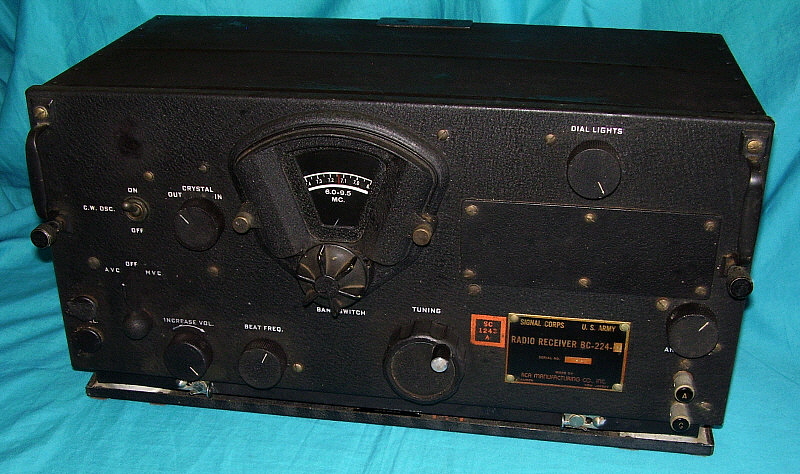
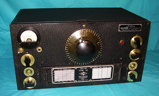

BC-224-H - 1942

RCA introduced the BC-224 Aircraft Receiver in 1935. It ran on the then popular 12 volt power systems used in most aircraft. The initial version of the BC-224 had the tuning dial on the left side of the front panel. This version is usually designated as the BC-224-A and the number produced was very small which was typical for pre-WWII military contracts. As aircraft power systems evolved, 24 volts became the standard voltage and that required changes to the radio equipment that was going to be installed in the newer airplanes. RCA redesigned the BC-224 to operate on 24 volts and this receiver was designated as the BC-348. With the redesign, both types of receivers had the tuning dial relocated more towards the center of the panel. The BC-224 continued to be built for installation into earlier aircraft while the BC-348 was produced for modern aircraft installations. Both receivers were built by RCA Manufacturing Co., Inc., a division of RCA-Victor that built all of the commercial and military radio equipment for RCA. When WWII began, several other radio companies became contractors for BC-348 construction,... Belmont Radio, Wells Gardner & Co., Stromberg-Carlson, to name a few. Only one contract for BC-224 receivers was built by another company other than RCA Manufacturing Co., Inc. and the last contract for the BC-224 appears in 1942. The BC-348 was produced through WWII and total quantity produced is certainly well over 150,000 receivers (over 50,000 receivers alone were produced by Wells Gardner & Company on just the "Q" model contract.)

The BC-348 operates on 24-28vdc with the high voltage (~+220vdc) provided by an internal dynamotor. It's quite likely that well-over 150,000 BC-348 (total of all versions) were built during WWII by many different contractors building many different versions within that time period. The circuit used eight tubes with the heaters originally wired in series/parallel for 24vdc operation (each of four 6 volt tube heaters in series would operate on 24vdc.) The early circuit provided two RF amplifiers, a Mixer, a Local Oscillator, an IF amplifier stage, a combination 2nd IF amp and BFO, a combination 3rd IF amp and Detector/AVC followed by a type 41 audio output stage (this was changed to a 6K6 in some versions.) These versions will have a 991 neon lamp acting as a regulator on the local oscillator and an antenna trim control. Construction makes use of four component boards resulting in extensive use of wiring harnesses. The Crystal Filter and BFO are in fully shielded cans. This early version is usually referred to as the "Grid Cap" version since these types of tubes are used. This early version was difficult to work on and was expensive to build. To reduce costs, the Q, N and J versions were introduced. These versions eliminated most of the component boards and used "point to point" wiring to reduce costs and ease rework. This version is called the "Single-ended Tubes" version since "non-grid cap" tubes are used. The later circuit used two RF amplifiers, a converter stage, three IF amplifiers, a duplex diode/triode provided Detector, AVC and BFO functions and a 6K6 provided the audio output. The later versions eliminated the shielded Crystal Filter, Antenna Trim control and the fully shielded BFO. The audio output impedance was internally selectable at "low Z" which was around 300 Z ohms or "high Z" which was around 4000 Z ohms (on later versions.) Some BC-348s will have a decal on the front panel indicating if the "low Z" was optioned. The dual dial lamps were adjustable for brightness and were wired in series through a potentiometer and fixed resistor. Frequency coverage was from 200-500kc (not on the B or some C versions) and 1.5-18mc. The military considered the two versions of the BC-348 to be interchangeable with virtually no difference in performance and operation.
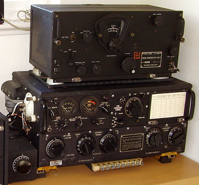
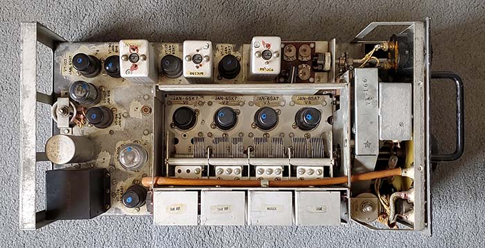
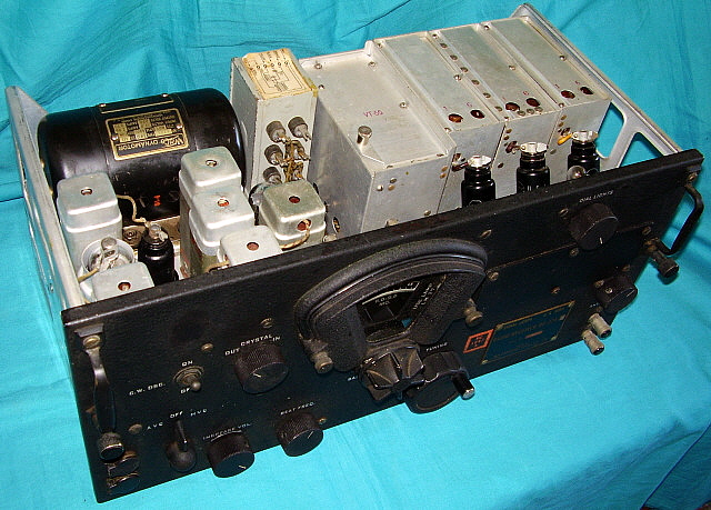

photo left
: Top of the RCA Mfg. Co. BC-224 chassis which is virtually identical to all of the "Grid-Cap Tubes" versions of the BC-348 chassis. Note that this BC-224 does have the proper DM-24 12-14vdc dynamotor installed.

A selectable crystal filter was also included in the circuit. If working correctly, the crystal filter can narrow the IF bandwidth to about 1kc wide, which counters the popular contemporary opinion that the BC-348's bandwidth is "broad as a barn." A correctly operating crystal filter can be a valuable QRM-fighting tool,...even on AM Voice. However, another option is to try and "dodge the QRM" with off-frequency tuning. Most SSB signals are about 2.5kc wide consisting of one sideband of transmitted information and no carrier. An AM signal is usually 6.0kc wide and, being double-side band, information is in each sideband along with the carrier. It's quick and easy to tune off frequency (either above or below) a few kilocycles, drop the SSB QRM off the edge of one sideband or the other and still recover enough AM audio for good copy. This is the method I use most often to dodge QRM using any type of vintage receiver, not just the BC-348. The Crystal Filter can be used for more severe QRM or when the QRM is on both sides of the desired signal. Tune the AM signal "on the nose" and the bandwidth will be significantly narrower. Also, another thing to try for severe QRM is to go to MVC and only use enough VOL (RF Gain in MVC) to allow copy.

When the receiver was installed on its FT-154 shock mount and installed in the aircraft, an eight pin Jones plug (SO-143) mated with a receptacle (PL-103) and cable that exited from the rear of the mount containing the 28vdc input, the remote stand-by relay function and an audio output line. The BC-348 was generally interconnected with the transmitter to control boxes allowing the transmitter's control relay to provide antenna switching, receiver stand-by and providing side tone monitoring which allowed for full "break-in" keying. Since there are so many variations, military collectors have generally divided the BC-348 into two groups, early types (B, C, H, K, L, O, P & R) with grid cap type tubes (usually called the "Grid Capped Tubes" version, or GCT) and the later versions (J, N & Q) with single-ended tubes (called the "Single-Ended Tubes" version, or SET.) Most of the very early versions (B and C) were rebuilt into later configurations, especially to add the 200-500kc band. These were rebuilt by Belmont Radio and re-tagged as "R" versions. Many different contractors built BC-348s but Wells Gardner & Co. probably built the greatest quantity of receivers and is the most commonly seen manufacturer.


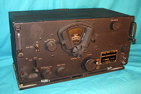
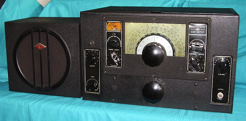
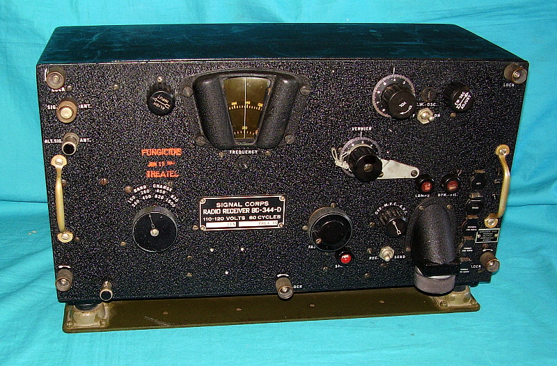
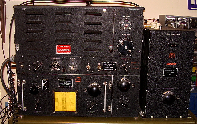
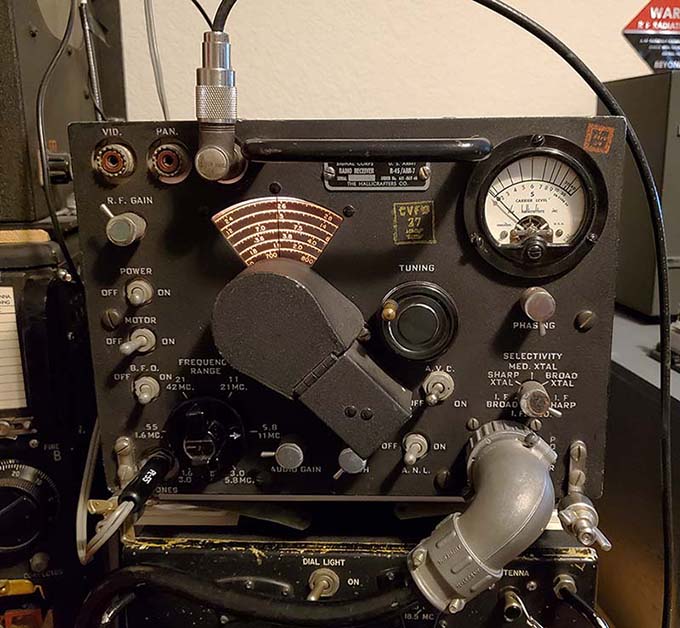
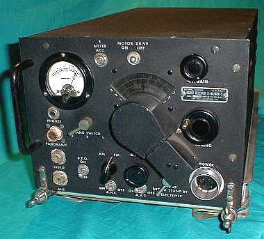
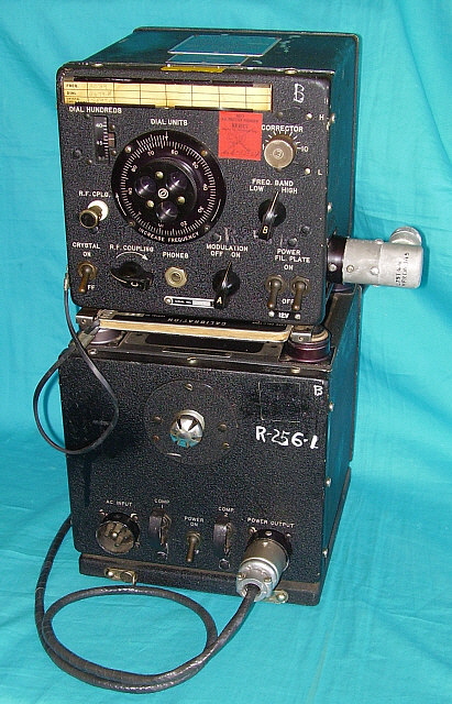
photo above: RCA Manufacturing Co. BC-348-C  - earlier "Grid Cap Tubes" version - ca: 1941. This BC-348-C does have the original style DM-28 dynamotor installed and the receiver is operational.


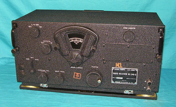
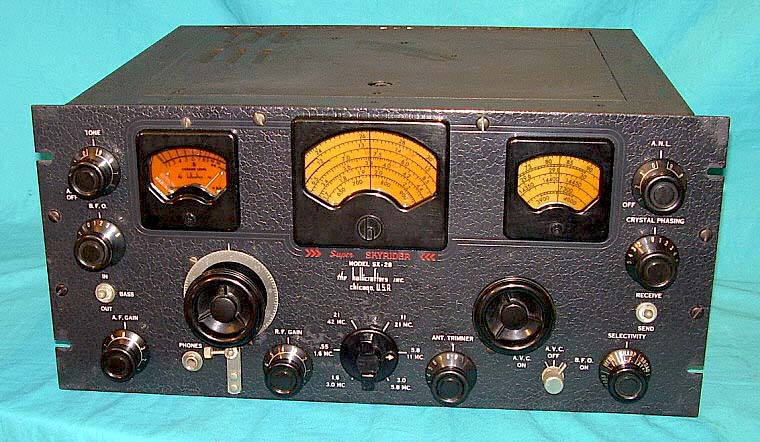
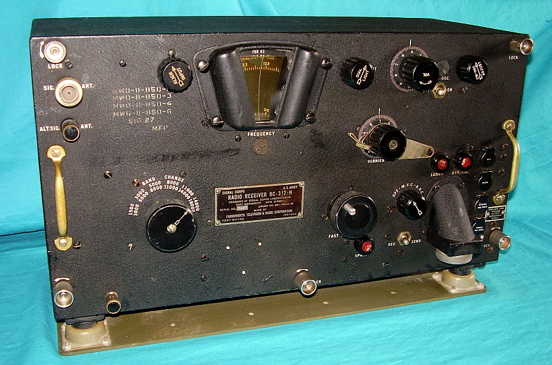
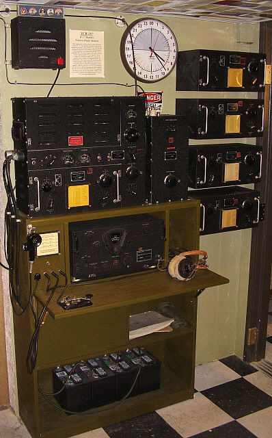
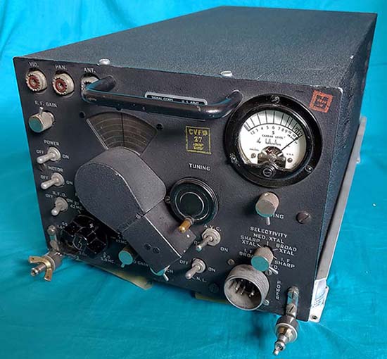
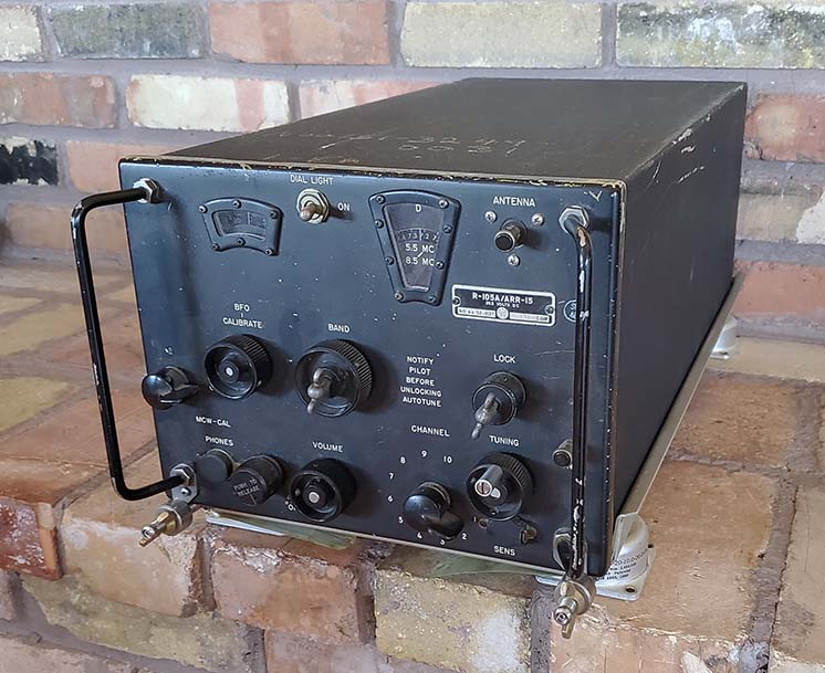
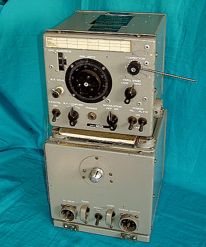
photo above: Wells Gardner & Co., BC-348-Q 1943 - this example is dynamotor operated. This one WG contract alone produced over 50,000 receivers. Note that these "Single Ended Tubes" versions eliminated the "ANT. ALIGN." (antenna trimmer) control that was located above the Antenna and Ground input terminals. Many other cost reductions will be found inside the Q, N and J versions. However, the great  performance is retained and these receivers are very easy to do any rework to.

A History of Hacking - The BC-348 became available as surplus almost immediately following WWII and was easily available for a couple of decades from many surplus dealers. Early purchases offered the receiver NOS in the original box. This allowed hams the ability to purchase a great performing receiver at a reasonable price - still in the crate for about $100. Many surplus dealer offered "AC power supply conversions" for as little as $15, so the buyer didn't have to do the work. The down side is that the dealers used the cheapest parts available and their installations show that little engineering thought (neither electrical nor mechanical) was applied to their AC conversions. Today it's almost impossible to find a BC-348 that hasn't been modified.

Typically, the dynamotor and filters were removed (and discarded) and an AC power supply was built onto the then vacant dynamotor chassis. Tube heaters were rewired for parallel connections. This mod was fairly simple and usually didn't compromise the receiver's performance too much (other than adding some hum to the audio output if the power supply wasn't designed correctly or wasn't well-filtered - which most weren't.) Unfortunately, most of the dealer power supply mods used a separate AC power toggle switch that resulted in a non-original hole on the front panel. Purists can't blame the just hams for shoddy mod design and workmanship because the dealers were actually charging the purchasers of the surplus BC-348s for the opportunity to destroy the originality of thousands of receivers. Additionally, all of the dealer-installed power supplies were just Pi-network filtered and as cheaply made as possible. Dual section filtering is necessary for proper hum reduction in the BC-348. Also, not realizing that there's a B- return for audio grid biasing, many "ham-ster modifiers" grounded negative leads on filter caps causing rampant hum in the receiver audio.

Certainly the "ham-ster" destruction of many of the BC-348 receivers was popularized by CQ magazine and their "Surplus Conversion Handbook" (there were multiple editions) in which page after page of "cutting and hacking" examples were presented. Every page seemed to promote the idea that the BC-348 needed "ham-level engineering" (after all, what did professional radio engineers that worked in the major radio corporations know about ham radio?) Adding an audio output section was a common mod. After all, what ham owned, or could afford, any sort of impedance matching transformer when they could build the mod using "junk box parts." The audio output mod called for the removal of the original audio output transformer which makes finding an original audio transformer today somewhat difficult. Removal of the 8-pin Jones plug power input connector or adding a useless S-meter were also common mods.

Additionally, many hams would sometimes drill the case with lots of .25" holes thinking the receiver needed extra cooling because of the added AC power supply rectifier tube. Somewhere along the line of destruction, the receiver base mount (the FT-154) always seemed to have been removed and discarded. Since the receiver's engagement pins presented a problem for "mountless" BC-348s, sometimes hams would drill out all of the pop-rivets and remove the entire receiver base and then add rubber feet to the bottom of the cabinet. Of course, this ruined the cabinet for future use if the FT-154 ever turned up. Decades of "ham-ster mods" have pretty much made an "all original" BC-348 a true rarity. Of the well-over one hundred and fifty thousand built during WWII, few examples have made it to the present time without some type of modification. However, with diligent searching it's still possible to find unmolested examples. However, not so rare and usually not so pricy are the receivers that just had the AC power supply thoughtfully and carefully added. These examples usually aren't too difficult to restore back to proper operating condition. The Grid Cap Tube versions have many Micamold-brand capacitors that will require replacement but the Single-ended Tube versions eliminated these troublesome capacitors and many of the SET versions can operate quite well on original components. Both types of BC-348s are great performing receivers if restored to original or when conservatively modified (a properly designed AC PS only.) An thorough and accurate IF-RF alignment and repair of the crystal filter are absolute necessities for top performance (and must be done before any critical comments regarding IF bandwidth are even considered.)

If you're interested in restoring your BC-348 or BC-224 receiver back to its original configuration with the installation of the correct DM-28 or DM-24 dynamotor, go to our web article "Rebuilding the BC-348 Family of Receivers" This article tells you about all of the "pitfalls" that might await you in this seemingly easy project. Also includes information on other aspects of the restoration of these fine performing receivers, such as building (or re-building) a minimally invasive AC power supply that operates the receiver correctly. Although the proceeding write-up seems to imply that original dynamotor operation for the BC-348 results in best performance, the receiver will also operate just as well (perhaps better) on a correctly designed and properly installed AC power supply.  
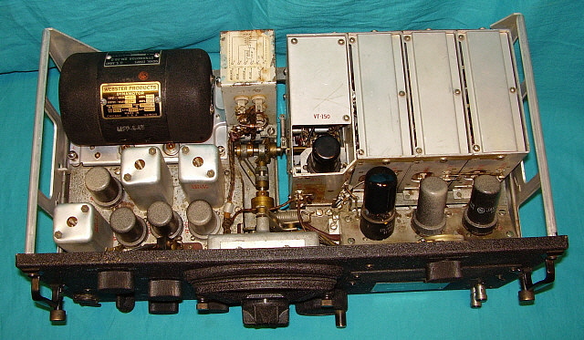
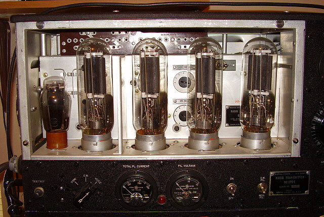
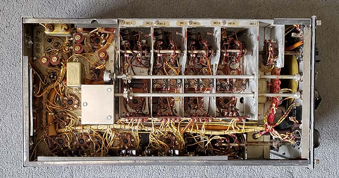
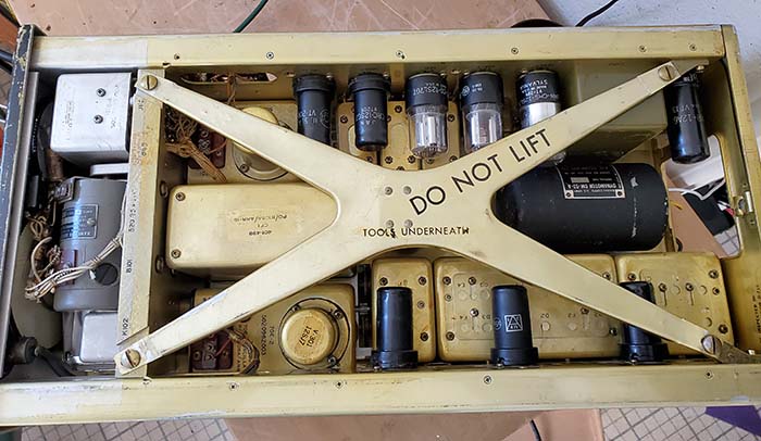
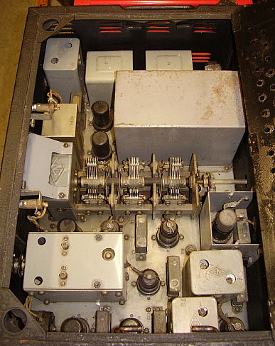

photo above: Inside the BC-348 "Single Ended Tubes" version. Note that the shielded cans in the IF section has been reduced from six to only three cans. Many other cost-reduction differences can be found when comparing the construction of the SET version to the GCT versions of the BC-348 receivers. Dynamotor is the DM-28 24-28vdc operation.


Signal Corps - U.S. Army Air Forces - General Electric

BC-375-E - Aircraft Transmitter

Though the BC-375 was initially designed in the early thirties (AA-191 transmitter) and utilized parts and technology from a decade earlier, it found a long-term usage with the Signal Corps due to its ease of operation and reliability. Its earlier kin, the BC-191, was the first version built from the mid-thirties on up to mid-WWII. Around the beginning of WWII, an airborne +24vdc version was necessary and the BC-375 became the designation for a slightly different transmitter for use in larger aircraft. GE got a manufacturing contract for close to 100,000 BC-375 that were built through the first half of WWII. Commonly used on B-17s, the SCR-287 was found on thousands and thousands of those bombers. Towards the middle of WWII, the ARC series of transmitters-receivers were introduced, along with the Collins ART-13A, to replace the BC-375. At the end of the war, thousands of BC-375-E transmitters remained unopened in their original crates (ready to flood the post-war surplus market.)

The BC-375 uses four VT-4-C triode tubes (type 211E) and a single VT-25 (10Y) triode with one VT-4 used as the Master Oscillator, another VT-4 as the Power Amplifier and two VT-4 tubes for the P/P Modulator. The VT-25 serves as the speech amplifier in the Voice mode (AM,) as a 1000hz oscillator in the Tone mode (MCW) and as a sidetone oscillator in the CW mode. Power is provided by the aircraft battery/charger system (+24 to +28vdc) and by a high voltage (+1000vdc) dynamotor (PE-73.) The BC-375 provides full break-in keying by allowing the elaborate internal antenna relay to control the receiver antenna and the receiver standby circuit. Additionally, external inputs via the PL-64 cable allow remote microphone and key operation along with remote power control. The aircraft was usually set-up to allow the pilot to also access the transmitter/receiver for various reasons. 


BC-375-E Transmitter with the BC-306-A LF Antenna Tuner


SCR-287 display at WHRM in 2009

After WWII, the BC-375 was available surplus, initially for about $125 (in the crate price,) but soon prices plummeted down to as little as $15. The various TUs were also available at "give-away" prices. This lead to many hams buying  the BC-375 for an economical way to get "on the air." Unfortunately, most hams tried to run the transmitter at full power on automotive batteries or tried to rebuild the transmitter into something that it was NEVER intended to be - a ham transmitter. The end result was a bad reputation that the BC-375 was unstable, sounded awful, created horrible TVI and was only useful as a resource for parts to build other ham projects. Though TVI was a major issue in the fifties, today's HD digital, uW signals routed though strong TV or satellite dish systems are not affected by the BC-375 operation. The transmitter can produce excellent "military" audio if it is carefully operated after a thorough checkout that includes a dynamic adjustment of the neutralization, using a good quality carbon microphone and, probably the most important,...not running the PE-73 dynamotor on batteries but running it from a high current, +28.5vdc power supply, e.g., the PP-1104.

The SCR-287 comprised a complete liaison radio station installed onboard various bombers and transports during WWII. The transmitter used was the BC-375. The other components shown in the photo to the left are the BC-348-Q receiver which does run on its original dynamotor from the battery supply, the Lionel J-47 telegraph key and the Shure Bros. T-17 carbon microphone. The speaker is an LS-3, although these were never used in the SCR-287 or onboard the aircraft. Four BC-375 Tuning Units are mounted in their CS-48 containers on the wall. The olive-drab console is not a WWII vintage item - it's homebrew. I designed and built the desk console as an easy way to display the BC-375/BC-348 and to have all interconnections neat and to have the equipment easily accessible. The console wasn't equipped with casters in Virginia City but I did install them with the move to Dayton. The panel to the left of the BC-348 has all of the remote connections for receiver audio output, receiver stand-by, xmtr CW sidetone select, xmtr microphone input and xmtr key input. The console features a fold-down desk, a sound-proof (almost) compartment for the PE-73 dynamotor and a bottom shelf for the four storage batteries.

IMPORTANT OPERATIONAL NOTE ABOUT USING STORAGE BATTERIES: The storage batteries NEVER worked correctly and were the major source of problems when operating the BC-375. The PP-1104-C military power supply/battery charger solves almost all of the operational issues with the transmitter. A high-current power supply and dynamic neutralization will cure 95% of the BC-375 operational problems. Batteries alone will never supply the proper input voltage of +28.5vdc to allow the dynamotor to spin fast enough to produce the +1000vdc B+ and to have the dynamotor armature rotating with enough inertia to stabilize that voltage under load. Less than +26.5vdc input will have the dynamotor output at about +900vdc and the slower rotation of the armature results in that voltage varying under load which results in FMing and non-symmetrical modulation on VOICE and "blooping" on CW. Trying to run the BC-375 only using batteries is a waste of time. If you must use batteries you can compensate for the low voltage instability by reducing transmitter power to about 40 watts, reducing the length of your transmissions and re-charging the batteries when in the "receive mode." This can produce an acceptable, albeit low power, signal. The PP-1104-C allows +28.5vdc at 50 amps input with no variation under load. The BC-375 will easily put out 75 watts 100% modulated and sound good doing it. Use a good quality, new carbon mike element for best audio results. 


For the ultimate information source on how to successfully operate the BC-375 "on the air" without enduring endless criticism of your signal's lack of audio quality, go to our web-article "Successfully Operating the BC-375 on the Ham Bands Today" - Use Home/Index below for navigation.

The End of Operational BC-375 Transmitters?

Shown to the right is the interior of the BC-375 showing the four VT-4/211E tubes along with the 10Y/VT-25 tube to the far left. The demand by audiophiles (actually by "vacuum tube investors") for the 211E has had a catastrophic effect on many future restorations or rebuild attempts of the BC-375 transmitters. It's not at all uncommon for a single 211E in good usable condition to sell for $250 (that's Fair Radio's 2021 price) and, if the tube is NOS in the original box, it would sell for double that on eBay. Power triodes that interest tube investors always sell for more in a set, so a good condition "quad" of 211E (necessary for a "tubeless" BC-375) could easily sell for $1200 to $2000. Luckily, these insane prices are only found on eBay and only when dealing with tube investors from Asia (or USA sellers that ONLY want to sell to tube dealer/investors in Asia.) Between military radio enthusiasts a more common price is about $125 a piece for a good usable 211E but that's still $500 for a quad if you have a "tubeless" BC-375 (check Aug 2021 update below.) The 10Y is still not expensive (except the Western Electric VT-25 version.)

There is a fairly common VT-4 substitute tube, the 805. However, although the 805 is an identical tube to the 211E, the external structure is different in that the 805 employs a plate cap where the 211E uses a base pin connection. There's ample room for plate leads without drilling holes so the incorporation of 805s into a BC-375 can be accomplished fairly easily. The only problem is that the tube dealers have now discovered the 805 also and the price of that tube has started to climb. 805 tubes are still cheaper than the 211E,...but for how long?

The high prices of power triodes like the 211E or the 805 have certainly halted or, at least, slowed down most BC-375 rebuilds. Today, the "standard condition" is to find most BC-375 are for sale "without tubes." Unfortunately, the high cost to "retube" a BC-375 has relegated "tubeless" transmitters to a "parts set" status. And, if a complete "tubed" BC-375 is for sale, the "tube investor" price will certainly be factored in.

The military radio enthusiast should take a look at the easily available ART-13 transmitter. These transmitters use tubes that are of no interest to vacuum tube investors. ART-13s are easy to rebuild, easy to get going and they produce a 100 watt carrier, 100% modulated with excellent audio.

UPDATE: AUG 30,2021 - Chi-Comm VT-4C/211E "new tubes" - Fellow BC-375/BC-191 enthusiast Charlie W4MEC mentioned in an e-mail that he had rebuilt a BC-375 for installation into a B-17 restoration that he equipped with Chi-Comm VT-4C/211E tubes and that these tubes were a fraction of the price of USA-made vintage VT-4C/211E tubes. The price was about $70 each for new tubes. Charlie indicated that these replica tubes functioned fine in the transmitters. In trying to find out more information as to the current availability of these new tubes, he checked the website https://www.thetubestore.com/shuguang-211  but it seemed the VT-4C/211E replicas are on "back order." Charlie related further that he had a friend that had a business that relied on his products being shipped from China. The friend was having problems getting his product because there is a shipping container shortage in China. The shipping container shortage has resulted in "who ever has the most money gets the container" sort of cut-throat hierarchy in the use of the available containers. The result is, if there is someone willing to pay more to rent the container, the items inside that container are unloaded and stored in a warehouse while the new renter loads and ships his product. It seems there are many items that were scheduled to be shipped but remain in warehouses in China. The order status of a set of replica VT-4C/211E tubes right now is "on hold" until they are back in stock and that could be a long wait. Check the link provided above regularly if you're interested in bargain VT-4 tubes.  


The "SAAMA Fugitive" ART-13A with a Belmont BC-348-R

ARC-8 Airborne Radio Gear
ART-13A Aircraft Transmitter, BC-348-R Aircraft Receiver

When the ART-13A transmitter and the BC-348 receiver were installed in an aircraft, the pair was generally designated as the ARC-8 station. However, to be absolutely correct for the ARC-8 designation, the ART-13 and the BC-348 should be operating in an aircraft from the +28vdc battery-generator buss and each should be powered by their respective dynamotors. That's not the case with the station shown to the left since it operates from a house and is uses AC power supplies that operate from the 120vac line. The ART-13A is a "SAAMA fugitive" that ended up at that facility, the San Antonio Air Materiel Area, in the 1950s. SAAMA was part of Kelly AFB and was given the SAAMA designation in 1946. SAAMA could and did rework almost any type of Air Force equipment. Unfortunately, this particular ART-13A seemed to be a problem for their technicians. Some how it made to the surplus market in "non-working" condition where it was sold. Some time after the sale it was disassembled. Then some parts were "cut out" and other parts lost. I obtained this ART-13A as a "basket-case" about fifteen years ago - actually three large boxes of parts along with several pieces of sheet metal. I thought it was just a parts set for quite a while. Eventually, I inventoried the parts and was amazed that I had almost everything to "build" an ART-13A. Lost forever were the three wire wound resistors located in the PA/MOD compartment but Fair Radio Sales supplied original replacements. The metal pocket for the cal book needed to be replicated. The audio module had been "gutted" so a replacement was purchased on eBay. The Plate/Grid/Batt meter needed to be replaced (from Fair Radio.) That pretty much was enough to get the SAAMA fugitive working up to a point. Apparently, at SAAMA, the meter function switch was replaced. Somehow, the SAAMA techs had mis-wired the switch causing the grid drive not to work (two wire positions swapped.) A few other problems were repaired and this ART-13A was pretty much resurrected from the junk pile. Over the years I've replaced the non-matching meters with a "matched set" of meters, added the O-17 LF Oscillator, added the calibration book and many other minor items that have added to the overall completeness of the transmitter.

The Belmont BC-348-R was obtained from a local ham. It was in excellent cosmetic condition and was fairly original only having had an AC supply added to replace the DM-28 dynamotor at sometime in the past. That PS was poorly designed and had excessive hum due to having the pi-filter input capacitor negative terminal connected to chassis. I built a completely new dual section filtered power supply that fit exactly into the dynamotor position and utilized the still present "dynamotor harness." The new PS used two chokes, three filter caps, solid state rectification and utilized the AVC-OFF-MVC switch to turn the receiver on and off. I also used the PL-103 rear connector so that the FT-154 shock mount could be used correctly. A full IF/RF alignment was performed. Also, the Micamold brand capacitors were replaced (notorious for shorting,...and two were.) It's a nice example of a minimally modified (AC PS only) "grid cap-type" BC-348-R.

There's no doubt that today the ART-13 is by far the most popular transmitter used by military radio enthusiast/hams in their vintage military radio stations. The ART-13 is easy to rebuild, easy to power up, it provides over 100 watts of carrier power with "high level" plate modulation in the AM mode and does this while maintaining a truly excellent stock audio response. The ART-13 started out as the Navy ATC and soon became the T-47/ART-13. It wasn't long before the USAAF wanted a version specifically built for their requirements. This slightly different transmitter was the T-47/ART-13A. The following write-up profiles both types of transmitters,...

Navy Dept. - Collins Radio Company  -  ATC, T-47/ART-13 (Zenith Radio Corp. was also a contractor)

Signal Corps USAAF - Various Contractors - T-47/ART-13A,
T-412/ART-13B, AN/ART-13 & AN/ART-13A


The Collins T-47/ART-13 is a 100 watt carrier output, AM-CW-MCW transmitter that was initially used in USN aircraft and later used in USAAF/USAF aircraft. The ART-13 could also be found onboard USN ships as the TCZ installation. There were even some vehicular uses for the T-47/ART-13. The T-47/ART-13 was developed from the earlier Collins ATC Navy Aircraft Transmitter that appeared around 1941. By 1943, Collins was building the T-47/ART-13 for installation in Navy aircraft and other applications. The USAAF also wanted to use the T-47/ART-13 and a very slightly different transmitter was produced for their use, designated as the T-47A/ART-13. Many of the T-47A/ART-13 transmitters were built by contractor Stewart-Warner and also some were built by Zenith Radio Corporation (Zenith also built some of the ATC transmitters.) Documentation was changed near the end of WWII to designate the transmitters as AN/ART-13 with the A suffix included. When combined with other equipment the set-up designation is for the entire installation. Hence, the combination ARC-8 describes the ART-13 combined with a BC-348 receiver along with the other necessary auxiliary equipment for a complete aircraft radio installation. The ART-13B was a modified ATC or ART-13 that installed a plug-in COMCO crystal oscillator that provided 20 HF and 4 LF channels. The mod also incorporated a frequency extension that allowed using the transmitter down to 1.5mc.

The T-47/ART-13 power requirements were supplied by a dynamotor that ran on the aircraft +28vdc battery/charger system. The aircraft battery buss supplied the +28vdc@10Amps necessary for the transmitter's tube filaments and relay operation while the dynamotor provided a dual output of  +400vdc and +750vdc. The dynamotor would have the two B+ levels connected in series for the HV Plate ( +1150vdc) below 20,000 to 25,000 feet altitude but a barometric pressure switch (located inside the dynamotor housing) would separate the outputs at higher altitudes and only allow +750vdc maximum to prevent arc-over. There were at least three types of dynamotors used, the DY-17, the DY-11 and the DY-12 (after WWII an improved DY-17A was produced.) The shipboard TCZ featured two types of power supplies, a 115vac operated power supply (of enormous proportions) that supplied the required +28vdc, +400vdc and +1150vdc directly to the transmitter. Additionally, the 115vac unit had a motor-generator that provided +14vdc and +28vdc (the +14vdc was required for relay operation inside the ac or dc operated TCZ power supply.) The 115vdc operated TCZ power supply used two dynamotors that ran on 115vdc input and provided +14vdc and  +28vdc output on one dynamotor and +400vdc and +1150vdc on the second dynamotor. The USMC had a vehicular set-up that installed an ART-13 transmitter with a BC-348 receiver that operated from the back of a Jeep and ran on the +28vdc battery system with HV provided by a DY-12 dynamotor. The antenna used was a whip.


photo above:  ART-13A "SAAMA Fugitive" with the CU-32 LF Loading Coil on top. I used this set up on 630M CW working into a 163 ft end-fed wire. This ART-13A is powered by the "DynaSim" AC power supply, a homebrew SS AC supply that uses a +440vdc and a +700vdc supplies in series to create the +LV (+440vdc) and the +HV (+1140vdc.) I made 2X CW QSOs on 630M as far away as Pennsylvania NO3M and South Dakota WØSD.


photo above: Not an Airborne Station - Navy-Collins T-47/ART-13 on top of a vacuum tube-based homebrew AC power supply in an amateur vintage military radio station. Note that this transmitter has the earlier style shock mount rails. Also the LFO is the Navy type O-16. The receiver is a Navy-Wells Gardner & Co. RAO-3. The Mill is WWII Underwood S I I. Although most of this equipment is from the same time period in WWII, it would not have been used together at that time. The RAO-3 was a surveillance receiver used with the S I I Mill at USN shore stations. This Navy ART-13 is the first T-47 transmitter that I rebuilt and got operating. The vacuum-tube AC PS is the first one that I built. This photo is from late-2020 before I had finished the ATC transmitter restoration. The last photo at the bottom of this ART-13 write-up shows the finished ATC set-up in this position now.

The T-47/ART-13 featured an advanced Autotune system that would automatically tune up to 10 preset channels selectable by a front panel switch. The Autotune system would tune the transmitter frequency and output network to mechanical presets that then would match a properly selected antenna. The Autotune cycle took about 25 seconds to complete. Switch position MANUAL would allow manual adjustment of the tuning without disturbing the Autotune presets.

The T-47/ART-13 uses an 837 as the variable frequency oscillator, two 1625 tubes are used as multipliers, an 813 as the power amplifier and two 811 tubes as the P-P modulators. There are also two small modules. One provides the audio amplifier and sidetone amplifier using two 6V6 tubes and a 12SJ7 tube and the other module, the MCW/Frequency Calibration Indicator, uses two 12SL7 tubes and a 12SA7 tube. FCI allows the operator to calibrate the frequency of the transmitter by providing a 50kc calibration signal derived from a 200kc crystal oscillator.

The transmitter frequency range is from 2.0mc to 18.0mc, however many Navy T-47/ART-13 transmitters were equipped with a plug-in Low Frequency Oscillator (LFO) module that allows the transmitter to operate from 200kc to 600kc or 200kc to 1500kc. Early LFOs (O-16) have a frequency range of 200kc to 1500kc in six ranges while the later LFOs (O-17) cover 200kc to 600kc in three ranges. The LFO module uses a single 1625 tube. There are some indications that the Navy preferred the 200kc to 1500kc LFO while the USAAF used the 200kc to 600kc LFO. Many versions of the T-47/ART-13 will have a blank plate installed where the LFO module was installed (along with a resistive load substitute for the LFO's 1625 filament.) After WWII, the USAAF/USAF didn't use the LFO module but the USN still did. This statement is according to the USAF Extension Course 3012 book on "Radio Mechanics" although this book is from the 1950s and may reflect the uses of the LFO at that time rather than during WWII.

LF operation does require an external tuner called a "loading coil." The Navy used the CU-25 or CU-26 while the USAAF used the CU-32. Also most installations on aircraft included a small Remote Control Panel that allowed the pilot to operate the transmitter from the cockpit. There are a couple of different remotes that could be used with the ART-13. Many transmitter installations also used three selectable condensers to allow easier loading into various antenna impedances at lower frequencies.

To the right is a photo showing the chassis of the Collins-built T-47/ART-13. This transmitter has the Navy version LFO installed. Also, this is a fairly early version of the transmitter so there are some differences when compared to the T-47A/ART-13 versions. Of note is the lack of an interlock switch which on the early versions allows you to easily operate the transmitter with the lid off. The module to the lower right is the Audio Amplifier unit and directly behind it is the 837 VFO tube. Behind the VFO tube is the FCI/MCW module (later three tube version) and to the left of it are the two 1625 multiplier tubes.The module in the center of the transmitter is the LFO. In the section at the rear of the transmitter, to the left side is the modulation transformer from which its plate leads connect to the two 811 modulator tubes. To the right of the 811s is the 813 PA tube. The left-center section of the transmitter contains the matching network and the LF relay (next to the LFO module.) On the far left is the vacuum TR switch and behind it is the keying relay. The round ceramic unit in front of the vacuum TR switch is the inductive pickup for the Antenna Current meter.

The somewhat later USAAF T-47A/ART-13 (ART-13A) version added some minor improvements to the transmitter with a vernier scale on the VFO Fine Tuning, a top lid interlock switch, a different bottom plate with built-in guides for the shock mount and a white ceramic insulator bell on the antenna connection being among the most apparent changes. There was also a T-412/ART-13B that added a COMCO selectable crystal oscillator in place of the LF module. The COMCO crystal oscillator normally has 4 LF/MF channels and 20 HF channels. All ART-13Bs are retrofitted earlier models and it is possible to find even early ATC transmitters that were converted to the ART-13B version.

The T-47/ART-13 and its variations had a very long life. Introduced around 1943-44, actively used during and after WWII and well into the fifties (sometimes found still being used well into the sixties and early seventies.) The USSR also produced a copy of the ART-13 that they used up well into the 1980s (the R-807.) Because of its long useful life, most T-47/ART-13 transmitters found today will have had many scratches and a few dents and paint scrapes. Non-matching modules are common and will be encountered with some parts having MFP applied and others that are bare. A book containing brief instructions and the calibration settings for specific frequencies was usually stored in the metal pocket underneath the transmitter. This book is also usually missing on most transmitters although the same information is in the standard manuals. Luckily, many tens of thousands of T-47/ART-13 were built and spare parts are very easy to find which allows for the fairly easy restoration and maintenance of these durable and potent transmitters.


photo above: Chassis of the Navy-Collins T-47/ART-13. The MCW/FCI module is the later, three tube version. The Collins chassis are usually painted gray and have a "winged emblem" embossed near the 837 VFO tube. When I first got this Navy T-47 it was partially disassembled and there were several boxes that contained many of the small parts. Everything went back together since it was just a reassembly job. Once completed, I built the vacuum-tube AC power supply which then allowed operating the transmitter. It has always operated reliably and is an example of what to expect from ART-13s that are in reasonably good condition.

Nowadays, the T-47/ART-13 has become one of the most popular aircraft transmitters being used in amateur vintage military stations. It can provide plenty of power with excellent audio. It's relatively easy to restore since there are many, many parts sets out there. Though the ART-13 can run on +28vdc and its original dynamotor, most users opt for a homebrew AC power supply. The +HV can be safely increased to around +1400vdc to provide even more output power and some brave users will run the HV up as high as +2000vdc (not for the timid and distortion might be encountered at this level of HV.)

After years of operating, repairing and restoring ART-13 transmitters, it's my opinion that the transmitter operates very well and quite reliably with an AC operated power supply that provides +27.5 to +28.0vdc at 15 amps minimum available current, +420vdc to +440vdc for the +LV and +1100vdc to +1200vdc for the +HV. The transmitter will easily and reliably produce 110 to 120 watts carrier output power on 75 meters - 75 meters is where most of the vintage military radio nets are located.

The Audio Module has a "fixed-level" gain setting that was designed to work with specific WWII vintage military microphones. The carbon mike bias resistor R203 was a 15K value that provided sufficient bias voltage for most "then new" carbon mikes. After WWII, many ART-13 audio modules were modified by changing the carbon mike bias resistor R203 from 15K down to 4.7K. In fact, the ART-13B schematic shows the R203 value as 4.7K. Audio modules with 4.7K bias resistors will have no problem providing plenty of carbon mike response. Check the value of R203 if you're having carbon mike problems. An easy way to achieve proper modulation levels is to use an Astatic TUG-8 stand with a D-104 or 10-D microphone "head" (with "DYNAMIC" selected on the Audio Module.) These mike stands have a built-in, adjustable gain amplifier that provides ample audio output to drive the fairly low input Z of the T-47/ART-13 (~ 250Z ohms.) An oscilloscope should be used to monitor the transmitter output when trying out different mikes as it will be very apparent on the 'scope whether proper modulation is being achieved. Due to the unbalanced, low reactance typical ham antennas used on 80 meters, the T-47/ART-13 will require an auxiliary capacitor connected to the COND terminal to ground for proper loading of these kinds of antennae. These external capacitors should be high voltage rated ceramic types. A fixed value 75pf to 150pf capacitor will work fine on 80M. 40M depends on the antenna used - a 40M dipole won't require an auxiliary capacitor if the C control is at 7 or higher for proper loading and antenna tuning (7 and above becomes a Pi-network.)


photo left
: Close to an Airborne set-up, sort of - this is the "Wasp's Nest ART-13A" - a Stewart Warner contract ART-13A SN: 2054 shown with a Collins R-648/ARR-41 Aircraft Receiver (1957 vintage.) Both the transmitter and the receiver run on their respective dynamotors and are powered by a PP-1104C +28vdc 50A power supply (actually a depot battery charger but it works great for high current voltage requirements such as running transmitter dynamotors.) Station location is out in the shop. This ART-13A was infested with "mud dabber" wasp's nests when found. Restoration (in 2016) of this ART-13A is detailed in Part 3 of the "Rebuilding the ART-13" article. Use Home-Index link below for navigation.


photo above:  USAAF T-47A/ART-13, aka AN/ART-13A - this is the "SAAMA Fugitive" back when I had just finished its rebuild, probably around 2011. Note the blank panel installed to replace the LFO. Also note that the two meters don't match. It's very common to find mismatched meters ART-13 transmitters and was probably a result of depot repair work, in this case from SAAMA (San Antonio Air Materiel Area, those guys worked on a lot of ART-13s.)


photo above: Chassis of the "SAAMA Fugitive." Note the "gold" appearance from the MFP coating (SAAMA laid it on thick.)

In case you haven't figured it out already, I have four working ART-13 transmitters that I use:
1. Navy-Collins - T-47/ART-13
2. SAAMA Fugitive - ART-13A
3. Wasp's Nest - ART-13A
4. SAAMA Survivor -ATC/ART-13

"SAAMA Survivor" - The photo to the right shows the latest (Feb. 2021) ART-13 restoration, actually a Navy-Collins ATC version that was MWO'd into the ART-13 configuration by SAAMA post-WWII. Six MWOs were installed but enough of the original ATC parts were still present to identify the transmitter's origins.

This Collins ATC/ART-13 was found in a rented storage unit in Carson City, NV. The ATC was at the very bottom of a six foot tall "stacking" of electronics gear. It also had several stripes of "hot pink" Latex paint applied on the top and front of the transmitter. The left side was "crunched" and the left grab handle broken with the entire central section missing. The right side also had a smaller "crunch" that actually was much more difficult to correct. Inside, the EMISSION switch was broken and needed to be replaced. The vacuum antenna switch was broken (shattered, actually) but, luckily, I had a NOS Sperti replacement to install. The 813 was missing and one 1625 tested bad. One glass tube in the CFI module was broken so it was replaced with a metal version. RF Plate meter flange was broken and a good "parts set" replacement meter was installed.

Lots of sheet metal work to straighten all of the panels. The lid was a disaster (after all, six feet of gear was piled on top of this poor transmitter.) Someone had cut a notch cut of the lip just to the left of the Antenna Current meter. The pink paint was everywhere but could be easily removed with Isopropyl Alcohol (worked because the paint was Latex.) Lots of "touch-up" with Mars Black acrylic paint.

Restoration is detailed in Part 4 of "Rebuilding the ART-13" write-up - use Home/Index below for navigation.


For copious amounts of detail and information on the Restoration and Operation of ART-13 Transmitters, including four schematics of different approaches to building an AC operated power supply, go to the web-article "ART-13 Transmitter - Restoration to Complete and Operational Condition"  - there are four parts to this write-up - go to Home/Index for navigation.


Setchell Carlson, Inc.  -  Model 524 Beacon Receiver

U.S. Army Signal Corps Designation:  BC-1206-CM
 

The Model 524 Beacon Receiver is a small size, light weight aircraft receiver that covers 195kc up to 420kc. The circuit is a five tube superheterodyne utilizing loctal type tubes. The receiver is entirely powered by the +28vdc aircraft battery-charger buss. No higher voltages are required to operate the 524. The "PHONES" output is 300 ohms Z although internally the output Z can be switched to 4000 ohms Z, if desired. The IF is 135kc. The tubes used are RF Amp 14H7, Mixer 14J7, IF Amp 14H7, Det-1st AF 14R7 and AF Output 28D7.

The 524 had a rather interesting use during WWII. These small receivers were installed into the instrument panels of airplanes that were going to be flown to specific destinations by WASPs (Women's Airforce Service Pilots.) This would generally be smaller fighter types of aircraft but did include larger aircraft as well. Some aircraft manufacturers had access to adjacent runways or the airplanes could be ferried from the manufacturer to either an airport or an export facility. Since the destination was known, the 524 provided a way to fly to a specific airport via the system of Airways and using Radio Range Beacons that provided continuous navigation signals. The pilot would use a homing loop to find the direction of the beam and then keep the airplane "on the beam" by course corrections during the flight. At that time, Airway Radio Range beacon stations also had other transmitters operating on an adjacent frequency that provided weather reports and other information necessary for piloting aircraft. Once the airplane was delivered, the 524 was usually removed from the instrument panel and returned to the aircraft factory where it was eventually recycled into another aircraft destined for delivery.

The 524 is very sensitive with a specification of 3uv for 10mw output. The receiver shown in the photo to the left does function quite well and receives many NDBs and other signals in the 195kc to 420kc range. However, the lack of a BFO does limit the reception to only fairly strong NDB signals. Since the original application was to receive Radio Range Beacons that were MCW signals, a BFO wasn't necessary. It's very small weighing only about 4 lbs and measuring 4" x 4" x 6.625". The four holes in the front panel surrounding the dial plate are tapped and are provided to allow mounting the 524 into a standard instrument panel opening (3.125".) Other manufacturers manufactured similar Nav-receivers with the same dimensions for the same purpose during WWII. 


R-45/ARR-7  SN: 732   ORDER NO: 631-DAY-44  Contractor: The Hallicrafters Co.

MFP Coated: 1944     Reworked: 20 OCT 1950 at SAAMA

San Antonio Air Materiel Area - Kelly AFB, Texas
 

Signal Corps USAAF - The Hallicrafters Co. & Belmont Radio Corp.
 
Radio Receiver R-45/ARR-7   SN: 732
 

The R-45/ARR-7 was an airborne countermeasures search and surveillance MF and HF (.55 to 43mc) receiver that was primarily used for visual analysis of enemy radar signals and the visual analysis of other types of enemy signals. The Panadaptor and Video Outputs were designed to feed into specific airborne versions of typical panoramic adapters and oscilloscopes. The oscilloscopes normally utilized external oscillators to create lissajous patterns for audio analysis of incoming signals (Video output is from the 6V6 audio stage of the receiver.) The panoramic adapters monitored the output of the Mixer stage of the receiver and provided a visual representation of the spectrum surrounding the receiver's tuned RF frequency (but down-converted to the IF.) This allowed the operator to "see" signals that were outside the receiver's IF passband and couldn't be heard - but they could be seen on the panadapter, allowing the operator to tune to the signal for investigation and to analyze its RF characteristics. The motor-drive tuning could be set up to scan just small segments of a particular band or span wide portions of selected tuning ranges. The motor-drive tuning would automatically reverse at each adjustable end stop so when "programmed" the receiver would automatically keep scanning the same selected frequency segment until the motor was switched off. The motor was powered by the aircraft battery-charger buss but the tube heaters and B+ are supplied by the PP-32 power pack that ran off of the aircraft's 115vac 400 cycle power. Besides Hallicrafters, Belmont Radio also built R-45 receivers on a 1945 contract. Interestingly, the Belmont built R-45 receiver S-meters are marked "the hallicrafters, inc."

Airborne SX-28A? - The R-45's circuit has a few vague similarities to the SX-28A, although considerably "stripped down" to the essentials and lightened for aircraft use. 12 tubes are used (not including the rectifier that is located in the PP-32 power pack.) Some of the similarities to the SX-28A are the use of the same Micro-set coils in the front end, double pre-selection above 3.0mc and the six selectivity steps with three utilizing the crystal filter. The differences from the SX-28A are a Noise Limiter that is just a clipper circuit (not a Lamb Noise Silencer,) use of a Re-radiation tube circuit, use of a VR tube, no bandspread, no antenna trimmer and the "militarily basic" audio output system which is just a capacitive coupling from the 6V6 plate to drive the headphones. The audio output wasn't intended for "pleasure listening" but was provided to drive a set of 'phones that were only necessary to aurally analyze signals in complement to the visual analysis of received enemy signals. Audio output was spec'd at 600Z ohms impedance.

The Re-radiation Tube - Double preselection receivers with additional shielding usually provided enough isolation of the LO to prevent excessive leakage to the antenna (the Navy spec was <400pW of leakage on the antenna terminal.) Apparently, even more isolation was needed for the particular function of the R-45 as a countermeasures receiver and the necessity of the receivers to mutually not interfere with the other measuring equipment. The R-45 has a "Re-radiation tube" added into the antenna input to block the LO radiation from leaking back into the antenna. The Re-radiation tube is a 6AB7 tube that has the antenna input capacitively-coupled to the grid of the 6AB7. The plate of 6AB7 has B+ supplied through the primary windings of the antenna coils. Essentially, the Re-radiation tube is a buffer stage with unity gain that's inserted between the antenna and the RF amplifier to reduce LO leakage onto the antenna input.

Signal Losses? - Like other Hallicrafters receivers, the SX-28A for instance, the two lowest frequency bands only use one RF amplifier and the Re-radiation tube is coupled to that single stage RF on those bands. The four higher frequency bands use both RF amplifier stages with the Re-radiation tube. Some users feel that the Re-radiation tube actually causes signal loss and results in reduced sensitivity (it should be noted that Band 1 will be somewhat "desensitized" by the Q-spoiler resistor R59.) It's normal for the stock R-45's S-meter to never exceed S-9, even with a RF signal generator connected directly to the antenna input "pumping in" a 1.0 vrms sine wave. However, when the receiver is in good operating condition with a full IF/RF alignment having been performed and connected to a resonant antenna, signal reception seems very good, easily able to receive ample 20M DX or pick-up Asian coastal marker beacons in the 25M region of the spectrum. Surprisingly, the manual vaguely spec'd the sensitivity at something less than 10uv.

Review of Modifications That ARE NOT Recommended - If the Re-radiation (buffer) tube is thought to be limiting signals, a simple experiment might be to unplug the Re-radiation tube and install a simple capacitive coupling between the grid and plate tube socket pins (making a plug-in adapter would be easy) to see if there's any real difference. Unfortunately, there are some circuit conflicts with this simple approach. Better results would require disconnecting one end of R2 to isolate the B+ from the primary coil windings, disconnect one end of R53 to isolate the AVC from the grid of the Re-radiation tube socket (which is the antenna input circuit) and install a jumper across C25 to connect the primary coil return to chassis. Then install a wire jumper from grid to plate on the Re-radiation tube socket. Coupling from the antenna input will have a 100K shunt to chassis and will be coupled to the primary coil windings through an 85pf capacitor. That would result in a fairly standard antenna input circuit to the antenna coils and then to the RF Amplifier stage. The downside is that without the Re-radiation tube or an antenna trimmer, the antenna impedance will have to be closely matched and will vary with the tuned received frequency.

It's unlikely that the reconfiguration of the antenna input with the elimination of the Re-radiation tube will do too much for the S-meter operation. The S-meter is in the IF amplifier plate line and is heavily shunted with a 100 ohm resistor (and a series 500 ohm adjustment pot.) It doesn't respond to strong signals with any enthusiasm by design. In the original airborne countermeasures installations, the S-meter really had very little useful function since a panoramic adapter was connected and could provide much more useful information than the S-meter. The heavy shunt was probably to reduce the possibility of "pegging" the S-meter during the testing and measuring functions during in-flight operations. If the ultra-conservative S-meter is a concern, it's possible to slightly increase the value of the 100 ohm meter shunt resistor to allow a little more current to flow through the meter coil. But, one should remember why the S-meter is set-up the way it is (besides, an S-meter is not an accurate measurement instrument but was only provided for tuning AM signals and a way to compare relative signal strengths - and then that's only in the AM-AVC mode - the S-meter is actually "turned off" when the BFO is turned on.)


photo above: R-45/ARR-7 SN: 732 (non-operating pose)


photo above: W7MS' R-45 is setup with the proper APA-10 Panadaptor.    photo by W7MS

Any of these mods, of course, aren't necessary and aren't recommended. They're only presented here for information as to why the modifications really aren't needed and aren't desirable. As always, better performance improvement can be gained by thoroughly checking out the receiver, by using tubes that test "as new" in a quality tube tester, by going through the entire circuitry checking for defective components (be sure to check all ERIE Corp. resistors for drift - they are notorious for drifting "non-functionally" out-of-spec after 75+ years of existence, luckily there are only a few in the R-45,) by troubleshooting to repair any non-functional circuits and then the real necessity is performing a complete IF/RF alignment. Most important to good sensitivity and low noise reception is to use a resonant or matched antenna (remember, there's no antenna trimmer.) A correctly operating stock receiver with a full IF/RF alignment will perform quite well, receive ample DX and allow Q-5 copy on the ham bands when used with a resonant antenna. It's very likely that the damped S-meter gives the operator the impression that the receiver isn't performing as it should. But, ignore the S-meter and you'll find that the receiver can provide solid copy even on very weak signals. Remember, the R-45 was intended to drive 600Z ohm 'phones, not a loudspeaker. You'll hear everything when using 'phones.

R-45/ARR-7 SN: 732 was thoroughly serviced and a full alignment performed but still S-9 was about the maximum that the S-meter would show and that was with a signal generator input. Typical "over-the-air" signals rarely exceed S-6 (Radio Havana on the 49M band at night - with the dominate signal on the band - will consistently "almost" reach S-6.) The receiver is very sensitive with the ability to perform very well using a "tuned-dipole wire antenna" up to about 18mc (about the same as the SX-28A.) Higher frequency operation would certainly be possible using a "gain antenna" such as a yagi or a quad. I haven't installed any modifications to my stock R-45 since I believe that it's operating per the "design intent" of the receiver.

NOTE: It seems obvious that the R-45/ARR-7 must have been the subject of a Surplus Conversion article (or an ER article) somewhere along its post-war history. It's very difficult to find any examples of the R-45 that haven't been "ham-stered" and literally ruined for any useful purpose,...well ,... other than for parts. Certainly the re-radiation tube "ham-ster myth" hack jobs seem to be the most common but removal of the motor-drive and original power connector are close seconds followed by audio output modifications. It's unfortunate that the R-45 has shared a similar fate of the BC-348 in that nearly all examples found will be compromised in some manner. It's likely that the "Airborne SX-28A" myth is responsible for many of the modifications that were efforts to rebuild the R-45 into something that it was NEVER intended to be,...an entertainment, shortwave listener, ham receiver, pleasure band-cruiser.

UPDATE: Aug 15, 2021 - I've been using R-45 SN: 732 as a vintage military radio receiver paired with another SAAMA fugitive, the "basket-case" ART-13A. Actual "on-the-air" performance on the 75M band is very good with all stations copied Q5 even though the S-meter's normal reading is about S-6 for most of the stronger AM signals. Despite what the S-meter indicates, the reception using the R-45 is excellent and even the very weak check-ins can be copied quite well. Selectivity is acceptable but due to the usual adjacent frequency activity I normally have to keep the SELECTIVITY on IF SHARP. Stability seems consistent with the age of the design and isn't a problem for ham band use on AM. For CW or SSB monitoring, frequency drift (LO and BFO) is normal for a 1940s design and doesn't cause any problem with copy. I use a matched 600Z ohm loudspeaker for audio reproduction and the audio output can be very loud. Complaints would be the lack of a remote standby function. However, the AC power supply's 6.3vac powers up the R-45 tube heaters as soon as the power supply is switched ON. Then the R-45's front panel POWER switch turns on the B+ and this switch can be used for a "standby" switch. Also, the depth of the receiver is typical of later aircraft receivers but it can be a problem on some benches. Depth is 20.5" plus a slight bit more for the shock mount depth.  NOTE: Several times, on the Vintage Military Radio Net on 75M, we'll have up to three different stations successfully using all-original R-45 receivers for net operations,....W7MS, KØDWC and myself, WA7YBS. It's a capable receiver,...in capable hands.

photo left: Top of the chassis. Front end is in the center, IF section top-center, Xtal Filter in front of IF section, detector, bfo and audio at the rear of the chassis. The rear pot adjusts the motor-drive speed. The pot lower-front is the S-meter zero pot. The metal tube just below the glass VR tube is the Re-radiation tube. The blue dots on the tubes are just my indication that I've tested the tube and it was in good operating condition.
 

photo right: Bottom of the chassis. Band switch is at the top. Next long shaft is the Audio Gain, then the BFO shaft. The BFO air variable capcitor is located in the shielded box. Note how the RF coils have been "locked in place" using brown sealing wax. Probably done at SAAMA (luckily, during alignment, only a couple of coils needed L adjustment.) Also, all that red paint on the wiring harness was done at SAAMA. 


Signal Corps USAAF - The Hallicrafters Co. - Radio Receiver R-44/ARR-5
 

This VHF receiver was generally paired with the R-45 HF receiver and provided similar airborne search capabilities. The design intent was to allow airborne search and analysis of enemy radar or other signals. The R-44 is a 14 tube superhet tuning from 27.8 to 143 Mc in three bands and receiving AM, CW or FM signals. Motor-drive tuning provided a "search" scanning mode. Like the R-45, outputs for visual indicators were provided. A special "stub" antenna was used (AT-38) and a separate power pack (PP-32) provided the power for the receiver (and added three more tubes, although these were to provide B+ for three individual receivers.) Sometimes this receiver is called the "Airborne S-36" based on its vague similarity to Hallicrafters' VHF receiver, the S-36.

Up to three combinations of the R-44 or the R-45 receivers could be powered by the PP-32 power pack that provided the heater voltage (6.3vac) and the B+ (+275vdc) but the scanning motor drive was powered by the aircraft battery system (+24vdc.) Additionally, the PP-32 operated off of 115vac 400 cycle provided by the aircraft's AC system.

Apparently, when the R-45 and the R-44 were sold surplus after WWII some of the dealers also offered a very well-designed power supply kit with all of the proper military connectors and an interconnecting cable. I was given one of these types of power supplies with this R-44 receiver I obtained from Bill Mitchell of Yerington, NV about 20 years ago. Mitchell's father had originally purchased the R-44 surplus (never issued) along with the power supply kit in the late-forties. The sheet metal work makes it obvious that the power supply chassis and cabinet were professionally built pieces. W7MS also has one of these types of power supply kits that came with his R-45 receiver, so they were a fairly popular addition to the surplus R-45/R-44 purchase. The power supply provides 6.3vac for tube heaters and +230vdc for B+. The power supply doesn't provide +24vdc to operate the motor drive. The power supply is housed in a professionally-made black wrinkle finish aluminum cabinet. I use this power supply for either the R-45 or the R-44.

r-44.jpg (22294 bytes)
R-44/ARR-5 VHF Receiver


1952 Collins R-105A/ARR-15

USN, USAAF and USAF - Collins Radio Company

R-105A/ARR-15 Aircraft Radio Receiver

The R-105/ARR-15 was developed late in WWII specifically for the Navy but it wasn't long before the USAAF and later the USAF also became major users. There were some versions built and installed in aircraft in 1945 but most of the receiver's career was post-WWII. Collins originally designed the R-105 for the Navy to be paired with the ART-13 transmitter. Since the ART-13 could be set-up to "autotune" to ten selected channels, it made sense that the new aircraft receiver should also have the same capability. The autotune function would allow either a radioman to change frequency at his location or, via remote controls (C-733/ARR-15,) the pilot or co-pilot (or anyone else setup with a remote) would also be able to select control over the receiver (and transmitter via its remote.) With the possibility of several remotes being in possible control of operation, priority was determined by having the last remote switched "ON" having "control" until another remote would be switched "ON" and that action would pass the control of operation to the remote just switched "ON" by switching "OFF" all other remotes. Each time a remote was activated, the proceeding remote was deactivated which left control only on the "last activated" remote.

The R-105 uses 14 tubes in a single conversion superheterodyne circuit that tunes from 1.5mc up to 18.5mc in six tuning ranges. The receiver is powered by the aircraft battery-generator buss at +24vdc to +28vdc with the rated input voltage at +26.5vdc drawing 8.5 amps when auto tuning and about 3.1 amps in normal operation (dynamotor instantaneous surge current is about 16 amps.) The B+ is supplied by an onboard dynamotor that provides +220vdc at 100mA. Only one RF amplifier is used along with two IF amplifiers. To maintain better stability, a VFO (PTO type 70E-2) that tunes 2.0mc to 3.0mc operates with a Frequency Multiplier to provide the correct combining and excitation to the Mixer stage. The IF can be variable from 450kc up to 550kc when using the BFO-CALIBRATION control but when set to the detent at "0" the IF operated at 500kc. In CW, the BFO provides a heterodyne for demodulation. However, the BFO control also operates the CAL 100kc CFI oscillator when in the MCW-CAL position so when the BFO is tuned off of "0," it turns on the CFI calibrator. When setting up an autotune channel, if the frequency 7225kc was to be set, then the TUNING and BAND were set to 7225kc and the BFO was set to +25kc. This would have the receiver responding to the 100kc CAL harmonic at 7200kc plus the +25kc offset so that a heterodyne was heard and was fine tuned to zero beat using the TUNING control (not the BFO.) The autotune controls were then locked and another channel selected and the procedure repeated for that channel's desired frequency setup. The differences between the R-105 and the R-105A are slight and involve an improved autotune and a few minor circuit and component changes in the "A" version.

IF Bandwidth in MCW/AM Voice - The IF bandwidth isn't adjustable and is usually considered by most AM operator's to be very broad (specs are 15kc at 6db down.) This really only affects AM Voice reception and was undoubtedly a design decision that must have been impart due to the mechanical nature of the "autotuning" and the repeatable accuracy of the system (although the autotune accuracy is excellent and generally < 1kc off the set point) along with the accuracy of the transmitted signal's channel frequency. If retuning a signal would be necessary that involved "unlocking" the autotune for the manual tuning function which then changed the autotune settings for that channel. These possible autotuning issues made it mandatory that the receiver reliably "come up" on the selected channel frequency with the completed autotune "stop" ultimately having the received signal within the IF passband. For Voice reception, a wide bandwidth could provide enough recovered audio for good copy even if the receiver or the transmitted signal (or both) were several kilocycles "off frequency." This allowed the radio op to leave the R-105 "locked." It's important to adjust the SENS pot when in MCW. If the SENS is adjusted to maximum the increased noise will make weak-signal detection difficult and will also tend to broaden the apparent bandwidth of stronger signals (strong AM signals are fairly broad anyway.) The SENS pot is not used in CW. 

The CW mode seems to have a much narrower bandwidth probably due to the BFO action (being a Navy receiver, CW was the primary mode of reception at the time.) Also, that the AVC is eliminated, the VOLUME control adjusts the RF gain and the audio bandwidth is narrowed rolling off the high-end at about 1200hz helps narrow the apparent bandwidth. When receiving CW, the BFO can be adjusted to compensate for off-frequency reception to optimize the CW signal.

The 24 pin Cannon Connector - The installation onboard the aircraft required an aircraft wiring junction box and audio phone jack patch boxes (as needed) along with the necessary remotes and cabling. The original shock mount also included the mating connector for the R-105's rear mounted input-output connector which was a large rectangular Cannon 24 pin male receptacle. Besides power input, audio output and a remote standby there are ten pins dedicated to the remote channel selection and a few other pins for remote priority sensing for the receiver. Since the mating connector was part of the shock mount which seems to have always been left mounted inside the airplane, most R-105s today don't have the original mating connector or the original type of shock mount. There are other types of shock mounts available that fit correctly but don't have the rear connector mounting bracket (the R-105A shown in the photo is installed on a newer "generic" Barry Mount aviation shock mount.) The 24 pin Cannon connector was only used in one other application that might be encountered, the ARC-2, so finding an original plug can be somewhat difficult. There are several methods to interface power and other required inputs and outputs, so the lack of an original Cannon plug won't present too much of a problem. In the case of the R-105A shown, the former owner had a delrin block machined and bored to accept the proper size Molex female receptacle pins. The holes were counter-bored to provide "non-movement" of the Molex pins (once inserted) when either pushing in the plug or removing it. Though all the parts for the plug were included in the purchase, I've never completed assembly of the plug since most of the R-105A pin outs are for using the C-733A/ARR-15A remote box (examples of which seem to be "unobtainium.")

Actually, about the only rear connector-plug wiring absolutely necessary for local operation of the receiver will be the +26.5vdc and chassis ground/-26.5vdc connections along with disabling the remote standby control line and maybe using the audio output line (instead of the front panel PHONES jack.) All other pins are for remote channel select and remote priority operations. Powering up for check-out, only pin 9 (Chassis, -26.5vdc,) pin 17 (+26.5vdc) and a jump from pin 3 to pin 22 are required for receiver-only operation. For a station setup, Pin 3 and pin 22 would be used for remote standby function with NC for receive and NO for transmit. Antenna isolation has to be provided (the ART-13 has an internal vacuum T-R switch for receiver connection to the antenna.) I had lots of spare Molex pins that were the correct size, so I just made up a test cable with two 14 gauge wires with Molex pins on one end for power and a 22 gauge jumper about 3" long with Molex pin ends to jump pin 3 and pin 22. For testing, this works fine (actually, unless a remote turns up, this setup works fine for operation in a vintage mil-ham station too except that the jumper from pin 3 to pin 22 has to be removed and two wires substituted and then routed to the ART-13 sending relay.) The proper size Molex pin is "HCS 125 Socket" with a Mfg PN: 18-12-1602 (or a Mouser PN of 538-18-12-1602.)

Dynamotor Servicing - After test operating the R-105A a few times, I noticed that the dynamotor seemed pretty noisy (the receiver was out of the case) and the dynamotor was running very hot. Normally, you always have to service any dynamotor since most of them have never been serviced in their entire existence. The old style grease used in the ball bearings at that time will harden with age and inactivity, resulting in the bearings running with a minimal amount of lubrication. Also, internally, most dynamotors will have a lot of brush carbon residue all over the inside and that carbon can be somewhat conductive if there's enough residue. Almost always the commutators will need thorough cleaning along with de-glazing and leveling their surfaces. The brushes will also need inspection for length and proper seating. This dynamotor's condition was as expected,...probably never properly serviced and with lots of carbon residue all over everything internally. Servicing requires some disassembly and consists of pulling both end bells and removing the brushes (mark for correct reassembly.) At this point, I tested how freely the armature turned. It didn't move freely at all and was actually fairly resistant to any rotation. With the brushes removed the armature should easily rotate with virtually no resistance to movement. This "resistance to rotation" was probably what was causing the over-heating of the dynamotor (more current required for rotation resulted in more watts dissipation in the form of heat.)

I proceeded with further disassembly by disconnecting the wires going to the brush barrel terminals, removing the two long screws that hold the bearing housings to the dynamotor body and dismounting each bearing housing piece. Now the armature could be taken out. The armature will have commutators on each end. I used 600 grit AlOx paper to clean, smooth and level the surface of the commutators and then washed with Isopropyl Alcohol. I then used a wooden tooth pick that was sharpened to clean out any residue between each segment of the commutators and then cleaned them again with alcohol. The ball bearings are a press-fit on the armature shaft but the bearings can easily be cleaned and flushed with WD-40 and then repacked with modern wheel bearing grease. Pushing the new grease into the bearing will force any remaining "old" grease out the back of the bearing and the old grease will have to be carefully cleaned off making sure to keep any grease residue off of the commutators. The dynamotor body was thoroughly filled with carbon deposits that all needed to be cleaned out. I used alcohol and a combination of small acid brushes and Q-tips to remove all the carbon residue. I cleaned the brush barrels, the brushes and brush connector terminals with alcohol.

I carefully reassembled the dynamotor except for the end bells. This was so I could see the brush to commutator contact and make sure there wasn't going to be any "sparking" which is an indication of a rough commutator surface or poorly fitted brushes. I didn't see any sparking during this test operation, so the end bells were installed and the dynamotor installed into its receptacle with the slide-clips used to "lock" the dynamotor in place inside the R-105A.

Rubber Mount Problems - The newly serviced dynamotor ran much quieter and a lot cooler. However, with a little bit longer operation time, the vibration noise progressively worsened and the vibration could be felt when touching the case. Out of the receiver, the dynamotor ran quietly although some minor vibration could be felt. I tried rotating the rubber mounts to see if that would help since they were obviously old and leaning to one side but this didn't do anything to reduce the vibration. Next, I inserted extra rubber cushioning between the dynamotor and the mount. This seemed to reduce the noise from the imparted vibration significantly. It seemed that the original rubber cushions were just worn out. I ordered new small vibration isolation mounts (the size is 0.375" square and 0.50" tall with 8-32 studs 0.190" long for mounting - easily available on eBay.) Once installed, the new mounts had the dynamotor setting squarely and noticeable higher off the mount. When operating, virtually no vibration can be felt on the receiver chassis. When installed back in the case and on the shock mount the operation is now quiet and no vibration can be sensed when feeling the case.
 

NOTE: Rubber Isolation Mount Distortion: I think this might be a common problem on the R-105A due to how the rubber isolation mounts were designed to work. In a normal set-up, the receiver would have been horizontal and rightside-up with the weight of the dynamotor directing a force downward vertically onto the rubber mounts, that is, compressing the mounts. Years later, with most receivers minus their shock mount and in a "storage condition," it became a common sight to see R-105A receivers "stored" vertically on their backs with the front panel facing up or, if horizontal, they might be upside-down or on one side or the other. This places the weight of the dynamotor being supported at a right angle to the rubber mounts. With enough vertical storage time (decades?,) the rubber mounts become distorted and stretch with the result being that they are no longer able to support the dynamotor correctly when the receiver is placed back into the horizontal rightside-up operating position. Replacement of the motor isolation mounts will be required and afterwards always try to keep the receiver rightside-up and horizontal (although the new rubber mounts should last decades.)


photo above: R-105A chassis (top) showing the Autotune motor at the left (front of receiver) and the dynamotor at the right (rear of the receiver.) This particular receiver has been given the MFP treatment hence the gold color of most of the metal pieces. Also, note the main PTO 70E-2 (lower PTO) and the PTO for the BFO (upper PTO.) Between the two PTOs is the crystal controlled CFI module. There are two tubes inside the CFI module, also one tube under the shield in each PTO. The lower three tubes are the RF/Mixer section and the upper six tubes are the IF/AVC/Audio section. The R-105A chassis is 20.5" deep which became the standard aircraft radio receiver size for the time.


Radiomarine Corporation Shipboard Radio Equipment from WWII (not built for the Navy)


RMCA AR-8506-B  SN:4387  from 1943

Radiomarine Corporation of America  -  AR-8506-B

The RMCA AR-8506-B was introduced during WWII with schematics dated November, 1942 and with the FCC approval for shipboard use dating from February, 1943. The AR-8506-B is a five band receiver capable of reception of LF signals from 85kc up to 550kc and medium/shortwave signals from 1.9mc up to 25mc. The circuit is superheterodyne and uses 10 tubes along with a NE-32 (G-10) neon lamp for voltage regulation (LO.) The IF is 1700kc in order to allow the receiver to cover the entire 400kc range without interruption. Much of the ship's communications were in the frequency range of 400kc to 500kc and a standard IF of 455kc would have a gap in frequency coverage from about 430kc up to 475kc due to the IF operating at 455kc. Usually, shipboard superheterodynes will have IFs that are in the AM BC band area since this region of the spectrum wasn't normally tuned by the ship's communication receiver. The receiver can be powered by 115vdc or 115vac and can also be powered at 230v ac or dc using an external resistor unit, the RM-9. Tuning uses a 30 to 1 reduction vernier drive (counter-weighted) and there is an additional "band spread" function using a separate control. A built-in loudspeaker is front panel mounted and can be switched off by the operator if necessary. The FCC approval for shipboard use indicated that the AR-8506-B's LO leakage to the antenna was <400pW and thus would not interfere with other shipboard radio equipment and would not radiate a signal of sufficient strength for enemy DF or detection. The U.S. Army Signal Corps issued a manual, TM11-875, giving the AR-8506-B the designation R-203/SR.

These receivers were integrated within a shipboard communications console, generally the 4U, that contained two transmitters, another receiver capable of VLF reception (AR-8510,) an emergency receiver (crystal detector receiver,) a power control switching system that allowed battery operation or ship's power operation, motor-generator operation, various alarms and other equipment necessary for radio communication at sea. Most 4U consoles were installed on Victory ships and other merchant ships during WWII.

Shown to the right is the RMCA 4U marine radio unit. Note the the receiver to the left of the typewriter is the MW-SW receiver, the AR-8506-B, and the receiver to the right of the typewriter is the LF receiver, the AR-8510. The two transmitters are mounted directly above the receivers. Photo is from Sterling's "The Radio Manual" Fourth Edition.

After WWII, the AR-8506-B continued to be offered by RMCA for maritime use on various types of ships. The post-war versions are somewhat different in appearance in that the individual celluloid control identification plates are replaced with a "raised letter" type of panel nomenclature. Additionally, the data plate was removed and the manufacturing information became part of the front panel nomenclature. The AR-8506-B shown in the photo below-left is from 1953 and shows how the later versions looked when installed in the table top cabinet (with shock mounts.) The earlier (WWII - from June 1943) style receiver, using the round celluloid control ID plates, is shown in the upper photo. Ship owner's reluctance to replace radio gear had the RMCA consoles and the associated equipment in-use well beyond their normal life-span with examples still in use as late as the 1980s.

The AR-8506-B has an internal 1700kc wavetrap. The wiring and adjustment of the wavetrap should be checked if BC signal leakage is encountered. The wave trap should be adjusted on Band 3 for minimum response with a 1700kc RF signal input to A1 on the antenna input of the receiver. If it is correctly adjusted and still there is BC signal leakage then using an antenna that is "tuned" for the specific frequency desired should be tried. This could be a resonant antenna cut for the specific frequency desired or an antenna with an antenna tuner. The "tuned" antenna will be selective and should reduce the BC interference.  Like a lot of RCA receivers, the AR-8506-B doesn't have a standby switch (either remote or panel.) Most shipboard radio operations are receive on one frequency and transmit on another frequency using separate antennas so a standby wasn't really necessary. To use as a ham station receiver operating on the same frequency as the transmitter requires either an antenna relay with good isolation for the receiver in "transmit" or you can also use an electronic TR switch. Separate T-R antennas are also a possibility. In all cases, you'll have to reduce the RF Gain and AF Gain or switch off the loud speaker if you're on Voice transmission to avoid feedback.

photo left: AR-8506-B SN:53139. The first two digits on many of the Radiomarine receivers will indicate the year of manufacture, in this case 1953.


photo right: Radiomarine LS-1 Loud Speaker SN:4475. The probable year of manufacture is 1944. The switch selects either low impedance or high impedance. DCR in low Z is 5.0 ohms and DCR in high Z is 640 ohms. This would imply that the nominal impedance would be about 10 Z ohms for low and about 8000 Z ohms for high. The case is made of 3/8" solid oak with dovetail joints. This example has the wood painted black but originally the cabinet was painted gray. The speaker is a 3" diameter PM and a matching transformer is also inside the cabinet. I'm not sure whether the LS-1 was for testing applications or if it was for use as a temporary loudspeaker. The cable is about three feet long with a standard 1/4" phone plug on the end. The knob may not be the original style. 


Radiomarine Corporation of America  -  Model AR-8510

The AR-8510 is a five tube regenerative receiver that tunes from 15kc up to 650kc in four tuning ranges. Two TRF amplifiers are used with a Regenerative Detector and two stages of audio amplification. The RF amplifiers use a combination of tuned grid and tuned plate with a three-section ganged condenser for tuning. The audio output can drive the panel mounted loud speaker or headsets. The panel speaker can be switched off if only a headset is desired for reception. The receiver requires a separate power source of which many types were available. Various types of battery combinations could be utilized with either the RM-2 or the RM-4 Battery Control panels. These functioned on ships that provided 115vdc or 230vdc power. If 115vac was to be used then the RM-23 Rectifier Power Unit (power supply) was used. There was also an RM-37A Receiver B+ Supply Unit that provided 90vdc output from the ship's 115vdc power. This was to be used if it was necessary to conserve the B batteries that normally provided the +90vdc for the B+. The AR-8510 requires 6.3 volts at 1.8A (AC or DC) and 90vdc at 15mA. The vacuum tubes needed are four 6SK7 tubes and one 6V6G or GT.

The AR-8510 was provided with a cabinet and shock mounts if it was to be used as a "stand alone" receiver. However, if it was going to be installed into a shipboard communications console (as most were) then the cabinet and shock mounts were not provided. Many AR-8510 receivers were part of the shipboard 3U transmitter console that included a 200W transmitter, an emergency crystal receiver, a battery charger switching panel and an automatic emergency alarm receiver. 4U consoles used the RMCA AR-8506 (a MW and SW superhet) and a 500W transmitter. The 5U console had both the AR-8506 and the AR-8510 installed along with all of the other auxiliary equipment. Mackay Radio supplied MRU-19 or MRU-20 consoles with their equipment installed.

The AR-8510 was approved by the FCC for shipboard use in 1942. The schematic drawings are dated 1943. The AR-8510 shown in the photo above is dated NOV 1944 and has a serial number of 2774. The AR-8510 serial doesn't follow the typical RMCA format of having the manufactured year as the first two digits of the serial number. Instead the month and year are stamped on the data plate. This particular receiver was installed in an RMCA console so it doesn't have a cabinet. However it does have a bottom cover that incorporates embossed dimples for feet that allow the receiver to set on a table without scratching.

Most of the WWII installations were onboard Liberty ships. Post-WWII use was for commercial shipboard use. Later versions of the receiver look like the B&W photo to the right. This is from the 1950 manual. Note the "raised letter" nomenclature which is not used on earlier versions. Ease of maintenance during WWII would have had the receivers fitted with the celluloid tags that could easily be removed for repainting the panel or replacement if damaged. After WWII, the "raised letter" panels were probably used since the receiver wouldn't have to endure the rigors of war-time use. Post-WWII use continued for quite some time with AR-8510s showing up on old oil tankers as late as the 1980s.

photo right: The AR-8510 as shown in the 1950 manual.


U.S. Coast Guard

Mackay Radio & Telegraph Co. - Federal Telegraph Co.  for  U.S. Coast Guard

Type RC-123

The Mackay Type RC-123 was built for the U.S. Coast Guard on Contract TCG-34199 and Order CG-80609 dating from 1942. The receiver is a six-tube, regenerative RF circuit that tunes from 15kc up to 635kc in four tuning ranges. The power to operate the receiver was supplied by ship's DC power for B+ (115vdc) and batteries for the tube heaters. It was also possible to operate the receiver entirely on batteries in which case dry cells were used for the B+ requirements and usually rechargeable lead-acid batteries for the tube heaters. It was also possible to operate the receiver entirely on 115vac. To operate the tube heaters on AC, a small 115vac to 6.3vac transformer was mounted inside the cabinet and could be connected into the circuit using the terminal strip located inside the cabinet. The tube heaters are connected in parallel and the two dial lamps are also part of this circuit (#47 specified.) The red-jewel pilot lamp illumination operates through the internal ballast in the 35Z5 tube and is also a #47 bulb. The Type RC-123 receiver is specified as a Mackay Type 128-AZ with two changes. First, the audio output tube's plate circuit is transformer coupled and provides a 600Z ohm output at the phone jack and at the audio output terminals available inside the cabinet (for routing to a console output or operator's desk jack.) If compared to the common Type 128-AY, that receiver's audio output was coupled via a plate capacitor providing a Hi-Z output. The other change is specific to the 128-AZ and refers to the 6.3vac transformer for the tube heaters that is mounted inside the cabinet (the "AY" version also has the tube heaters transformer.) A single TRF amplifier (6SK7) is used along with a "regeneration" tube (6J5) that amplifies the tickler coil response in the RF section to improve the feedback level. The regeneration tube's output goes to a detector tube (6SJ7) followed by a first AF amplifier (6SJ7) and then an audio output tube (6K6G.) No reception filters are provided for relief from static crashes or other atmospheric noise. "Mackay Radio" isn't shown anywhere on the receiver. The "triangular shield" logo is the only indication that Mackay was involved in production. However, at the bottom of the panel is "built by Federal Telegraph Company, Newark, N.J., USA" which indicates the RC-123 pre-dates the FTC name change that happened during the early part of WWII.


National Company, Inc. for U.S. Coast Guard

  Type R-116

The USCG Radio Receiver Type R-116 was built on contract TCG-33675 with the Order Number of CG-80265. This contract was issued before WWII began for the USA with a date of May 15, 1941. Interestingly, the R-116 chassis is similar to the later USN RAO chassis in that an extra RF amplifier section is added to the rear of the receiver (April 1942 contract date for the RAO-2.) This contract dates the double-preselection upgrade for military National NC-100XA variants to pre-WWII and certainly must have affected the USN RAO evolution also. The R-116 uses eleven tubes as the RAO does however the circuit has several differences, uses different tubes and has several parts that aren't found in the USN RAO receivers.

The frequency coverage is different from the RAO with the R-116 covering 1.5mc to 27mc in six bands (RAO used a five-band catacomb.) This frequency coverage per band is spread out more than the NC-100XA or RAO receivers. The six bands required a different catacomb that was like National's NC-200 receiver that also used a six-band catacomb. The coil forms used in the catacomb are ceramic rather than National's normal coil form material (R-39.)

The catacomb band switch gear drive is very different in that the band switch knob shaft is coupled into a gearbox that rotates a shaft that goes back to the middle of the catacomb where the gear-rack is mounted to engage the pinion gear that's on the shaft. The RAO/NC-100XA had the rack mounted in the front of the catacomb driven directly by a short shaft and pinion gear from the band switch knob.
The front panel layout is significantly different with circular nomenclature plates (similar to the NC-200) used for all controls. The dial bezel is dramatically simplified when compared to the RAO. The R-116 doesn't have an S-meter. The Crystal Filter has just three positions, OFF-1-2. Additionally, the bar knob-operated dual toggle switches found on the NC-100XA/RAO were changed to single toggles on the R-116, each with its own nomenclature plate. The locations for the controls are quite different from the RAO. The band-in-use indicator is the same as the RAO receivers except for the six positions (Bands A thru F) rather than five positions. The dial is very similar to the RAO except for the bands' frequency scaling. Flanking the tuning knob are two logging charts. 

Note the four threaded holes in each corner of the panel. These were for an optional rack mount adapter that looks something like a picture frame with grab handles on the front. Rear support was provided with threaded holes in the bottom rear corners. It was also possible to use a cradle-type shock mount on these receivers (the cradle-type shock mount was also used on the RAO-2 thru 6 receivers.) The cabinet is very similar to the RAO-2 thru 6 in that it is made up of several pieces rather than the one-piece cabinets that were used on the RAO-7 and 9 receivers.

The R-116 lacks an internal power supply requiring that the receiver operates from a separate AC power supply (rack mount dual supply) or from a DC source such as batteries, motor-generator/battery combo or other types of shipboard power sources. Voltages required are 6 volts for the tube heaters and +230vdc for the B+. A four wire power cable exits the rear of the receiver. Audio outputs are 300Z and 600Z. Serial number on the R-116 shown is 46. Also reported is R-116 SN: 103.

Tubes Used - RF1-6K7, RF2-6K7, Mix-6K8, LO-6J5, IF1-6K7, IF2-6K7, Detector-6J5, AVC Amp/Rectifer-6SF7, BFO-6SJ7, 1stAF-6J5, AFOUT-6V6,

Components - Photo to the right shows the chassis of the R-116. The circuit below the tuning condenser is very similar to the NC-100XA or RAO with the exception of the oil filled bypass capacitors that are mounted to the chassis. Above the tuning condenser, where the AC power supply normally is on the RAO or NC-100XA, are several unusual components. The large box is an audio filter that can be switched in from the front panel. The left choke is also part of the filter. The transformer to the right of the choke is the audio output transformer. To the left of the two tubes in front of the filter is the Relay. It appears that this might be a remote speaker on/off relay.


Special Purpose Receivers for Various End Users

RCA's AR-88 Series was in the preliminary design phase when WWII broke out in Europe. It was rushed to completion so it could be supplied to England where it was used primarily for intercept. The AR-88 was also supplied to other WWII Allies with very few receivers actually remaining in the USA during the war. When the AR-88s were being exported on Lend-Lease, RCA made it clear they didn't want the receivers returned to the USA after the war. Consequently, many were destroyed after the war ended. But, many have survived in the UK and in Europe. Almost all early versions are NOT in the USA. Most USA AR-88 receivers are from late in WWII or are post-war production. Certainly the majority of AR-88 versions were produced during WWII but the significantly reduced post-war production continued on until the early-1950s.


RCA AR-88D ca.1944

Radio Corporation of America  -  AR-88 Series from WWII

     includes: AR-88D, AR-88LF, CR-91 - also Triple Diversity Receivers DR-89, RDM 

RCA's most successful communications receiver was the AR-88. Designed in 1940-41 by Lester Fowler and George Blaker (and rushed into production because of WWII requirements) the AR-88 was a 14 tube superheterodyne that covered .54 to 32MC in six tuning ranges and featured incredible sensitivity (even up to 10 meters), excellent stability and high fidelity audio (from a single 6K6.) Most of the production was sent to England, Russia or other Allies during WWII using Lend-Lease which accounts for the scarcity of the early versions of the receiver in the USA. The AR-88 was used extensively in Great Britain during WWII mostly for enemy signal intercept. RCA and Radiomarine Corp. of America also used the AR-88 and its variants in their own installations for various purposes. Even the US Military used some of the later AR-88 variations in their installations. Contrary to some published estimates of unbelievably high production levels in excess of 100,000 units, serial number analysis seems to indicate that around 30,000 AR-88 series receivers were built between 1941 and 1953. Almost all of the production quantity went to our Allies during WWII. Post-WWII production was probably less than 4000 receivers. It's common to hear stories of post-war destruction of AR-88s by our Allies however most receivers continued to be used by our various Allies (some of which didn't remain Allies very long after the war.) None were ever returned and few were ever paid for (return, destroy or buy for ten cents on the dollar on the estimated scrap value was part of the Lend Lease arrangement.)


photo above: Camden-built CR-91 ca:1944 with MI-8303D loudspeaker

The AR-88 series receivers use three stages of 455kc IF amplification with stagger-tuned IF transformers. Two tertiary-connected pairs of IF transformers and two under-coupled IF transformers are utilized to provide a very broad, flat-topped IF response in POS. 1 SELECTIVITY. POS. 2 SELECTIVITY is slightly narrower in bandwidth but increased in gain to provide better copy on weak voice signals. To assure that the passband is symmetrical usually requires a sweep generator and oscilloscope for proper alignment. However, if fidelity is not an issue, there is a procedure to align the IF section using just a VTVM but the results are usually not as good as the sweep method. There are five steps of selectivity with position 1 and 2 being rather broad for good fidelity while positions 3,4 and 5 use the crystal filter for increasingly narrow bandwidth for good CW copy and to reduce bandwidth noise. A Noise Limiter (for pulse noise) and a Tone control were provided. The standard table top version was designated as AR-88D and it seldom had a Carrier Level meter incorporated into the circuit due to a shortage of meters that occurred during WWII. The wiring for the meter was sometimes included in the harness for future installation of a CL meter, if they became available. Generally, the only the two wires for the meter connection were included and they are usually bolted to the lamp bracket behind the receiver's illuminated ID window.

Early in WWII, some of the Allies required receivers that covered MF frequencies and the AR-88LF was created, covering 70kc to 550kc and 1.5mc to 30mc. The first 3000 or so AR-88LFs used different power transformers and different audio output transformers from the AR-88D. The IF was at 735kc to allow complete coverage in the 400kc to 500kc range. All AR-88LFs were built at the RCA plant in Montreal, Canada.

Many of the AR-88 receivers were used in RCA Triple Diversity Receivers like the DR-89 - a seven foot tall rack loaded with three AR-88F receivers and all of the auxiliary equipment necessary for professional diversity reception. The Navy designation for the DR-89 was RDM. The Diversity AR-88F receivers did not have CL meters installed because the Diode Load current output from each receiver was routed to the Tone Keyer terminal board but the actual three Output Level meters were mounted in the Monitoring Unit Panel of the DR-89/RDM rack. All Diversity AR-88 receivers (and their variations) that were used in RCA Triple Diversity Receivers will have a "DIVERSITY IF GAIN" control on the front panel. This provided a method of adjustment for balancing each of the receiver's output for equal diversity effect (using the actual desired signal) even if the receivers/antennas were not exactly identical in their performance.  NOTE: "D" in the AR-88D designation does NOT indicate Diversity. "F" (as in AR-88F) indicates a Diversity receiver.

A matching speaker was available for all table models designated MI-8303D. The CR-91 was a version of the AR-88LF that was built in at Camden, NJ during WWII while the AR-88LF itself was being built in Montreal during WWII. About 1000 Camden CR-91 receivers were produced (the majority of so-called CR-91s that turn up today are actually CR-91A versions built post-WWII in Montreal.)

For the ultimate information source on the AR-88, including more history, the triple-diversity receivers, serial number analysis, how to do sweep IF alignment, restoration hints and performance details go to our web article "RCA's Amazing AR-88 Receivers" - Use the Home/Index below for navigation.


WWII Radio Test Equipment

U.S. Navy  -  Model LR-1

Combined Heterodyne Frequency Meter and
Crystal Controlled Calibrator Equipment

General Radio Company


The General Radio LR-1 is the "Rolls-Royce" of  Frequency Meters. With 21 tubes and weighing in at around 120 lbs, just in shear size, it dominates any radio landscape it inhabits. The LR-1 has just about everything GR could think of to put into a single box, albeit a very large box measuring in at 23" H x 18" W x 17.5" D. The circuit allowed for extremely accurate frequency measurement, whether measuring an incoming RF signal (transmitter) or determining a correct frequency for radio reception.

GR provided a very rapid and extremely easy method to measure frequency that allowed the user to just "dial in" the Heterodyne Frequency Meter (HFM) and directly read the frequency on the tuning dial scale. GR also provided a more thorough and extremely accurate method of measurement that could be used when needed. This accurate method used a crystal-controlled 100kc calibration oscillator that provided either a 10kc or 20kc signals by way of multivibrator circuits to heterodyne with the HFM's output that would be tuned to the nearest calibration point that was lower than the frequency to be measured. Then, using the Interpolator, these heterodyne beat notes could be measured with the large "arced" meter at the center-top of the panel (the meter is calibrated in kilocycles.) With internal filtering, each 10kc beat note would only actually respond up to around 5kc before the next heterodyne beat note would begin to "tune in." Each 5kc frequency change would produce either an increasing frequency or decreasing frequency as each heterodyne beat note was tuned through. The Interpolator was calibrated to measure the frequency of the beat notes and then drive the meter to the correct frequency indication (since a lower calibration "set" frequency was used, that provided an increasing frequency beat note that then caused an increasing meter movement.) The frequency indicated on the meter in kilocycles would then have to be added to the frequency that the HFM dial was set to. For example, if the HFM dial was set to a calibration point of 10,510kc (heterodyne heard in the 'phones) then the HFM dial tuned until the heterodyne is heard in the receiver's output, then, if the Interpolator Meter indicated 3.6kc the measured frequency would be 10,513.60kc. This method allowed for extremely accurate measurements since each calibration point and associated beat note was <5kc from the frequency that the HFM was set to. Above 15mc, 20kc is used for the calibration frequency.

Other circuits provided a Detector-Audio Amplifier to drive headsets with either local or remote outputs available. The Detector-Audio Amplifier also provided sufficient drive for the Interpolator. Tubes used are nine type 76 tubes, one type 75, one type 6SK7, two type 6C6, two type 884, four VR-105, one type 83 and one type 84 are used in the LR-1. The LR-1 operates on 115vac.

The serial number on the LR-1 shown in the photo above-right is 1081. The contract date shown on the data plate is 7 April 1941 which is actually before the US became involved in WWII. However, the USN "acceptance tag" date is 1-6-44 which indicates that the LR-1s were certainly built during WWII. These "over-the-top" HFMs were typically set-up onboard ship along with the USN Type RBA longwave receivers and the RBB and RBC medium and shortwave receivers. They were also used at shore stations where accurate frequency measurements were necessary for both transmitters and receivers.


Heterodyne Frequency Meters

US Navy - LM Series      US Army Signal Corps - BC-221 Series
 

Heterodyne Frequency Meters provided a method of accurately measuring either a transmitted frequency or a received frequency of operating radio equipment. All receiver dials, prior to WWII, were vague in accuracy and didn't provide a precise readout of where exactly in the RF spectrum the receiver was tuned. The heterodyne frequency meter used a tunable oscillator to produce a frequency-accurate signal that could be "tuned" to the receiver's tuned frequency thus providing a heterodyne that provided the operator an accurate measurement of the receiver tuned frequency. All USN LM freq-meters provide an option of either a CW signal or a modulated (400Hz) output (for "MCW" receivers.)  U.S. Army Signal Corps models only provide CW output.

To measure a transmitter's output frequency required the user to put on the headset of the Freq-Meter (the headset must be plugged in to power up the BC-221 series.) The transmitter frequency is then tuned-in with the Freq-Meter acting as a receiver and, as the transmitter frequency is tuned-in, a heterodyne is heard in the headset. Zero-beat will be the transmitter frequency (or a harmonic there of.) All Freq-Meters will have a calibration book that is for the particular unit as all tuning dials are a micrometer type device in order to provide the necessary accuracy. Specific calibration frequencies are shown in the book that allow tuning to the built-in 1000kc crystal calibrator which then, using the "Corrector" control, allows the user to set-up for maximum accuracy.

Modern digital frequency counters have replaced the old Freq-Meter (as has synthesized tuning on transmitters and receivers) providing extremely accurate read-outs. However, it's fun to go through the methodology of using a Freq-Meter and get a feel for what was the "standard" for accurate frequency measurement - pre-digital frequency counters. You might be surprised at just how accurate the old BC-221 or Navy LMs are (with careful set-up, better than 1.0kc accuracy is normal.)

photo right - USN LM-18 and power supply. The power supply uses a type-84 rectifier tube and oil-filled paper capacitors as filters. The switches COMP 1 and COMP 2 allow the user to set the AC operating voltage with both switches up if AC is 110vac or less, switch 1 down and 2 up if AC is 120vac or higher and 1 up and 2 down is AC is between 110vac and 120vac. The interconnecting cable uses five-pin connectors although only four pins are used. The stock cable was nine feet long. The AC power connector is the same style connector but only three pins are provided. The LM-18 uses three tubes, a 77 heterodyne oscillator, a 6A7 crystal oscillator-detector and a 76 modulator-audio amplifier. The calibration book has metal covers and slides into a holder below the LM. Both the LM and the PS have shock-mount bases. Behind the metal protection dome on the power supply is a 120vac 6W pilot lamp (actually, an indicator lamp.) When original and complete, the serial numbers on the LM, the calibration book and the PS will all match. This LM-18, calibration book and PS were assigned SN 222.

The upper left-most photo shows the USN LM-21 with its companion AC power supply. This unit was rebuilt at the Mare Island Naval Shipyard in the 1960s. It is complete with its original cables (not shown in photo.) Note the vernier "arm" on the CORRECTOR control. This modification is actually listed in the original Mare Island rework papers that came with this LM.

The photo upper middle shows the US Army Signal Corps BC-221-J built by Zenith Radio Corp. during WWII. Like many BC-221s this unit has an added "homebrew" AC power supply in the battery storage area. The red pilot lamp is also not original. Note on the BC versions - no MODULATION option. 

Shown in the photo upper right is the US Army Signal Corps BC-221-AK built by Philco. This unit is installed in the olive drab painted wooden box with canvas covers. The Antenna and Ground connections were placed on the front panel on these versions. Also, the controls are relocated on the panel with the Crystal and Freq Band controls slightly changed in their functions.

The photo left shows the "official" AC power supply available (with regulated B+) for the BC-221 designated the RA-133-A. The power supply will fit into the battery compartment although some of the battery retainers might have to be removed. A short cable connects to the BC-221 A+, B+ and A-/B- terminals in the battery compartment  The AC power cable has an in-line switch and pilot lamp. All BC-221s were originally battery operated because they were used in the field or in aircraft. Since the RA-133-A is fairly hard to find, many BC-221s have had "homebrew" power supplies installed into the battery pack area of the unit. Most of these homebrew types of supplies don't have regulated B+.


U.S. Navy  -  LP-5  RF Standard Signal Generator
CFD-60006-A - Signal Generator Unit
CFD-20080-A - Rectifier Unit

Federal Manufacturing and Engineering Corp.


The LP-5 RF Signal Generator (CFD-60006-A) is a "military contact" reconfiguration of the famous pre-war General Radio Company Type 605-B Standard Signal Generator. The LP-5 was built during WWII by contactor Federal Manufacturing and Engineering Corporation, a company that was mainly known for photographic equipment such as cameras and enlargers. As with many "contractor-built" units for WWII use, the LP-5 uses many primary source OEM parts and components in its construction. In this case, parts and components from General Radio Company. The same build method was used for the WWII Wells-Gardner-built RAO receivers that used many National Company parts in their construction.

The LP-5 was repackaged as a semi-portable RF generator built into a heavy-duty aluminum case. It can be operated from either its separate 115vac operated rectifier power unit or from a battery set-up that provides +200vdc for the "B" supply and +6vdc at 1.7A for the "A" supply.  

Although the pre-war GR version mounted its PI-605 power unit in the same cabinet as the oscillator unit, the LP-5 set-up utilizes a completely separate rectifier unit, the CFD-20080-A, that is connected to the oscillator unit via a power cable. The CFD-60006-A's metal case had a screw-mounted cover that had the dummy antenna, a 10:1 attenuator and cables clip-mounted on the inside (these covers are almost always missing from units found today.)    >>>

>>>   The frequency coverage of the LP-5 was from 9.5kc up to 30.0mc in seven tuning ranges. An additional tuning range allowed the frequency coverage to be extended from 30mc up to 50.0mc although with reduced accuracy in frequency readout and reduced output levels. The internal modulator provides up to about 50% modulation (fixed 1000 cycle sine wave) with very little distortion but higher mod levels, although available, will increase the distortion significantly. External modulation is also an option. The LP-5 has a built-in VTVM that measures the RF output level, although not directly. The user adjusts the output level to a reference line on the meter and then the output attenuator scale is accurate when referenced to the multiplier setting. Modulation level is read directly on the meter scale. A constant "one volt" RF output is provided at the upper coaxial fitting to allow for various types of monitoring or measurement. The lower coaxial fitting is the attenuator output that is normally used for calibration purposes. The coaxial fitting use the standard Navy "snap in" coaxial plug.

The LP-5 uses five tubes, 76 RF Osc, 89 Separator, 76 Modulation Osc, 84 Modulation VTVM rectifier and a 955 RF Carrier VTVM. The rectifier unit uses an 84 tube which brings the total tube count to six.


General Radio Company

Type No. 805-C  Standard Signal Generator

Although the General Radio 805C is actually a post-WWII piece of equipment built in the late-1940s, it certainly evokes the wartime era perfectly - immense in size and weight along with being expensive beyond belief. It was the post-WWII replacement for the General Radio 605-B on which the LP-5 was based.

The enormous General Radio 805-C is probably one of the largest Standard RF Signal Generators that was ever produced. It's 30" long by 16" high and 11" deep. Weight is over 100 lbs. The tuning dial is 8" in diameter. 12 tubes total which includes the Amperite 3-4 ballast tube. The RF Oscillator and the RF Output tubes are usually metal 6L6 tubes but this particular 805-C was equipped with 1614 tubes instead. The 1614 tubes are 20W plate dissipation, heavy-duty industrial versions of the 6L6 metal tube. These weren't end-user substitutions either - this 805-C has the General Radio "1614" tube identification tags installed. The RF Output is modulated by a 6L6. The power supply is electronically regulated using a pair of 2A3 tubes along with a 0D3 regulator tube. Two rotating turrets have the individual band coils mounted to them with the Oscillator turret and the Output turret rotating simultaneously with the band switching action. The entire RF box is fully shielded. Alignment can be performed with all shielding in place by way of the alignment holes in the front panel (they have metal hole plugs installed normally.) Frequency coverage is from 16.0 KC up to 50.0 MC. Modulation is selectable 400~ or 1000~ or External. The Output Attenuator allows signal outputs to be reduced to < 1.0µV while full output is measured in volts (2 vrms FS on the meter.) The Attenuator is also entirely shielded in its own metal box and has a 6AL5 tube inside that is part of the Output VTVM circuit. Metering allows measuring percentage of modulation and RMS output level. These massive, behemoth signal generators were the industry standard from just after WWII up to around the early-1960s. The 1951 selling price from GR was $1450 and by 1961 it had escalated to an incredible $1975.

I found this GR 805-C as a result of running an ad in the local "flea market" newspapers that were popular at the time (before eBay or the Internet - mid-1990s, I think.) I got a phone call from a fellow in Sun Valley, Nevada (north of Reno) who indicated he had a "transmitter for sale." Of course, I asked what it was but the response was that he didn't know and it was out in the garage and that I'd have to come and have a look. Well, I drove up to Sun Valley and the fellow was home and he did open up the garage door. There sat this GR 805-C. I told him, "that's a signal generator" to which he replied, "Well, isn't that what a transmitter is?" He had me there, I guess. I offered him $5 for the 805-C and that completed the deal. The restoration came many years later. The 805-C sat on my garage floor in Virginia City for at least 15 years and it was here in Dayton a few years before I finally "dove into" the restoration. The end results are shown in the photo above. Although the 805-C is functional, I prefer to use my GR-1001-A RF signal generator. It's much smaller and can output RF down to 5kc.


Weston Electrical Instrument Company
for the U.S. Navy

Model OQ-2  Vacuum Tube Analyzer (Weston Model 788)

Weston supplied their Model 788 as the "OQ" to the Navy during WWII. It's nearly two feet tall and weighs 35 lbs. The contract is No. NX55/3-13581 and dates from 1942. The OQ was used at radio repair depots and in areas were radio design and testing were performed by the USN. The lid slides off of the hinges if desired. Inside the compartment at the top of the OQ are 12 patch cords and the AC power cord. All connections between the tube socket panel and the analyzer/power supply/meter panel are accomplished using the patch cords. The roll-chart assumes the operator knows the tube socket pin-outs but if needed all tube pin-out data is contained in the manual. Once the operator knows what the tube pin-outs are, the patch cords are inserted from pin jack receptacles marked 1 thru 8 on the socket panel and connected to the various pin jack receptacles marked to identify each tube element on the meter panel. The tube is then inserted into the proper socket, 4-pin, 5-pin, octal, etc. The tube heater voltage is roughly set by control A and adjusted using the fine adjustment to the correct voltage as read on the left-side meter. Control B should be set to Shorts Test initially. Control C is a variable pot and is set per the roll chart data. Control D is a multi-position switch that is also set per the roll chart data. These two controls (C and D) select the correct voltage divider resistors for proper tube element voltages. The Plate Voltage is an adjustable control that is set to read "100" on the right-side meter. Meter Reset should be fully CCW to start. First the tube is tested for shorts watching the neon lamp. If no shorts are indicated then the switch is set to TEST. Now the arced center meter will read some value of plate current. Using the Meter Reset control the plate current reading is adjusted to zero. Now the Gm TEST switch is actuated and the test value mutual-conductance percentage will read on the arced meter. Diodes and rectifiers only are emission tested. The OQ-2 is not a "quick" or "easy to use" tester and requires some extra data not found on the roll chart (all required data is in the manual however.) The OQ-2 is quite a visually impressive unit that's a lot of fun to use.


WWII Navy Gear - Part 1                   WWII Ally Comm Gear - Part 3             Home Index


Radio Boulevard
Western Historic Radio Museum

 Vintage Radio Communication Equipment Rebuilding & Restoration Articles,

 Vintage Radio History and WHRM Radio Photo Galleries

1909 - 1969

- 60 years of Radio Technology -


This website created and maintained by: Henry Rogers - Radio Boulevard, Western Historic Radio Museum © 1997/2023