|
1961
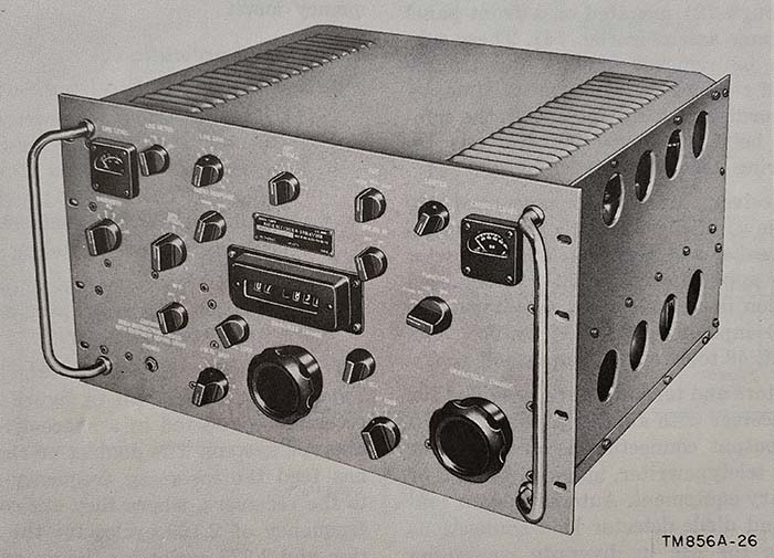
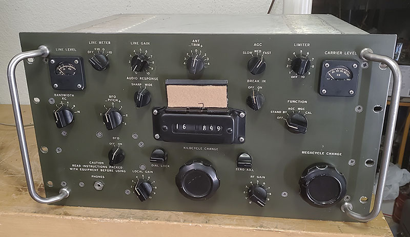
R-390A Capehart contract receivers with Olive Drab panels were
an infrequent product of a repaint by the USMC
but, in this case, I built-up this recreation of the USMC Capehart R-390A, originally in 2010. It has recently (2022)
undergone a complete rebuild for top performance from the "all
Capehart" modules (more details in Part 3.) |
End-user Panel
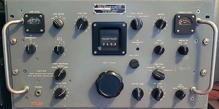
Repaints - The R-390A specifications state that the front
panel is to painted medium gray. The manuals give a specific part number
for the paint but it seems the shade of gray did change over the years
from contractor to contractor. Also, after 60+ years on the planet,
most of the original paint on the panels will have faded somewhat. When choosing the color for repaint, try
to get as close as you can to your receiver's original panel color by
having the original paint matched at an professional automotive paint
supplier. Use the back of the panel for matching since it's probably the
least faded. Only use automotive quality paint for repainting the front
panel. Nearly all R-390A panels are found painted gray, however,
sometimes the end-users did repaint the front panels totally
non-specification colors. Very light gray with black filled nomenclature
panels are fairly common. Admiralty Grey, a light green color used on
the RACAL RA-17 receivers, has been reportedly used on some R-390A
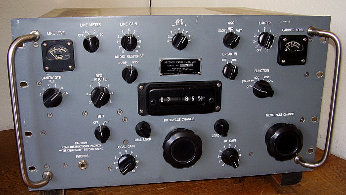
receivers (with black nomenclature.) There were banks of R-390A receivers at
Clark Air Base in the Philippines that had black panels that were actually a
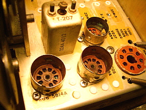
black grained and anodized finish. Once in a while, olive drab panels turn up,
supposedly painted that way by the USMC (see photo above.) At any rate, there's ample
evidence that R-390As were painted colors other than gray when the
end-users had some reason to do so. Remember, all R-390A receivers left
the contractor's facility with gray panels (and that's original) but it
can be considered "acceptable" to paint the R-390A panels colors other
than gray if there is believable evidence that the color was
actually used on a receiver that was operating in a commercial or
military capacity. For example, the black panel R-390As were used at
Clark AB and there is photographic evidence to prove it.
Silk-screened
Panels - All Collins and Motorola R-390A receivers use
front panels that have silk-screened nomenclature. This presents a
problem if the panel is in rough condition. About the only solution is
to look for a decent condition replacement panel. If originality isn't
an issue, a silk-screened panel can be replaced with an engraved panel.
Be aware though, that most Collins and all of the other contractors used a
short serial number tag with the exception of Motorola. The Motorola
contracts used a 3" long tag with different locations for the mounting
holes. If you're trying to maintain originality with a Motorola contract
R-390A, then you're going to have to find another Motorola front panel.
(NOTE: Collins R-390A receivers
built on Order No.14214-PH-51 use the 3" long tag.)
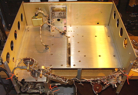
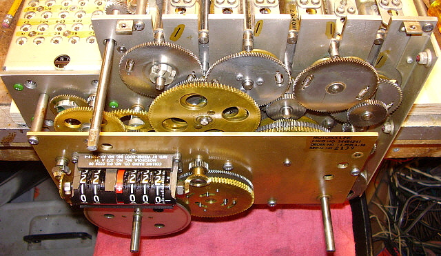
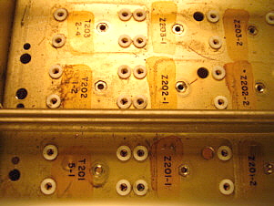
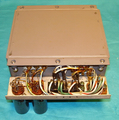
The Back of the
Front Panel - The backside of the front panel has several
clamps for holding the harness in place. Also, there is a printed
circuit board mounted on the back of the front panel just above the
frequency readout bezel. There is a lot of mechanical stress on the
various wires when the front panel is lowered so check all of the wires
to the pots and switches for any breaks or other problems. Since you
have removed the front panel for repainting (or replacement,) then
you'll be remounting all of the pots and switches along with the phone
jack, dial lock and the zero adjuster. Note also that there is a
grounding lug on the upper left (as seen from the front) stud of the
CARRIER LEVEL meter. This provides a chassis connection for one of the
AGC delay capacitors.
Engraved Panels
- Repainting an engraved front panel is very easy. Be sure to mask the
back of the panel (if you're going to paint it) where the panel mounts
to the Main Frame and also a small area by the upper left mounting screw
for the Carrier Level meter. Most panels will have nomenclature on the
backside of the panel that identifies some of the components. Be sure to use automotive grade paint that is
purchased from an automotive paint dealer. This type of paint will have
special hardeners that make the paint really durable. Also, professional-quality
paint will dry "ultra-thin, hard and flat" which will help make filling
the engraving a lot easier. After painting, let the panel dry at least
overnight before doing the engraving fill.
|
Engraving Fill
- I use Artist's Acrylic paint to match the engraving fill paint. If you
use pure white it will look way too bright. You should mix a
color that is close to that found on manila folders - kind of beige
color. Apply the fill paint to only one control nomenclature section at a
time. Use a small paint brush and dab the paint into the engraving.
Don't try to just paint into the engraving - you have to dab the paint
into the engraving to have enough there and, of course, you'll have some
paint around the engraving - that's normal. Let the fill paint set for
about one minute. You'll now have to remove the excess paint around the
area. Use a dampened paper towel folded very flat to remove the excess
remaining paint on the panel. You'll have to be careful not to "pull"
the fill paint out of the engraved area, so keep the paper towel pieces
small and only use them once. You'll have to have several damp paper
towel pieces ready as you do each area on the front panel. Also, I've
found that if you dampen the paper towel pieces using Glass Plus instead
of water the Artist's Acrylic comes off much cleaner. These paper towel
pieces should be just damp - not wet! Generally, you'll have to do each
engraved nomenclature section twice to get a good fill. Let the first
coat dry for about five minutes before applying the second coat. When
finished let the panel dry overnight. The next day you can apply
carnauba wax to protect the panel and the engraving fill which will
enhance the overall panel appearance.
IMPORTANT NOTE:
Don't use Windex to dampen the paper towel pieces. Windex contains
ammonia which might damage the new panel paint. Glass Plus doesn't
contain ammonia but works very well to remove the excess paint without
damaging the panel paint.
Mounting the Front Panel to
the Main Frame - When mounting the front panel, note that
the Dial Lock has to fit over the KC tuning shaft lock-plate. Leave the
Dial Lock loosely mounted so it can be rotated to clear the lock-plate.
Once the front panel is mounted, you can rotate the Dial Lock into
position (the locking grips on each side of the locking plate with the
locating tab in the hole one the backside of the front panel) and
tighten the mounting nut.
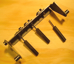
If you have the two large shaft bushings (KC and MC Tuning) and the
three small shaft bushings mounted to the front panel you'll find it
difficult to guide the shafts thru the bushings because of the harness
length. Although you could dismount the harness clamps, it's easier to
just plan ahead and slide the rear panel shaft bushing onto the shafts
and then mount the front panel to the Main Frame. You'll find with the
large openings, it's really easy to guide the front panel over the
shafts with the harness clamps tightly mounted. Once the front panel is
mounted, then slide the rear bushing forward and slide on the washer and
thread on the front bushing.
Once everything is mounted to the front panel and the front panel is
fully mounted to the Main Frame (and tightened,) then you can go ahead
and adjust the panel shaft bushings for the best feel when rotating the
controls.
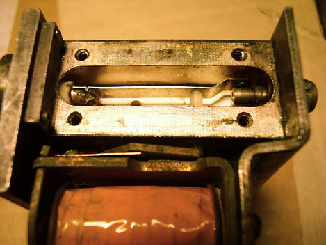
Front Panel Bearing
Adjustment - If you want your R-390A to tune "light and
easy" then you're going to have to adjust the front panel feed-thru
bearings. These are on the KILOCYCLE and MEGACYCLE tuning shafts.
After a thorough cleaning of the RF module gear box, you probably
noticed that the KILOCYCLE tuning was very light and easy to manipulate.
As you reinstalled the slug racks, the tuning became slightly more
difficult to manipulate but was still very light and easy. When the
front panel was installed, all of a sudden the tuning seemed to drag and
was noticeably more difficult to manipulate. This is caused by the two
panel feed-thru bearings. When the RF module is removed and then
reinstalled, it's very slightly, differently oriented and the same goes
for the front panel. Only a slight misalignment of the panel bearings
will cause a "heavy-feel" to the tuning.
Before the front panel is reinstalled, slide the rear bushing onto
each shaft. Fit the front panel into position over the shafts and begin
installing the mounting screws. With all of the screws tightened that
secure the RF module to the Main Frame and all of the screws tightened
that secure the front panel, then slide the rear bushings forward and
mount the washer and front bushing nut. Note how the bearings can be
moved within the feed-thru mounting hole. This is to allow proper
placement of the bushing to act as a guide and bearing for each shaft.
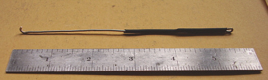
Using a 5/8"open-end wrench to just hold the nut and keep it
from turning, use a tool that has two
tangs that will engage into the slots of
the barrel of the bushing (you can generally use a small "C-clip"
installation tool for this purpose.) Using the tool, gently snug-up
the bushing as it threads into the nut (turn the bushing CCW to tighten.) This method of adjusting the
bushing will prevent the bushing assembly from moving in the over-size
panel hole, which is what happens when only the nut
is tightened. Try the KILOCYCLE tuning. Usually, no matter how well the bearing is
adjusted, there will be a very slight increase in the "drag" because of the
bearing itself. Do the same procedure for the MEGACYCLE tuning although this tuning
is much more difficult anyway since you're moving so many of the
slug-racks and there's also a detent about every turn of the shaft.
Adjust this bearing in the same manner as the KC bearing. You can also apply a drop of
machine oil on the shafts to help lubricate the oil-lite bronze bearing
that is inside each of the feed-thru bearings.
The three small (.25" shaft) bushings are adjusted in the same manner
(ANT TRIM, BANDWIDTH, BFO.) Use the Correct Lock Washers
- Each nut that secures a potentiometer or switch should have a internal
tooth lock washer installed. There are five 6-32 flat head phillips
screws that mount into the Main Frame bed and into one of the vertical
dividers (into pem-nuts) on the underside of the bed. These screws each
have a #6 conical external tooth lock washer installed. If you're
missing the conical lock washers, they are available from McMaster-Carr
(boxes of 100 - they're cheap.) Notice that the three 6-32 flat head
phillips head screws that mount the cable clamps have split ring washers
mounted on the back side of the clamps (along with nuts.) The eight
8-32 flat-head screws that mount the panel to the main frame vertically
will thread into Nylock pem-nuts, so no lock washers are required. |