|
Purpose of the
R-725 Modifications - For Adcock Direction Finders - or - Was that just
a Cover Story? - The usual purpose that is given for the
R-725 mods was for compatibility with military portable direction
finders that used four vertical antennae per installation along with
three receivers. The DF system used went back to the Bellini-Tosi type
of DF set-up that used two crossed loop antennae with a rotating loop
inside to create a radio-goniometer. Bellini and Tosi had discovered
that crossed loop antennae would "re-radiate" the signal they were
receiving within the small field inside the antenna's space. The
"re-radiated" signal retained all of the directional properties of the
original signal and could be measured for varying signal intensity
dependent on direction. The crossed loop antenna size didn't affect its
frequency of operation allowing for reduction in the size of DF loops on LW. Of course, the original Bellini-Tosi system dated from around 1900
and the system was sold to the Marconi Company around 1907. By the early
twenties, vacuum tube amplifiers were being added to increase
performance capabilities of the DF antennae systems. The most common B-T
DF systems used the crossed loops. The Adcock system was developed during WWI and
consisted of four vertical antennas ground-mounted and arranged in a
square shape. The connections from the four square
verticals were shielded or ran underground so the system didn't respond to skywave propagation and
allowed ground wave DFing over long distances. Some Adcock four-square
vertical antennas were connected to a Signal Goniometer that was
motor-driven at a relatively slow speed (~27RPS) and the output went to
the DF receiver. There was also an Indicator Goniometer that rotated
along with the Signal Goniometer and the Indicator Goniometer was
connected to a visual azimuth indicator (like an oscilloscope.) The
output of the DF receiver went to the azimuth indicator circuitry that
down-converted the signal to 72kc and that was also routed to the
Indicator Goniometer. The azimuth displays
provided instant visual direction indications. After WWII, larger DF systems continued to be
developed up to the mammoth "elephant cage" antennae ("Wullenweber"
was the common name but the actual name is Circularly Disposed Antenna
Array or CDAA) that were almost one thousand feet in diameter and
consisted of two concentric "rings" of multiple vertical antennae
(between usually 120 verticals in the outer, 9mc-30mc ring and 40
verticals in the inner 2mc to 9mc ring.) Wullenweber CDAAs were multi-purpose
and could provide several functions simultaneously with several
different monitoring stations, DF stations, recording stations, all working together
simultaneously
to provide
accurate signal analysis within wide frequency spans. By the
1990s, most of these large arrays were becoming obsolete and nowadays
all Wullenwebers have been dismantled and removed from their original
sites.
The mechanical filters used in the R-390A sometimes resulted in
signal path phase shifts that caused errors to show up in the DFing
electronics. When used with the portable four square Adcock antennas, the low frequency
modulation added via the Indicator Goniometer interacted with the
mechanical filters creating the error. Early versions of this portable DF set-up
had used R-390 receivers and the Indicator Gonimeter interaction didn't
occur. In the late-1950s, the USAF
wanted to further reduce the size of the entire DF system so it could
easily be towed
around on a trailered hut. This system was originally designed and
tested to use R-390 receivers and there was no interaction at that time.
But, as this mobile system evolved and newer version started to be
produced, the
R-390A receiver was tested and the interaction became an issue. The
R-390 had been out of production for several years, so the solution was
to design the new portable system to use modified R-390A receivers that
could be easily purchased. Arvin Industries was the main contractor with
Servo also doing some rework. The modified receivers would have the
Series 500 IF module, essentially a R-390 IF module that was slightly
updated to not require any rework to the R-390A receiver it was
installed into. That eliminated the mechanical filter phase shift
problem. Additionally, a 60hz hum appeared on the
PTO tube filament and there was also a 60hz hum produced by the PTO
heater. These also interfered with the LF modulation of
the DF system. A special "hum bucker" chassis was added to the receiver
that essentially operated the VFO tube, the BFO tube and the 3TF7
Ballast tube on +25vdc. Also, a grounded ferrous metal shield was added
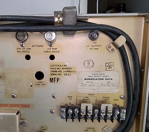
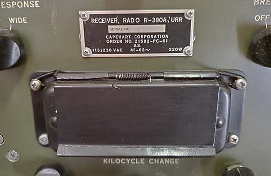
to the PTO housing to prevent hum from the PTO heater being an issue. Arvin bought
brand new R-390A
receivers in 1967 from Electronic Assistance Corporation and the
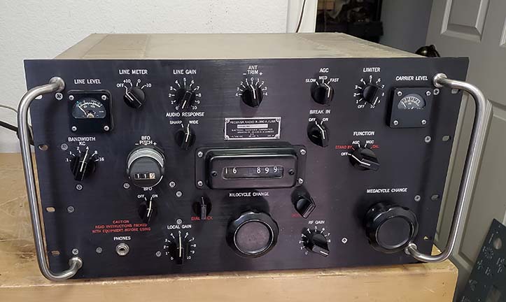
modifications were installed and, when complete, the receiver was tagged
as "R-725/URR." The tags will generally show Arvin Industries as the
contractor but sometimes Servo will be encountered. The quantity of
R-725/URR receivers needed by the USAF was fairly small (less than 300,
according to Moe) and thus today the R-725 is seldom encountered.
Contract number on the R-725/URR was DAAB05-67-C-2338.
All of this mechanical filter phase shifting interaction
with the Indicator Goniometer seems a little exaggerated and perhaps it
was hyperbole to obfuscate that actual need for the R-725. So, was there another purpose that was the "real"
reason that the R-725 was created? According to an article that appeared
in Electric Radio in January 2006 by Chuck Teeters (sent as an e-mail to
me by Les Locklear,) there was a "top
secret" purpose for the R-725 and the receiver "mods" were initially
created for that "secret" project. The R-725 was a product resulting
from the Cold War jamming that was common between the USA and the USSR.
In the mid-to-late 1960s, there was a new system that was being
developed called "Tropicom" that was an upgrade to the antennas and
transmitters to improve HF communications for the military. The upgrades
also included the incorporation of the "F9c" anti-jamming/crypto system.
The F9c system used a spread spectrum transmission of digital noise and
signal that ran through a digital encrypo-key generator that had 144
stages of looped-feedback that also fed through phase modulators to
maintain proper phase relationships of the signal and noise. When used
with a R-390A on the receive end, the phase changes in the mechanical
filters interfered with the recombination process and the system didn't
work. When used with R-390s with a standard IF amplifier circuit, the
F9c system worked fine. Since the R-390 dated from the early-1950s,
there was only a limited supply of those receivers still available and
those that were available needed constant maintenance. The ultimate
solution was to have new R-390A receivers built with new-build R-390 IF
modules installed.
In order to keep the F9c project "secret," the actual
use of the R-725 couldn't be known to those outside the project. Since
there really was the mobile Adcock DF system upgrades that could
probably use a
non-mechanical filter type R-390A, the R-725 was directed to be built
for the DF purpose only and the goniometer interference story circulated
to obfuscate the actual need for the R-725. Those running the F9c project had the
R-725 order quantity doubled and half of the R-725 receivers were
procured for F9c use while the other half went to the portable DF systems. The
secret classification stayed on with the F9c system and it was used for
quite a long period with many upgrades over the years. So, even though
half of the R-725 receivers were used in direction finders, the other half
had a "secret life" used in the anti-jamming/crypto communications world
of the NSA, USAF and the Signal Corps.
UPDATE 2026: Interesting Notes from
Les Locklear: I received an e-mail from Les Locklear that
reported on a few of the R-725 receivers that Les had inspected and
taken notes on. He scanned and sent the notes along in an
e-mail. Two receivers were EAC conversions with EAC data plates but one of the R-725s was a
1955 Collins R-390A that still retained its Collins data plate. This
Collins R-725 might have just been a front panel transplant because the
rear panel of that receiver was the expected EAC type. From Les' notes it appears
that he could only inspect the receivers externally. There were also
serial numbers on the data plates that didn't seem to relate to the
Series 500 serial numbers. Les' examples were as follows,...R-725 #1 had a serial number of AO902
with the "AO" much larger than the "902"
(presumably an EAC data plate.) R-725 #2 was the '55
Collins front panel with SN of 848 but the Main Frame's rear panel was
'67 EAC. R-725 #3 had an EAC data plate serial number of 3074. This
information seems to put into question the practice of using the serial
number of the Series 500 IF module as the R-725 serial number. BUT, that
practice must have only applied to those R-725 receivers that were in the initial batch
of 300 receivers from Arvin Industries that used "Arvin" data plates.
These three R-725 receivers that Les inspected didn't have Arvin
Industries data plates. However, Les did have another R-725 that did
have the Arvin tag with the serial number 95, that does indicate that Arvin Industries R-725 used
the same Series 500 IF module serial number as the receiver serial
number (as indicated by Moe Sellali.) An additional interesting note is that the two EAC R-725 receivers that Les inspected had frequency readout dial
covers that had been painted yellow for some reason (Les thinks that the black paint may
have been removed and the zinc-chromate primer accounted for the yellow
color.) What I infer from
this information is that the initial 300
R-725 receivers came from Arvin Industries and these initial receivers
are as described in this write-up. These Arvin receivers have the same
serial number on the Series 500 IF module as on the receiver's data
plate. Later, as other R-725
receivers were needed, someone else did the conversions. These
conversions generally used EAC receivers but not always. Series 500 IF modules (or
modified R-390 IF modules) were installed in these later receivers but other combinations of parts
might show up since the conversions were probably performed by military
depots and used what parts were easily available. Whether these later
conversions used just the Series 500 IF module (or a modified R-390 IF
module) alone and didn't include
the PTO modifications and hum bucker isn't known. Thanks to Les for the
detailed info.
Testing the
R-390A with a Series 500 IF Module - With the donation of
the Arvin R-725 data plate it looked like I had all of the parts to
build-up a R-725 if I could supply a complete 1967 EAC R-390A. According
to Moe, when Arvin built-up the R-725 receivers they purchased new '67
EAC R-390As direct from EAC to fulfill the contract, thus all Arvin
R-725s are converted '67 EAC R-390A receivers. I decided to use my '67
EAC SN: 974 R-390A because this receiver had recently been partially
"cannibalized" to complete another EAC R-390A. I needed to replace a
defective RF transformer on the 2-4mc antenna stage and do some minor
alignments. Luckily, the "junk" R-725 RF deck supplied a good RF
transformer. The first step was to check out and test the Series 500 IF
module. One of the IF transformer cans was severely dented and needed
"body work" to correct. All of the tubes were missing. I checked over
the underneath and all components appeared to be in good shape. I gave
the Band Width switch a DeOxit treatment. I needed tubes and tube
shields. I found all of the tubes in my tube storage. The shields were
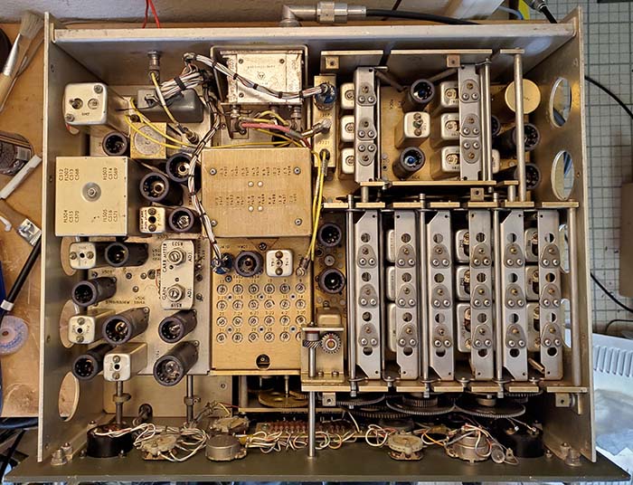
"borrowed" from the EAC IF deck as was the 3TF7. The Series 500 is a
"tight fit" but it does fit (see above photo.) The chassis is somewhat
longer so the captive screws are located on the chassis rather than on
the flange. The Band Width and BFO shafts are shorter than on the
standard IF deck. The input and output coax connectors are in a
different location but the cables reach easily. There is no clearance
for the rear IF output cable as it is directly behind one of the 12AU7
tubes. The junk R-725 main frame even had the rear IF output connector
totally removed. A special connector is required for the IF output on
the R-725 conversion. The Amphenol connector has to be turned 90 degrees
but everything lines up and there is ample flexibility to allow for this
connection.
With power applied, everything came up as expected. The
first thing noticed was that the IF Gain must have been at "maximum" -
it was. After some testing and listening, I reduced the IF gain by about
50 percent. This provided ample IF gain and much lower noise levels.
Carrier Level was adjusted on 15mc to zero with the antenna
disconnected. BFO was zeroed. I didn't do a 455kc IF alignment since
this was just a "check out" but the IF deck already seemed to be
performing better than expected.
|
Installing the "Hum Bucker" - Thanks to Craig
W6DRZ, I had a C-D with data on all of the R-390A variants,
including the R-725. The R-725 manual was on the C-D and had step-by-step
instructions for the installation of the "hum bucking" chassis
plus a schematic that showed what was accomplished after the
chassis was "wired" into the circuit. The "hum bucker" consists
of a small 25vac transformer, a resistor divider network that's
connected to B+, a connector and chassis. Essentially, the "hum
bucker" modification first isolates the filaments of the VFO
tube, the BFO tube and the 3TF7 ballast tube and connects these
components in series to the the 25vac winding of the small
transformer. This winding is NOT connected to chassis but is
"floating." The 25vac also has a resistor network that has a
220K resistor from B+ to one side of the 25vac winding and a 33K
resistor from that junction to chassis. This divider results in
about +25vdc "riding on" the "floating" 25vac tube filaments
which results in the DC "swamping" any 60hz hum on the VFO and
BFO tube filaments. If pin 3 of the VFO tube is measured
referenced to chassis it should be +25vdc.
To integrate the "hum bucker" into the circuit
requires wiring a harness of six wires from P-119 on the "hum
bucker" into various parts of the R-390A. Of these six wires,
two are routed to the Power Supply module connector (AC in,) one
is routed to the IF module connector (Hum Bucker Filament
voltage to VFO, BFO, 3TF7 with original R-390A wire
disconnected) one is routed to the AF module connector (B+,) one
is routed to the PTO connector (VFO tube filament series string
return) and one is connected to the main frame chassis. Luckily,
the actual R-725 junk main frame that I had still had the "hum
bucking" wiring intact although this six-wire cable was cut to
remove the "hum bucking" chassis in the past. Again, luckily, I
had the exact same "hum bucking" chassis, so I had the other end
of the wiring harness with the proper connector. The six wires
are laced and some wires are routed though plastic sleeving. I
wasn't able to find any stranded 20 gauge wire that was even
close to the original wire used so I decided to restore the
original harness. I removed the remaining side of the original
harness from the junk R-725 main frame. I made a drawing of how
the wire routing was originally done. Luckily, where the harness
was cut actually ends up down next to the PTO so the repair
isn't visible. By carefully splicing the six wires together the
overall length of the harness was only shortened by about a half
an inch. The finished repair was covered by black shrink tubing
to make the repair look sort of authentic.
Each of the six wires were routed next to the
main front-to-rear harness next to the PTO. The six-wire harness
is tied to the main harness with waxed lacing string in six
places. Each wire has to be then routed to the specific module
connector to make the proper connections. The Amphenol
connectors have to have their covers pulled back to access the
connector pins. Most of the connections parallel the wires
already soldered. There is ample space to loop the new wire
connection thru the terminal and solder it. The original
sleeving is then returned over the terminal when the soldering
is complete on each connector. The Filament connection to the IF
module connector has to have the original wire disconnected and
then taped (or insulated.) Then the new wire from the "hum
bucker" is soldered in its place. The PTO connector has to be
accessed to add the filament connection to pin C to complete
filament routing. This completes the addition of the "hum
bucker" to the circuit. |
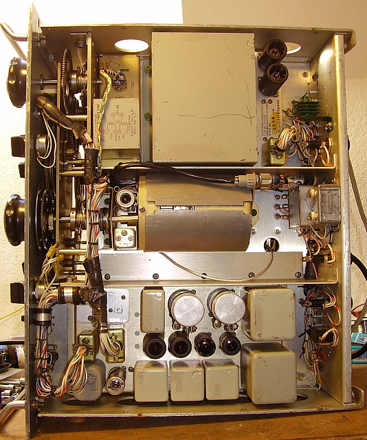
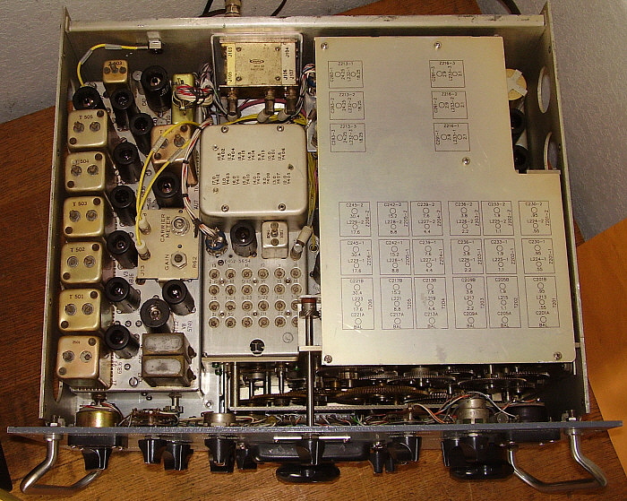
photo above: The
underside of the R-725 showing how the "hum bucker" chassis is
mounted in front of the power supply. The hum bucker harness is
routed thru the receiver harness to the various module power
plugs for connections. Also note the ferrous metal shield over
the PTO. 2018 photo |
Mounting the
Hum Bucker Chassis - Mechanically, the "hum bucker" is
mounted in front of the R-390A power supply. This requires a bracket
with pem-nut on the PTO side plate and two holes on the outer side panel
to mount the "hum bucker" chassis. I removed the PTO side plate from the
"junker" R-725 main frame because it had the original bracket already
mounted. I removed the original PTO side plate from the R-390A and
installed the R-725 side plate in its place. I carefully measured the
original "junker" R-725 main frame side panel for the correct location
of the two mounting holes. I then marked and drilled the R-390A side
panel in the original manner. These modifications allowed the "hum
bucker" chassis to mount exactly as it did in the original R-725. Now
the "hum bucker" installation was electronically and mechanically
complete. On to the PTO next.
Testing and
Calibration the PTO - I'm using the original Cosmos PTO
from the junk R-725 main frame. This PTO already had the mod installed
that lifted pin 3 of the VFO tube from chassis. Then a wire was
connected to pin 3 and it was routed back to the PTO connector where it
is connected to the unused pin C. Also, a .01uf ceramic disk was
installed from tube socket pin 3 to chassis. The PTOs that were used in
the R-725 had a ferrous metal shield installed over the can of the PTO
and this PTO did have that shield installed (eliminates any radiated hum
if the 24vac PTO heater is operated. Since it's 60~ AC, the shield has
to be ferrous metal.) I have a R-390 PTO test
fixture that was given to me by W6MIT. The test fixture allows powering
the PTO and employs a digital turns-counting dial to accurately set the
end-point error to <0.5kc. I had to supply +195vdc B+, Regulated
+150vdc, 6.3vac and chassis ground. Output was measured from the coaxial
cable of the PTO using a digital frequency counter. I used a Lambda 25
for the B+ and 6.3vac and a regulated +150vdc supply. With the PTO on
the fixture and powered up, the first step was to adjust the PTO output
to 2455kc, then set the counter to 00.0 and tighten the coupler. The
fixture counter works the opposite to how the PTO functions in the
receiver. Since it's a mechanical readout on the drive rotation it
doesn't really matter and our actual check was to verify that the PTO
output changes from 2455kc to 3455kc in exactly ten turns. A quick check
revealed that the end-point error was close to 1.0kc. I ran thru each
turn to check linearity and this PTO was "right on." If it had been
necessary to adjust the PTO end-point I would have followed the
procedure as detailed in the PTO section further up this web page. To
install the PTO only requires that it be set to 3455kc output with the
R-390A having xx.000 on Veeder-Root counter. When the R-390A Veeder-Root
counter is set to xx.000 then the Oldham coupler aligns correctly. The
power connector is installed and the output coax connected to the RF
module. This completed the PTO modifications and, in fact, completed all
of the R-725 mods necessary.
|
Installing the
Special Right-angle Coax to BNC fitting for IF Output -
If it's attempted to fit the original IF output coax cable onto the
original coax box BNC Jr to BNC output fitting, it will become obvious
that there isn't enough clearance due to the 12AU7 tube directly in
front of the connector. For the R-725, Arvin replaced the rear panel BNC
Jr to BNC connector with a special mini coax input at a right angle to
BNC output connector. This "low profile" fitting provided enough
clearance to then connect the exiting cable to J-14 which is the IF
Output on the Series 500 IF module.
To install the right-angle fitting requires a slight
enlarging of the mounting hole which Arvin apparently did by filing the
hole until the connector fit (I did check the junk main frame and it
showed evidence of filing.) The coaxial cable should be installed onto
the connector first. The center conductor of the coax is routed through
the right-angle tube and the shield is placed over the outside of the
tube. The center conductor is soldered to the center pin making sure the
teflon spacer is installed afterward. Then the crimping barrel is placed
over the shield and right-angle tube and crimped in place. Then the back
cover nut is installed. The BNC right-angle fitting with coax attached
can then be mounted to the rear panel of the receiver with a locking
washer and nut. Then the BNC Jr. end connector can be attached to J-14.
This completes the installation. Thanks to Moe CN8HD/W9 for supplying
the correct coaxial right-angle fitting (as mentioned, my coaxial
fitting was missing from my "junk" R-725 main frame.)
Testing the
R-725 - The R-725 mods were for a DF set-up (or for
Tropicom) so the
changes to the PTO tube, BFO tube and 3TF7 tube filament supply are very
subtle and not noticeable by just listening. However, the "big change,"
that is, adding the Series 500 IF module and thus eliminating the
mechanical filters and adding more IF stages,...that is very noticeable.
In fact, it's impressive! The gain is amazing. I have the Series 500 IF
gain set to 50% and the strong signals will still send the Carrier Level
meter to +80 or +90 db. If I tune off of the signal, the meter drops to
+10db. The selectivity is still very good. Just about as good as
mechanical filters. The R-725 has become my standard "vintage military
radio receiver" and it's set-up out in the shop with the T-368
transmitter and using a Collinear Array
antenna. The R-725 can always be counted on the "pull in" the
weak signals and
is easily able to cope with any QRM. Audio quality is good and sounds
pretty close to a typical R-390 receiver. Probably one could sum up the
R-725 as an "easier to work on R-390" with all of the benefits of the
R390 without as many headaches. See 2026 Update below.
Wrap-up
- A Restoration or a Recreation? - I was extremely
careful to use authentic R-725 parts harvested from a "destroyed,
incomplete" R-725. I used SN:74 Series 500 IF module, the original
ferrous metal covered PTO, the original Hum Bucker power supply and I was very careful to exactly duplicate how the
Hum Bucker wiring harness was integrated into the R-390A harness. I even used the
original Hum Bucker harness for authenticity. Original R-725 sheet metal
was used where needed. The receiver used for the conversion was a
1967 EAC R-390A, like the original SN:74 had been before it was
virtually destroyed with an ax. The data plate used was an exact copy, etched tag -
not a silk screened tag but one made just like the originals. Even the
serial number stamped in the tag matches the serial number ink stamped
(in 1967) on the back of the Series 500 IF module. And, all of the R-725
parts came from the same "destroyed, incomplete" R-725 which must have
been the original SN:74. So,...when looking over this recreated R-725/URR,...I
consider it to be an authentic restoration of SN:74. It's just
that the original 1967 EAC R-390A that Arvin modified in 1967 has been
replaced with an identical 1967 EAC R-390A and my authentic modifications
and restorations were performed in
2018. Close enough,...right?
UPDATE 2026: For the past eight years, the
Arvin R-725 has been operating with the Barker-Williamson
contract T-368 transmitter. The antenna is a 130' Center-fed
Inv-Vee fed with 44' of open line (the Collinear Array had to
be
rerouted to the house upstairs station due to storm damage.) The matching device
is a Johnson KW Matchbox. The potent 350 watts output from the T-368
transmitter matches the incredible abilities of the R-725. The
sensitivity is just about the best of any R-390A version and the
advantage of having the R-390 IF deck is responsible for the
tremendous gain the receiver has. The R-725 is installed into a
CV-979A cabinet that was given to me about 10 years ago. "Given"
because it looked like something (or someone) really, really
heavy sat on top of the cabinet and bent the top. I had to do quite a bit of body work to get it
straight again and that forced me to do a repaint. Fortunately,
it all matched fine and ended up looking great. The CV-979A is a Taffet Electronics
(luckily, the silk-screened ID was inside the cabinet) version from the mid-1960s |
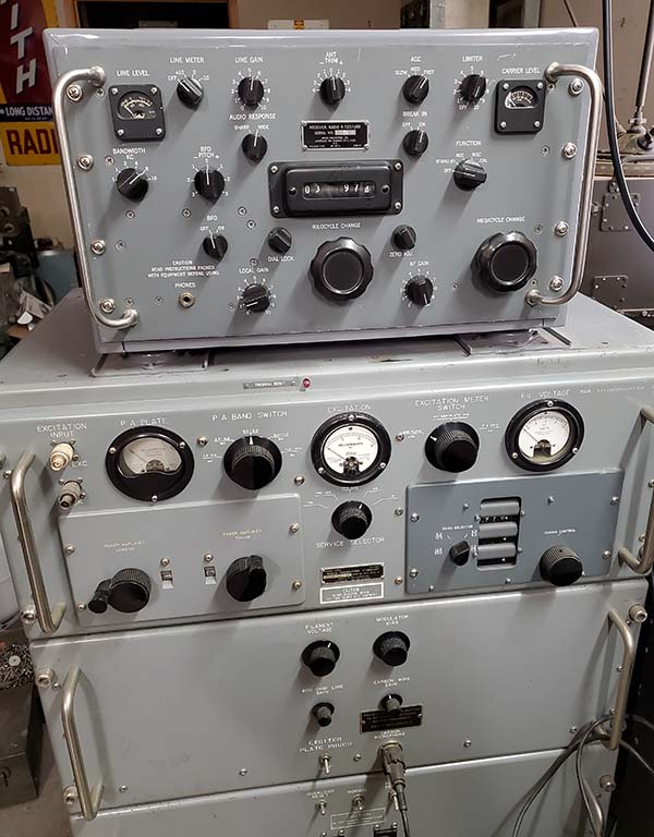
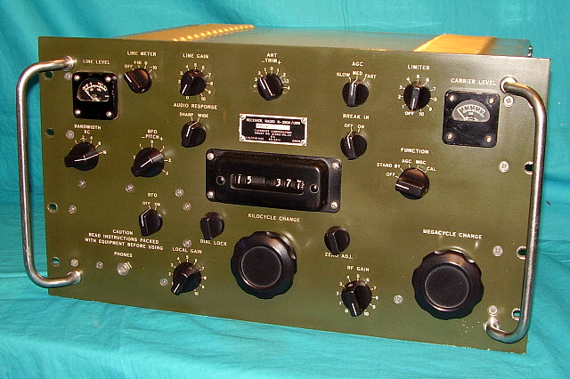
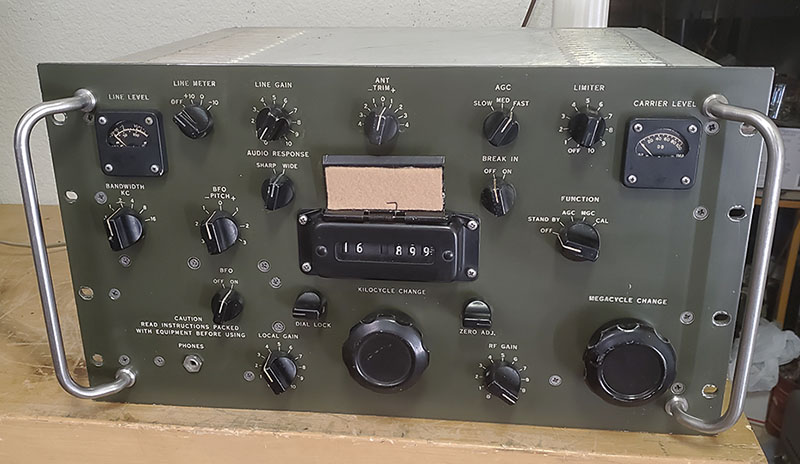
T-368/URT Transmitter and R-725/URR
Receiver 2026 photo
If you want to read about
the restoration of this 1952 Barker & Williamson T-368/URT
"Basic" Serial Number 29, Order No. 3472-PHILA-52, there's a
complete write-up on this website. Use the Home Page for
navigation. |
|