| The Equipment - All electrical and electronic
equipment in the D.F. hut had to operate on DC provided by a storage batteries.
A six volt vibrator type power supply was used for the R106. Although it can't be
seen in the drawing because its likely location was in the corner near
the R.107 operator position, there must have been a set of dual six volt
storage batteries
connected in series to supply the R.107 with its 12vdc power
requirement. Three types of loop antennas were used and two of loop antennas and the
vertical "Sense" antenna were carried in disassembled form
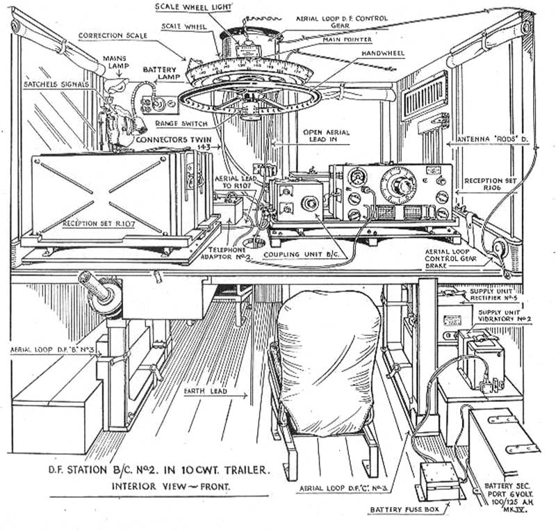
inside the hut. The loop antenna in use was rotated with a
Handwheel
that was located above and mounted to the
ceiling of the hut. Above the handwheel was the loop azimuth compass,
called "Scale Wheel"
that, when set up accurately, would measure the bearing (direction in
degrees from magnetic north) of the signal being received. There was a
Range Switch at the bottom of the handwheel
that possibly was a impedance matching network that was switched to
match the particular loop being used (three different loops could be
installed.) Two receivers were set
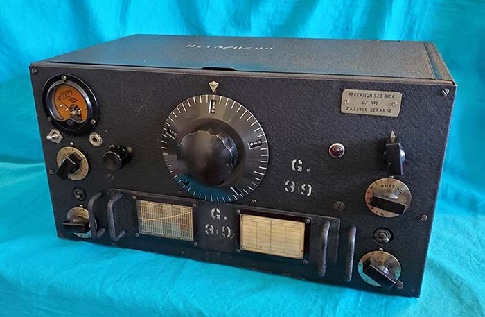
up in the hut, the National Company, Inc. Reception Set R106,
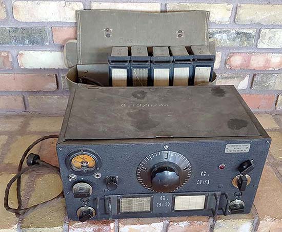
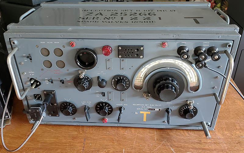
a HRO-M receiver, and the British Army
Reception Set R.107 built by
Radio Transmission Equipment Ltd. or by Ferguson Radio Company (there
may have been other contractors that built these sets.) In the
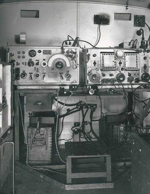
drawing above, the R.107 is shown from the rear. Note in the drawing
that both receivers are "strapped" to their respective mounts by leather
belts to prevent movement while the trailer is being towed along bumpy
dirt roads or in fields with no roads. Both receiver mounts were slightly elevated at the front for
a better operator's view of each receiver panel. The loop antennas were diamond
shaped with a vertical antenna (built up from four "rods") to act as the "Sense" antenna.
Two antenna leads were routed to the Coupling Unit B/C.
with one lead coming from the Loop and the other lead was from the Sense
antenna. The Coupling Unit B/C would have the circuitry to combine the
signals from the Loop and Sense antennas into one output that was
connected to the Antenna input of the D.F. receiver. There's another antenna lead shown as "Open
Aerial Lead In" and the assumption would be that it was an
auxiliary antenna not associated with the D.F. Loop and Sense antennas
but still connected to the Coupling Unit B/C. The "Open Aerial" was
probably connected to the receiver that wasn't being used for the D.F.
operation so that receiver could then operate in an "enemy signals
search" (intercept mode) or for receiving communications
from D.F. Headquarters. The Coupling Unit B/C
had switches on its front panel that could have allowed the operator to select
the routing of the antennas to the two receivers and to also select
the Loop and Sense antennas' configuration. The operator would have needed to be
able to select just the Sense Antenna
for an omni-directional pattern
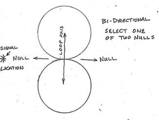
used when searching for signals. Then
just the loop could be selected for a bi-directional pattern
(a "figure-8" pattern) to find the
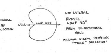
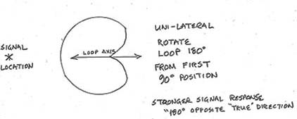
general direction of the signal. Finally, the combination of the Loop
antenna and the Sense antenna, sometimes called
Uni-lateral Direction or
True Direction, could be selected to create a
cardioid pattern to determine
True Direction. True Direction required that the radio operator tune in
the desired signal but the ultimate indication of direction was to
rotate the loop antenna for the minimum signal from the receiver, called
"the null." The loop compass would then indicate the direction in
degrees from magnetic north (provided the hut and loop plus the loop
compass had been physically aligned correctly.) The operator would have to know the correct Magnetic
Variance (also called Magnetic Declination) for the area to allow
calculating "True Direction." Magnetic Variance is different
in areas all over
the Earth so it was normally shown for the area on special charts used
for direction finding. The Coupling Unit B/C. could be switched to
either receiver and allow one receiver to become the direction finding
receiver. Additionally, most D.F. systems had some way to "balance" the
antenna response differences of the Loop compared to the Sense antenna.
The Coupling Unit B/C might have had a gain control (generally on the
Sense antenna) that allowed the operator to equalize the two antenna
responses (usually to a test signal.) It was also possible during the
set-up of the D.F. station hut to orient its position and adjustment of
the loop and loop compass to compensate for the magnetic variance of the area and
have the D.F. compass read "True Direction" without the need for the
additional calculation. Since magnetic variance could be either easterly
or westerly, the operator had to know whether to subtract or add the
magnetic variance from or to his "Magnetic Direction" bearings. To eliminate
this possible source of error, sometimes the loop-compass was set up to
read "True Direction." In most cases, bearings were "radio
transmitted" to a communications D.F. center (usually not far away) that
performed the transfer of the radio direction bearings to maps that could then triangulate
the location of the enemy transmitter. This type of D.F.
is called "Aural Null" and implies that the operator was listening
to the receiver output for the signal-loop null using headphones and
that was certainly the primary method used for discerning the
signal-loop null. Sometimes indicating meters were used for
a more accurate null measurement. The R106 S-meter
could be used for a D.F. indicator (the null.) This would have required
the AVC to be used and would only provide carrier level indications in
the AM-Voice mode. The R.107 didn't have a
Carrier Level meter so, if an external indicator would have been needed,
it might have been possible to use an audio output meter to indicate the null but it
would have depended on the
type of signal. The modulated carrier output of an AM-Voice signal would
have the audio meter needle "bouncing" following the modulation and that
would make finding a minimum null difficult. The same problem would
happen when CW was received since the signal plus BFO would result in
the same "bouncing" audio meter indication. Only a constant carrier
signal would have provided a stable audio signal that would allow
finding the null via an audio meter indication. This type of signal would only
occur during "tune up" or during pauses in voice modulation. It's possible that the
Telephone Adaptor No.2 was
provided with external sensitive audio response meters that had
damped-response circuitry to act as D.F.
indicators (this device is mostly hidden by the R.107 in the drawing.) It might be possible that the Telephone Adaptor No.2 could
have provided some type of usable null indicator since the typical Audio Output Meter
really wouldn't have worked. Note that
the Reception Set R106 has a cord running from the receiver's headphone
output jack to the Telephone Adaptor No.2. In the HRO circuit, the
headphone jack is capacitor-coupled from the first audio amplifier plate
so the audio signal isn't particularly "high level." However,
for rapid D.F. bearing measurement a meter indication wasn't actually necessary. Since the
loop-null is very
sharp (very narrow) it can easily be discerned quite accurately by
just listening.
|
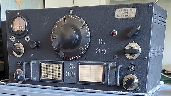
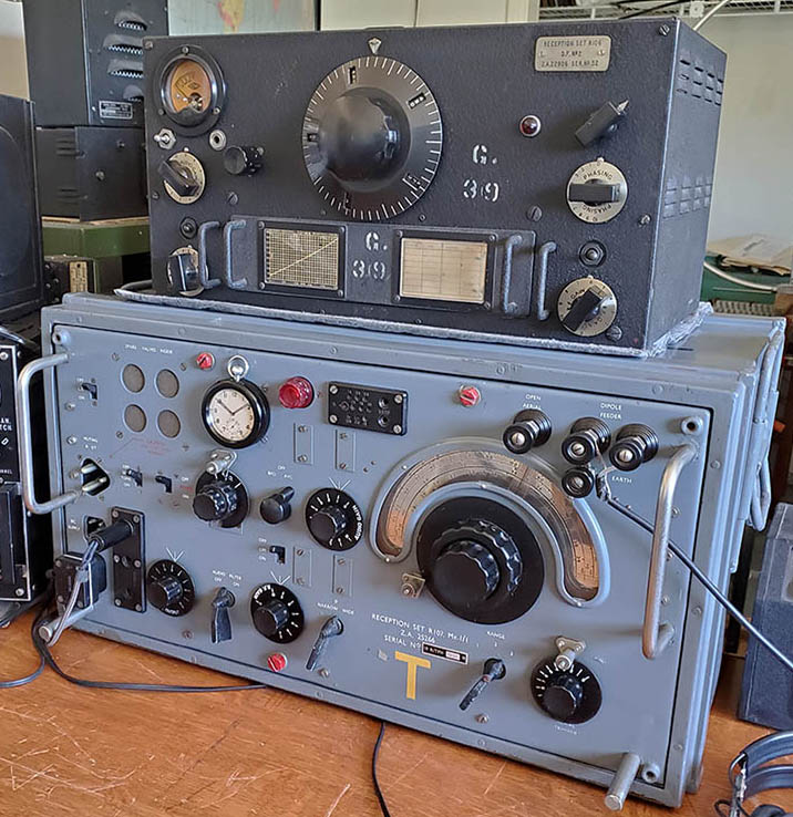
Reception Set R106
|
|
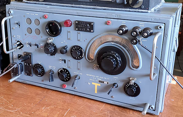
Reception Set R.107 |
When transporting the hut to the field location, the two Loop antennas
were stowed inside the hut.
Aerial Loop D.F. "B"
No. 3 and Aerial Loop D.F. "C" No. 3.
were installed in compartments by the wheel wells of the trailer.
The implication of the drawing is that
Aerial Loop D.F. "A" No. 3 is installed on the roof
of the hut since it's not shown. That would be a total of three Loop antennas
available depending on the frequency range of interest. The "Sense Antenna" was a
vertical antenna comprised of the four rods shown as "Antenna Rods D"
that mounted to the wall of the hut.
If the drawing is studied carefully, it can be seen that there's a chair
bolted to the floor behind the Telephone Adaptor No.2. This second chair provides for two radio operators to
be in the hut simultaneously. Since all of the connections for the R.107 are on the
front panel, it's obvious that the drawing shows the R.107 from the rear.
This also implies that what looks like a window on the rear wall is
actually another access door. Without a door on both the front and back
how would each operator get to their respective positions? The drawing
indicates that it's showing the
D.F. hut from the "FRONT" but that designation might be dependent
on which operator you were talking to.
The ability to change loops would allow a greater frequency coverage
for the entire B/C No.2 station although its specified use was D.F. for 480kc up to
10mc. However, the R.107 tuning range didn't go below 1.2mc therefore
the R106 had to be used for frequencies below 1.2mc. This would have
necessitated having HRO coil set E and HRO coil set F to allow frequency
coverage of 480kc to 900kc on coil set F and 900kc to 2.0mc on coil set
E. Between the two receivers, the specified frequency coverage of 480kc
to 10mc would be easily accomplished. Actually, if all of the R106 coil
sets were available, coil sets JD (1.8mc to 4.0mc,) JC (4.0mc to 7.3mc)
and JB (7.0mc to 14.4mc) would allow tuning to be extended up to 14mc.
Coil set JA tuned 14mc to 30mc, although that wasn't in the D.F. Station
B/C No.2 frequency
coverage specifications. It's possible that while one receiver was
operating in the D.F. mode the second receiver was tuned to receive
orders or deployment details from the military command and that's why
there's a separate antenna and an extended frequency coverage on the
R106. However, it's also quite likely that one receiver was used for
D.F. while the other receiver was used for enemy signal intercept. Use
of the second receiver may have been variable depending on the
installation and the task that had to be performed. From the drawing
that implies the view is from the "Front" of the hut and the fact that
the "Aerial Loop Control Gear Brake"
is adjacent to the operating position of the R106, it appears that the
R106 was the primary D.F. receiver and the R.107 was for intercept or
for receiving communications. No transmitting
capability is shown in the drawing. If the towing
vehicle had radio T/R capabilities, then any two-way communications with D.F.
Headquarters could have used that set up.
In the upper left rear part of the hut are two lamps. One is shown as
"Battery Lamp" and the other is
shown as "Mains Lamp." The
implication is that the D.F. hut ran on DC voltage when deployed in the field
but
it was possible to use the "AC Mains" as a power source if it
was available. However, it looks like the radio equipment was normally
set up for DC operation only. To switch the R.107 to AC operation would
require pulling the chassis from its cabinet to move the power supply
switch from "DC" to "AC." To convert the R106 to AC would require
operating the R106 from a different power supply. Possibly the Supply
Unit Rectifier was the AC operated power supply for the R106 and the
Power Unit Vibratory No.2 was the DC operated power supply (more
details on R106 power options are in the R106 section description
further down this write-up.) It would seem that the AC Mains
operation might be for convenience when troubleshooting or changing set
ups at a depot and then DC operation was normal for power in the field.
The length of operational time, of course, would depend on the current
draw from the storage batteries. No charging system is shown but it
certainly had to be possible to charge the batteries, or even operate
the D.F. hut using an external motor-driven DC generator. It might have
also been possible to power the hut in the field using some sort of
motor-driven AC alternator-generator. It's interesting that the storage
battery is shown as "Battery Sec. Port. Six
Volt 100/125AH" with the emphasis on "Sec Port" implying a
"secondary" and "portable" use for the battery, even though it's shown
as the power source for the Reception Set R-106 when operated with the
Power Unit Vibratory No.2. However, since that six volt storage
battery is the "secondary"
where's the "primary" battery? It could be out-of-view in the
drawing and located in the corner near the R.107. It would have to
supply 12 volts and probably consisted of two six volt storage batteries
connected in series.
Another piece of equipment not shown is a radio transmitter for
communication of bearings for triangulation information or other
observations to the D.F. Headquarters. Usually, these were small battery
operated "handie-talkie" types of transceivers if the distance involved
wasn't very far. It could be that the towing vehicle would have had
T/R communications equipment installed for that purpose and the range of
that type of communications equipment would be far greater than the "handie-talkie"
type. It's certainly possible that other items like
maps, set-up compasses, parts, tools and other necessities might have
been in the vehicle that towed the D.F. Station B/C. No. 2 to its
operating location. There were several other pieces of auxiliary
equipment such as satchels signals, various lamps and
window shades that were part of the D.F. hut but it's obvious that not
all of the parts and pieces could be shown in just one drawing.
Wrap-up and Disclaimer
- All of these descriptions are somewhat speculative and are based on the analysis of the D.F.
Station B/C No.2 drawing and examination of an actual R106 receiver and
an actual R.107 receiver. Some procedures or purposes of the support
equipment are assumptions based on other types of "aural null" D.F. equipment and how
that equipment was used. Some D.F. equipment that was used for
comparison were "field" D.F. measuring devices while others were for
airborne "search and rescue" operations. Certainly some errors in how
the support equipment in D.F. Station B/C No.2 worked are to be expected
since I don't have the actual support equipment in front of me to
examine (or even schematics of the support equipment.) However, most "aural null" D.F. stations worked on the same principles and
most of the assumptions will be found to be essentially accurate or, at
least, plausible.
Estimates are that about 200 of the D.F. Station B/C. No.2 mobile
trailer-huts were built during WWII. It's thought that none have
survived completely intact although there are on-going efforts in Europe
to restore a couple that have survived in
less-than-complete condition. |