Radio Boulevard
Western Historic Radio Museum
 

WWII Radio Direction Finders
(Covering Radio Equipment from the 1930s to the 1950s)

Radio Compass History from 1920 to 1950s
Pre-WWII Airways Navigation ~ Sectional Charts
WWII Search & Rescue ~ Finding True Direction
Quadrantal Errors, Magnetic Variations
Ground-based Portable Enemy Transmitter Direction Finding

Equipment Profiled:
USN RU-16/GF-11 Aircraft Comm/DF Station (1941)
USN ARB & USN ZB-3 Homing Adapter (1942)
USN DZ-2 with Dual Loop & Compass, Bendix DW-1 Loop (1942)
SCR-578 & AN/CRT-3 Gibson Girl Emergency Transmitters (WWII)
RAF Marconi R1155 Aircraft Comm/DF Receiver (1942)
British B/C No.2 Portable DF Station with R106 (HRO - 1943)
AN/PRD-1 Portable DF Equipment (1954)
Radiomarine Corp AR-8711 (1947)


by: Henry Rogers WA7YBS


First Use of The Radio Compass - 1920
"On July 6, 1920, a Navy F-5-L Flying Boat left Norfolk, Virginia and, guided entirely by Radio Compass, made a rendezvous with the battleship U.S.S. OHIO 15 miles (should read 95 miles) off the coast, then returned to base. This marked the first use of the Radio Compass in Air Navigation."


The navigation methods and the Radio Direction Finding equipment profiled in this write-up are both extremely dated. All air navigation methods and the equipment in use today have evolved and advanced tremendously compared to those methods and equipment used over 80+ years ago. Satellites and computers are driving all navigation today. Pre-WWII, the only satellite orbiting the Earth was the Moon and most computers were slide rules. I've included some basic information about WWII air search and rescue methods to show how Radio Compass equipment was used and what the operators were trying to accomplish at that time. While the Radio DFing equipment can still perform its design function and demonstrate the principles of using a "Radio Compass," all of the various Radio Range Beacon signals and other Air-Nav signals referenced in this write-up are no longer being transmitted (and haven't been for well-over half-a-century.) The only "old-time" Air-Navs that are still around (just barely) are Non-directional Beacons, NDBs, and these can easily be received by this radio equipment. As to the equipment covered,...the USN is represented with three DF sets although only the DZ-2 was strictly for DF only. The Gibson Girls are profiled to provide information on the emergency transmitters used in air search and rescue. The British approach to air navigation DFing is represented with the RAF R1155. The R106/HRO that was part of the D.F. B/C No.2, a British mobile DF trailer and the US Army portable DF set, the PRD-1, show how a ground-based Radio Compass could be used for locating mobile enemy transmitting stations. The AR-8711 was a marine DF radio for the seasoned boater that could provide plenty of information for the knowledgeable maritime navigator.
 

Basic Pre-WWII and WWII Radio Compass Airway Navigation

The Radio Compass and Directional Antennae - The discovery of the directional characteristics of antennas is generally credited to two individuals, Heinrich Hertz and Karl F. Braun, both making their discoveries in Germany between 1878 to 1888. Marconi also noted directional properties of antennas in his experiments (by about 1906.) In 1909, Bellini and Tosi discovered that two relatively large, 90º opposing coils with a smaller rotatable coil (a variometer) connected to the ends of the opposing coils' would show a signal direction indication without moving the larger opposing coils. This eventually developed into the goniometer that allowed the directional indicator part of the Bellini-Tosi antennas to be located near the receiving equipment and allowed the larger stationary opposing coils of the antenna to be much larger and work at much longer wavelengths. Pursuing the navigational uses of loop antennae, Engineer Fredrich Kolster (Federal Telegraph Company) invented the "Radio Compass" which allowed accurate direction to be determined by combination of the loop working with a separate sense antenna. Another directional antenna system were the Adcock arrays that were developed in response to the ambiguity of direction indication when skywave propagation was involved. The Adcock antenna system used four relatively large vertical antennas arranged in a square formation with buried feed lines to prevent skywave pickup. The use of verticals favored ground wave for direction indications which was more accurate than skywave propagation. A goniometer was installed at the four feedline ends that were internally connected to the stator coils of the goniometer while the rotor of the goniometer was mechanically connected to the signal direction indicator. Adcock antennas were used as early as WWI and were later used extensively in aviation navigation and by the military in trailered-hut portable DF equipment. 

As radio circuits improved so did the radio compass. By the time the Navy had accepted the vacuum tube (around WWI) the capabilities of the receivers improved dramatically over the earlier mineral detector receivers. Use of the radio compass for navigation was demonstrated by the US Navy a little over one hundred years ago, on July 6, 1920, using a Radio Compass equipped Curtis F-5-L flying boat.

The First Use of the Airborne Radio Compass - The idea of using direction finding techniques for radio signal location was already being used for maritime navigation and the military had been experimenting with utilizing the same ideas for aviation 
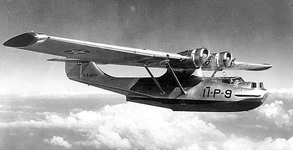
navigation. On July 6, 1920, the Navy had a Curtis-Felixstowe F-5-L flying boat, with "Radio Compass" equipment installed, fly out of the Hampton Roads area of Virginia (includes the city of Norfolk.) The F-5-L was to navigate entirely by Radio Compass to a rendezvous with the battleship USS OHIO that was at an unknown location at sea somewhere within a 100 mile semi-circular radius east of Norfolk and then to return, by Radio Compass navigation, to Norfolk. The USS OHIO was equipped with radio transmitting equipment and was sending out a "beacon" signal that the F-5-L received within minutes of becoming airborne. Once the bearing was established, the flying boat then flew in that direction for 90 minutes before sighting the USS OHIO at just under 100 miles off shore. The F-5-L crew circled the USS OHIO several times and then proceeded to use a land-based Navy radio beacon to navigate back to Norfolk. The demonstration proved that air navigation by "radio compass" was practical and needed to be developed further.

The Curtis-Felixstowe F-5-L was a large flying boat powered by two Liberty V-12 engines and piloted by a four man crew. The navigator was usually up front since at that time most aerial navigation was visual. Just in front of the wings was a double-cockpit for the pilot and co-pilot. Behind the wings was the radio operator's position. The radio gear was mounted inside the cockpit in a recessed area protected from the open cockpit environment but still accessible for the radio operator. It's unknown where the loop antenna was mounted.

The battleship USS OHIO had been decommissioned in 1918 but was put back into active service at the beginning of 1919 and sent to Philadelphia. It was used by the Navy for several experiments involving radio signals for uses other than communications. Besides the Radio Compass experiment, the USS OHIO also was part of an experiment to use radio to remotely control the operation of a radio-fitted target ship (using the old USS IOWA.) The experiment was to have the USS OHIO use radio signals to remotely operate and thus remotely "tow" the USS IOWA from Philadelphia to Hampton Roads, a task that was performed successfully. Due to its smaller size and age, along with its slow maneuverability, the USS OHIO was again decommissioned in 1923 and sold for scrap.  

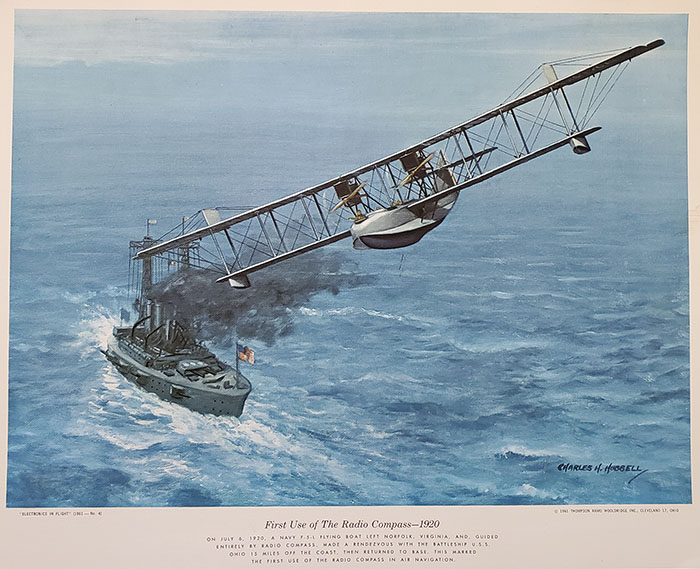
Shown in the header photo is an artist's depiction of the Radio Compass event titled "First Use of The Radio Compass - 1920." Charles H. Hubbell was a famous "aviation" artist who supplied the artwork for a series titled "Electronics in Flight" that was done for Thompson-Rand-Woolridge, Inc. in 1961 as part of a group of aviation-theme calendars. The calendar write-up that is below the artwork erroneously states the USS OHIO was 15 miles off shore. Had that been true, the crew of the F-5-L could have easily visually spotted the USS OHIO once they were aloft. The misprint probably was intended to read "95 miles." The entire write-up is below the artwork.

Department of Commerce - Bureau of Airways - Before 1925, nearly all air navigation was visual. Well-known landmarks were used, rivers followed, the few major roads were sometimes used as navigation landmarks. Airmail pilots were sometimes delayed when weather conditions obscured sighting landmarks that they used to visually follow their flying route. Some early air navigation aids were the large white arrows (usually made out of concrete) that were ground-mounted and placed in remote areas pointing the way to a specific airport. Later, large rotating beacon lamps were installed on towers usually in the same locations as the white arrows as navigation aids for night flying or poor visibility conditions. Navigating by Dead Reckoning was limited by the accuracy of the available instruments.

Early Airborne Navigation Radio Receiver Indicators - In 1926, the Department of Commerce, in charge of commercial flying through the newly created Bureau of Airways and Navigation, began to implement methods and equipment to utilize radio stations at airports to provide navigation information for pilots. The initial system was a non-directional radio beacon at the airport that provided a radio signal that allowed a pilot to use a radio to listen to the signal strength, try to determine the strongest signal response (by changing the airplane course.) The strongest response would generally indicate the correct direction of the airport. This system wasn't very accurate, it was difficult to use and it was thought that a visual indicator would be an improvement.

By the late-twenties, the airport radio beacon system had improved by using a directional beacon that employed an Adcock directional antenna that was comprised of four vertical towers in a 425' square with antennas in each corner. One transmitter would feed two diagonal antennas transmitting a signal modulated with 65hz and a second transmitter used the remaining two diagonal antennas sending an 85hz modulated signal. The antenna radiation pattern was a large "four-leaf clover" with the four main lobes providing the strongest signal and the minimum signal was between the lobes. The aircraft had to fly in the direction of the airport and on the correct minimal signal null (between the lobes.) The aircraft receiver-indicator was a system that used vibrating reeds within the pilot's instruments to indicate direction. The visual indicator would show equal vibration height of both reeds if the airplane was flying directly "on the beam" since both transmitted signals were at minimum. But, if the airplane drifted to the right then the 65hz reed increased in height because that radiation pattern lobe was being flown into. If the airplane drifted left then the 85hz reed with increase in height for the same reason. Which ever reed was showing increased vibration indicated to the pilot if he had drifted to the right or the left of the beam. The pilot had to fly in the proper direction of the airport and maintain the reeds equal in height to successfully navigate to the desired airport. The reed tips were painted white for increased visibility within the indicator.

By the mid-thirties, the vibrating reeds were being replaced with more modern systems of navigation that allowed the airports to use the same basic type of directional antenna system for beam navigation but the improvements were made to the transmitters used and also to the airborne DF equipment being used.

Radio Range Beacon Signals, Airport Range Beacon Antenna SystemsBy the mid-to-late 1930s, navigation from one airport to another airport involved flying the aircraft on a specific course at a specific altitude that was called an "Airway." The Airway was defined by Radio Range Beacons that were located at major airports and sometimes by Remote Radio Range Beacons that were in areas that were out of the range of any Airport Radio Range Beacons. Most Radio Range Beacons were able to be reliably received by aircraft out to a distance of about 50 miles. A major airport Radio Range Beacon would have more powerful transmitters and could be received out to 100 miles or more. The intersection of two different Range Beacon beams from two different airports could span a distance of up to 200 miles although most intersections were somewhat less than the maximum with 100 miles being average. Where the distance between two airports exceeded 200 miles then a Remote Radio Range Beacon station was sometimes installed to provide more consistent coverage. Where no Remote Range Beacon was installed the pilot had to know where the next Airway Range Beacon "beam" was using the navigation chart and then plot a heading to that point to intersect the next beam along the course. Well-travelled Airways, mainly in the Eastern part of the USA, would generally have consistent Radio Range Beacon coverage but, in the Western USA, consistent coverage was provided only on the busiest Airways.
 
Each Radio Range Beacon sent out a specific type of signal radiation pattern that was created by the type of antenna system used. The two types of antenna systems were the "Loop" which consisted of two large 300' long rectangular loops that center-crossed each other at right angles and were mounted about 30 feet high. The other type was the Adcock Tower antenna system that consisted of four 125' tall towers arranged in a 425' square with a tower in each corner. Although the Adcock four-square tower system can be used for DFing when combined with a goniometer, if the antennas are used as phased transmitting towers they create a specific type of radiation pattern (four-leaf clover pattern.) These tower antenna systems were sometimes called Modified Adcock Tower Antenna Systems or sometimes Range Tower Antenna Systems. The feedlines to these antennae were buried to help prevent skywave radiation and assure the the radiated patterns were accurate and consistent. The Radio Range transmitter was located in a building at the center of the square. An additional communications transmitter used a fifth tower in the center of the square that operated a different ground-to-air frequency than the Range Beacon used and was for weather announcements or voice communications to incoming airplanes. The Radio Range transmitter energized the Adcock "beam" antenna with a transmitter that operated in the 200kc to 400kc frequency range and was automatically keyed to produce a continuous string of dots and dashes. The output of the transmitter went to an automatically timed electronic switch that would allow a dot and a dash to energize one loop or one diagonal pair of towers to produce an "A" and then would switch to the other loop or pair of towers to allow a dash and dot ("N") to be sent.
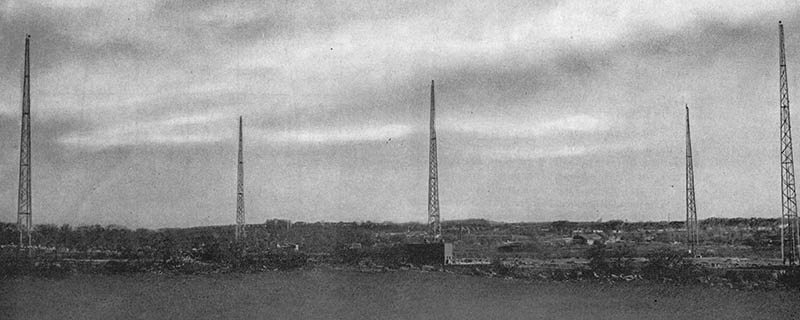
photo above: Maspeth approach to LaGuardia Field, NY showing the five tower Range Range Antenna system in 1943. Installed by Radio Receptor Co. - photo from "Highways of the Air"

The orientation of the two loops or the two diagonal pair of towers caused a "four-leaf clover" radiation pattern to be produced which resulted in four "nulls" in which the signal strength of the "A" and the "N" were equal and resulted in a continuous tone at the aircraft receiver. Each null or "beam" was 3º wide and, as mentioned, the signal could extend out an average of 50 miles and to over 100 miles for major airports. If the incoming airplane drifted off the "beam" one of the four-leaf clover antenna pattern lobes would become stronger and the pilot would begin to hear that letter much stronger and the other letter much weaker. As the airplane drifted more off the beam, the stronger letter would dominate. The normal procedure was that the "A" and "N" beams would combine when the airplane was "on the beam" and a continuous tone was heard although this information was only transmitted for around 30 seconds, then the Range Beacon's callsign was sent on the A loop and then on the N loop, then a long pause and then all of the information sent again (this format was continuously repeated.) The navigation charts would indicate the orientation of the A or N relationship to the four beams and that would indicate to the pilot or navigator which way the airplane had drifted allowing him to correct his course back onto the beam. As the pilot proceeded on course, when the airplane crossed over onto another Radio Range station signal the right-left orientation of the A and N would change because the airplane was headed away from the previous beacon and was now heading into a new beacon. This orientation change was shown on the sectional charts so the navigator or pilot would know and instantly recognize they were then correctly proceeding on the next Radio Range beacon and the callsign ID from the new beacon would verify the correct airway.

Many installations required adjustment to the radiated pattern due to the local terrain (to avoid mountain ranges or nearby hills along the course, for instance.) Sometimes in order to intersect with other Range Beacon beams, the radiated pattern required some directional adjustment. Usually a goniometer or a vario-coupler was used to alter the radiated pattern from one lobe or the other to adjust the pattern by "bending" the radiated "beams" as needed. Sometimes when only one beam needed to be adjusted, an excited parasitic antenna was placed within the antenna field to alter the radiated pattern of the desired lobe.

Position Markers, Fan-Markers, Cone-of-Silence Markers, Rotating Lamp Beacons - Since following the "beam" could result in the aircraft traveling perhaps as far as 100 miles, Position Markers were sometimes installed at various distances along each beam. Most position markers by 1940 were upward radiating VHF signals (most were on 75mc.) When received as the airplane passed overhead, the signal would be of very short duration so usually the marker signal would be modulated in a manner to actuate a switch in the radio gear that turned on an indicator lamp. Earlier position markers were designated as "M" markers and usually were on an adjacent frequency to the Radio Range Beacon and usually sent the same Morse ID call that the Range Beacon did. Because of the slightly different frequency and the lower power of "M" markers, they were easily identified by pilots. "M" markers were usually shown on nav-charts indicated by a circle with a "M" inside and the frequency of operation.

Fan-Markers were 75mc VHF position markers that were generally located mid-way along the airway beam or sometimes at locations where a different Radio Range "beam" intersected the beam being flown with the object being to specifically identify the beam that the pilot should fly on to stay within the Range Approach Channel (the flight corridor) to the airport runway. Sometimes Fan-Markers were placed to warn about obstructions ahead or to indicate the airport approach. Some Fan-Marker installations also had rotating lamp beacons and course lighting to visually aid the pilot as he approached the airport. Fan-Markers antennas produced a radiated pattern that resembled an "open fan" inline with the beam which allowed the pilot enough time to receive the information being transmitted as the airplane flew over the marker. Fan-Markers were usually shown on nav-charts as medium-size ellipses along the beam indication with the marker ID (usually a single letter sent in Morse) shown along side the ellipse.

Cone-of-Silence markers were located at the airport. As the airplane approached the airport, the "beam" signal would begin to "break up" at about one thousand feet out and could not be received at all directly over the airport. Cone-of-Silence markers were VHF transmitters (75mc) with an antenna that radiated a cone-shaped signal upwards with a modulated 3000hz tone that usually triggered an indicator lamp on the radio gear. The Cone-of Silence signal range depended on the aircraft altitude but at 5000 feet altitude the signal could be received out a little over 2000 feet. At 1000 feet altitude the range was about 1200 feet. The Cone-of-Silence generally indicated that the pilot was going to "over-shoot" the runway and should prepare for a turn after passing over the airport.

Usually, along the Airway course there were several rotating beacon lamps to aid in visual navigation at night. As mentioned, many times a rotating beacon lamp was also located at a Fan-Marker position. Some beacon lamps blinked in Morse to identify themselves and these types would have their Morse ID indicated on the Nav-chart. Sometimes there were also Inner and Outer Marker Beacons that were VHF types of position markers that indicated the distance to the runway of the airport mainly to help the pilot with the landing approach. Also, most airplane to tower communications were beginning to use VHF by about 1940 (128mc to 132mc at the time) but also had MW and HF capability (tower frequencies were indicated on the nav-chart.)

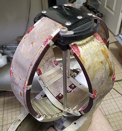
Right-Left Indicators - Some Radio Compasses utilized a visual indicator to show direction of drift off of a beacon signal that was being used for homing. Generally, the Right-Left Indicator was a center-zero meter that would be driven by the radio circuitry to move down scale (to the left) or up scale (to the right) in response to signal changes from the loop and sense antenna. The design used the omni-directional sense antenna's phase relationship to the variable phase relationship of the loop. At a loop null, the phase difference between the sense antenna and the loop is 90º but switches rapidly to 180º off the null. The induced signal voltage to the loop is at maximum when the loop axis is inline with the signal. When the loop is perpendicular to the signal the induced voltage is at minimum on either side of the loop. Within the Radio Compass circuitry, the loop input goes through an RF amplifier with a 90º phase-shifter circuit and into a dual balanced modulator (a dual triode circuit) that also has a 48hz audio oscillator driving one side of the balanced modulator. The output of the balanced modulator is inductively mixed and connected to the sense antenna where it is then fed into the RF amplifier of the receiver. From the detector/AVC/1st AF circuit of the receiver the signal is routed to a 48hz AVC amplifier and a Compass Output stage and these two signals are inductively coupled to the R-L meter. The R-L meter is a special dual coil unit (dynamometer) with a field coil and a moving coil. Since the field coil is driven by the 48hz audio oscillator and the phase shifter/balanced modulator is also driven by the 48hz audio oscillator driving the moving coil, when the loop is at a null the phase difference is zero and the meter stays at center. If the airplane drifts "off the beam" it appears to the Radio Compass circuitry that the loop has changed position and thus the phase changes with the result that the R-L Indicator moves to either the right or the left depending on where the beacon is in relationship to the airplane's new course. By keeping the R-L Indicator needle centered, the pilot or navigator was assured that the airplane was flying "on the beam." NOTE: This is a description of how the Bendix Radio Compasses functioned.

Finding the Aircraft's Position - Most of the time, an airplane flying in an Airway to a known destination was always having its position known and logged by Air Traffic Control associated with the various Airports and certain Radio Range stations. Usually, this information was automatically exchanged with the flying airplane as it passed certain Radio Range stations. Information on "fixes" were exchanged between Air Traffic Control centers and Radio Range stations most of the time, so usually the pilot and Air Traffic Control knew where the airplane was at all times. If the airplane was not flying "on the beam" but was at an unknown position for some reason (like out at sea flying towards the coast) it was relatively easy for the pilot or navigator to quickly get a "fix" on the airplane's position. Using the Navigation Chart, an appropriate beacon was selected. The nav-chart showed the location, frequency and call of the beacon so tuning it in on the DF receiver was easily accomplished. Using the Homing loop a bearing was taken on the null (it didn't matter which null was selected) and a line drawn on the chart referenced from the beacon's location. Then another nearby beacon from a moderately different location was selected, tuned in and a bearing determined. When the second line was drawn on the chart, the point of intersection of the two lines indicated the airplane's position. This was relatively accurate but since the airplane was traveling in a specific direction at flight speed, the faster the triangulation was performed, the more accurately the position could determined. AM-BC stations were usually shown on nav-charts because their strong carrier signal could easily be used as a beacon for Homing or for triangulation. In some areas during WWII an Army Air Forces (AAF) aircraft could radio they needed a "fix" at which point a AAF master control station would quickly start the process and the aircraft's position was then radioed back with the suffix QTF to identify the message. An aircraft could also request a magnetic course steering (QDM) or a true course steering (QUJ) and the master control station would start the process of a course change calculation (either referenced to magnetic compass QDM or referenced to true north QUJ) that was then radioed back to the aircraft. There were other methods (non-radio) also used to determine position that involved measuring the sun's position versus the time of day and course direction. Stars could be used if the airplane was flying at night.
Aeronautical Navigation Charts and Computers - There were different charts for daytime or nighttime flying with different map projections, e.g., Mercantor for nighttime flying and Lambert for daytime flying. Mercantor projections are purposely distorted to present square map grids but as the distance increases the distortion errors increase and a correction factor had to be added or subtracted to the course. The nighttime charts were simplified with no landmarks shown other than those that would be visible at night. Additional information shown on navigation charts included marine beacon calls and frequency, weather station calls and frequency, AM Broadcast station calls and frequency, general terrain and elevations, latitude and longitude, major visual navigation points (roads, railways, lakes and rivers,) other visual indicators such as tower lights that included rotating lights, lights that blinked Morse, or other types of lighted beacons. By the early 1940s many nav-charts would show a Range Approach Channel that was a corridor that pilot was to stay inside of while on the "beam" as the airplane approached the airport and runway. Some Range Approach Channels would intersect with different beams and channels if the course required the pilot to make a turn onto another beam to follow to a specific approach to the airport. Generally, if the chart was intended for in-flight use it would be an Air Navigation Sectional Chart that covered about a 300 mile "section" of a specific area of land with many details about airports, beacons, topography, etc., to aid flight navigation. If the chart was intended for ground use or reference for flight planning it was a Radio Direction Finding Map which covered a much, much larger area (like the entire Southwest or the entire Northeast of the USA) and the details were more general, usually showing Radio Range Beacons but not showing the A or N quadrants. Markers, course lights, lamp beacons, etc. likewise, were not shown since the scale of the map covered such a large area.  

Navigators usually were equipped with several types of tools that were usually kept in a kit and included many types of scales and protractors with articulated pointers, usually made of transparent plastic, for placement on top of charts. Also included were various types of calculators (sometimes called "computers" but most were like circular slide rules and able to perform several calculations or conversions simultaneously.) Some tools had combinations of transparent articulated pointers and sliding scales for calculating variables or position. These calculators, scales, protractors and conversion tables helped to speed-up the process and hopefully increase navigation accuracy.

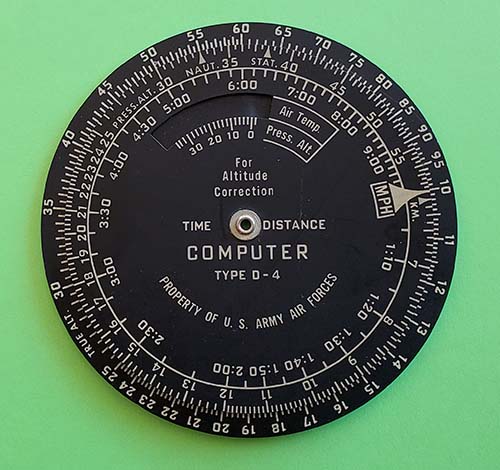
photo right: A "Time-Distance" computer, Type D-4, from WWII, for the USAAF.
 Diameter of this device is 4 inches. There are more computation scales
 on the backside of this Type D-4 computer.

Aeronautical Charts - 1938 to 1947
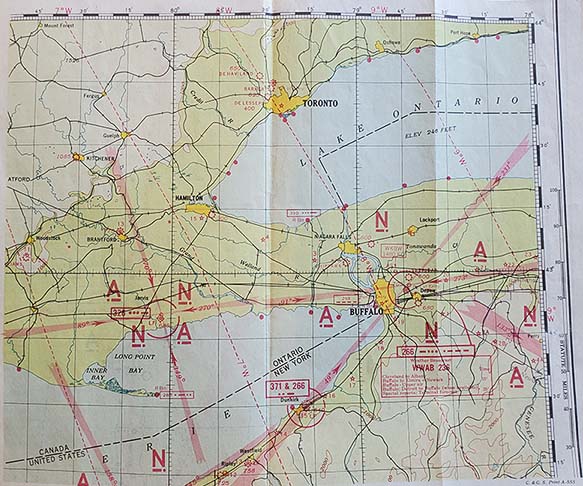
1938 Air Navigation Chart


1938 BUFFALO, NY area. The Range Beacon "beams" are shown as four light-red spokes emanating from the airport location. Note how the Buffalo Airport's Range Beacon antenna pattern has been "bent" to match other Range Beacons in the area. Also, note that the course approach bearing is shown in degrees inside each spoke and each quadrant has the A or N identification shown. Each airport beacon also has the frequency shown in kilocycles and the call shown in Morse.

Note that Buffalo AP Range Beacon is on 266kc and the call is BJ shown in Morse. Also, IT at Dunkirk is a Position Marker that indicates another beam's intersection on the BJ 49º approach beam. At this time in 1938, the Position Marker (if even present) would send its call on both 371kc and 266kc. VHF was used for Markers by about 1941.

Also, note that weather broadcasts are on WWAB on 236kc. WKBW 1480kc is an AM-BC station shown north of Buffalo.

Magnetic Variation is shown as the dotted arced red vertical lines with degrees and direction indicated. Magnetic Variation is also shown in red within the latitude and longitude markings on the map's edges. 

Stars, solid circles and spoked wheels indicate visual beacons such as rotating lights, etc. Star within a circle indicates a marine beacon with call and frequency shown within a rectangular box. Most nav-charts contained a wealth of information for the pilot and navigator. 

1943 Air Navigation Sectional Charts


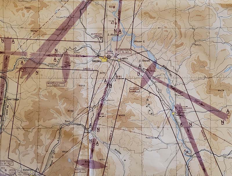
1943 HELENA, MONTANA area. AP Radio Range Beacon is HL on 371kc. The ellipses indicate a Fan Marker on 75mc indicating either airport approach or other information. Almost all of the Fan Markers will also have a rotating lamp beacon at the marker location and course lights. North on 165º beam note rotating lamp beacon 42 with the Fan Marker "U" and also East on 279º beam a similar lamp beacon with the Fan Marker "W" identified as 1. These lamp beacons associated with Fan Markers also had course lights showing the pilot the runway direction. Note the Radio Approach Channels are identified by colors, e.g. GREEN 2, AMBER 2, etc. Each beam has the A or N quadrant identified. Most of the beams intersect with beams from other Radio Range Beacons to provide the pilot with almost constant navigation direction signals. The dotted line in the upper left indicates Magnetic Variation which in this area was 20ºE. Stars indicate a lamp beacon. Stars with arrows indicate a rotating lamp beacon with course lights. Gear-shaped circle indicates an airport. Note that TOWNSEND "V" is a lamp beacon with course lights but not a Fan Marker. The course lights directed the pilot to the intersection from 319º from Bozeman to 279º from Helena. Airport elevation is the italic number. Various shades of brown colors indicate elevation between 3000 and 5000 feet. Charts had to be carefully studied before the flight began since so much information is presented on each chart. This is just a small area of the particular sectional Air-Nav chart which is 42" x 24" in size.


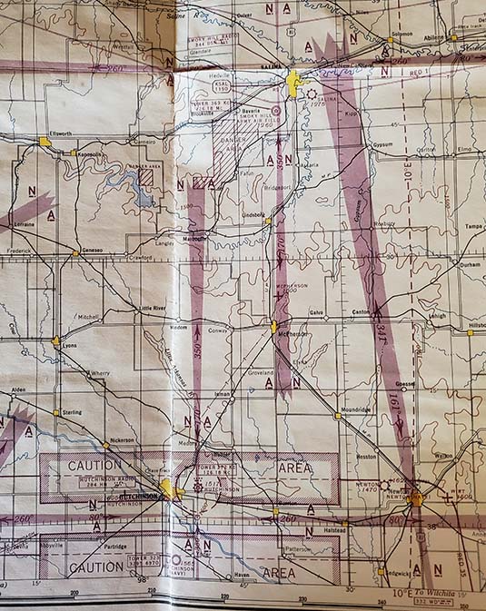
1943 SALINA, KANSAS area showing Salina AP, Smokey Hill Army Air Field, Hutchinson AP and the Hutchinson Navy Air Base. The shaded borders marked CAUTION AREA indicate that the pilot should avoid this area, if possible. Note that near Salina is a marked DANGER AREA southwest of the Smoky Hill Army Air Field indicating this area is not to be flown over. The Hutchinson AP Tower is on 272kc and on 126.18mc while the Radio Range Beacon is on 284kc with the call HS. Note that west of Salina is an AM-BC KSAL station tower operating on 1150kc. Since the elevation in Kansas is between 1000 feet and 2000 feet the map color is white. This Aeronautical Navigation Section Map measures 42" x 24" and covers the central portion of Kansas. These Section Maps might seem large for single seater airplanes but the pilots had their routes planned and generally folded the map up with just the necessary areas showing. In larger planes with navigators it might have been possible to have the map fully unfolded. 

1947 Aeronautical Map for Radio Direction Finding
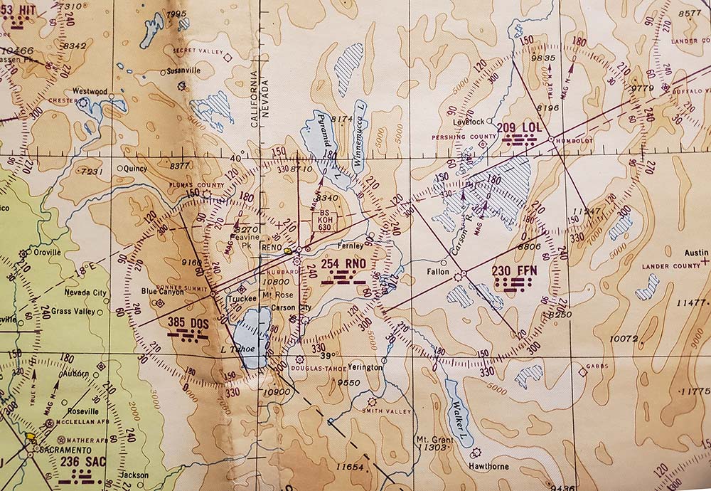
1947 RENO, NEVADA area. Reno AP Radio Range Beacon is RNO on 254kc. Note that the AP is "Hubbard Airfield" which was at sometime purchased by United Airlines and then sold to the City of Reno in the 1950s.

KOH is shown on 630kc - on that frequency from 1940 up to about 1990 (now on 780kc.)

LOL on 209KC was a Remote Radio Range Beacon located east of Lovelock, Nevada.

FFN on 230kc was the Radio Range Beacon SE of Fallon, Nevada

Of interest is the Remote Radio Range beacon located on Donner Summit DOS 385kc.

Radio Range Beacon patterns show the four beams within a 360º compass rose with 0º indicating magnetic North. Beams could be the referenced to the compass rose shown to indicate the beam heading. Note that both Magnetic N and True N are usually shown on the compass rose with True N plotted for the magnetic deviation. The dotted red line indicates Magnetic Variation which is 18º E in this area.

Circles with stars inside indicate a military air base, e.g., McClellan AFB or Mather AFB near Sacramento. Gear-shaped circles indicate a municipal or commercial AP.

This map is for the entire Southwest US so only a small portion is shown in the photo. Much larger areas are shown in Radio Direction Finding Maps compared to Navigation Sectional Charts since the DF Map isn't necessarily for in-flight navigation. Also, DF Maps won't have the A or N quadrants indicated on the compass rose of each Radio Range Beacon for the same reason. The elevation is indicated by color with browns being above 5000 feet. Note that below 3000 feet is green (Sacramento.) The entire map measures 36" x 26" and the map grid is shown in the Lambert projection.

Radio Range Beacons started to be replaced with the VOR navigation system by the early-1950s and very few Radio Range Beacons were left by the 1960s.

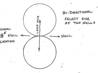
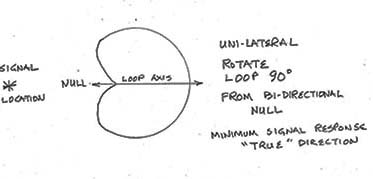
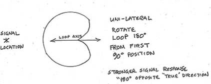
"Homing" Bi-lateral Directional Uses - When the aircraft was flying towards a "known location" beacon, then Bi-lateral (aka: figure-8 pattern) was used and the loop locked in position perpendicular to the fuselage (athwartship) and the airplane course determined by steering the airplane in the direction of the bearing of the minimum signal response. This was called "Homing." An Audio Output Meter could be plugged into one of the aircraft receiver's phone jacks to use as a visual indicator of minimum signal response. Since the Range Beacon's call and location were shown on the navigation charts, Bi-lateral allowed "beam navigation" and kept the airplane on course within a defined "Airway" to the airport or city that the beacon was transmitting from. The "Airway beams" locations and bearing directions were also shown on the navigation charts along with the "between the beams" signals of "A" and "N" Morse (MCW) identifiers to indicate via the radio signals and by the navigation charts where the airplane was in relation to the four fairly narrow navigation "beams" from the Airport Range Beacon transmitter/antenna system. The "A" and "N" beam loop IDs would combine when the airplane was "on the beam" and a continuous tone was heard although this information was only transmitted for around 30 seconds, then the Range Beacon callsign was sent on the A loop and then on the N loop, then a long pause and then all of the information sent again (this format was continuously repeated.) Non-directional Beacons could also be used for "homing" in the same manner. AM Broadcast stations were often used as homing beacons where there weren't any Range Beacons (like out at sea coming into land.) Most AM-BC stations were shown on the navigation charts with location and frequency for just such purposes.

Dead Reckoning - Only the largest and busiest Airports had all of these types of radio navigation installations. Small airports might only have a radio beacon like a non-directional beacon that allowed a pilot to find the airport using a "Homing Loop" type of navigation along with visual navigation. Usually there was some type of ground communication although it might not be with an airport tower. During WWII, a lot of air traffic in the USA used Airways navigation but in other countries or perhaps small islands only small temporary or "make-shift" runways might be used. Navigation in these areas might be able to rely on crude beacons or other methods to determine the runway's location from some distance out. With small runways without beacons or in other types of flying that might be reconnaissance or similar missions, the pilot or navigator could plot a course to that airport or area and then use "Dead Reckoning" to fly there. Dead Reckoning used the plotted bearing, the calculated distance, the air speed, the altitude, any crosswinds and the aircraft's magnetic compass to estimate a fairly accurate course to the small airport. Once on course, then visual navigation could also be used and landmarks shown on the navigation charts could be used to verify the course accuracy.

Other Systems Used During WWII - Most bombing missions were navigated by Dead Reckoning in that from the airbase where the bombers took off to their destination was a specific course that was determined in advance. The course would require corrections and may require bearing changes but most of that would be predetermined. Besides the bearings and the airplane compass, air speed, wind speed and direction, altitude and other factors were all needed to determine target arrival time. General visual indications were used to identify the target upon arrival during a daytime mission. The return trip used other pre-determined courses with appropriate bearings already known. This all worked fairly well if it was daytime. But, if at all possible, nighttime bombing was more advantageous for the bombers since it was more difficult to spot them in the sky. For nighttime bombing, there were methods used by the Germans in occupied France during WWII that utilized directional antennae with a very narrow beam that could be aimed at cities in England. The German bombers would fly the "beam" towards the target city and at a certain point along that beam an intersecting beam sent from a second German station also in France would indicate that the target city was directly ahead. Throughout Europe there were MW-AM-BC stations, LW BC stations and various types of radio navigation beacon signals being transmitted that could be used for bearings. The airway beams used in Germany during WWII (and before) were somewhat different than the Radio Range Beacons used in the USA. The Germans transmitted very narrow beams on each side of the airport runway. One beam sent only dashes, the other beam sent only dots. When the approaching airplane was "on course" the pilot or navigator would hear a constant tone. Any deviation right or left would result in hearing either dots or dashes and the pilot could then correct as necessary. Nearly all of these enemy navigation signal sources were known and the frequencies with signal descriptions were published by the military in booklets for reference by pilots and navigators. Of course, these signals could change or they might also be deceptive in nature so while they were generally "known" they were only used in emergency situations. The pilots and navigators would rather rely on their own beam signals (if any,) their own instruments and calculations for bearings and courses.


Radio Direction Finding Equipment - "Homing"


Navy Department - Western Electric Company

RU-Series of Aircraft Radio Receivers

Model RU-16  Type CW-46051A
 

The earliest RU Series of aircraft receivers date from about 1930. The early models were built by Aircraft Radio Corporation. The receiver evolved throughout thirties and, although the design was certainly showing its age by WWII, the last contracts are from 1941 (for the RU-19.) Like all pre-WWII equipment, contracts were for very small quantities so the early versions are very rare. The most commonly seen RU versions are the RU-16 which were produced in fairly large quantities in the very early part of WWII (but apparently not used extensively in actual service compared to the contract quantities produced.) The contracts actually date from before WWII began for the USA, April 21, 1941 with Western Electric Company as the contractor. The RU-16 operated on +12vdc implying that the installation would be in earlier types of aircraft. By 1941, +12vdc aircraft power was quickly being replaced with the more efficient +24vdc power.

The intended use for the RU receiver and the GF transmitter equipment was in single-seater or two-seater airplanes (radio op/observer seated behind the pilot) but the manual also mentions "flying boats" as another possible user in the installation instructions. Each installation into an particular airplane was "custom fitted" with each of the connecting cables custom-built from supplied "bulk cable." Additionally, flex control cables were also custom-fitted and were built from supplied "bulk" flex cable material. In some single-seater airplanes, the only place to install the radio gear was behind the pilot's seat so remote controls using flex control cables and spline drive flex cables along with remote switch boxes and tuning heads were installed to allow the pilot to have the essential radio controls in front of him. There is also evidence that some RU-16/GF-11 gear was installed into a few small Navy boats and that some vehicular installations may have occurred from time to time. The USMC is said to have had some vehicles equipped with RU/GF gear. Not all RU-Series receivers were paired with the GF-Series transmitters. The RU-18 was usually paired with the much larger GO-Series transmitters. Some RU-Series receivers were setup in "receive only" stations while others might just be used for DF purposes. All RU receivers could be used with a loop antenna for the purpose of homing. Homing loops for the RU receivers had to be bi-directional (figure-8 pattern) without a center tap. Also, ZB Homing Adapters were designed to work with the RU receivers and provided VHF homing capability utilizing a special type of signal sent from aircraft carriers (more info in ZB Homing Adapters further down this page.) 


photo above
: RU-16 Receiver - serial number 8989

There were also U.S. Army versions of the RU/GF equipment designated as the SCR-AL-183. The receiver was the BC-AL-229 and the transmitter was the BC-AL-230. The contracts are from the late-thirties up into 1940 with Western Electric as the contractor. This equipment is very similar in appearance to the RU/GF equipment but internally both the receiver and transmitter abound with minor differences. The SCR-AL-183 was the 12 volt version and the SCR-AL-283 was the 24 volt version. The Army versions were also intended for one and two-seater aircraft installations and are found in both black wrinkle finish and in bare aluminum.

The overall use of the later equipment was very low by mid-WWII. This non-use resulted in many complete RU-16/GF-11 equipment packages being sold on the post-WWII surplus market "new in the box" which accounts for the "fairly common" status of the RU-16/GF-11. The RU-17/GF-12 were the 24 volt versions and apparently this equipment was used much more extensively during WWII and isn't encountered as often as the RU-16/GF-11. For quick identification the data plates on the 12 volt units had a black field while the data plates on the 24 volt units used a blue field.

RU-16 Receiver Circuit - The earliest RU receivers used triode tubes in a TRF circuit with tracking BFO. A tracking BFO utilized an identical section of the main ganged tuning capacitor along with coils that allowed adjustment of an oscillator to "track" or "tune along with" the tuned RF frequency accurately. Usually, a tracking BFO would be set one kilocycle higher than the RF tuned frequency to allow a heterodyne to be audible, allowing demodulation of a CW signal. All early RU receivers were built by Aircraft Radio Corporation. The early RU versions didn't have an AGC circuit. Additionally, tuning range was limited by the few available coil sets. By early 1941, the RU-16 had been designed. It was the first version of the RU to use an AGC circuit. Six tubes are used in the RU-16 circuit which is still a TRF (tuned radio frequency) receiver with tracking BFO. The tubes used are 1RF - 78, 2RF - 78, 3RF - 78, AGC - 77, Detector - 77, AF Out/BFO - 38233 (aka 1642.) The last tube, type 38233/1642, is a dual triode that provides the tracking BFO with one triode and the Audio Output stage with the other triode. The plug-in coil assemblies each contain five shielded coil units - four units that determine the RF tuning range of the assembly and one unit for the tracking BFO coil required. The "dual frequency range" coil assemblies contained an internal switch that was operated by lever located on the front of the assembly. The single range coils had a metal handle-type strap for removing the coil from the receiver. Shown in the photo to the right is the GF-11 transmitter and the RU-16 receiver with control boxes and test meter.

Antennas - There are two antenna inputs, A and L - L. The L - L terminals are for a "homing loop" antenna. The Antenna or Loop switch could be set up to operate locally at the receiver or remotely via a flexible cable. The A terminal could be connected to any of the typical aircraft antennae available and depended mainly on what type of airplane was involved. Most single-seater airplanes had a wire antenna from the cockpit to the tail. Two-seaters usually had an aerodynamic mast near the airplane nose with a wire running to the tail. A central wire dropped down beside the rear-seat part of the cockpit and entered the side of the fuselage for the radio gear connection (a "T" antenna.) Some installations used a trailing wire (depended on the aircraft.) Although it was possible to use a "True Direction" type of loop, such as the DW-1, with the RU, the most common DF application was for homing using a simple non-center tapped loop antenna.


Navy Department - RCA Manufacturing Co., Inc.

Aircraft Radio Receiver - Model ARB - Type CRV-46151
 

The ARB receiver was a six tube superheterodyne receiver intended for use in USN aircraft. It was an updated version of the earlier, mid-thirties RU receiver series that required several sets of plug-in coil assemblies to change tuning ranges in addition to a baffling array of remote boxes, remote cables and a junction box for interconnection of all of the extra pieces. The ARB receiver simplified the hook-up and dramatically improved the overall performance by replacing the RU's TRF with Tracking BFO circuit with a superheterodyne circuit. The ARB receiver tuned from 195kc up to 9.05mc in four bands. Two dual-frequency IF amplifiers are utilized with 135kc used in the 195kc to 1600kc range and 915kc used from 1.6mc to 9.05mc (a dual frequency BFO was also required.) The receiver used 12 volt heater tubes (in series-parallel for 24-28 volt operation) and had one RF amplifier 12SF7, a Converter 12SA7, two IF amplifiers, both 12SF7, Det-AVC-1AF stage 12SF7 and an audio output stage 12A6. A neon bulb was used as a voltage regulator for the LO part of the Converter stage. The lower two bands could be set up for loop operation, specifically for homing DF purposes. All four bands could be used for Communications and operated with the various types of aircraft antennae available. To simplify the external power hookup, the aircraft +28vdc buss was connected to POWER for tube heaters and inside the ARB was a dynamotor that provided the +230vdc B+.

The ARB was designed for either single-seater (pilot only) or two-seater aircraft (pilot and radio op) but could also be found in larger aircraft with a crew that included radio op/navigator, pilot and co-pilot. Modes of reception were CW, MCW and Voice with the options of AVC or MVC (Manual gain control.) When in "AVC," the Volume control operated as an AF gain control with RF/IF sensitivity controlled by the AVC line. When in "MVC," the Volume control operated as a RF/IF gain control with the audio gain set to maximum. Selectivity options when in AVC were either Sharp or Broad. The "Broad" position was intended to ease tuning in the 1600kc up to 9.05mc range where signals tended to be more difficult to "tune in" due to the wide span of frequency coverage in each of the two bands (additionally, the remote receiver tuning head was particularly difficult to "fine tune" due to flexing of the cable drive which resulted in significant "backlash" if not installed correctly.)

The initial ARB receivers are pre-WWII and were used for Communications and for Homing DF. For DF, the aircraft had to be equipped with a rotatable, non-center-tapped, loop antenna that could be connected to the ARB receiver terminals marked L1 and L2 (L2 is chassis ground.) When connected in this way, the loop would be operational only on the two lower frequency bands only (195kc to 1600kc.) This type of loop antenna would have a bi-directional "figure-8" pattern and was generally set "athwartship" and the airplane steered towards the minimum signal response (homing.) The two other antenna terminals are marked AT and AF. AT indicated a "Trailing Antenna" which was normally installed in larger aircraft and consisted of a copper-clad stranded steel cable with flight weight that could be reeled out to about 200 feet behind the aircraft when in flight. AF indicated "Fixed Antenna" which was a smaller antenna consisting of an off-center fed wire between the cockpit and the tail of the airplane or it could be a short vertical installed on larger aircraft (usually 4 to 5 feet tall maximum.)


photo above
: ARB Receiver on its shock mount (hard to see) with ZB-3 Homing Adapter on top, Operator's Control Box and Receiver Tuning Head to the right. On the Operator's Control Box, the unused connector plug marked "Control Box" would be used for the wire cable running to the Pilot's Control Box. The opening with the threaded barrel is for the Bowden cable that ran to the cockpit to allow the pilot to switch control of the receiver from "REMOTE" back to the radio operator, "LOCAL." Dual phone jacks could be used for two sets of 'phones or one jack could be used to operate an Audio Output Meter for DF purposes.

The Control Boxes - To actually operate the ARB receiver required the Operator's Control Box (Type CRV-23256) or the Pilot's Control Box (CRV-23254.) The receiver could be operated by either of the control boxes when the aircraft installation was for "dual control setup" required for radio-navigator or pilot control. There wasn't a volume control on the receiver but each control box had a volume control. Likewise, there wasn't a phone jack on the receiver for audio output and, again, the control boxes had dual phone jacks for audio output. Normally, the audio output impedance was set for LOW which was 600Z ohms. By moving a pair of jumpers in either control box the audio output impedance could be set to HI or 4000Z ohms. Either control box could also switch bands on the receiver remotely when the receiver's "MOTOR" switch was ON as this enabled the receiver's motor-driven band switch. This function could be disabled with the receiver front panel "MOTOR" switch and the band switch on the receiver then operated manually.

The Operator's Control Box had a port with a threaded barrel for installing a bowden cable that mechanically connected internally to the "LOCAL-REMOTE" switch. If the radio op wanted to pass control of the receiver to the pilot, he switched the lever to "REMOTE." This operated the bowden cable and pushed the bowden cable knob at the pilot's location to the "up" position. Through the inter-connecting wire cable the Pilot's Control Box electrically was activated and the Operator's Control Box was deactivated. The Pilot's Control Box now allowed the pilot to have control of receiver operation. Additional to this "dual control setup" was a second (flex cable connected) Receiver Tuning Head that was installed in the cockpit near the pilot. This setup allowed the pilot to tune the receiver, switch bands, control gain and select reception mode. To pass control back to the radio op, the pilot would push down the bowden cable knob and that operated the Operator's Control Box "LOCAL-REMOTE" switch via the bowden cable returning control back to "LOCAL" and activating the Operator's Control Box and deactivating the Pilot's Control Box. Where the installation only required the pilot to operate the receiver then just the Pilot's Control Box could be installed and it would provide normal operational control of the receiver by a single operator.


 photos: The Pilot's Control Box CRV-23254 (left) and the Operator's Control Box Type CRV-23256 (right.) The Operator's Control Box adds the LOCAL-REMOTE switch.


photo above: Close-up of the Receiver Tuning Head Type CRV-23253

The Receiver Tuning Head -  Receiver tuning was accomplished by using a Receiver Tuning Head (Type CV-23253) that had a conical tuning dial scale viewed behind an index window and a hand crank type of tuning control. Coupling to the receiver was via a metal flexible spline-ended cable in a metal flexible housing (similar to the speedometer cable used in older cars.) There was also a direct coupler that could be attached to the receiver tuning gearbox that allowed direct "at the receiver" tuning utilizing the receiver dial for frequency readout but the dial scale was minuscule so a magnifying lens was built into the dial bezel.

Additionally, the direct coupler had a "feed-thru" connection that allowed the direct coupler and the receiver tuning head to be connected together and to simultaneously operate the receiver tuning (this setup tends to compromise the otherwise smooth operation of the Receiver Tuning Head.) Hint: For smooth tuning operation don't over-tighten the collar nuts on any of the flex cables or couplers. Also, avoid "tight" bends in the routing of the flex cable with no radius tighter than 6" for best results. Securely mounting the flex cables and tuning heads will also help significantly by keeping all parts in a stable, fixed position.

Ancillary Parts
- The ARB used one power cable, one control box cable, one flexible tuning (spline-ends) cable, one "Pilot's" control box, one remote tuning head, a shock mount and phones. It was also possible to setup for "dual operation" by adding an "Operator's" control box and control box cable (connected to the first control box) along with a second flexible tuning cable, "T" coupler and second tuning control head for larger aircraft where either a navigator or radioman was aboard. A bowden cable was also necessary to allow switching from "Remote" to "Local" control from the pilot's position.

Operational Notes - It's NOT a Ham Receiver - A very selective IF bandwidth was not really desirable in a WWII aircraft receiver that might be operated solely by the pilot. Quick location of the desired signal (a homing beacon, for example,) with a minimum of operational movements was necessary. Also, interference was practically nil in normal operations at the time. Today, if one is trying to use the ARB as an AM ham station receiver, they will immediately find that the IF passband is extremely wide, even in the SHARP position (at least 10kc bandwidth in SHARP.) The ARB is certainly sensitive enough but adjacent frequency signals will be heard and sometimes these adjacent signals seem to overwhelm the desired signal. A small separate receive antenna might help reduce some QRM. Also, a loop antenna might allow "nulling" the offending QRM however most homing loops were for MW or LF operation. The use of preselectors or converters only seems to complicate the set up for a receiver that wasn't designed for and was never intended for voice ham band operations. Although the same selectivity problems naturally exist for CW operation the lack of CW activity (in the CW portions of the HF ham bands) these days generally results in QRM-free operation in the CW mode.
 

Initial Concept of Homing DF with the ARB - The ARB was originally intended for use with a non-center-tapped loop antenna that allowed one end of the loop to be grounded. These loops responded in a "figure-8" or bi-directional pattern and could provide a bearing by DFing a known beacon signal to allow "homing-in" on the signal. This provided the pilot or navigator with a very accurate bearing towards the origin of the "known" signal. The bi-directional pattern allowed for two "deep" nulls off each side of the loop. The nulls were much easier to detect and much more accurate for determining the "minimum response" at specific loop positions. Since the Operator's Control Box had two phone jacks, an Audio Output Meter could be plugged in to allow an accurate visual indicator for minimum signal response. Though "true" direction might be ambiguous since there were two nulls, generally the pilot and navigator knew the approximate direction of the airfield they were flying to and the loop's null gave them a precise bearing toward the airport's Range Beacon. Pre-WWII, there were many Remote Airways Radio Range beacons along with regular Airport Range Beacons that provided navigation radio DFing signals to allow the pilot or navigator to determine the correct course (called an Airway) to fly to a desired airport. Once the airplane was "on course" using one of the four "beams" from the beacon, then the "A" and "N" signals in combination (a constant tone) along with the navigation chart indications allowed following an accurate course to the airport. In cases where only a non-directional beacon was available for navigation, the pilot or navigator would set up the loop athwartship to allow navigating the aircraft to a desired airport or other location. Sometimes an AM-BC station would be used for a beacon since their signals were usually strong and consistent and the transmitting location (city) was known. All beacons and most strong AM-BC stations were shown on the navigation charts. AM-BC stations were supposed to identify themselves with their call and city location at least once an hour to assist any aircraft that were using the AM-BC station as a beacon. When the airplane involved was from an aircraft carrier at sea then the following piece of equipment allowed the pilot to find his way back to the carrier if his distance out was too far for visual or if it was at night.  


photo above:
ZB-3 Homing Adapter
. Installing the ZB Homing Adapter on the RU receiver required removing the RU vacuum tube cover. The ZB shock mount holes and slide-clips align with the mounting pins that were for the RU vacuum tube cover. The ZB shock mount plate doubles as a RU vacuum tube cover when installed. There were two "slide latch" pins on top of the ARB cabinet to allow for the installation of a VHF homing receiver such as one of the ZB-Series (ZB, ZB-1, 2 or 3.)

 Navy Dept.- Contractor: Western Electric - Mfg by: Zenith Radio Corp.

Model ZB-3 Homing Adapter  - Type CZR-69076

The ZB-Series was actually designed in the late-thirties for use with the RU receivers but were later also installed on ARB receivers. These Homing receivers used four 954 acorn-type tubes and received direction-location signals transmitted by aircraft carriers. The aircraft carrier transmitted a homing signal using a small rotating VHF beam antenna mounted high up on the carrier's superstructure that sent out a signal that was "timed" to send specific but differently coded signals every 30º of rotation (speed of rotation was fairly slow at about 3 rpm.) This would allow identification of each 30º sector by a pilot using a "homing adapter" and radio receiver to ascertain an accurate and specific direction to the aircraft carrier. VHF was used since the radio wave was highly directional with the antenna used producing a very narrow beam width that wasn't affected by propagation. The actual signal was comprised of a VHF carrier wave that contained a modulated subcarrier of 700kc. The sub-carrier was modulated with MCW signals consisting of various Morse letters that identified 12 sectors separated by 30º increments of a 360º degree circle surrounding the carrier. The ZB receiver would initially receive the VHF signal which was then down-converted so it could be received on the RU or ARB receiver in the airplane when tuned to 700kc. The pilot had to know which letter identified which 30º sector around the carrier relative to his flying position (for security, these codes changed daily.) The strongest signal indicated in which sector the airplane was flying and this allowed the pilot to calculate where the carrier was and how to approach the landing deck. Depending on the aircraft's altitude, the homing signal could be received out as far as 275 miles away. Use of the ZB Homing Adapters allowed pilots to find their way back to their carrier from long distances, or at night or in otherwise very poor visual conditions.

The ZB-3 Homing Adapters would receive the VHF "homing signal" from the carrier transmitter that usually operated around 242mc. The converter of the ZB receiver would then subtract the VHF carrier leaving the sub-carrier and modulation. The MW sub-carrier wave could then be tuned in on the ARB receiver (or the RU receiver.) If the VHF carrier wave was intercepted by the enemy, no information could be detected without the ZB-type conversion taking place. There were other ZB Homing Adapters at other frequencies, for example the ZB-2 utilized frequencies in the 34mc to 58mc range while the ZB-3 utilized frequencies in the 234mc to 258mc range with the normal operating frequency being 242mc.

The ZB Homing Adapters required a specific ZB-Control Box that routed power from the ARB receiver or from the Junction Box in the case of RU receivers. A specific ZB-Antenna Relay Box was also required and that allowed switching RF signals to the ARB (either from the Homing Adaptor or from the MW or HF aircraft antenna.)


photo above
: The ZB-3 chassis showing the voltage selector switch on the right (some RU receivers operated on 12vdc.) Also the antenna input coaxial cable going to the 1st RF amplifier stage. The next two stages to the left are the second and third RF amplifiers. The left side last tube is the converter/LP filter circuit.

The rear panel ZB connectors are routed as follows: The three-pin connector cable is routed to the ARB accessories socket or the RU Junction Box. The four pin connector cable is routed to the ZB-Antenna control box. The eight pin connector cable is routed to the ZB-control box. These connections allowed the ARB or RU to be used for "Homing" or for communications. Also included in the ZB accessories was a test oscillator with VHF output. The "snap pins" on top of the ZB are for the canvas cover (called a "skirt") that could be installed when the ZB wasn't in use.

Later versions were given the designations of ARR-1 and ARR-2. The ARR-1 is very similar to the ZB-3 while the very late versions of the ARR-2 used an on-board dynamotor and flexible cable remote tuning control.


photo right: Rear of the ZB-3 showing the various receptacles.


Search and Rescue Operations:

 Determining True Direction of Radio Signals
 
Originating from an Unknown Location


Most Airways navigation involved flying "on the beam" which was done using the Homing Loop position with the loop set athwartship and steering the airplane towards the Radio Range Beacon with listening and watching for Position Markers as the course was flown.

Most "Search and Rescue" operations involved using the loop antenna in combination with a sense antenna to produce a cardioid pattern that indicated "true" direction of an unknown location signal source. Calculations were then performed to allow setting an accurate flying course to accomplish the rescue.


1938 photo of a USN PBY Catalina equipped with a DU-type DF loop antenna

For "search and rescue" operations, true direction had to be measured and then calculated to allow a proper course to be flown to find the unknown signal source, usually a downed aircraft's life raft with the pilot or crew operating an emergency transmitter. With knowing what types of signals were going to be received and knowing what the directional loop response was showing, next came the more difficult part of determining the DF "true" bearing,...the calculations. Figuring a true bearing was more involved than just reading the loop compass scale. The loop antenna and sense antenna combination was normally tuned for a null response since this was much more accurate than trying to determine the "antenna position to maximum signal" response (the null on a cardioid pattern is very deep and very apparent compared to the very broad signal peak, therefore the null was easier to find and much more accurate for direction finding.) However, once the correct "null" was determined, the resulting loop compass reading was relative to the airplane fuselage. The nose of the airplane was usually considered 0º on most aircraft BUT not all. Small single-engine airplanes with the pilot also acting as navigator sometimes used 0º off to the left side (270ºW azimuth) since small aircraft would use DF strictly for homing. Setting the loop athwartship would have the compass at 0º and the bi-directional null in front of the airplane. For search and rescue operations using large aircraft, the navigator had to know exactly the bearing of the course that the airplane was flying (using the aircraft's magnetic compass and compensating for magnetic variation.) The aircraft flight bearing (and any deviations) were added or subtracted as necessary from the loop compass scale reading to arrive at true bearing and direction of the received signal. These calculations had to also take into account that the aircraft was flying along a specific course at around 130 miles per hour (PBY cruising speed,) so the measurements and calculations had to be performed and completed quickly for maximum accuracy. More measurements, bearing calculations and course corrections were made as the aircraft proceeded to the rescue.

Loop Response Patterns - What happens when setting the various loop positions is that the bi-directional and the uni-lateral/cardioid patterns rotate along with the loop rotation. When rotating the loop 90º after finding one of the bi-lateral nulls then switching in the sense antenna for a cardioid pattern, the resulting loop position may have the cardioid null pointing towards the signal source but it could also be pointing away from the signal source at a 180º opposite bearing. The loop response with the peak signal amplitude pointing at the signal source is just about the same signal amplitude strength as the signal response off of the sides. Comparing the two uni-lateral loop positions, one being the first bearing and then 180º opposite the first bearing and then noting which position shows the minimum signal response then indicates the desired "true" direction with the cardioid null pointing at the signal source in that loop position. See drawings below showing the relationship of the loop patterns.


BI-DIRECTIONAL - TWO NULLS OFF EACH SIDE OF LOOP


UNI-LATERAL - ONE NULL POINTING AT SIGNAL SOURCE


UNI-LATERAL - ONE NULL POINTING 180º AWAY FROM SIGNAL SOURCE

Deviations, Quadrantal Errors and Magnetic Variation - Some types of deviations could occur from the aircraft structure in relation to the location of the loop antenna on the aircraft fuselage and could come from the wings, vertical stabilizers, other antennae or engines and prop wash. These were called quadrantal errors and some compass instruments could mechanically adjust out these types of errors since they were essentially caused by the aircraft structure itself and didn't change (with the exception that some structures might be resonant to the frequency of operation.) Quadrantal errors tended to become more of an issue as the frequency of operation increased. At LF or even MW, quadrantal errors were stable and minimal.

A specific aircraft's quadrantal errors were first determined upon completing the installation of the DF equipment and with the aircraft on the ground. A technician would position himself and a portable transmitter out 1000 feet from the nose of the airplane (usually referenced as 0º for testing.) Test signals at various frequencies were transmitted and the results at the airplane equipment logged. Then the technician moved to 30º still 1000 feet out and another series of test signals were transmitted and readings taken at the airplane. The technician then moved to 60º at 1000 feet, so on and so on, until an entire circle had been made around the airplane with signals transmitted and readings logged.

Once the ground testing was completed and the results logged then further testing was performed with the aircraft aloft at 5000 feet elevation. Since there couldn't be a technician with a portable transmitter at that altitude, a fixed ground beacon signal was used and the airplane flew in a circle out at a specific distance (at least 1 mile) around the beacon antenna. Readings were logged every 30º until all twelve positions were logged. At this point all quadrantal errors were known and either logged or if the DF compass allowed, the errors were adjusted out.  NOTE: This is how the RCA DZ-2 installation was performed. Bendix Aviation had a different procedure for using a fixed beacon at altitude testing that involved flying a course made up of several inline half-turns (90º turns) and taking readings at specific places along the course with a full-turn (180º turn) at the end of the course and then repeated readings taken along the the return course back to the starting point. Bendix had a prepared form that was filled-out and had all of the readings taken during the test. These readings were then used to mechanically adjust and compensate the DF azimuth compass for the quadrantal errors.

The most important bearing deviation was from "magnetic variation," which is the deviation of magnetic N from true N, and it depended where on Earth the aircraft was flying. When calculating magnetic variation it was important to know whether the variation was to the West or to the East and the important rule was "always add Westerly variation and subtract Easterly variation." As an example, Dayton, Nevada has a magnetic variation of about 18º E, while a location like New York City has a magnetic variation of about 12º W. Magnetic variation was always shown on the navigation charts being used.

All of the deviations were generally known in advance since magnetic variation is charted for physical locations on Earth and the aircraft deviations or quadrantal errors were measured at the installation of the DF equipment in the airplane and either logged or adjusted out. In addition to these calculations, the navigator had to also factor in the aircraft's coarse bearing, the aircraft's speed, any wind drift, air temperature and barometric pressure (dependent on altitude.)

Uni-lateral Directional Uses - Uni-lateral was used when an unknown signal from an unknown location needed to be DF'd. Most likely the signal was from a downed aircraft's life raft with the raft's occupant(s) running the emergency transmitter (a Gibson Girl, for instance.) An exact bearing/direction was needed to find the emergency transmitter and rescue the downed pilot (and crew, depending on the type of downed aircraft.) Time was usually critical, so with "true" direction known, the airplane could fly that course and eventually find the raft and occupants. Sometimes, if there was enough time, a second bearing from a different position might be taken to provide "triangulation" information for a more exact location of the emergency transmitter. If there was a second airplane involved in the search, the second bearing could be performed almost simultaneously and the bearings mutually shared via radio for the quickest rescue. If there were "high seas" the rescue could be performed by a nearby ship (if there was a nearby ship) since landing a PBY in rough ocean conditions was fairly difficult and take off from rough seas consumed a lot of fuel.


Radio Direction Finding Equipment - "True Direction"


Navy Department - RCA Victor Division of RCA, RCA Manufacturing Co., Inc. or Emerson Radio & Phonograph Corp. - Contractors

 MODEL  DZ-2 - Aircraft Radio Direction Finder
NAVY Designation: Type CEX-46152  SN:1486
Contract: NOs-67427  Initial Contract Date: June 30, 1939

(CEX receivers had several component units manufactured by Emerson Radio & Phonograph Corp. with final assembly performed by RCA Mfg. Co, Inc,...CRV was used for exclusively RCA Victor Division of RCA builds)


CEX-46152 - DZ-2 - SN:1486

Various Models - RCA Victor Division of RCA and RCA Manufacturing Co., Inc. manufactured all versions of this Aircraft Radio Direction Finding receiver for the Navy for use in air navigation and search-rescue. The initial contract for the DZ-2 was NOs-67427 with first issued date of 29 Jun, 1939. To add to the confusion the same contract number was used for ALL subsequent builds, regardless of the model, up into 1942. There was also a DZ-1 that was almost identical to the DZ-2 but with an upper frequency end of 1500kc (the DZ-2 upper frequency was 1750kc.) The DZ-1 is actually a later version (though maybe designed earlier) that was also built on the same NOs-67427 contact but with a issued date of 7 Dec, 1940. There was also a DZ-2A version that used an identical receiver but utilized a different loop that mounted under the airplane fuselage rather than on top.

Manufacturer Confusion - It seems that early in WWII, Emerson Radio & Phonograph Corporation became involved in the manufacture of the DZ-2. When Emerson was utilized, the contractor becomes RCA Manufacturing Co., Inc., a different division of RCA. Revealing information is in the RCA Victor CRV manual for the DZ-2 that states "several component units were manufactured by Emerson Radio & Phonograph Corporation" implying that RCA Manufacturing Co. assembled the "CEX-Emerson" versions of the DZ-2 receivers using pre-built assemblies from Emerson. Interestingly, the CEX-Emerson DZ-2 manual doesn't mention any involvement with Emerson and never even mentions Emerson at all in the entire manual. The only indication found in the manual is the use of the "CEX" prefix for the receiver, the shock mount and the dynamotor (the Loop Assembly was always CRV manufacture.) As to why the data plate indicates "manufactured for the Navy Department- Bureau of Ships by Emerson Radio & Phonograph Corporation" - it seems likely that this was a method of having the Navy Department pay Emerson instead of RCA paying Emerson for the component units. As the primary contractor, RCA would also be paid on the same contract for the CEX versions.

DZ-2 General Description - Using 8 tubes in a superhet circuit and tuning from 15 to 70 kc and from 100 to 1750 kc, the DZ-2 used a rotatable dual loop antenna (the VLF/LF loop is used on Bands 1 & 2 while the LF/MW loop is used on Bands 3, 4, 5 & 6) and a fixed vertical "sense" antenna (either a small whip or a "T" wire from the cockpit to the tail) to determine "true" direction (called Uni-lateral Reception/Sense.) Non-directional and Bi-lateral (bi-directional) options were also provided. The DZ-2 also featured a BFO (CW/MCW toggle switch in CW) and a switched audio filter ("SHARP" switches in a bandpass filter with a CF of 1020hz for CW reception.) The receiver used a cushioned shock mount.

POWER was provided by the aircraft battery/charger system buss running at approximately +28vdc cable-routed to the DZ-2 POWER connector and internally to the front panel POWER switch. When in the "ON" position, +28vdc was routed to the tube heaters and to pin B of the DYNAMOTOR connector which then routed the voltage down the three conductor DYNAMOTOR cable to the external dynamotor box. The dynamotor box had only one three-pin connector. The DZ-2 "ON" position turns the motor section of the dynamotor on and then the generator output section routed the +230vdc B+ back up the DYNAMOTOR cable via pin A to power up the DZ-2 B+ requirements. Pin C provided the common chassis ground return.

The loop antenna (CRV-69065) was actually two shielded magnetic loops with nearly full shielding surrounding both loop antennas. Both loops were installed in an aerodynamic housing externally mounted on the aircraft fuselage with cables for signals and the loop rotation shaft routed to the aircraft interior for operator control. A dual-scale azimuth compass was provided and the compass was fitted with a relay-operated articulated mask that allowed only the correct scale to be viewed depending on the selection of BI-LAT (bi-lateral or bi-directional) or UNI-LAT (uni-lateral or single null cardioid pattern) functions and also on the frequency band selected.


photo above
: DZ-2 top of the chassis

The two loops were mounted one loop within the other and offset at a 90º angle to one another (with the VLF/LF loop being the outer loop and the LF/MW loop being the inner loop.) The two loops were center-tapped and connected to chassis at that point. The corresponding two azimuth compass scales were also offset 90º.

The relay-operated compass mask would show the correct scale for the loop in use (dependent on the FREQUENCY RANGE selected since the VLF/LF loop is oriented 90º from the MW loop) and then would also change again when UNI-LAT was selected since that required a 90º repositioning of the loop from the Bi-directional null position. (more details in "DFing with the DZ-2" below.)


photo above: DZ-2 bottom of the chassis. The long rectangular gray box at the lower right is the optional line filter for the +24vdc input voltage (aircraft batt-gen buss.)

Tubes used in the DZ-2 were mid-thirties glass envelope types with 6 volt heater requirements. RF-6D6, LO-76, Mixer-6C6, IF1-6D6, IF2-6D6, Det-6C6, BFO-76, AF Out-41 were the tube used. The tube heaters operate on +28vdc and are connected in series-parallel to allow the use of 6 volt tubes. V-101 is actually a neon overload protection bulb on the RF amplifier grid. Noticeable was the tuning range gap from 70kc up to 100kc. This was to allow for the IF amplifier stages that operated at 89kc. The first IF amplifier stage input transformer had a tertiary winding that was switched in above 200kc. The tuned frequencies below 200kc employed somewhat loose coupling in the IF to provide sharp selectivity (also, this transformer was tuned to 88kc.) Above 200kc, the tertiary winding was switched in and that increased the coupling and broadened the IF bandwidth. The two remaining IF transformers were tuned to 89kc and were of standard configuration. The DZ-2 BFO was set to produce a 1000hz beat note on Bands 1 and 2 but to zero beat the IF on Bands 3, 4, 5 and 6.

No AVC was employed in the DZ-2 since the receiver was strictly for DF and the use of AVC could affect the operator's ability to find auditory nulls in signal levels.  Audio output impedance was 600Z ohms. Dual phone jacks allowed the operator not only use 'phones but to also insert an audio output meter to monitor the receiver output level to aid in tuning in nulls. If an audio output meter was used, then the BFO had to be turned on if the signal was a voice modulated signal or if the carrier was unmodulated in order to provide a meter reading. The audio output transformer T105 had an internal and separate choke in series with the transformer plate winding to provide isolation for the screen voltage to the type-41 tube and the plate winding of the audio transformer. 
 

DFing with the DZ-2 - NON-DIR (non-directional) reception used just the sense antenna since it was omni-directional and usually allowed finding and tuning-in the desired signal frequency easily. BI-LAT (bi-directional) used just the loop antenna since it provided a "figure 8" pattern. UNI-LAT (uni-lateral) used both the loop and the sense antenna combined within the receiver's RF amplifier input section to provide a "cardioid pattern" that indicated true direction. DFing with the DZ-2 involved first using BI-LAT to determine approximate bi-directional signal minimum levels or nulls with one of the two nulls then selected and the bearing noted. The DZ-2 was then switched to UNI-LAT which resulted in the selection of the uni-lateral scale on the compass (the scale mask was shifted to show 90º offset.) The loop was then rotated to the same bearing that had been noted in BI-DIR on the formerly showing azimuth scale (essentially, rotating the loop 90º.) This orients the loop so that the minimum response of the cardioid pattern is either pointing directly towards the signal source or pointing 180º in the opposite direction away from the signal source. The UNILATERAL ADJUSTMENT control was then rotated while noting the signal level listening for a noticeable drop or null in the signal level. If a minimum null wasn't found, then the loop was rotated 180º and the UNILATERAL ADJUSTMENT again rotated listening for a minimum null response. IF the minimum null response heard was when the loop was at the first compass bearing (same noted Bi-directional bearing) then that compass reading was the correct bearing direction (the null towards the signal source.) IF, however, the minimum response was found when the 180º rotation was selected, then the actual correct bearing was due to the 180º rotation resulting in the loop null then pointing towards the signal source at that bearing indication on the compass. To make the math calculation easier and quicker, only two digits of the degrees are shown on the compass scale. If the degrees showing is <18, then add 18 for the reciprocal. If the degrees showing is >18, then subtract 18 for the reciprocal.


photo above
: The data plates on top of the DZ-2 cabinet. Note that the "contractor" is RCA Mfg. Co., Inc. but this receiver uses "component units" built by Emerson Radio & Phonograph Corp. that were then assembled by RCA Mfg. Co.,Inc. into the DZ-2
The DZ-2 Loop Assembly CRV-69065 and Loop Compass CRV-69064 - The directional antenna for the DZ-2 was a dual shielded magnetic loop assembly that was installed into an aerodynamic housing with a drive assembly that exited down from the housing base into the aircraft at the navigator's or radioman's position. Depending on the aircraft installation, various lengths of extension tubes were available or the extension tube and extension shaft could be custom fitted to a particular installation. The length of the extension tube determined where the Loop Compass was positioned with the ideal height being "eye level" for the navigator and within easy reach from his position for manipulation of the Loop Compass wheel. The Loop Compass had a dual scale consists of two 0 to 36 indexed scales offset by 90º, one or the other of which was covered by an articulated mask (in the photo below left the upper scale is showing 90º and the masked lower scale would be showing 0º.) The box connectors (behind the extension tube collar) were for the relay cable and loop antenna cable that connected to the base of the aerodynamic housing of the loop. The two pin receptacle is internally connected in the loop housing base to the seven pin loop cable connector that has the five wires necessary for the dual loop connections and the two wires that provide the "switched" +24vdc to operate the Loop Compass' internal solenoid that positions the scale mask depending on the DZ-2 frequency range selected or whether UNILATERAL is selected.

When installed in the aircraft, the aerodynamic housing and loop antennae base were mounted externally on top of the fuselage and mounted to the aircraft's "skin" with a reinforcing plate. The extension tube was secured to the bottom of the loop mount base and, if a particularly long extension tube was required, it was also secured with support brackets to the airframe. The Loop Compass/Drive Assembly was mounted to the extension tube using the collar nut that is secured with set screw (Bristol spline-type head.) The compass can be set to one of four positions for best visibility then locked using the collar nut. Then the 0º position for the loop can be set by utilizing the location hole in the extension tube, inserting a drill bit shank into the hole then rotate the loop until the bit shank drops into the locating key notch which indicates the HF loop is at 0º. At that point the compass is set to 90º using the upper scale (because the mask relay is de-energized) then the brake is "locked" and then the loop extension shaft gripped by tightening the collett nut under the compass.

CRV-69065 Dual Loop Assembly - Aerodynamic Housing


CRV-69064 Loop Compass indicating 90º on the upper scale

When installed, the compass housing didn't rotate but was kept in a stationary position by its mounting to the extension tube. Inside the extension tube was the loop shaft that was mounted (keyed) to the loop antenna assembly at the top end and then "locked" to the compass drive at the lower end. The "locked" loop shaft always maintained its correct relationship to the compass scales (unless the mechanical set-up was changed for some reason.)  Once the Loop Compass/Drive Assembly and the Loop Antenna Assembly were completely installed on the aircraft, operation was as follows,...if the brake was in the OFF position, then the vernier drive was disengaged and hand wheel (bottom "base" of the compass) could be used to turn the loop to any position quickly and the compass would show the direction bearing of the loop relative to the aircraft fuselage. If the brake was placed in the ON position, then the hand wheel was locked and the vernier drive was engaged and the vernier knob could be turned to allow the operator to slowly and accurately rotate the loop and observe the compass scale while listening for a null or watching an audio output level meter (or both.)
 

CRV-62065 Dual Loop Assembly

The loop antenna is comprised of two loop antennas that are offset by 90º with the outside loop being for LF (15kc to 70kc) and the inside loop being for HF (100kc to 1750kc.) The HF loop is about 7" in diameter and the LF loop is about 9.5" in diameter. Both antennas are almost entirely shielded with a non-ferrous metal that uses metal straps that are soldered to each shield to keep them secure. The LF antenna is made up of four layer-wound coils connected in series with the center-tap grounded (DCR is 34 ohms from CT to each end.) The HF antenna is comprised of a coil with 14 turns and with the center-tap grounded (DCR is ~1 ohm from CT to each end.) There are five ring contacts at the base of the antenna assembly with five finger contacts that are wired to the output connector under the loop base. The finger contact assembly can be removed from the bottom of the base for cleaning. The center-taps are grounded on both loops so only one ground connection is required. The photo to the right shows the DZ dual loop with the aerodynamic housing removed. The inside loop can be "unlocked" and then rotated by hand to be inline with the outside loop and that allows enough clearance to remove the aerodynamic housing. The aerodynamic housing is made of a fiber-type of material. It looks like masonite but it might be a more durable material such as garolite. Many types of aerodynamic housings had graphite impregnation to reduce static build-up although these types of housings weren't supposed to be painted.


CRV-62065 Dual Loop Antenna

Loop Cables - Two cables are required for operation of the Loop. The small cable is a two conductor shielded cable the length of which depended on the length of the extension tube. The supplied cables came in 12", 32" and 34" lengths for extension tubes that also came in 12", 32" and 34" lengths. These small cables had a metal tag around the jacket that identified its purpose, e.g., "DZ-2 RELAY CABLE D.C." The connectors are type 3106-12S-6S with 3057-4 cable clamps. This small cable provided the +28vdc to operate the relay inside the compass housing that caused the dial mask to change positions depending on the tuning range selected or on whether or not "UNI-LATERAL" was selected.

The second Loop Cable is a seven conductor shielded cable that provides four wires to operate the two loop antennae within the aerodynamic housing and the center-tap ground for each loop connected to the loop housing (mounted to the airplane skin and frame) and then routed via the cable's shield connection to the receiver where the ground connections are to the aircraft frame and negative 28volt buss. Two additional wires route the +28vdc from the seven pin connector to the two pin connector (wiring within the housing base) for routing the +28vdc from the receiver up to the loop base and then down the two conductor cable to the mask relay. The Loop cables came in two lengths, 5 feet and 6 feet long. Since the cable length affects the total cable capacitance, that factor is interactive with the receiver input circuitry so final setup required aligning the receiver to each loop with the cable "to be used" installed.  >>>

>>>  The DZ-2 was aligned at the factory using a 5 foot cable so there is an compensation capacitor that has to be adjusted during installation if a 6 foot cable is required. There are also other adjustments that are dependent on the mechanical installation, the position of the sense antenna which could affect the balance between the sense antenna signal and the loop antenna signal. All of these adjustments were to make the operation of the loop with the sense antenna provide an obvious cardioid null in UNI-LATERAL and when switching between NON-DIR and BI-DIR (between the sense antenna only or the loop antenna only) that the received signal strength remained the same.

The sense antenna could be a variety of types with lengths from just a couple of feet up to as long as perhaps 8 feet (maximum length is spec'd at 2.5 meters or about 8.5 feet.) A whip antenna could be used and these were usually about 4 feet long. Generally the sense antenna worked best if it was vertically polarized but any position could be compensated for and produce the cardioid pattern when selected. 

The DZ-2A - This was the DZ-2 receiver but with a dual loop assembly that was built to be installed under the aircraft's fuselage. This required a different compass with the extension shaft to come up from the bottom of the airplane into the radio-navigator's position with the compass at the top. The inverted installation does affect operation of the loop unless certain compensations are made during installation.

Getting the Complete DZ-2/CEX-46152 Equipment Operational - DZ-2 SN:1486
Retrofitting the Dynamotor Operation, Building the Proper Cables, Installing the Dual Loop Antenna and the Sense Antenna

DZ-2 SN: 1486 - I got this DZ-2 in 1995. It came from my old radio collector friend from years ago, Fred Winkler (1926-2002.) Fred had changed the tube heater wiring from the original series-parallel to parallel to operate the tube heaters on six volts AC using a filament transformer as the heater voltage source. He had a regulated and adjustable +200vdc power pack that was vacuum tube based. However, at one time Fred had been collecting rejected Ni-Cad batteries from old rechargeable electric shavers. He got the old batteries from someone he knew that did the warranty servicing on the electric shavers (this was in the early-1980s.) About half of the batteries he collected were defective but the other half were still in good usable condition. Fred made up a battery pack that contained enough of the Nicads to provide +200vdc. At one time, he operated this DZ-2 with a six volt DC battery for the tube heaters and the +200vdc Nicad battery for the B+. I remember that Fred operated the DZ-2 was out of its case most of the time. When doing that sort of operation, Fred apparently would write the call letters and dial setting of various DX AM-BC stations he heard in water-based ink on the tops of the aluminum shields (lucky it was water-based ink that cleaned off easily without damaging the aluminum matte finish.)

DZ-2 Rework Needed - I used the DZ-2 a few times in 1995. I even installed the AC PS components into a metal cabinet and cleaned up the power connections but that was as far as I went at that time. Fast forward 25+ years,...an interest in pre-WWII air navigation had me thinking about putting this DZ-2 back to its original configuration to operate on +24vdc for the tube heaters, to have the B+ provided by a dynamotor as original, to utilize the proper connectors for correctly built cables and to ultimately have the DZ-2 operate with the original dual loop antenna assembly working with a vertical sense antenna.

DZ-2 Chassis Rewiring - Some of the original tube heater wiring was still present but two original wires from the harness had been cut too short to be reconnected to the proper tube socket. Several of the original inter-connecting series-parallel wires were entirely missing. Luckily, I had a "wire junk box" that had many pieces of the exact type of vintage wire, even with the correct insulation color and tracer color. It was pretty easy to remove the non-original parallel wiring because it was a "twisted pair" with yellow and green rubber insulation on the wires. The retrofit back to series-parallel heater wiring was made very easy because the DZ-2 manual has the detailed wiring diagram with numbered identification of each wire. This isn't a schematic but a pictorial representation of how the wires are connected and routed within the receiver. For the two harness wires that were too short I used the exact type of wire for the extensions and covered the soldered splice with vintage black lacquered sleeving that was then "tucked" out of sight (under the harness.) There were two shunt resistors that were originally IRC brand 68 ohm 1W resistors on V-105 and V-106. Of course, these resistors had been removed when the DZ-2 was wired for parallel heaters. I couldn't find two IRC brand 68 ohm resistors but I found two matching 68 ohm BED resistors that looked convincingly original when installed. I did a DCR test to see if everything measured correctly and after that test I connected up +28vdc to pin A of the POWER receptacle and negative chassis ground to pin B. The tubes didn't light-up. It seemed that wiring for the change to 6.3vac parallel filaments had bypassed the fuse block but my return to original DC series-parallel wiring now had the fuse block properly connected. It turned out that the old fuse was blown (probably a long time ago.) The fuse was the larger type 4AG found in some older military equipment. A standard 3AG fuse won't "snap in" the holder clips. I had a selection of the correct type 4G in the old parts bins so with a good fuse installed, the tubes illuminated and looked a correct orange color (I know,...I should measure the heater voltage on each tube but the "color test" is okay for now.) For the final test, I connected up +200vdc to the DYNAMOTOR pin A. With a short antenna on the Sense antenna terminal I picked up several AM-BC stations indicating that the DZ-2 was functioning well enough considering I had it connected up using test clip leads. Proper cables should provide an improvement. Building Proper Cables - The correct types of connectors were purchased off of eBay but the proper type of cables had to be built. The reason for "custom" building is that the cables need to be shielded and require specific gauge wires depending on the current the wire has to carry. Specific DZ-2, multi-conductor, shielded cables are obviously not being manufactured by anyone anymore. Even in WWII, these cables were "custom" manufactured and then supplied in bulk lengths with the DZ-2 equipment for "custom" installation within the aircraft with the "installers" building the interconnection radio cables. So "custom" building the cables is the only option for correct operation of the DZ-2 in its original configuration.

POWER cable - The manual is vague about the wire gauge used in the cables. The most common spec shown in the cable drawings is 41 strands of .010" diameter wire (30 gauge) which describes 14 gauge wire. I built the POWER cable using two 14 gauge wires with a rubber sleeve covering both wires. The rubber sleeve was covered with braided copper shielding harvested from old RG-8 coaxial cable. The entire cable was wrapped with black electrician's tape. The proper MS3106E16S, a 2 pin connector, was installed on one end with the shield drain wire connected to the chassis ground pin. The opposite end had large spade lugs installed (soldered) and a shield drain wire also with a small spade lug. I made this cable 50" long.

DYNAMOTOR cable - This cable was built from three conductor 14 gauge rubber insulated power cable. Again, braided copper shielded was installed with drain wires on each end. The shield and cable were wrapped with black electrician's tape. Although the original cable used two 14 gauge wires for the +24vdc to the Dynamotor +LV and the Chassis Ground along with an 18 gauge wire for B+ from the dynamotor, it was much easier to just use the 14-3 power cable (obviously the 14 gauge wire will not present much of an IR drop but the B+ current is so low IR drop isn't ever a problem anyway.) Connector type MS3106R14S was used and the cable length is 40."

LOOP cable and COMPASS Scale Mask Relay cable - The seven conductor loop cable was originally built from five 18 gauge wires that connect to the two loops and the common loop ground. Two 16 gauge wires are also used in the loop cable for connecting the compass scale mask relay which is actuated by the receiver's band switch position or when switching to uni-lateral. I used six 16 gauge wires with the shield providing the ground connection (drain wire soldered to pin G.) The connector for the loop cable is AN3106A16S-1S and the cable is fully shielded. The second cable is two conductor (16ga.) and connects from the bottom of the loop base down to the top of the compass. This cable routes the voltage from the DZ-2 that switches the mask relay (voltage comes through the loop cable) from the connector at to the bottom of the loop housing base to the connector on top of the compass. The two relay wires internally within the loop housing base are routed from the loop connector to the mask relay connector. The two-conductor cable interconnects the loop housing base and the compass for the mask relay operation.

Cable Connectors Required:

POWER Cable - (1) MS3106E-16S            DYNAMOTOR Cable - (2) MS3106R-14S             LOOP Cable - (2) AN3106A16S-1S           COMPASS MASK Cable - (2) MS3106A-12S-3S with (2) 3057-4 cable clamps


CEX-21562 Dynamotor-Filter
Cleaning-Servicing, Installation and Operation

Sept 1, 2023 - I've found a complete and all original DZ-2 CEX-21562 Dynamotor in excellent condition. The dynamotor was listed on eBay and, at first, there didn't seem to be much interest. But, as usual, all of the bidding was in the last few seconds. Luckily, I had anticipated this and "bid high" so I was able to get the dynamotor. The CEX-21562 got here on September 1st. It was well-packed and exactly as described. However, I had a couple other projects to finish so all I could do was a visual inspection. Certainly the dynamotor will need to be serviced and checked out but, cosmetically it was in very good condition. Obviously, it had some use but it wasn't "worn out" at all. The data plate showed signs of exposure to something that faded it considerably. That's common on the celluloid-type tags.

 
Nov 12, 2023 - I finally was able to get to the CEX-21562. I dismounted the end-bells and the bearing covers. I tried to rotate the shaft by hand and there was some resistance to movement at first but the shaft wasn't "stuck" - just that it probably hadn't moved in decades. The grease in both ball bearings was about as dry as would be expected for 80 year old grease (it looked like dried-up oatmeal that "crumbled" when disturbed.) Once again though, something came up and the dynamotor was put aside for about a week.


Nov 20, 2023 - Finally cleared the work bench so I could service the dynamotor. I cleaned ball bearings using WD-40 as a solvent. Used a heat gun to warm up the old grease so it would flow out the back of the bearings. Flushed with light-weight machine oil. Then I repacked the ball bearing with wheel bearing grease. Cleaned the old grease that was extruded out the back of the ball bearings (part of the "repacking" process.) Cleaned all of the shims and reassembled the bearing covers. Lightly cleaned commutators with 600 AlOx paper, very good condition, didn't need much cleaning. Using a +27vdc Meanwell PS, I applied voltage at pin B with the negative connected to pin C. Output voltage on pin A wasn't stable.  >>>
 

photo right: CEX-21562 disassembled showing the filter box cover and the black wrinkle finish top cover. Also, the underside of the dynamotor filter chassis showing the filter components. On the right is the CEX-21422 Mounting Plate (with the small data plate.)


CEX-21562 Top Cover Removed

>>>  Removed all brushes and found the one of the HV brushes had some type of white powder contamination. Found some more of the white powder around the back of the field coil. Looked like "spray on" Lubriplate that had dried up. It washed off with denatured alcohol. Cleaned brush barrels, brushes and again ran some 600 AlOx paper on the commutators and then washed them with denatured alcohol. Reassembled the brushes and retested the dynamotor. Now the HV was a steady +232vdc output with no load with the LV being +27vdc. Completely reassembled CEX-21562. This unit is complete with all covers and even has the base mounting plate.

Nov 22, 2023 - Connected CEX-21562 to the DZ-2 receiver and the +28vdc 9A power supply to test how it functions when powering the receiver. The only connection to the dynamotor is the cable from the DZ-2. This has +28vdc routed from the power supply up the POWER cable to the DZ-2 and then over to pin B on the DYNAMOTOR cable. Pin C is chassis ground and pin A is B+. The only connections required are provided by the DYNAMOTOR cable. Switching ON the POWER on the DZ-2 turns on the CEX-21562. Operation of the dynamotor is very quiet. No RFI noise and no noise in the receiver itself. I listened to WWVB 60kc for a bit and then a couple of AM-BC stations for the test. Performance was very good.


Data Plate


CEX-21562 Fully Assembled

Recreating the CEX-21562 Dynamotor-Filter Unit

After I found an original CEX-21562 Dynamotor for the DZ-2, I decided to keep this write-up "online" because it does show how to build something that will power-up the DZ-2 using easy-to-find parts.

Dynamotor Box, DM-28 Mount, Filter Board - To operate the DZ-2 "as original" I was going to build a replica of the dynamotor-filter (identified as CEX-21562.) I had a DM-28 dynamotor but that was all,...just the dynamotor. No filter box and no filter components,...not even the mounting base for the DM-28. While the DM-28 was originally for the BC-348 receiver, it does have the same specifications as the dynamotor used with the DZ-2. Finding a DM-28, especially one that's missing the filters and mount, is fairly easy. These were spares and were for replacing a defective dynamotor and reusing the original filter-mount. Using a "spares" doesn't deprive a BC-348 restorer of a complete dynamotor unit.

This was going to be a build-project that would function as the original did. It would have the correct value filter components inside the case. But it would only be a replica, that is, I'll make it look close to the original (complete and original DZ-2 Dynamotors are difficult to find. I'd never seen one, so my replica ended up not even looking anything like an original.) I needed to identify the four wires that were exiting the bottom hole of the DM-28. I had to remove the end bells to verify which wires went where. I reinstalled the end bells and applied +27vdc to the +LV side. On the +HV side I had +244vdc showing on the DDM (that's with no load.)  >>>

>>>   Finding the capacitors for the filter wasn't a problem. I needed one 3.75uf with at least 50wvdc, I had several 4uf 400vdc capacitors. I also needed 1uf at 300wvdc, I had 1uf at 630wvdc. Also, two .01uf at 400wvdc, I used .01uf at 630wvdc. The inductor, L301, had to be built. The original L301 was an air core inductor wound on a .375" diameter fiber-type form with 17 gauge wire. I had to use 16 gauge wire (much easier to find.) All of the inductor parameters are in the manual which makes building L301 easy, sort of. I suspected that a homebrew attempt would probably result in the L being little low so I used a .375" diameter powered-iron rod for a core to increase the L. I wound five layers each wrap insulated with one thin layer of blue masking tape. Each layer was 50 turns. When completed I wrapped the choke with black electrician's tape. Measured L was 1.7h and the DCR was 0.4 ohms. The L was about 25% higher than the original choke and the DCR was about 0.15 ohms more than the original choke. I installed the filter components on a vintage garolite terminal board and tested the operation of the dynamotor with the filter and with the dynamotor output running the DZ-2. All operations were as expected. With no antenna connected and the gain at maximum, some brush noise could be heard but the entire test operation was done using clip leads with no shielding and, of course, the DZ-2 wasn't in its cabinet either.
The dynamotor aluminum box was built using a six inch cube aluminum project box. I cut the top side down by 1.5" so the box was then 6" x 6" x 4.5" with removable top and bottom pieces. The original DZ-2 dynamotor box was 7.5" x 6.5" x 4.5" so my replica is fairly close in overall size (except the original was 7.5"H x 4.5"W x 6.5"D. As can be seen from the photos, I went for the "low profile" look.) The DM-28 dynamotor didn't have its original mounting base so I made one out of .063" aluminum. It's mounted to the dynamotor with two spacers and two 10-32 screws. The four wires coming out of the bottom of the dynamotor pass through a .375" hole in the new base. Each corner of the base has a rubber grommet for cushioning. The dynamotor mount is mounted to four 8-32 studs with washers and nuts to allow elevating the dynamotor mount slightly above the aluminum bottom and thus allowing it to only be suspended by the rubber grommets. This also allows room for the four wires to exit the bottom of the dynamotor for connection to the filter and the box connector.

The only connection to and from the dynamotor/filter is through the three pin MS box connector that mates with the connector plug at the end of the DYNAMOTOR cable. The filter circuit mounts on two small garolite terminal boards that are mounted to the bottom screws that mount the box connector. After all of the mounting holes were drilled and a "dry run" of assembly to make sure everything did fit together, the box was painted black wrinkle finish. After a few days of curing time for the wrinkle finish, the entire dynamotor box and dynamotor unit could be reassembled and the wiring completed.

Operation is quite an improvement from the clip lead connections. Now, with the proper size shielded cables built with the correct gauge wires, voltages are at spec with minimal IR drop. With +27vdc input operating the dynamotor and the DZ-2 tube heaters and with the dynamotor providing about +220vdc B+, the DZ-2 is performing better than ever. With the antenna disconnected and the VOLUME fully advanced virtually no dynamotor noise can be heard indicating that the filter and the shielded cables dramatically reduce noise within the receiver.


The completed replica CEX-21562, DZ-2 Dynamotor-Filter

However, the dynamotor RFI noise was radiating and with an antenna connected to the DZ-2 input the noise "picked up" was significant. In fact, the noise could even be received by any other nearby receiver. I was relying on the cable shield and DZ-2 chassis connection to ground the case but the entire DZ-2/dynamotor system wasn't connected to a substantial ground. The solution was very simple,...in the aircraft the battery-charger system negative was tied directly to the airframe and all shields, chassis, etc. are also tied to the airframe. I didn't have the AC power supply negative (-24vdc) tied to the power supply chassis which then connected to the house ground. A small jumper from -24vdc terminal to the power supply chassis ground reduced the RFI noise to a whisper. I think another improvement might come from replicating the way the equipment was originally installed in the aircraft. All of the cabinets, shock mounts and other pieces were mechanically mounted to the aircraft framework and the battery/charger system had the negative tied to the airframe. By using a 0.50" wide copper braid cable to interconnect all of the cabinets together and then tie those to the -24vdc and that then tied to the house ground might come close.

NOTE: I've found that by using a SHORT sense antenna in combination with the original loop antenna the noise pick-up was greatly reduced. BUT, when I replaced the 6A DC power supply I had been using with a robust 10A high-quality, fully shielded, linear power supply the noise was eliminated. As for the meaning of SHORT  - Sense antennas were usually only 4 foot whips or short wires not over 8.5 feet long. I'm now using a vertical wire 8 feet long for the sense antenna.


Inside the box showing the DM-28 and filter


Setting Up the Dual Loop Antenna Assembly and Sense Antenna

Building the Loop Cables - I built the loop antenna cable with six 16 gauge wires. Two wires were for operating the compass mask relay. Four wires were used for the loop ends. The shield is the ground return for the two loop center taps but the drain wire from the shield connects to pin G on the seven pin connector and that connects the shield to the base housing for the loop grounding. Additionally, the shield is connected to each connector shells. Since the DZ-2 is generally aligned at the factory for a five foot long cable, that's the length I used. The shielding was harvested from old RG-8 coaxial cable. The finished cable was covered with black electrician's tape.

The smaller cable is a two-conductor shielded cable that is 32" long to run between the two-pin connector at the top of the loop compass up to the base of the antenna housing. I had some two-conductor shielded cable so this one was rather easy to build up.

Mask Relay Cable - This is a 32" long, two-conductor, shielded cable that routes the voltage to change the dial mask for the compass scales. I made the cable from some vintage cable I had and used MS3106A-12S-3S connectors with 3057-4 cable clamps that were the original type connector used. After building the cable I installed it from the loop housing down to the compass. I checked the operation by switching between BI-LAT and UNI-LAT which changes the mask position for the 90º difference in using just the loop or using the loop plus the sense antenna.

Testing the Loop - I didn't need the two-conductor cable for testing and I hadn't received the one connector I was missing, so I proceeded with operational testing just using the loop antenna cable. I had the DZ-2 set-up with the dynamotor running off of a +28vdc 10amp power supply. The sense antenna was an 8 foot long wire. Output was to a 600Z LS-3 loudspeaker. I tuned in the NV-DOT road conditions station on 1610kc since it was only a ten watt signal located in Carson City about 18 miles away. On the sense antenna only (NON-DIR.) the station was very readable. With just the loop (BI-LAT.) the station was received but as the loop was rotated there was a lot of noise. I dismounted the connector plate and cleaned the finger contacts and the ring contacts with an alcohol dampened cloth. I think there was still some old grease protection on the contacts. With clean contacts the loop operation was very quiet. The N-DOT station was easy to null. I then switched to UNI-LAT for a cardioid pattern and rotated the loop 90º and rotated the UNILATERAL ADJUSTMENT to find the deep null indicating the loop was pointing at the N-DOT station. I didn't have the loop mounted so to rotate the loop required lifting the assembly (about 25 lbs.) with one hand and rotating the hand wheel with the other, a somewhat difficult maneuver to accomplish. But, basically, the loop, the sense antenna and the DZ-2 all seemed to be working together correctly.
Building a Mount for the Loop Assembly - Since the Loop Assembly and Compass weighs about 25 pounds and stands about 50" tall and, additionally, at the very bottom of the compass is the hand-wheel that has to rotate (so the loop assembly can't set on the compass hand-wheel,) a suitable mount has to be built. The loop housing base requires about a 12" by 12" base. The extra depth is to provide clearance for the aerodynamic housing if wall-mounted. Mounting on a wall seems like the only option that allows having the compass at "eye level" to an operating table where the DZ-2 would be placed. Wood is easy to work and is a suitable material for the mount. With a 32" extension tube and overall height of 50", the top of the aerodynamic housing will end up close to the eight foot ceiling. One or two extension tube braces can be used since both brackets are present. These would increase the sturdiness of the mount. The wood used is glued-together pine strips (cheap wood) since the completed mount will be painted and then the edges wouldn't require any treatment. The mount was initially painted olive green to look appropriate for an aircraft interior however this ended up being way too dark so the mount was repainted light gray. Photo below left - for a size reference, the wooden base is 12" wide.  >>>


CRV-62064/65 Installation Wall Mount

>>>  The base plate of the mount has an oval cut-out for clearance for the extension tube and access to the two box connectors. Additionally, four holes for the 1/4 x 28 mounting bolts are required (a drawing for the opening with measurements is in the manual.) The base is mounted to the back board using cantilever-type shelf brackets to allow easy mounting and easy access to the extension tube. Essentially, the back board would be mounted to the wall with the brackets already installed. Lag screws (3" long) along with 1.5" diameter fender washers are used to mount the back board to the wall utilizing a wall stud. The 50" height of the entire loop assembly and where the compass would end up would be determined by the level at which the back board is mounted to the wall (15" down from the ceiling.) When assembling the mount, the loop compass has to be removed to pass the loop assembly extension tube through the oval hole in the base board. Then the loop housing base would be mounted to the wooden mount base using the four 1/4 x 28 bolts and washers. The wooden base would then be placed on top of the brackets and the six screws that mount the wooden base to the brackets then installed. A brace was added from the extension tube bracket to the back board at 24" below the base to stiffen assembly. After the mount is completely installed with the loop assembly also mounted then the compass can be reinstalled and mechanically calibrated. Mechanical calibration first required setting the loop to 0º using the locating hole in the extension shaft to access the keyway notch that indicates the loop is oriented correctly. The compass would then be installed and mechanically mounted in the proper quadrant to have the window and vernier facing front. Then the compass is set to 90º (non-energized mask so upper scale used) and the collett nut tightened. Finally, the relay cable would be installed from the compass to the loop housing base and the loop cable would be installed from the loop housing base to the DZ-2 receiver.


A Proper Sense Antenna - The Sense Antenna should be vertically polarized. Whips were used on some airplanes but short wires were also common. The manual indicates that the Sense Antenna should be at least two feet away from the loop and should be inline with the axis of the loop. This would have the loop at perhaps the front of the airplane behind the cockpit and the sense antenna starting from the same area and going back towards the vertical stabilizer (assuming a large airplane like a PBY.) With my set up located in the house with an eight foot ceiling, a wire about eight feet in length could be mounted vertically on the same wall as the loop (but away from the loop by  ~ 6 feet or so) and that sense antenna would end up being both vertically polarized and inline with the loop axis. To maintain the vertical polarization the bottom of the sense antenna should be fed with coax with a grounded shield. The antenna itself is made from a piece of solid copper 8 gauge wire.

8 ft. Vertical Sense Antenna

Checking the Actual Orientation of the Wall with the Loop at 0º - Although the Loop's mechanical reference to 0º only has the loop compass in agreement with the Loop's physical position within the aerodynamic housing it doesn't necessarily mean that the Loop would be pointing North or in any particular direction. When mounted on the aircraft, the aerodynamic housing would be pointing toward the nose of the airplane so that it would be oriented inline with the fuselage and therefore have the same bearing as the course the airplane was flying. Since I've mounted the loop aerodynamic housing on an east wall of the house, the actual bearing of the aerodynamic housing depends on, for the most part, how the house sets on the property. This would be similar to an airplane flying a certain course and that course's azimuth bearing. In a sense, the east wall has a certain bearing relative to True North. A check using a magnetic compass would give the bearing of the east wall to magnetic North and then subtracting the magnetic variation for Dayton, Nevada of 18ºE, I would have the actual bearing of the east wall to True North. With an actual measurement, the orientation of the house on the property is relatively close to True North. First, magnetic North is indicated on a magnetic compass and the compass index set to 0º/360º. Then the line of the wall is determined using the sights on the compass. In this case it was 350º and since True North would be 18ºE (magnetic variation) or 342º the difference is 8º E azimuth of True North (0º) for the wall's bearing. The wall and the mounting of the loop housing would be comparable to an airplane flying a northerly course with an azimuth bearing of 8º E from True North which would have to be figured into each calculation of the bearing of a measured DF signal. An actual course comparison would be flying out of Dayton, NV towards Spokane, WA. Of course, I'm not going to be searching for any emergency signals from downed aircraft. I'd probably only be able to take bearings on some of the AM-BC stations around here. The only reason for determining the east wall bearing is to be able to demonstrate the mathematical calculations that would be necessary for accurate DFing.

Example: I tuned in the DOT Road Conditions station on 1610kc located near Carson City, NV. I first used NON-DIR to locate the station and since it only runs 10 watts it's not a typical strong BC signal although it is Voice AM. Next, I switched to BI-DIR then rotated the loop and got a null at 260º or 80º - the ambiguity of BI-DIR - I chose 80º (knowing that was incorrect.) Then I switched to UNI-DIR and rotated the loop 90º and since the mask position changed and now displayed a scale offset by 90º, I was still reading 80º but rotating the Unilateral Control didn't change the signal level. I rotated the loop 180º to read 260º and that produced a null. Advancing the Audio Gain, I could null the signal further with the Unilateral Control so 260º was the correct bearing,...except that 8º has to be subtracted due to the wall bearing, so the correct bearing from Dayton to the DOT transmitter antenna is 252º - sort of a W-S-W bearing from here - which sounds about right. Easy,...but that's because we weren't flying along at 130mph at 2500 feet altitude over the water while getting blown sideways with a 45mph wind and listening for a weak signal from a Gibson Girl that's being blown in a different direction in rough seas.

Performance - The photo to the right shows the completed DZ-2 set-up with the receiver and the dual loops and compass. Under the table (and out of view) are the replica CEX-21562 Dynamotor and the +28vdc 10A power supply. To the left (almost out of view) is the 8' tall vertical sense antenna. The ground is ~ 50' of 1.5" braided copper that encircles the room at the baseboard. All of the equipment in the room is connected to this braided copper that is also connected to the house ground. Since the station is upstairs, an earth ground is difficult achieve so this "ground system" is more of a counterpoise.

When determining true direction, it's very important to follow the procedure shown on the compass or as shown in the manual. Using the UNILATERAL ADJUSTMENT is all important for a true direction indication. When the loop's cardioid null is pointing correctly at the signal source, the null must be "tuned" using the UNILATERAL ADJUSTMENT, otherwise an erroneous direction will be measured.

The DZ-2 is very sensitive just using the 8' vertical sense antenna. With the set-up using a counterpoise (that would be similar to the airplane's framework) with all components connected to that counterpoise, the dynamotor noise isn't heard over the receiver, even when using 'phones. Using just the loop for BI-DIR, signals can be both "peaked" or "nulled" as would be expected. Procedure would have been to use the BI-DIR "null" for homing. I also verified that LF was functional by tuning in WWVB on 60kc using just the sense antenna, then just the loop and finally both for a cardioid pattern. 


DZ-2 CEX-46152 with CVR-62064/5 Loop/Compass. Sense antenna is on the wall to the left. Also shown, an ART-13A transmitter and BC-348-R receiver.


photo above: The DW-1 version of the Amplified Direction Finding Loop

Navy Department - Bendix Radio (Div. of Bendix Aviation Corp.)

Model DW-1

 Type CRR-50061 Coupler  &  CRR-69052 Plug-in Loop

TRF Amplified Direction Finding Loop


As radio navigation evolved, it was obvious that smaller, light-weight equipment would be necessary for airborne installations. The radio compass was especially suited for air search and rescue operations that involved finding the unknown bearing to a received signal from an unknown location. By combining the loop bi-directional pattern with a "sense" antenna (usually a small vertical or short wire antenna,) a cardioid pattern would result, giving the user the ability to determine "true direction" of a signal because of its single null response. The use of a "sense" antenna in combination was a loop began during WWI and developed during the 1920s. The Bellini-Tosi goniometer-type of loop (1909) had shown that a very small loop was usable at low frequencies and actually provided some advantages over very large loops at the same frequency of operation. The small loops were needed for aircraft navigation and, by the 1930s, loops in combination with an azimuth compass and an dual RF amplifier box that would provide RF amplification and RF tuning of the responses of both the loop and the sense antenna had been developed. 

The DU, the DU-1 and the DW-1 loop antennas were designed for use with the RU-series of receivers (1935 to 1941) and most of the DU-type loop contracts for the Navy date from around 1940, however, this type of loop dates back to the mid-thirties (Amelia Earhart had a Bendix loop installed on her Lockheed Electra 10E - see photo below.) In the case of the DU-style loop, power for the RF amplifier box came from the RU-Junction Box. The DW-1 and DU-1 can also be operated much more conveniently with the ARB receiver. The DW-1 can be powered directly by the ARB accessories connector that provides +28vdc and +230vdc. Inside the DW-1 housing is a dual RF amplifier arrangement with one 12SK7 tube amplifying the loop signal and the other 12SK7 tube amplifying the sense antenna signal. The plates of the two tubes are connected together and that performs the "mixing" function that creates the cardioid pattern allowing the ARB receiver operator to determine "true direction" by the loop's position relative to the aircraft fuselage and course. The DW-1 loop is colored gray for 180º of its circumference and black for the other 180º of circumference. Gray is "inline" with 90º on the azimuth compass and is considered the "front" of the loop and is generally set up on the aircraft in that orientation. The DW-1 has a three-position switch marked R-B-D that changes the antennae as follows: R is the Sense antenna only which is omni-directional. B is the loop only which is bi-directional. D is the loop and sense antennae combined giving a cardioid pattern. The RF tuner on the DW-1 provides coverage from 190kc up to 1900kc with the intended use being DFing navigation beacons or AM-BC stations (for homing) in the LF and MW part of the spectrum.

There isn't any specific information that the DU-1 or the DW-1 were ever used in combination with the ARB - this equipment set up isn't mentioned in either manual. However, electronically and physically, it's very easy to operate them together and to determine "true direction" of an unknown signal. The output of the DW-1 is connected to the AT antenna terminal with the control box set to COMMUN (for operation on all bands for AT input.) Since the combining of sense antenna and loop for a cardioid pattern is already accomplished by the DW-1 circuit only a connection to the ARB RF amplifier is necessary. Actually, if the DW-1 is powered separately, its output can be connected to any radio receiver antenna input for DFing. Additionally, two jumpers can be moved internally to change the series filament connection on the 12SK7 tubes to parallel connections for +12vdc operation of the DW-1 (along with +230vdc B+.) The parallel filaments +12vdc connections would be necessary if I used the DW-1 with the RU-16 receiver.

This DW-1 required a little bit of mechanical rework to get it function correctly. All components were checked and found to be within tolerance. Once the mechanical problems were corrected, the DW-1 was ready to test. I have to admit that I wasn't expecting too much from the DW-1. A few years earlier I had access to a DU-1 that I was testing for a fellow LW enthusiast but the results were less-than impressive (I wasn't using the loop with an ARB receiver however.) I had also tried out this very same DW-1 at a local mil-radio collector's shack with it connected to his ARB receiver but, again, the results were not impressive. A different story with the rebuilt DW-1 in operation with my recently serviced and aligned ARB receiver. The signal levels available with either the DW-1 loop or just a small sense antenna are very strong. It's very easy to set up the DW-1 with the ARB and the DF results are very apparent making it easy to find nulls and take bearings. The ARB and DW-1 loop combination is excellent for demonstrating WWII DF procedure (that is,...if anyone is interested.)

photo right: Amelia Earhart holds an earlier version loop and compass while a probable sales rep for Bendix holds the RF tuner. ca: March 1937
This was obviously a well-attended "photo shoot" as there are many, many shots of Earhart with the Bendix Loop well-represented on the Internet.
This particular photo happens to be one that shows both the loop-compass and the RF amplifier-tuner box (and the interconnecting cable.)

DW-1 with ARB Combination - Operation - As mentioned, the DW-1 was designed to work with the RU-series of receivers but it can also easily function with the ARB receiver. Connect the DW-1 to the ARB Accessories connector with a proper cable. Connect a Sense Antenna to the A terminal on the DW-1. This can be any relatively short wire, e.g. 10 feet, oriented vertically (if possible.) Connect the DW-1 output to the AT input on the ARB. Set the Control Box to COMMUN and select the AM-BC range of frequencies. Set the DW-1 to R (Sense Antenna.) Switch ON the ARB and the DW-1. With the Sense antenna selected (R) you can tune in a relatively weak AM-BC station (don't tune in a local AM station as the signal will be way too strong for DFing.) Adjust the VOLUME on the Control Box for an average listening level. Next, switch the DW-1 to B (Loop only) and rotate the loop for the strongest signal response and then "tune-in" the DW-1 frequency dial for the strongest signal. AM-BC will be on Band 2 or Band 3 depending on where with the AM-BC band you are tuning. Highest frequency that can be tuned is 1900kc (on the DW-1.) Once the desired signal is tuned to maximum, next rotate the loop until you find one of the two nulls. Increase the VOLUME to be sure you have the loop exactly at the null and observe the compass bearing. Now, switch the DW-1 to D (Loop+Sense) and rotate the loop exactly +90º from the observed compass bearing. If the signal remains strong, then carefully rotate the loop another +180º and you should find the null. The null is very sharp and when the null is found the loop axis will be "pointing" at the signal and the compass gives the bearing. If you actually set-up the DW-1 oriented N-0º & S-180º then you would have a pretty close bearing to the signal (if you adjust for magnetic deviation, you'd be even more accurate.) You might have to adjust the DW-1 Gain pot for best null response. Adjust the Gain pot by switching between R and B and adjust the pot for the best balance of the two responses. Be sure to have the loop pointing at the signal source for this adjustment. This will assure that a deep null will result when in the D position. There is a moveable mask on the DW-1 compass that only allows a little over 120º of the compass to be viewed. When the "loop-only" null is determined, then the mask opening can be moved to have the "zero" index at the observed bearing and then about +90º of the observed bearing will be at about two-thirds towards the opposite end of the mask opening. This is just a way of demonstrating the DW-1/ARB as a Radio Compass with a "stationary reception point" and a "stationary transmitting source." Somewhat more difficult would be "homing" with your reception point, the airplane, moving along but with a stationary signal source, like a beacon. Imagine how difficult it would be if you were constantly moving and your signal source was a Gibson Girl that was also in motion (like a life raft being pushed along by high winds and rough seas.) And,...since Gibson Girls have been mentioned several times,...the following section describes two types of Gibson Girls.
 

Other Radio Direction Finding or Search & Rescue Equipment


SCR-578 "Gibson Girl" Emergency Transmitter
BC-778 Transmitter plus Accessories, Initial Contractor: Bendix Radio

AN/CRT-3 "Gibson Girl"
T-74 Emergency Transmitter plus Accessories

By the late-thirties there had been various types of emergency radio transmitters developed to aid in rescue at sea of downed aircraft crews. Most early attempts were crude and not very effective. In 1941, the Germans had come out with their "Not Sende Gerat 2" aka NS2. It actually was a compact, more effective version of their earlier fairly large and heavy NS1. The NS2 was similar to the yet-to-be developed "Gibson Girl" with a 500kc transmitter operated by a hand-crank generator, a slightly curved housing and a yellow paint job. Similar "Gibson Girl-type" accessories went with the NS2.

In 1941, the British captured a German NS2 and copied it with it becoming the British T-1333 emergency transmitter used by the RAF. Again, the T-1333 is very similar to the yet-to-be developed "Gibson Girl." When a second NS2 was captured, the British gave it to the USA with the idea that the USA had the manufacturing resources and capability to produce the huge number of emergency transmitters that would be required for the war effort. The USA engineers further refined the design concept and built a more robust mechanical configuration. The USA version became the BC-778 transmitter that, along with all of its accessories, was designated the SCR-578. Production started in 1942 with Bendix Radio (a division of Bendix Aviation Corporation) being the initial contractor.

The BC-778 was a two tube transmitter that operated MCW on 500kc. Power was provided by a dual voltage generator that was gear driven when turned with a hand crank on top of the transmitter. Voltages were +24vdc and +330vdc when the generator was driven with the hand crank turned at about 80 RPM (the German NS2 generator required 120 RPM.) The tubes were a 12A6 oscillator that was grid modulated by a 12SC7 Tone Oscillator. Power output was about 5 watts. Turned with the hand crank simultaneously with the generator was the code wheel that keyed the transmitter automatically. The code wheel sent ten "SOS" signals and then about ten seconds of "key down" to allow for DFing the position of the transmitter. The BC-778 had to be tuned for maximum brightness of the neon lamp indicator.

It was also possible to have one operator crank the generator and another operator press the KEY button and send Morse (it was very difficult for one operator to both crank and send Morse at the same time.) The transmitter had a large canvas strap the was used to secure the BC-778 between the operator's legs which then allowed for easier manipulation of the hand crank (both hands could be then used.) Under good conditions on the open sea with the search aircraft at a 2000' elevation, the signal could be picked-up out to about 200 miles. The BC-778 was packed in a weather-proof flexible case that contained many accessories to allow the proper set-up of the emergency transmitter for best signal results.


WWII Gibson Girl BC-778-D

Accessories - The BC-778 was equipped with a reel out antenna wire that was about 250' long,...but how to get the antenna aloft for proper operation? There were two options available. If it was windy enough, a box kite could be deployed to lift the antenna into position. If there was no wind then the balloon was used. To fill the balloon with a lighter-than-air gas required using the hydrogen generator provided in the kit. The hydrogen generator was a cylinder that contained a grain-type material that when exposed to salt water (or sea water) would produce hydrogen gas and heat. The generator cylinder got too hot to hold during the production of H2 gas. The H2 gas would be used to fill the balloon using a rubber tube provided. The balloon would rise and pull the antenna up with it. Another device in the kit was a signal lamp that plugged into a socket in front of the BC-778. The signal lamp was mounted to the operator's head with a canvas strap. The lamp could send SOS simultaneously with the transmitter keying or it could be switched on "Continuous." The signal lamp was for nighttime rescue operations. Good antenna operation would depend on a proper ground and in the front panel of the BC-778 is a compartment that has a metal cable with a "sinker-threaded plug" attached to the end. This ground wire was dropped over the side of the life raft into the sea water to provide the ground. There were other tools and extra antenna wire included in the kit. The complete kit with BC-778 was designated as SCR-578.

photo left: Close-up of the Antenna Reel, the rubber insulated antenna lead wire with antenna clip and the Ground cable with threaded "sinker" plug. This is on the BC-778


photo above
: Accessories and case for the post-war AN/CRT-3. The box kite is partially assembled to show the shape. In front of the kite is the head signal lamp. To the right of the lamp are two balloons in cans. The tall canister is the H2 generator.

AN/CRT-3 - After WWII ended, the use for the "Gibson Girl" continued on. However many times the 500kc operating frequency wasn't efficient, especially if the downed aircraft happened to be on land rather than at sea. The effectiveness of the Gibson Girl on land was about 50 miles at best. See the movie "Island in the Sky" for some fairly accurate depictions of where, (the Canadian wilderness of Northwestern Quebec) and how the Gibson Girl would have been used on land, with antenna "strung up" in a tree (later the antenna is "strung up" off of the C-47 airplane.) Also, late in the movie, one crew member cranks the Gibson Girl while the radio op sends messages with the "key button." The Gibson Girl is referred to as "the coffee grinder" throughout the movie and is featured in many scenes as is a lot of other radio and navigation gear and several C-47 airplanes.

The need for a higher frequency of operations evolved into the AN/CRT-3 which provided both 500kc and 8280kc or 8364kc operations. No tuning was required. The transmitter would send for about 50 seconds on 500kc and then automatically change to 8280kc and send for about 50 seconds before switching back to 500kc. All "MANUAL" sending was on 500kc only. The transmitter was designated as T-74 but the entire kit was designated as AN/CRT-3.

The "Gibson Girl" was used post-WWII up into the late-sixties when smaller solid-state emergency transmitters and transponders became more common place. The USSR also produced a "Gibson Girl" look alike in their AVRA-45 which was being used at the end of WWII.
 

photo left: The T-74 (AN/CRT-3) version of the Gibson Girl. Note that this version can be set to 500kc only in MANUAL or in AUTOMATIC send on 500kc and then switch to 8280kc automatically repeated every 50 seconds. This example still has the leg straps and it's also functional.


photo above: The top label on the BC-778 showing basic operating instructions. Note that the downed pilot is shown in a life raft (FIGURE 1 in the artwork depiction.)


photo above
: R1155A sn:34471, appears to be a very original "A" version showing the three Jones connectors in the lower right corner of the panel (I do have the plugs for all three connectors.) All inputs and all outputs to and from the receiver go though these connectors. The "Speed" switch is not original and the left-side Jones plugs retaining post is missing on this receiver. Some of the nomenclature plates have the paint worn off from use. However, even very original looking receivers always seem to have some changes incorporated. At least this receiver had only minimal and reversible mods. Eventually, the correct parts were found and now it's a complete, original and functional example.

Marconi's Wireless Telegraph Company, Ltd. (British Marconi)

R1155  RAF Aircraft Receiver


During WWII, most large and medium British bombers were equipped with the combination receiver-transmitter known as the R1155/T1154. The R1155 receiver not only provided signal reception from 75kc up to 18mc, it also provided the radio operator or the navigator with received signal "direction finding" capabilities. An external "Right-Left crossed-needles" meters provided a Visual Indicator and allowed the operator to determine a signal's location relative to the aircraft's fuselage or direction of travel. Additionally, navigation by a "homing beacon" was also a feature of the receiver. Though originally a Marconi design, during WWII several different British companies built the R1155 receivers (EKCO, Plessey, Phillips, Gramophone Co-EMI, to name a few.) Many times the R1155 is now dubbed "the Lancaster Bomber receiver" from its service onboard AVRO Lancaster bombers during WWII but the R1155/T1154 was also used on Halifax bombers and Mosquito medium bombers and in many other types of British aircraft. Sometimes two R1155 receivers were present onboard certain types of aircraft. It depended on whether the navigator station had its own R1155 for DF/nav purposes or whether just the radioman had a receiver and relayed info to the navigator or to the pilot. The receiver was also used to a certain extent after WWII with some examples having service tags dating well-into the 1960s.

Circuit - The R1155 receiver incorporates ten tubes in its circuit however two tubes are exclusively for the "Right-Left" DF indicator circuit, one dual triode tube is for the R-L meter drive and one tube is a tuning-eye tube leaving six tubes to function as the receiver. All tubes are standard British WWII military types (VR99, VR100, VR101 and VR102 types) with optional civilian equivalents listed (and most can be substituted with USA tube equivalents since the tube sockets are standard US octal type though performance may vary somewhat when compared to using the specified tubes.)


Single preselection is used with a converter tube circuit and two 560kc IF amplifiers. Audio output is transformer coupled and is intended for a Hi-Z headset (5K output impedance.) All voltages to operate the R1155 are supplied through the T1154 transmitter. An interconnecting cable runs from the transmitter to the right-most Jones plug, P1, on the lower front panel of the receiver. The left-most of the Jones plugs is P3 which is for the loop antenna connection (there's a vari-C trimmer and optional fixed C inside this plug) and the center plug is P2 for the Visual Indicator connection (R-L meter.) All inputs and outputs to and from the R1155 are routed through these three Jones connectors. Voltages required are +6vdc tube heaters (parallel connection) and to compensate for 12vdc systems an external Type 47 Resistance Unit was installed or for 24vdc systems a Type 52 or 52A Resistance Unit was installed. The +230vdc B+ and a negative bias of around -30vdc were provided through the T1154 by one dynamotor-type system power unit (called a "rotary transformer" in the manual.) The "VOLUME" control operates as a sensitivity control when the AVC is off (furthest CCW position on Master Switch MS) and as an AF Gain control when AVC is selected. The BFO is turned on when HET is switched on. The small panel hole above the dial next to the METER AMPLITUDE control allows adjusting the HET oscillator frequency. The small panel hole to the right of the MS allows adjusting the loop antenna trimmer. All of the controls along the upper section of the front panel are for the direction finding operation. Receiver only controls are Band Change, MS, HET on/off, Volume and Tuning. The R1155 worked in conjunction with several auxiliary pieces of equipment that included the Visual Indicator Type 1, the Loop Antenna compass, the Antenna Switching panel Type J, Type 192 Mic/Tel panel. Sometimes the setup included two Visual Indicators at each station (radioman and navigator.) Up to three antennas could be connected to the R1155, the loop antenna, the sense antenna and the trailing wire antenna, depending on the service the receiver was going to perform (communication or navigation) and on what frequency the receiver was operating.

The "A" in R1155A indicates that MW filters are installed to eliminate broadcasting interference at the IF (560kc.) "B" indicated the receiver had additional filters for operating near radar systems. There were several designated internal options available running up to a "N" version. Most variations indicate SW (radar filters) and/or MW (AM-BC filters) internal filtering, construction material (aluminum or steel) and in some cases end use. Some versions were for mobile-land use, some were used in ground schools and there were two types for marine use (air-sea search-rescue aircraft.) There were several types of 230vac 50cps power supplies available for land use. Some R1155 receivers were built on steel chassis with steel front panels and steel shielding. These were undoubtedly for ground use or installations other than airborne - the steel receivers are noticeably much heavier than the aluminum receivers. Most receiver cabinets have five cork panels glued to the inside recessed areas. The rear inside cork panel has the vacuum tube locations and tube types shown on a glued-on paper label.


photo above: A very original example of a R1155B receiver with lots of "use patina." It appears to be virtually complete and all original although judging by the "mod plate" (modifications record - the metal tag to the right of the band switch) this receiver has had several "upgrades" installed over the years. "B" versions had internal filters for operation near radar in addition to the MW filters. Note the six-digit serial number indicating that production quantities of R1155 receivers was quite high. Also, note the dates on the various tags in this receiver,...1967,...this R1155 was in use for quite a long time after WWII. This example is fitted with the improved two-speed tuning knob. This receiver is also fitted with the "blocking plug" that has the "COMMUNICATION RECEIVER" tag on the front indicating this R1155B was used in a "dual receiver" set-up where the navigator had the DF R1155 and the radioman had this receiver and the DF abilities couldn't be used. This receiver also has the Jones plugs retaining strap installed.       

photo from: eBay UK

DF Controls - The R1155 used an external "cross-needle" Visual Indicator meter (actually two meters within the unit) to show visually if the airplane was on-course. First a homing beacon station was tuned in. Then the receiver was switched to "BALANCE" which connected an antenna coil into the circuit and METER BALANCE was adjusted for the two meter needles to be equally in the "crossed" position. The receiver was then switched to VISUAL and the loop antenna placed perpendicular with the fuselage (athwartship) and the airplane steered toward the beacon which showed the crossed-needles on the meter when on-course. The pilot would deviate his course slightly and if the crossed-needles moved off-center-downward the beacon was behind the airplane. The pilot would turn around, the course aligned and then any deviation moved the needles off-center-upwards, indicating the beacon was ahead. As the airplane approached the beacon the signal would get stronger and METER AMPLITUDE was adjusted to keep the crossed-needles near the center of the field. METER DEFLECTION HIGH-LOW changes the sensitivity of the meter depending on the signal strength of the beacon. Alternately, if a specific direction of an unknown signal was desired, such as in a "search and rescue" operation, then the receiver was switched to the horizontal figure-8 position (loop antenna only) which then allows a bi-directional response to the signal as referenced to the loop's position relative to the airplane's fuselage and its direction of flight travel, to be determined. With the signal tuned, the loop antenna is rotated watching the TUNING INDICATOR (eye tube) looking for a minimum signal which would be one of the bi-directional nulls. The loop is then rotated +90º and the AURAL SENSE pushed to the right, if the signal is reduced in strength then the signal's location is toward the front of the aircraft fuselage (if the loop and compass are set for 0º being the nose of the aircraft.) If the signal increases instead, then the loop is rotated +180 degrees, the AURAL SENSE pushed to the right again and the signal should decrease indicating the correct signal location is in front of the aircraft fuselage. Alternately, true direction can also be determined by alternately pushing AURAL SENSE both L and R, which ever produces the lowest level signal is the correct direction of the signal origin in relation to the aircraft fuselage and the aircraft's course bearing. The SWITCH SPEED changes the multi-vibrator switching rate at the modulator circuit with the combination of the phase-shifted loop with the sense antenna. The meter drive output and mixer circuit uses the multi-vibrator speed in combination with the receiver detector output indicate a phase change between the loop and sense antennas (caused by the airplane's course versus the path of the beacon's signal) that then drive the meters indicating right or left of the aircraft position. The speed settings are LOW 30hz for a voice beacon (like using an AM-BC station as a beacon) or up (high 80hz) for a CW or tone beacon.
RAF Modifications - It's common to find complete and original R1155 receivers that are missing V1,V2 and V9. When the radioman's receiver was paired in the airplane with a navigator's R1155, then these three tubes were removed from the radioman's receiver. These were the three main DF tubes and if the receiver was just to be used as a "receiver," V1,V2 and V9 were pulled to drop the tube heater current requirements (900ma drop, almost an amp.) The tube heaters are wired in parallel so pulling tubes that weren't needed wasn't a problem. Also, a dummy plug (called a "blocking plug") was inserted for the loop antenna cable and the Visual Indicator cable when the R1155 was just to be operated by the radioman.

Nowadays, if the missing tubes are going to be replaced, V1 and V2 are CV1099 tubes that are inexpensive and easy to find. V9 is a dual triode, VR102/BL63, of which the British equivalent to the USA 6F8G. Audiophiles have driven the price of both the 6F8G and the VR102/BL63 into the stratosphere. Why? Because the 6F8G is the pre-WWII predecessor to the ubiquitous 6SN7 dual triode for which audiophiles, for some reason, will pay exorbitant sums of money (just for certain variations of manufacture.) In the USA, it's probably easier (less expensive anyway) to find a 6F8G at about $20 to $50 (for used/tested good) rather than to try and compete with the audiophiles for a VR102/BL63 at over $100 a piece.

Amateur Modifications - Like the BC-348 here in the USA, there are a lot of surviving R1155 receivers in the UK today. But, also like the '348 in the US, a complete and all original R1155 is a rarity and difficult to find. The R1155 was available on the British surplus market for very low prices starting in the mid-to-late-1950s. And, like the hams in the USA with the BC-348, the British hams bought the R1155 as an inexpensive way to obtain a decent receiver and then "modified" the R1155 to suit their needs. Most often the direction finding circuits were entirely extracted from the receiver since they weren't going to be needed but the space they had occupied on the chassis was going to be needed for their ham mods. With the right side of the chassis nearly vacant, an AC power supply was generally built into the receiver. There were other mods that were published in the British ham magazines of the time that advocated even further destruction of the receiver's originality. The result is that today, like the BC-348 in the USA, very few "complete and original" R1155 receivers exist.

Top of the chassis on SN:34471. The construction is all aluminum. The cylinder that is mounted over the MW RF coils is the MW filter which is a wave trap network for 560kc. The two tubes on the far left are the loop amp/multivibrator tubes. Behind the tuning condenser are the RF amplifier and Converter tubes. In the shielded compartment is the BFO/AVC tube. The upper most tube to the right of the shielded compartment is the Detector, Meter Limiter and Audio Output tube. The next tube down is the R-L meter amplifier and to the right of it is the 2nd IF amplifier. The tube with the shield cap is the 1st IF amplifier tube. The horizontal, panel-mounted tube is the tuning eye tube.


Bottom of the chassis on the same receiver. Full shielding for the HF RF section and band switch which are within the aluminum shielded box. Note the right-angle gear drive for the band switch. As can be seen in this photo and the photo to the left, the original wire used had natural rubber insulation that does have a tendency to dry-out and become brittle. This receiver was apparently kept indoors for its entire existence since the rubber insulation is still pliable and supple. Many R1155 will have already had some or all of the wiring replaced as repairs or restorations. Other receivers might need this done as part of the rebuild. Note on the left rail that there are two drilled holes. A small audio transformer (ham mod that wasn't connected into the circuit) was mounted there.
 

Ground-Based Portable Radio Direction Finders

Ground-based DF equipment had an entirely different function for the Radio Compass,...that of determining the precise location of enemy mobile transmitting stations with the object of providing exact information for their ultimate destruction. This type of DF process had to be performed as close as possible to the enemy location for accuracy and it had to be performed quickly. Since the enemy knew they were being monitored their transmissions were as short as possible. Also, transmitter power was kept as low as possible to increase the difficulty of detection. Usually the transmitter locations would be changed often and sometimes two transmitter locations were used simultaneously in an effort to confuse DFing accuracy. Since both transmitters and DF receivers were often both mobile, all DFing had to be performed and acted upon quickly.

Reception Set R106 and the B/C No. 2 DF Station - The British designated some of their HRO-M receivers as R106. The "British" versions were called "Reception Set R106." These were HRO-M and MX receivers destined to be sent to England and usually were stamped with the P, PP or AA letter prefix on the serial number. Some of the HRO Reception Set R106 receivers were installed into wooden huts that were set up to be portable direction finders. The hut was usually towed around on a single axle trailer. Two receivers were set up in the hut, the National HRO Reception Set R106 and the British Army R107 Reception Set (built by Radio Transmission Equipment or by Ferguson Radio Company.) The loop antenna was a diamond shape with an integral vertical antenna to act as the "sense" antenna. At least two extra loop antennas were stowed inside the hut. The ability to change loops would allow a greater frequency coverage for the entire B/C No.2 station. The compass and loop drive was installed into the ceiling on the hut with manual rotation of the antenna/compass (the compass was referenced as the "scale wheel.") Also, several pieces of auxiliary equipment, batteries to run vibrator power supplies, lamps and window shades were part of the DF hut. The drawing below right shows the equipment set up inside the DF hut station B/C No.2.

To add to the confusing designations, the U.S. Army Signal Corps also identified some of their HRO-M receivers as "R-106" with the hyphen being the subtle difference in the designations. The Signal Corps versions have a specific National Company data plate mounted in the upper right corner of the panel showing "R-106 / HRO" as the receiver designation. The Signal Corps R-106 receivers were divided into several versions that referenced whether the receivers were Mk.I which was the "M" or Mk.II which was the "MX." Also, the HRO-5 was sometimes tagged with the R-106 designation with a Mk.III suffix and sometimes the tag was mounted to the left of the PW-D.

The Reception Set R106 shown in the photos has the National SN: P861 stamped on the chassis while the R106 tag indicates SN: 52. The stenciling on the lid is "G. 13/8/44" and that looks a lot like a date of 13 August 1944. It seems like a late date for this early HRO-M receiver but the stenciling was certainly added in the field when the receiver was installed into the DF hut. The information on the B/C No.2 DF Stations seems to run out into 1945 and beyond. The round knob (that's not original) is an antenna trimmer probably added to allow "fine trim" on the Coupling Unit's adjustment as the frequency was tuned while searching for enemy signals.


photo above
: HRO-M Reception Set R106 sn: P861, stenciled "G.3-9" on the receiver and on the coils and with "SER.No 52" on the data plate. When found, the matching serial number coils for the receiver were stowed in a canvas bag and included the F, E, JD, JC, JB and JA coil sets. These are all general coverage only coil sets that were typical for WWII. The non-original round knob is a field or depot installation of an antenna trimmer control. There is a U.S. Army Signal Corps acceptance stamp on the back of the receiver but the receiver has many characteristics of British use and modifications, including the use of "cheese head" screws in some locations that were reworked. The tag indicates "D.F. No.2" designating this R106 as part of a B/C No.2 DF Mobile Hut as shown in the drawing to the right. Drawing is from the website: https://www.qsl.net/pe1ngz/army/vehicle/dftrailer/html


photo above: Close-up of the data plate on the R106 - Z.A.22906 is the order number. D.F.No.2 refers to the B/C No.2 DF hut use for this receiver.

Manual Error SC & British R106 - The Signal Corps manual and the British manual for the R-106 both have a significant problem with their detailed description of how to remove, disassemble and reassemble the PW-D micrometer dial. In both manuals the procedure is totally wrong and completely different than the National Co. instructions on PW-D assembly. Using these procedures will cause problems rather than allow successfully completing any PW-D adjustment task. How these instructions ever got into the manuals is a mystery. Additionally, there was a supplement to the SC manual with a PW-D instruction sheet with the same erroneous procedure. DO NOT USE the Signal Corps R-106 or the British R106 instructions when working on the PW-D. The correct method of removal, disassembly and reassembly is in Part 3 of my "National HRO" write-up, "Servicing the PW-D" within this website. This correct procedure can also found in some of the National Company manuals.

NOTES on R106 sn: P 861 WWII Modifications and Overall Condition: One of the disadvantages of the HRO design is that the 1st RF input coils in each coil set have to be aligned to the antenna impedance at the frequency of operation. If several different types of non-tuned antennas were going to be used (or several different frequencies monitored without an external antenna tuner) it would be practical of have an Antenna Trim control to compensate for the different impedances. When used for DF, the loop and sense antenna combination would connect to a Coupler Unit and then to the receiver. The added Antenna Trim control may have provided an easy way to "peak" signals. The non-original "round knob" operates an air variable capacitor that is mounted on a piece of brownish-red garolite used as an insulator. Other than the Antenna Trim control, P 861 is almost all original including the all of the components under the chassis. The BSW wiring was connected under the chassis for the NC setup needed for reception. The upper cabinet rail was notched for easy removal (the dial pointer doesn't need to be removed to dismount the rail for alignments.) There are two small mounting holes and a small notch above the antenna/ground terminals access port that indicate some type of antenna input cable support was used. Actually, when used as a DF receiver an adapter plate was installed to allow connectors from the loop antenna coupler to mate with the receiver (the adapter plate is somewhat visible in the B/C No.2 DF station drawing.) The S-meter toggle switch is a vintage replacement and the workmanship looks good enough to be depot rework. Minor condition issues are one of the pin jacks for the loudspeaker connection is broken and the rear part of the cabinet is slightly bent and that's causing the poor fit on the left side of the receiver along with the poor lid fit. The AF Gain pot has been rewired and remounted, it looks like crude field repair (or hamster work.) The PW-D and the tuning condenser drive were out-of-sync. The PW-D wasn't "stuck" and could be dismounted easily. The set screws on the split-wheel drive gear had loosened and the drive gear could "slip" on the main tuning condenser shaft. The top of the gear box was removed to see where the stops were, then the condenser was aligned to have the stops in the correct position and then the set screws were tightened. The PW-D was set to "250" and the tuning condenser set to half-mesh, the PW-D then "slipped onto the hub" without any problem. The PW-D set screw was tightened and then the tuning system tested with no problems in its operation.    >>>
>>>   Refurbishing - I'll probably leave P 861 in its original condition. I'll make the mechanical adjustments and straighten the cabinet so the fit is correct but I'm going to leave the WWII mods "as found" and that will have Reception Set R106 as a very original example of what was done in the field to the HRO receivers during WWII. As a side note, some of the screws and nuts have been replaced during the modifications or repairs. These screws are the typical British "cheese head" screws that are similar to U.S. fillister head screws.

I wanted to keep P 861 as original as possible but I also wanted to fix all of the mechanical problems and do a thorough cleaning but that required significant disassembly. Straightening the cabinet was very easily accomplished once the bent areas could be accessed for "body working" procedures. During disassembly, it was noted that the S-meter glass was very loose and "rattling around" in the housing. Dismounting and disassembling the meter revealed other problems. Someone applied glue to secure the glass but this probably didn't last long and only managed to really "glue" the backing ring to the inside wall of the housing making proper adjustment impossible. The only solution was to use the internal meter mechanism (surprisingly, in very nice condition) and transplant it into a good condition HRO S-meter housing. Close inspection of the AF Gain pot repair indicated that it wasn't a depot job and additionally the potentiometer shaft was hopelessly stuck (even applying heat and oil couldn't break loose the stuck shaft.) A good condition vintage replacement pot was installed. Oily dirt was all over the chassis. This is easy to remove using WD-40 as a cleaning solvent. After cleaning, Glass Plus was used to remove the WD-40 residue. The cabinet was also greasy and needed the same treatment. Knobs were reconditioned using WD-40 as the cleaning agent. Each coil panel was cleaned. Inspection of the wiring under the chassis revealed that the speaker terminal wiring had been moved to the BSW terminals and the two wires that were connected to the BSW terminals were shorted together using an insulated twist "wire nut."  The actual speaker pin jack was broken and repair might require replacing the entire terminal board and that's riveted to the chassis. A good way to repair this is to use the old style pin jacks used in battery sets. These type have a threaded barrel and mount with a nut. Removal of the fiber board wouldn't be necessary. I have to find a pair for the repair (the pin jacks were installed Sept 27, 2022 - see update below.)

I don't think the use of a wire nut for the BSW wire connections and the use of a red crimp-type wire splice used on the AF Gain pot (red) wire were the products of depot work. It looks like the Antenna Trim and the S-meter toggle switch replacement are definitely "depot quality" work. The other changes appear to be post-war hamster repairs. Luckily, the minor hamster damage was very limited and easily repairable.

The R106 was reassembled without any further issues. I've tried to keep P 861 as an original example that has only been cleaned with most of the mechanical problems repaired. (Refurbishment completed: April 28, 2022)

UPDATE: Sept 27, 2022 - I found a pair of matching pin jack type of receptacles for the SPKR repair. The installation required removal of the broken original jacks, enlarging the mounting hole to 5/16" diameter and mounting the pin jacks. The wires that were connected to the BSW terminals were actually the SPKR wires, so those two wires had to be moved to the new pin jack terminals. The two wires that were connected together with the "wire nut" as seen in the first photo were actually the BSW wires and these two wires were moved to the BSW terminals. This completed the repair of this area of the R106 receiver. I'm sure this old modification wasn't military in origin and was more than likely a ham-mod done post-war. Note the really bad solder job on the terminals in the first photo - typical hamster work. Now, for normal operation (as with almost all HRO receivers,) a jumper has to be connected across the BSW terminals. When the receiver is to be remotely placed in standby, the jumper can be removed and the BSW terminals can be connected to a T-R relay. NOTE: Although the mounting nuts look very close to the chassis in the first and second photos there is ample clearance - it is close though. Third photo shows the finished pin jack installation from the exterior. The difference in these pin jack receptacles is only the small part of the pin plug itself can be inserted into the receptacle. The original receptacles allows a portion of the large part of the pin plug to also go into the jack. Minor stuff.


U.S. Army Signal Corps - AN/PRD-1
Direction Finder Set


Contractors: Andrea Radio Corp,  Parkchester Machine Corp

The AN/PRD-1 was a portable direction finder set that consisted of a R-395 receiver, a DY-79 dynamotor, a CY-947 battery box, a MT-870 tripod mount, an AS-536 combination loop and sense antenna and an AT-301 sense antenna extension. The entire set could be packed into four wooden crates for transportation. The PRD-1 was designed and intended to be operated in the field where, when tripod mounted, its 12 foot tall antenna height wouldn't be limited by the typical eight foot ceiling. There were two power options available. The PRD-1 could be mounted to a Jeep for portable operation or it could be transported to and used "in the field" mounted on its tripod and powered by cable from the Jeep. When mounted in a Jeep the +24vdc battery system of the Jeep powered the DY-79 dynamotor power supply that then powered the R-395. There was a 50 ft. power cable provided that allowed connection to the Jeep's +24vdc battery power with the PRD-1 set-up nearby in the field. The voltages necessary for the R-395 were +1.3vdc tube filaments, +6.0vdc tube heaters, -6.0vdc bias voltage and +87vdc plate voltage. Most of the tubes used in the R-395 are low filament current battery receiver tubes, e.g., 1U4, 1U5, 3Q4, but there were three six-volt cathode tubes used also, 6AK5(2) and a 6C4. The CY-79 dynamotor box also has some electronic circuitry that uses two ballast tubes, two 12AU7 tubes and one 6AK5. The ballast tubes (GL-5624/B-46) are used to drop the +24vdc input voltage down to the required +1.3vdc and +6vdc tube filament/heater voltages. The ballasts regulate the voltage to the tube filaments/heaters as the vehicle battery varies (either engine running/charging or not.) The 12AU7(2) and 6AK5 tubes are the electronic regulator for the +87vdc supply. Also, when using the CY-79 to operate the R-395, a 6 volt lantern-type battery has to be installed on the dynamotor chassis. This battery supplies the -6.0vdc bias voltage. The other power source was for when the Jeep wasn't available to power the DY-79, then the CY-947 battery box could be used to provide the necessary R-395 voltages via dry cells. The R-395 is mounted on top of the CY-947 in the same manner that it mounted to the DY-79. When the complete PRD-1 "in the crates" was available then cables, headsets, spares, set-up compass, locating stake and many other odds and ends were included. Initial contracts were in 1951, 1954 and 1955. Although the initial contract coincides with the Korean War, few, if any PRD-1s were used there. Most PRD-1s saw service in Vietnam.

The R-395 is a fifteen tube, double preselection, single-conversion superheterodyne that tunes 100kc to 30mc in seven over-lapping bands. It was designed to receive CW, AM or MCW (or ICW) modes on all seven bands and to also receive FM signals on Band 7 (12.5mc up to 30mc.) The circuit utilizes two IF sections, a 455kc IF for all bands except Band 2 which uses 1610kc for the IF. FM IF is 455kc but uses different 455kc IF transformers that utilize the 1610kc IF tubes. A dial mask provides "band in use" viewing along with an opening for viewing the logging dial. The meter will read the various battery levels and also signal strength in the IND position. When MONITOR is selected, the loop antenna is disconnected and only the vertical sense antenna is used since it is omni-directional. The DF position connects the loop to the input of the first RF amplifier and the sense vertical, selected by the RED/WHITE switch, is connected to the input of the sense amplifier stage. The sense amp output is then routed back to the first RF amplifier input. The first RF amp output is combination of the two antenna responses. ANT TRIMMER and DIAL ADJ (index) controls are provided. The SENSITIVITY control also has an AVC (on) position that can be utilized for general listening in the MONITOR mode (non-DF.) AVC should be turned off for DF purposes and only the minimum amount of RF gain used for accurate bearing indications. Strong signals tend to be rather broad and are more difficult to DF accurately. Audio output is 600Z ohms and designed for headset although the R-395 will drive a 600Z ohm speaker quite well. When operating on the DY-79 dynamotor, the current required is around 7 amps at +24vdc.

DFing Objectives - The object of using the PRD-1 was to determine a true bearing of a signal originating from an unknown location. That signal could be friendly but more often it was from an enemy transmitter. Generally, the enemy signals were not very strong and were only transmitted for very short time periods. The R-395 has ample sensitivity to detect very, very weak signals, not for DX purposes, but for locating nearby, weak, enemy signals. It wouldn't do much good to determine the bearing of a strong signal located 1000 miles away. The PRD-1 was for finding enemy transmitter locations that were nearby. In fact, it's direction finding (DF) works best with ground wave signals. Sky wave propagation tends to adversely affect DF accuracy. By adding a second DF location (some distance from the first) allowed for "triangulation" to determine the exact location of the enemy transmitter. The direction bearing had to be determined quickly since most enemy transmissions were brief. Also, high angle-of-radiation antennae were sometimes used to "force" skywave propagation in an effort to thwart DF accuracy. Additionally, sometimes enemy transmissions were simultaneously sent from two different locations in an effort to confuse the DF process. However, this sometimes had the adverse result in that both suspected locations were bombed.

photo above: Close up of the R-395 receiver and the DY-79 dynamotor box. Note the "red" and "white" scales on the loop azimuth compass. These scales are 180 degrees offset from each other. The "DF" switch selects "RED" of "WHITE" as part of the DFing process (described in detail in the section "Measuring the Signal Bearing.") Note that the BFO control has to be turned fully CCW to turn off the BFO. Note also that the SENSITIVITY control has to be turned fully CW to turn on the AVC. The LIGHT switch turns on and off the front panel illumination. Late versions will also have loop compass illumination (or it was sometimes installed during depot overhauls.) The dial lamp is always on when the R-395 is powered up. The DY-79 can be turned on to allow the dynamotor and regulator tubes to warm-up and then the R-395 can be switched on. Not shown in either photo (but I do have them) is the cabinet front cover and the AT-301 loop "stinger" antenna.


photo above
: The AN/PRD-1 set up on the MT-870 tripod with the DY-79 dynamotor and the R-395 on top. The AS-536 Loop Antenna only requires the Loop extension AT-301 on Band 7, so it isn't installed here (but I do have the AT-301.) My shop ceiling is very high at 9 feet and there is only about one inch of clearance with the top of the Loop (without AT-301 installed and with MT-870 minimum leg length.) Lower ceilings might require mounting the PRD-1 on a short table instead of the tripod. Note the wires installed at the leg ends to prevent "leg spread."

Dangerous Field Operations with the PRD-1 in Vietnam - The PRD-1 was used in the beginning of the US involvement in Vietnam. The mountainous nature of the terrain in Vietnam and the high humidity along with the frequently changing locations of the Viet Cong mobile transmitter sites required the PRD-1 operators to be located rather close to the enemy. Usually 5 to 15 miles was how close the DF receiver had to be for accurate readings. Also, the enemy transmissions were normally short so multiple readings or attempts at readings were necessary to complete the DF measurement and get a true bearing. The PRD-1 units were usually Jeep-mounted for mobility but sometimes semi-fixed locations were also used. Multiple PRD-1 field units were required for triangulation. The danger of operating a mobile DF site so close to the enemy became apparent in late-December 1961 when Army Specialist SP4 James T. Davis, along with nine Republic of Vietnam soldiers, were all killed during a Viet Cong ambush. Davis, who is generally considered to be the first US casualty in Vietnam, had been running a mobile PRD-1 unit along with the nine South Vietnamese soldiers. After that, all US DFing was moved back further away from the enemy which naturally reduced its effectiveness. Eventually, DFing went airborne (using different equipment,) performed from helicopters in Vietnam.

Determining the True Bearing of a Received Signal - The receiver has to be set-up in the field so that it is oriented to North and South correctly so that the degrees indicated on the loop compass accurately represent azimuth positions relative to magnetic north or, if deviation is factored in, to "true" north. First, the tripod has to be leveled using the bubble-level in the accessory "sighting compass." The "sighting compass" was mounted to the top of the tripod and while "sighting" through it (indicating magnetic N) an assistant would drive a marking stake into the ground about 150 feet out. Next, the "sighting compass" was removed and the receiver and dynamotor (or battery box) were installed onto the tripod approximately oriented N-S (though not at all mandatory, for this description it's assumed that the operator will be facing north so the rear of the receiver will be oriented north.) The azimuth compass disk (on top of the receiver) was then rotated to read 90º on the white scale and "locked." Then the Loop Antenna mount was loosened and rotated so the "N" embossed on the mount faced North toward the marking stake. Then the Loop was "sighted" along its axis to the marking stake out 150ft away. This had the Loop axis inline with the stake to the north and indicating 90º on the compass with the rear of the receiver and the Loop axis pointing to magnetic north. If "true North" was required for bearings then the magnetic variation for the particular area had to be known. Magnetic variation is different all over the earth resulting in "true North" being a number of degrees east or west of the compass-indicated "magnetic North" depending on location. Charts provided the users with the correct magnetic variation for the area of use. From this figure and indicated magnetic North, "true" North could be calculated and adjusted into the loop azimuth compass. Then the Loop mount was tightened and the azimuth compass disk "unlocked." At this point, the PRD-1 was ready to accurately measure the true direction of a received transmission providing a "azimuth bearing" that was referenced to "true north" and to the location of the PDR-1. The bearing could be transferred to an accurate map of the local area and, if a second bearing could be taken, then through triangulation, an accurate location of the received signal's origin could be plotted on the map and those coordinates relayed to headquarters.

Measuring the Signal Bearing - The Loop Antenna when in combination with the vertical Sense Antenna allows the PRD-1 to determine "true direction" of a tuned signal. The Sense Antenna alone is used in the "MONITOR" position and that provides an omni-directional pattern for finding signals. When the PRD-1 is switched to "DF," only the Loop Antenna is connected to the receiver input. This results in a "figure-8" pattern, that is, two signal peaks and two deep nulls. The operator rotated the Loop in "DF" looking for the weakest signal response, the null. However, the null indicated direction is ambiguous since there are two nulls. To determine which null is the correct "true" direction, the operator notes the azimuth compass bearing using the white scale. The Loop is then rotated +90º and the signal peak determined ("peak" because now the Loop is inline with the signal's direction.) Then the operator would switch to WHITE and noted the meter signal strength reading. Then the switch was thrown to RED and the meter reading again noted. The lowest meter reading was the "true" direction and the bearing was read on the color scale indicated. What happens in the PRD-1 circuit is the Sense Antenna is switched into the circuit when either RED or WHITE is selected. This changes the antenna pattern to a cardioid pattern with only one null that is at the front of the Loop inline with the Loop axis. When in DF (bi-directional "figure-8") one of the two nulls is selected. When the loop is rotated 90º and then the Sense Antenna is connected (by selecting RED or WHITE) allowing either the cardioid null (front of the loop) to be pointing at the signal source or it will be pointing 180º (reciprocal bearing) in the opposite direction. Switching between RED and WHITE allows the operator to measure the signal strength of each Loop end and the weakest signal indicates the cardioid null and that will be with the Loop inline and pointing towards the signal source when that signal bearing is read on the proper color-indicated compass scale. This is why the RED and the WHITE scales on the loop compass are offset 180º from each other. Drawings below show the various Loop + Sense patterns - assume that "up" is North and 0º azimuth (not the compass scale since it rotates with the loop.) The descriptions may sound confusing but, after an operator used the PRD-1 a few times, the DF measurement operations made sense and could be completed very quickly.


IN "DF" POSITION - TWO NULLS OFF EACH SIDE OF LOOP -
ASSUME THAT LOOP AXIS SHOWN IS POINTING 0º/180º AZIMUTH BUT SINCE THE COMPASS IS 90º/270º INLINE W/ LOOP AXIS, THEN THE PEAK SIGNAL WILL BE AT 270ºW (or 90ºE) BUT NULLS WILL READ 180º or 0º

NEXT THE IS LOOP ROTATED +90º SO THAT NOW
THE LOOP COMPASS READS 270º/90º AND, WHEN
SELECTING RED or WHITE, THE LOWEST INDICATION
WOULD BE READ AS 270º - THEREFORE THE CARDIOID NULL IS POINTING AT SIGNAL SOURCE AT 270ºW


IF THE CARDIOID NULL IS POINTING 180º AWAY FROM SIGNAL
E.G., IF RED IS SELECTED IT CONNECTS LOOP AS SHOWN WITH METER READING HIGHEST LEVEL BUT WHEN WHITE IS SELECTED THE LOOP IS CONNECTED 180º OPPOSITE WITH THE CARDIOID NULL POINTING AT SIGNAL FOR THE LOWEST METER READING. THE TRUE DIRECTION IS READ ON THE WHITE SCALE SHOWING 270ºW

Loop Antenna - The AS-536 is a combination Loop Antenna that is a "diamond shape" and a vertical Sense Antenna that is in the center of the Loop field. The Sense Antenna has an adjustable section that allows for completely "folding up" the Loop assembly for packing and portability. When setting up the AS-536, the height of the Sense Antenna is adjusted for maximum length (or height) and this generally provides the best fit of the Loop ends into the Loop Antenna azimuth compass receptacles. The Loop should present a good "diamond shape" when the Sense Antenna is fully extended. Each side of the loop is about three feet long. The AT-301 is a three foot extension for the top of the vertical Sense Antenna. AT-301 should only be installed if the intended operation is on Band 7, that is, 12.5mc to 30mc.

Tripod - MT-870 was used when the PRD-1 was set-up in the field. Its height is adjustable by lengthening each leg or by the angle of the three legs. When in dirt, the pointed ends will "dig in" and prevent movement of the legs. On floors or hard surfaces, the pointed ends will slip and the tripod won't stay at its correct height. Note in the photo to the left, I've installed some 14 gauge wires that allow the legs to only spread out to 24 inches. This provides a positive limit to the "leg-spread" and prevents the tripod from moving once the DY-79 and R-395 are installed. The DY-79 is mounted to the top of the tripod using a threaded rod with attached handle. The R-395 is clamped to the top of the DY-79 with four bale clamps. The CY-947 Battery Box could also be mounted to the tripod with the R-395 mounted on top. There are two versions of MT-870 with early versions having a metal data plate and somewhat removable threaded rod while late versions have a stenciled ID and have a two-piece captive threaded rod (that's impossible to remove.)

Performance - I operate this PRD-1 using one of the +24vdc to +28vdc power supplies I have out in the shop. Currently I'm using a 28Amp adjustable Lambda power supply connected to the PRD-1 with an original power cable. I built-up the 6vdc bias battery using four D-cells. The PRD-1 is set-up in the shop (luckily with a 9' ceiling.) The first test was during the day and consisted of tuning in local AM BC stations, 40 meter hams (on SSB) and some Shortwave BC stations. In MONITOR position, all stations were received well. In DF, the position of the loop could enhance or reduce tuned signals as desired. On medium wave, FCH 342kc, CC 335kc and MOG 405kc were tuned in. DF provided lower noise than MONITOR since the sense vertical alone responded to noise. During the night, I tuned in 23 NDBs in about 25 minutes of listening. Best DX was DDP 391kc in San Juan, Puerto Rico and QD 284kc The Pas, MB, Canada. The advantage of the PDR-1 was the ability to immediately adjust the loop to null noise or to enhance signals. Also, "blowtorch" NDBs could be nulled to allow copy of other weaker signals. This really isn't what the PRD-1 was designed for but it does show that the R-395 is sensitive and that its DF capabilities do work, even with sky wave propagation.

Since this initial test (that was back in 2019) I've used the PRD-1 many times. Of course, originally it was used with 600Z phones but I use a LS-3 loudspeaker that's had a 600Z matching transformer installed. I've done some DFing with the PRD-1 and it's pretty easy to get a general idea of true direction. However, for accurate bearing measurement, the receiver has to be oriented correctly and the loop has to be aligned to True North. I haven't done that due to space limitations in the shop (I can't fully rotate the loop.) A temporary set up outside would be ideal for a test but also quite a bit of work to accomplish. As it is, I know the PDR-1 is capable of accurate DF measurements, I just need to set it up outside to test and confirm (and photograph.)


Marine Radio Direction Finders


Radiomarine Corporation of America - Model AR-8711 Direction Finder

Post-WWII found that there was a growing interest in the operation of private small boats and in piloting those craft on lakes, bays and maybe even some distance off the coasts. Larger private craft that provided sleeping berths and storage for supplies might be used for over-night to several day excursions that could involve operating the craft long distances from shore and perhaps in the dark hours or maybe in fog-bound waterways. Many small businesses were started for charter trips, excursions and fishing trips that may have required a moderate size boat to travel long distances in unfamiliar waters. At any rate, Radiomarine Corporation decided that there was enough of a market to build and sell small, easy to operate, radio direction finders that could be used to find correct bearings for maritime navigation. Most of the larger bodies of water had marine beacons at various locations (many associated with lighthouses) and some buoys were equipped with radio beacons. At the time, Lighthouse Ships, equipped with radio beacons, were also in use as navigation aids. Navigation charts usually had the locations and radio identifications shown. It was also possible to use a known AM-BC station to provide a "beacon" to a city. So, the intention of the AR-8711 was to offer owner-operators of cabin cruiser type boats a method of navigation if the visual options were unavailable. The original selling price of the AR-8711 was $149.00 in 1947.

Circuit - The AR-8711 is an eight-tube superheterodyne receiver that is designed to be used as a direction finder. Since the intended operation was to be onboard a boat, four different types of power supplies were available as options. There were three DC types of supplies for 6vdc, 12vdc or 32/115vdc operation and one AC supply for 115vac input. The DC supplies were vibrator based and the 32vdc unit could also use an adapter (RM-93) for 115vdc input. The AC supply used a 6X4 rectifier tube and the 32vdc DC supply used a 0Z4 rectifier tube. The 6vdc and 12vdc just used filters for the switched voltage out of the transformer. Power input to the AR-8711 was via a 21 pin Cinch-Jones male plug on the rear chassis. The same type of connector was used on the power supplies and an interconnecting cable was supplied. The loudspeaker is built into the front panel. The eye-tube is a tuning aid and requires the AVC be turned on for it to function.

DFing - The AR-8711 is a radio receiver that operates as a direction finder. Two antennas have to be connected for an indication of "true" direction. The simple wire or vertical antenna is used as the "Sense" antenna and it is always in the circuit except when the BALANCE control is in the OFF position. The integral loop antenna provides a "figure-8" pattern that is bi-directional with signal level peaks off the ends (in line with the loop axis) and deep nulls in signal level off of both sides. The "loop only" is in the circuit when the BALANCE control is switched to the OFF position. The loop alone provides ambiguous directional information which can be used in some types of navigation. When the two antennas are combined within the receiver front-end, then a "cardioid" antenna pattern results, this occurs at any position of the BALANCE control except OFF. The advantage of the "cardioid" pattern is that only one null is produced which can be used for finding "true" direction. The "null" position is very narrow and much more accurate than the "peak" response, which in a "cardioid" pattern is extremely broad. NULL was used to increase the sensitivity of the receiver for a better null indication. DF gain was used for controlling IF gain when DFing since the AVC was disabled for DFing. Since the Loop and the Sense antennae are always connected the DF procedure is a little different than the standard DF receiver. When finding the null, the loop's "red band" - setup to be the "forward" part of the loop - is either pointing towards the signal source or 180º away from the signal source. The BALANCE is switched to SENSE and the null "fine tuned." Then the operator slightly rotated the loop to increase the compass reading. If the null decreased in strength then the Loop was pointed at the signal source. If the null strength increased then the Loop was pointed 180º away from the signal source and the opposite compass pointer indicated the true direction of the signal (two opposing pointers, one red and one white are part of the compass.)


Radiomarine Corp. AR-8711
 

Using the AR-8711 - If the boat pilot knew the approximate direction of the desired port, then bi-directional, that is, just the loop antenna could be used by switching BALANCE to OFF. By using a known AM-BC station that was located in the same city as the port as a "beacon" the boat pilot could tune in that AM-BC station on the AR-8711, then setting the loop athwartship, he would steer the boat for the minimum signal response from the AR-8711. This would have the boat heading directly for the AM-BC station's antenna. Listening to the AR-8711, if the boat pilot heard the signal increase in strength, he knew that he was slightly "off course" and could correct by steering the boat for minimum signal level. This method worked when there was an AM-BC station in the city that the desired port was located in and that the boat pilot knew the approximate direction of the city from the boat.
If a marine beacon or lighthouse ship (they were usually equipped with a radio beacon also) was in the direction of the desired course but the actual "true" direction of the beacon wasn't known (you're lost, in other words) then the "true" direction could be determined by using Sense DFing. This required the sense antenna in combination with the loop to provide a cardioid pattern. Once the beacon was tuned with BALANCE ON, then the signal was tuned for absolute minimum, the null. The compass bearing is noted and then BALANCE switched to SENSE and the null fine tuned. When "true bearing" was found the loop axis was pointing at the signal source and the bearing could be read on the compass. If you were really lost, using two maritime beacons (their positions and frequency shown on the navigation chart,) a bearing could be taken of each beacon and a line drawn for each beacon's bearing on the chart and the point of intersection would be the your location (a form of triangulation.)

All of this assumes that the DF radio was setup in the boat with the loop axis oriented for 0º being the bow of the boat and that the boat was also equipped with a magnetic compass that gave the direction of North plus or minus whatever the magnetic variation was in the area for "true" North. From the magnetic compass reading with compensation for magnetic variation and the DF bearing, a correct course could be plotted for the boat to be steered towards the beacon. When the AR-8711 was operated by an experienced navigator it could provide a lot of information. For example, distance to a coastal radio beacon (at a lighthouse for instance) could be determined by taking two radio DF bearings (some distance apart) as the boat passed the beacon. The bearing angles measured and the distance traveled between the first and second bearing could be used to calculate the distance to shore where the beacon was located, essentially letting the boat pilot know how far out from land he was (the distance traveled defines the base of a triangle and, with the two bearings providing the angles, the two remaining sides (distances) of the triangle can be calculated thus providing the distance to shore from either bearing point.) At distances greater than 50 miles, when using Mercantor charts, a slight correction factor had to be added or subtracted because of the distortion that is inherent in Mercantor projection charts. Most of the larger cabin cruiser boats that would have had a need for the AR-8711 would also have been equipped with other marine radio gear for ship to shore communications.

 
"Basic Pre-WWII and WWII Airway Navigation"  and 
"Search & Rescue Operations, Determining True Direction of Radio Signals from an Unknown Location"

Navigation References:

1. Manuals/Handbooks for RCA DZ-2 Direction Finding Receiver, Bendix MN-26A Radio Compass, RCA ARB Radio Receiver, USN/Bendix DU-1 Directional Loop Antenna

2. Aeronautic Radio - U.S. Department of Commerce - Aeronautics Bulletin No. 27 - publication from July 1, 1937

3. Practical Air Navigation by Thoburn C. Lyon - Special Publication No. 197 - 1938 edition - U.S. Department of Commerce

4. The Radio Manual by George Sterling - 2nd and 3rd Editions have chapters on Air Navigation and Equipment - 2nd Edition latest printing 1931. 3rd Edition latest printing 1943

5. Highways of the Air by Radio Receptor Company - 16 page brochure on Radio Range Beacons and Position Markers - 1943 publication

6. Online - There are several videos on the Internet that describe Airway Navigation procedures during WWII with some videos being military productions. Lots of Air-Nav info available.

DF Equipment References:

1. Manuals for:  RU-GF Equipment, ARB Receiver, DZ-1 DF Receiver, DZ-2 DF Receiver, DW-1 Amplified Antenna, ZB-3 Homing Adapter (ARR-1), RAF R1155 Receiver, AN/PRD-1 DF Receiver, AR-8711 DF Receiver


Henry Rogers-Radio Boulevard/WHRM © 2022


Return to Home Index


Radio Boulevard
Western Historic Radio Museum

 Vintage Radio Communication Equipment Rebuilding & Restoration Articles,

 Vintage Radio History and WHRM Radio Photo Galleries

1909 - 1969

 - 60 years of Radio Technology -


This website created and maintained by: Henry Rogers - Radio Boulevard, Western Historic Radio Museum © 1997/2023