|
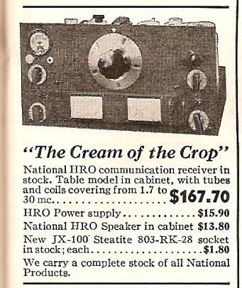
When first introduced, the receiver was the "HRO." No other designation
was necessary since it was the only version available. The receiver used
nine, 2.5vac heater tubes providing two RF amplifiers, two IF
amplifiers, separate Mixer and Local Oscillator functions, a Duplex
Diode-Pentode for AVC, Detector and First Audio Amplifier functions, a
Beat Frequency Oscillator and a pentode Audio Output Amplifier. The
separate power supply utilized a type 80 tube rectifier that actually
brought the tube total to ten.
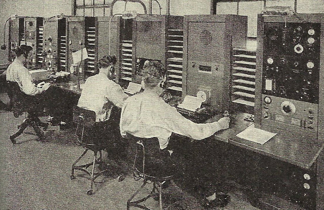
Typical of most communications receiver manufacturing,
progressively later models will have several minor improvements added as
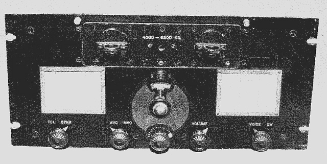
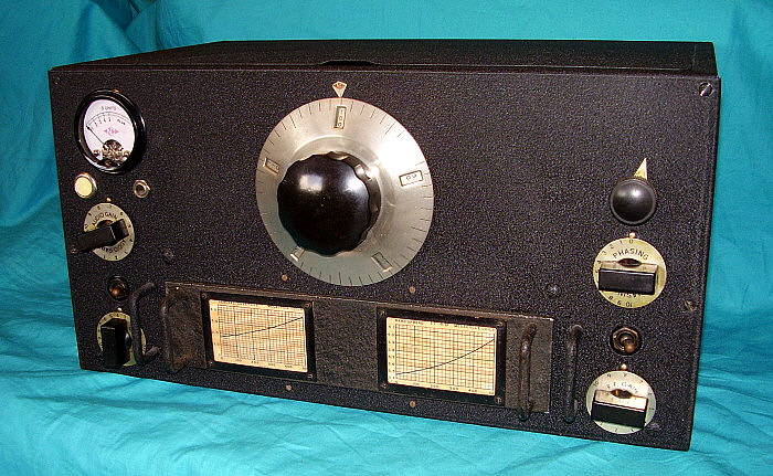
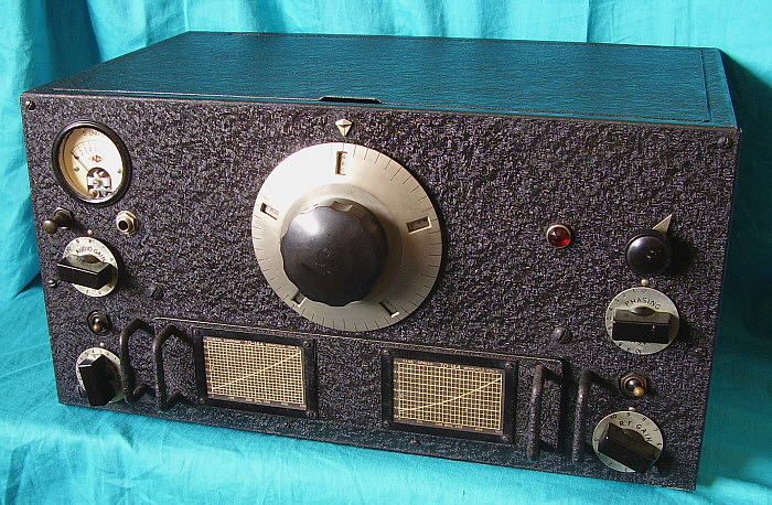
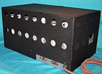
production continued. During early production both the rack mounted
versions with 3/16" thick aluminum panels (finished in a textured
"crackle finish" that resembled leatherette) were produced along with
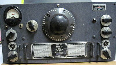
the steel sheet metal table model (painted with standard wrinkle
finish.)
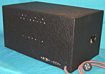
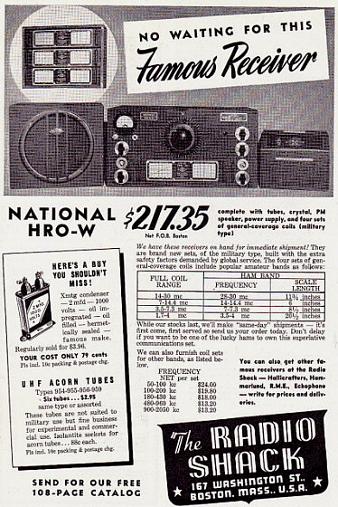
A specific power supply wasn't available for the early HRO receivers, so many
receivers were sold with the FB-7 power supply, type 5897AB
with the data plate emblazoned "Designed Especially for the FB-7."
Many rack mounted power supplies were also produced for the commercial
users. Speakers were not specifically available in a table cabinet but
National advertising stated that a "loud speaker could be provided, if
desired." The first advertised speaker shown was a rack mount version.
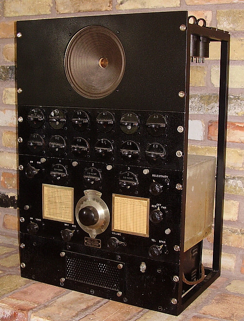
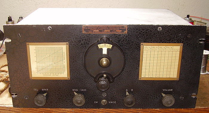
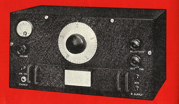
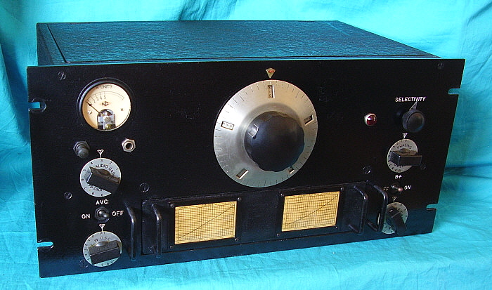
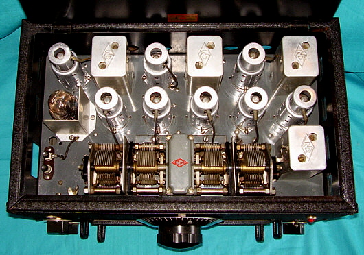
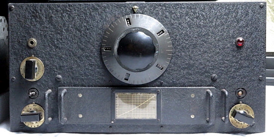
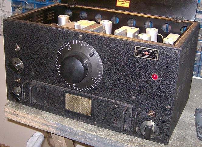
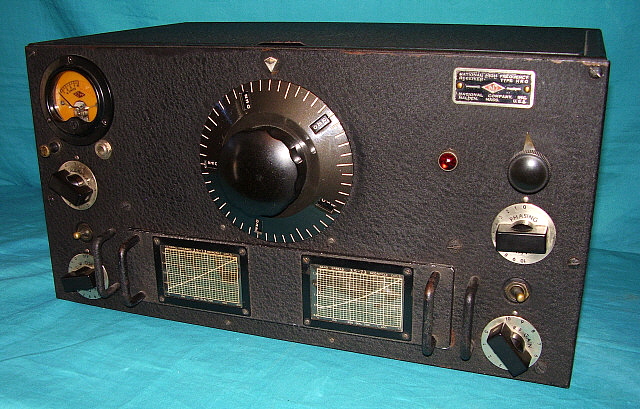
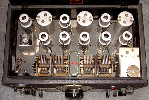
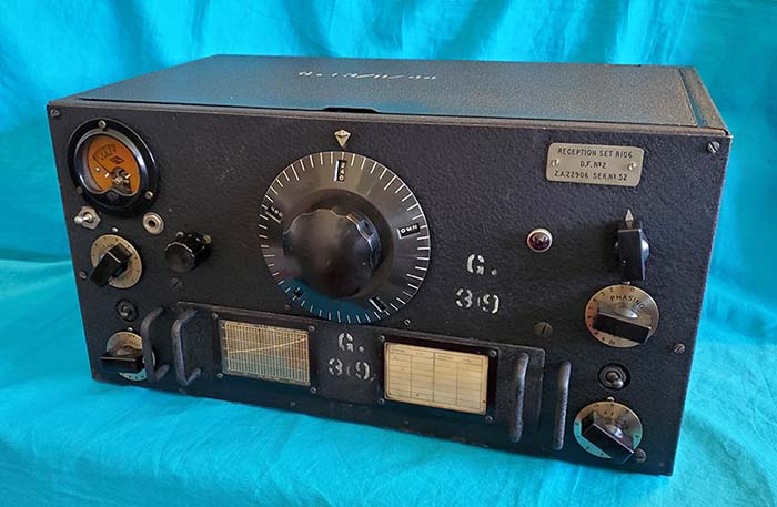
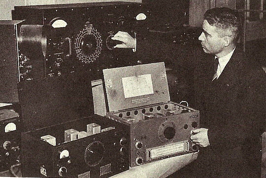
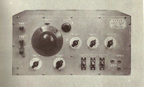
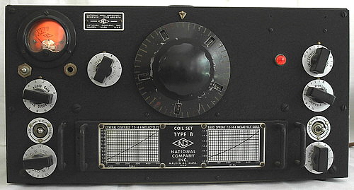
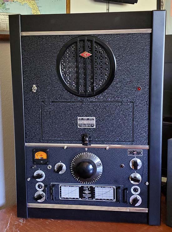
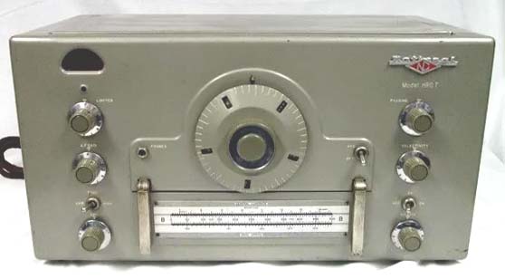
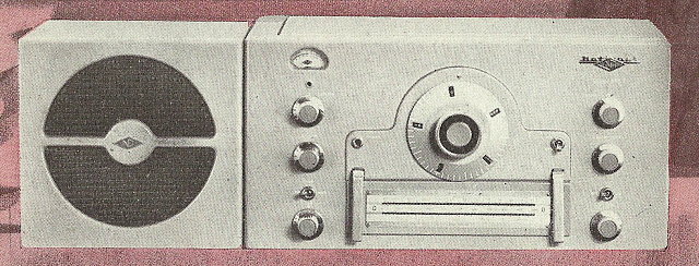
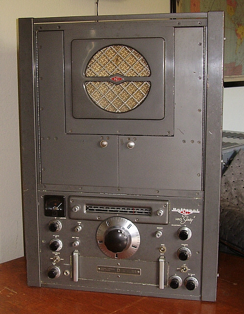
Shown in the photo to the right is a rack mount HRO from the first
production run with the serial number of D-65 with its matching serial
number coil set. Note that this receiver has all of the features that
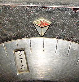
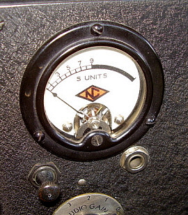
are found on the earliest production. D-65 has the pearl-button push
switch for the S-meter and the small red "NC" dial pointer mounting
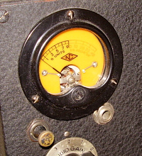
screw. Also obvious are the white background frequency charts on the
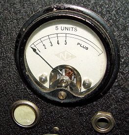
coil sets. The S-meter has the first type scale used with the pink colored
NC diamond with white letters. The S-meter scale is 0-5 with "PLUS"
indicated in the range over 5. This S-meter scale was only used on the
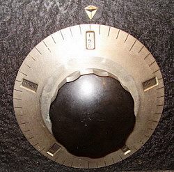
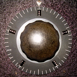
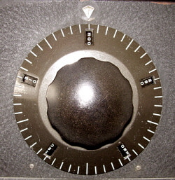
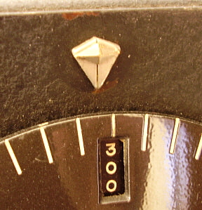
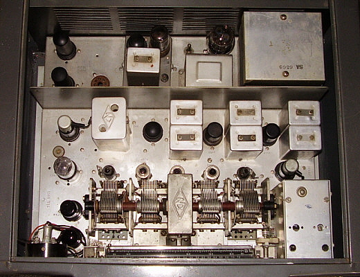
first two production runs. The German Silver plated micrometer dial was
used on the first five production runs. Notable is the leatherette
finish on the panel and on the coil set panels (this finish was used on
the rack mount receivers up until around 1940.) The four coil sets are
matching serial number originals. Also, note the lack of a finger lift
projection on the lid of the dust cover which was standard for rack
mount receivers. This receiver was probably built around January of 1935.
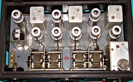
Close examination of the HRO D-65 revealed that it must have been
sent back to National for upgrading, probably around late-1936 or
early-1937. The upgrades included a pilot lamp installation, BSW
terminal strip for remote standby (included lengthening of the chassis
opening and dust cover cut-out as part of the installation,) a set of
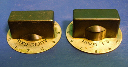
new knobs for RF Gain, AF Gain, Phasing and C.W. Osc (knobs have the
tall boss) and circuit upgrade to the 2B7 Detector, AVC and 1st AF
amplifier to conform to the later model HRO. Since the S-meter and pearl
button switch weren't changed, the receiver wasn't sent back to National
so late as to have these problem-prone parts replaced. All of the rework
is factory quality which suggests that D-65 was returned to National for
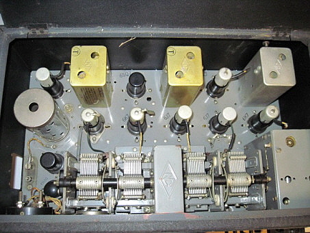
the upgrades. Note that the pilot lamp has been removed and the hole
filled to make this first production run receiver appear more like an
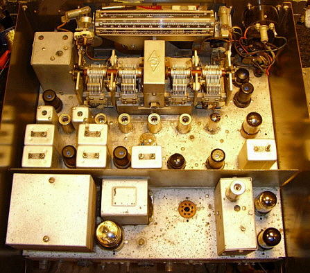
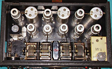
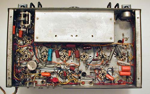
original example. The top of the chassis is still very original and the
underside of the chassis has some replacement components that suggest
normal repairs and not any type of rebuilding effort. Fifteen of the
paper wax capacitors are still original Micamold brand. |
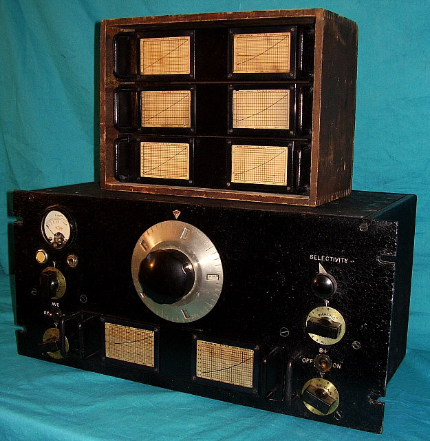
photo above: HRO sn: D-65 (rack mount,) first production run built
in January 1935
|
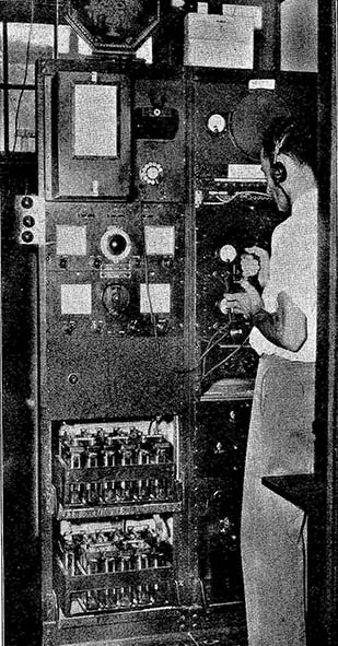
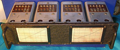

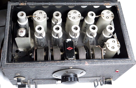
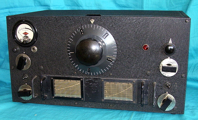
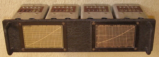
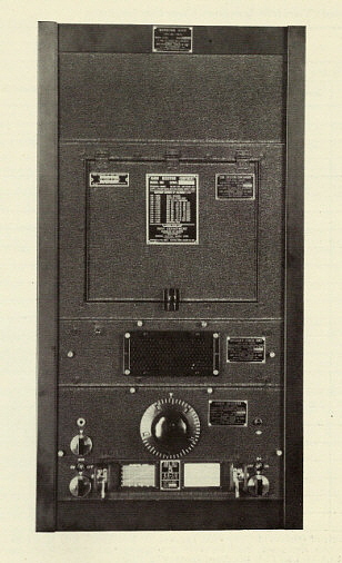

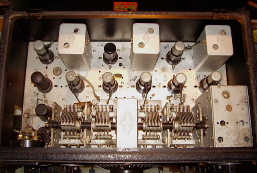

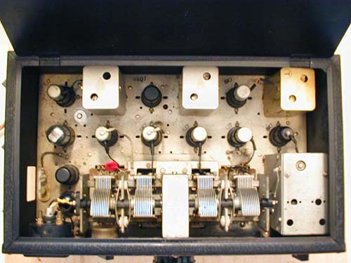
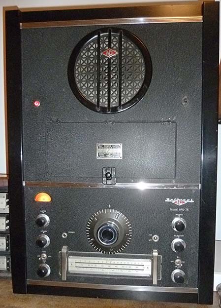


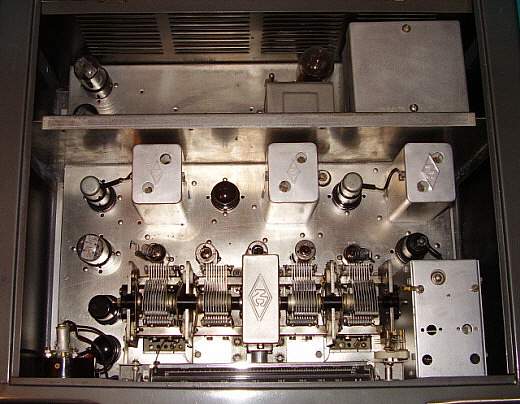
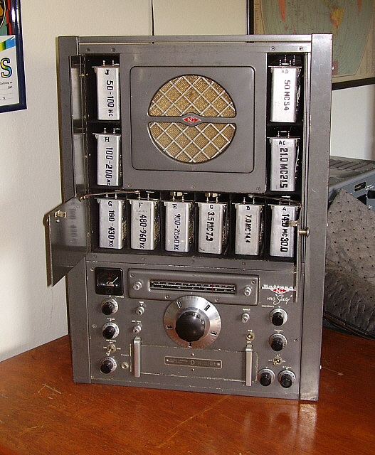 The HRO-60C Deluxe
- SN: 393 0255 - with the SC-2 doors open showing the ten coil
bays.
The HRO-60C Deluxe
- SN: 393 0255 - with the SC-2 doors open showing the ten coil
bays.