|
Detailed Inspection Turns up
Several Modifications - Apr 9, 2024 -
Although I thought the chassis was pretty much original, I've found
several modifications to the circuit. These were essentially minor and at
a casual glance might even go unnoticed. Detailed examination is
normally required to discover
all deviations from original. It's possible that some of the modifications were due to a
failed AVC switch but the other mods were attempts to stop BFO drift or
improve SSB demodulation. Eliminating the standby function might have been prompted by a
failure of the original B+
switch. Here are descriptions of the circuit deviations from
original,... Modification repair or removal description will be in
italics,...
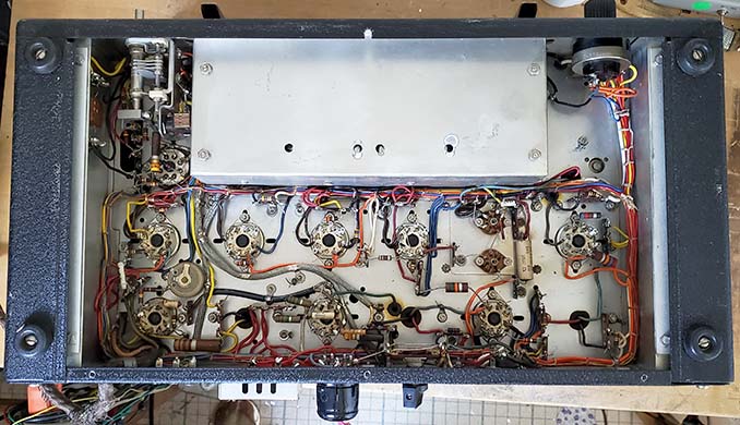
1. The IF cable that runs from
the Accessory socket (pin 4) to the 2nd IF plate connection (tube socket
pin 3) was disconnected on both ends and another shielded cable was
added that connected pin 4 on the Accessory socket to a small mica
capacitor that was connected to the 2nd IF amp grid at the tube's grid
cap. Reason was probably for an external BFO but that's just a guess.
Injecting the BFO at the input of the last IF amplifier stage will
provide amplification of that BFO level plus the signal resulting in a much stronger
heterodyne plus signal combination at the detector. This was probably installed to improve SSB
reception.
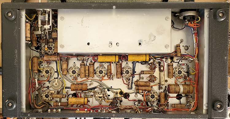
Removed the added shielded cable and capacitor. Then the original
shielded cable was reconnected to the Accessory socket and the 2nd IF
plate, as original.
2. Modification to the BFO
plate voltage utilizing pin 6 on the 6J7 socket (unused pin) to route the
regulated +150vdc for the BFO plate. Since the BFO operates at around
456kc and, in the late-forties the BFO was primarily for CW, National design engineers thought that it's stability wasn't as critical as the LO
stability. Besides, regulating the plate voltage on the BFO won't keep
it from drifting during warm-up. The VR tube was to keep the LO stable
with variations in the AC line voltage that then resulted in the B+
changing. The AC line variations could come from household appliances
turning on and off or any fairly large current demand switching on the
local AC power line. The VR tube kept the LO plate voltage constant and improved
stability but it didn't compensate for thermal frequency drift. At the time, most operators knew the HROs required about 30 minutes to thermally stabilize and that any drift
was much more noticeable when in the "band spread" set up. It
seems likely that this mod was incorporated first and found to not work
and then mod #1 was installed. In both cases, the probable motivation
was to improve reception of SSB signals.
All of the original components were still present so return to original
just involved reconnecting the circuit back to original and soldering as
needed.
3. Modification of the 6V6 screen.
It had been
wired to pin 5 of the Speaker socket as original but then also wired to the regulated
+150vdc. This reduces the available power from the 6V6 audio output
tube by reducing the Screen voltage by 33%. It might have been an attempt to reduce audio distortion although the
receiver is for communications not listening to the AM-BC band.
Originally, pin 5 was "jumped to" pin 4 B+ on the speaker plug only
and that required using an original National MCR speaker or at least knowing
what the design intent was.
All of the original wiring was present so return to original just
involved rewiring Speaker socket back to the original configuration.
4. The AVC line had two wires
missing and two small gauge
wires were added to replace the missing wires (original wires damaged?)
The new wires were then routed around the chassis differently than original. The AVC line
main junction to the switch was a cold solder joint. I think this mod
was related to a failure of the AVC switch that ended up doing much more
damage than just replacing the bad switch would have. Non-original
wires removed and authentic wiring installed and routed as the original
wiring had been. Correct color insulation wire was used for replacement
wires. Correct type of switch was wired in using correct type wire and
correct color insulation. Solder joint problems fixed.
5.
As mentioned the B+ switch had no wires connected to it and it wasn't an
original switch either. I thought the B+ wires that had gone to the
switch were spliced
together but they were just "cut" and unconnected inside a shrink tubing insulation. This
then had the receiver relying on the shorted BSW terminals to route B+ through the
receiver. Since the B+ switch isn't the original type and neither is the AVC
switch, I salvaged a pair of correct type toggle switches from a "parts set"
NC-183D from about the same time period as this HRO-7. I'm not sure why the
standby function (B+ on-off switch) on the front panel was eliminated (see #7.) The reason for the
front panel B+ switch was to allow the coil sets to be changed with the
B+ turned off. Correct type of switch installed for B+ switch.
Original wires used for the connection. Towards the end of WWII, the new HRO-5 receivers had changed the BSW switch from
being wired in series with the B+ switch to being wired in parallel with
the B+ switch. While this eliminated the need to install a jumper across
the BSW terminals for receiver-only operation, it also made the B+ switch
operation dependent on the remote T-R relay's auxiliary contact
position. Normal T-R set-up would have the aux contacts closed during
receive and that would disable the B+ switch for front panel turning off
the B+ for coil set changing. This "parallel connection" of the BSW
terminals with the B+ switch was used in HROs from 1945 up to 1949. By the HRO-50, the BSW was changed to
three terminals that allowed the user to select how the T-R auxiliary
contacts would operate the receiver B+. National's intent on this
1945-49 BSW change was probably due to set-up problems during WWII with
operators that didn't bother to read the manual so they didn't know that
the BSW terminals had to be "jumped" in order for the receiver to
operate in a "receive-only" surveillance station.
6. Plastic tie-wraps were installed
on the wire harness from the AVC junction to the RF Gain control and B+
switch. I removed the plastic tie-wraps and installed waxed-string
lacing as original. 7. The
B+ was incorrectly wired (from the mods, no doubt) and that's probably
the reason the B+ on/off switch was disconnected and B+ leads to the
switch were cut. Five different B+ wires were involved. The B+ from the
power cable should have been connected to the BSW terminal 1 along with one wire to
the B+ switch. Then on BSW terminal #2 B+ should have been
connected to the main B+ junction
wire along with the wire to pin 4 of the loudspeaker socket. Then
loudspeaker socket pin 4 should have had a wire connected to the B+ junction to
the VR tube load resistor. I unsoldered all five of the B+ wires
involved and confirmed their origin-connection in the circuit using a "ohm meter." Then each wire was soldered to the correct
destination-location in the receiver circuit. Apparently, while
installing these modifications, the perpetrator mixed up the five B+
wires and rather than "straighten out" the mistake, the perp just cut
some wires and jumped others to complete the B+ circuit. Of course, the
B+ switch no longer functioned and an original loudspeaker couldn't be
used,...but that's typically how hamster mods are executed anyway. After
straightening out the B+ wiring problem I thought I had better confirm
that the receiver would be operational. I measured the DCR on the B+ line and it was
about 30K ohms so no hard shorts. Using a spare 697 power supply, I powered up the HRO-7 on all original
parts, untested tubes,...I know,...everything that you shouldn't do,...I had coil set F
installed and a ten foot wire "test antenna." After the
receiver warmed up, I tuned in several AM-BC stations. The receiver
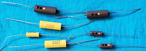
basically functions now but an alignment is necessary and definitely the
paper capacitors need replacement. Also, this
was just the chassis and the speaker was connected with clip-leads, so
just a "quickie test" to see if the HRO-7T was now successfully "de-mod'd"
and back to a "functional-original."
8. I had wondered why the
S-meter scale was so dark (it seemed much darker than usual) and when I pulled the
meter lamp I found it was a #46, the screw-base equivalent of a
bayonet-base #44, so that resulted in
a .25A lamp right next to the meter scale (I guess I was lucky it didn't
burn a hole in the scale.) I should have a good condition original scale
that I can use as a replacement. I installed a #40 lamp which is the
screw-base equivalent of a #47 drawing
155mA. Checked the spare meters that I have and all are WWII or earlier
style Marion Electric meters. These earlier meters are subtly different than the
1946 and later meters in that the font used on the later meters for the numerals and
lettering was changed to a smaller and finer type of font. Also, on the
later meters the
location of "S UNITS" and "DB OVER S-9" are over the scale rather than
under the scale. The differences are very apparent, IF it's pointed out.
So, I'll have to just leave this scale as-is, until a later style meter,
with a good scale, turns up. Luckily, almost all National receivers made
from 1946 up to about 1950 used this type of meter so it shouldn't be too hard to find
one with a decent scale. Actually, after I cleaned up the meter, the
scale doesn't look too badly darkened and when illuminated it appears
like a typical HRO S-meter.
NOTE: After about one week of fairly regular operation,
about 30 minutes to an hour per day, the "new" meter lamp failed. These
aren't vintage lamps but new ones made outside the USA. I've installed
another one out of the same package. If it fails quickly I'll replace it
with a vintage USA-made #40 lamp.
9.
Although it's not a mod, the "nati<NC>onal
" emblem does have a lot of pitting and a lot of discoloration.
There are two types of this emblem. One has posts and is mounted with
push-on clips. The second type has bend-over tabs. I found the correct
type (posts and push-on clips) on an old HFS "parts set." It was an easy
transfer. The replacement emblem, while not perfect, is in considerably better
condition and is very a good match to the condition of the cabinet. |