Radio Boulevard
Western Historic Radio Museum
 

Rebuilding the ART-13 Transmitters

Part 4


Refurbishing a Navy ATC that was MWO'd into a T-47/ART-13 (by SAAMA)

Operating the ART-13A on a Dynamotor

Using the ART-13 on the Ham Bands Today

Operating the ART-13A with the CU-32 LF Loading Coil on 630M CW


by: Henry Rogers WA7YBS/WHRM


Navy ATC with MWOs Converting it to a T-47/ART-13

Rebuilding a SAAMA Survivor

It's been a little over five years since the last ART-13 project, so it's about time for another one. I had to spend double the money for this one compared to the price of the Wasp's Nest ART-13A.


photo above: The ATC MWO'd to T-47/ART-13 SN:1887 in "as acquired" condition. Most noticeable is the slopped-on pink paint. Obviously not spilled, this looks like something kids would do with left-over house paint. It turned out that it was easily removed with isopropyl alcohol. Note on the lid lip just above the TEST switch a "notch" has been cut out of the aluminum. The left grab handle is actually broken. The left-side "crunch" isn't visible from this angle.

Feb 10, 2021 - I first saw this transmitter around October 2019. It was at the very bottom of a six foot tall "stack" of radio and test equipment. Nobody at the time wanted to move any of the equipment out of the stack to access something that was at the very bottom since there really wasn't any room in the storage area to put anything moved off of the pile anyway. A little over a year later and there had been a lot of cleaning up. There was no more "stack" of gear,...well, only a Hallicrafters HT-37 was setting on top of this ART-13 then. A quick examination revealed that this transmitter was (or had been) a Navy ATC version. The condition looked mostly complete but in need of some serious body work at the very least. I can't complain since the price was only $20. The photo to the left shows the ATC "as found."
 

Inspection, a Quick Check Out - Feb 11 - A couple of "quick tests" can determine if an ART-13 is going to be somewhat easy to get operational,...or, if it's really more of a "parts set." Inside the ATC didn't look too bad. Fairly clean and all tubes installed except the 813. The 6SL7 on the IFC/MCW module was broken but all the remaining tubes were intact. The Sperti vacuum switch on the sending relay was broken. I checked over the rotary switches on the severely bent panel and they weren't broken and did switch positions easily. The EMISSION switch was stuck but it didn't seem to be broken or bent (but a later close examination revealed that it was broken.) Amazingly the Antenna Current meter wasn't broken even though the "crunch" was just to the left of the meter. The two meters don't match but that's common on ART-13 transmitters that have been through repair depots. I tested the Modulation Transformer and it was okay. The multimeter also seemed to test okay. A quick visual check of U7 and the pins were straight and clean. The "B" control (VFO control) has a lot of chips on the knob but all the other Autotune control knobs are in good condition.

I'll have to test the pink paint, hopefully it's water based and can be removed without damaging the original paint. Remaining checks necessary would be both internal relays K-103 and K-104. The components that will require some disassembly to check will be tested during partial disassembly. Once the components that are difficult to repair or replace are tested and hopefully found to be okay, then complete disassembly can be started. Thorough cleaning and checking will then progress along. The sheet metal, once dismounted, can then be straightened. The top lid also needs a lot of body work.

ATC MWO conversion to T-47/ART-13 - Looking inside this transmitter it was apparent that it started out as an ATC, or the earliest version of the ART-13. The ATC transmitters were built for the Navy by Collins Radio Company. The ATC versions have the Collins Modulation Transformer built for Collins by Chicago Transformer Company (metal tag on top.) Also, K-105 (LF relay) is physically a much smaller relay than used in later versions. The Antenna bell insulator is made of a dark greenish-gray ceramic material. The Control B index is a simple moveable index line. These indicators were present but other ATC parts weren't. The IFC/MWO module was the later style with three tubes. The bottom combination cover-mounting adapter was the later type. There was a lid interlock switch present (not used on early transmitters.) A look at the right side of the transmitter indicated what must have happened. All the MWOs from 1 thorough 6 had been incorporated into this ATC, essentially converting it into a T-47/ART-13. I think even the data plate was changed. The stenciled identification seems to have proceeded the tag replacement.

Further Testing and Inspection - Checked DC R of the coils on K103 and K104 and found them to be correct. Dismounted the autotune cover to inspect the drive and the modules. All looked in good condition. Removed the IFC/MCW module and removed the Audio Module. Noticed that the CARBON-DYNAMIC switch was still safety-wired in the CARBON position which usually indicates this transmitter has never been worked on by hams. Removed all vacuum tubes. Removed right side panel. Removed front right panel. Removed center panel which has resistor load attachment.


photo above: Inside the ATC MWO'd to T-47/ART-13 before any cleaning was performed. The left-side "crunch" can be seen as the most serious "crumple-type" bend but there are other bends in the panel tops at various locations.

More Minor Problems Turn Up - During further disassembly,...two of the small pointer knobs have stripped-hole set screws, probably "rounded" from someone not using a spline (Bristol) wrench. I'll try a reverse flute drill bit but, if that doesn't work, I'll cut the knobs off with a Dremel tool - I have lots of these types of knobs in the knob box. Ultimately, I did have to use the Dremel tool to remove these two knobs. REBUILD NOTE: I've found that sometimes these knob set screws actually have green Loc-tite applied. It will require both heat applied with a small tip soldering iron directly on the set screw along with penetrating oil to loosen. If the set screw has a good condition socket and the correct tool is being use and it refuses to break-loose "cold" then probably it's been put in with Loc-tite. The small soldering iron usually applies enough heat to break-down the Loc-tite.  

The EMISSION switch has a cracked rotor shaft spacer for the rear switch section which causes misalignment of the rotor and that's why the switch seems stuck. This will require replacement of the switch - luckily, the "parts set" ART-13 has a good EMISSION switch. Though it's not a problem,...some desoldering is going to be necessary to totally strip the right upper (meter) panel so it can be straightened. Desoldering connections is also necessary to dismount the Antenna panel. One 12 gauge solid buss wire that will require the 250W Weller to desolder. The other connections have set screws or are mounted with nuts and lock washers. Not difficult work, but it's necessary to have the metal panels on a flat surface for proper straightening that won't "pop" the paint off.


photo left: MWOs are indicated with "M" followed by a number. These stenciled and painted IDs indicate six MWOs plus MFP coating.

Feb 19 - Body Work - Desoldered the five wires that connect to the meter resistors on the side of the meter panel. This was the last unit to dismount to totally strip the meter panel of parts for straightening. I used wooden blocks, a vise, a pair of vise grips, several aluminum and some steel blocks of different sizes and a two pound body hammer. I was able to remove the "crunch" bend in the upper corner which was the most difficult damage to repair.

The Antenna panel was stripped of parts and it also required the same assortment of body working tools to straighten its damage. The clip for the D-zus fastener needed to have the rivet mounting redone. This panel wasn't as badly bent as the Meter panel. Some paint loss in this process but nothing that can't be easily "touched up."

The right side upper panel with the tuning chart had what looked like a minor "crumple" but this bend was impossible to straighten out completely. Additionally, the aluminum had an actual "torn" hole where the lower part of the handle was mounted. I'm going to have to just replace this panel with one from a parts set. The parts set is also a converted ATC MWO'd into an ART-13, so it has the earlier style (engraved) chart panel.

The cover over the power input, remote and CU32 connectors had layers of dried masking tape on it. I soaked the masking tape with WD-40 for days and it still wouldn't come off. I'm going to have to use the cover from the parts set. The remaining panels are just slightly bent and should straighten easily.

Feb 28 - Moved the entire ATC/ART-13 project upstairs - due to the lack of bench space in the shop and the coldness of the area (the large Reznor heater is in a different room and takes an hour to warm up the shop area.) Before moving though, straightened the bottom cover and installed to protect the bottom of the chassis. Also, a minor touch-up straightening of the meter panel so the grab handle would set straight when mounted. Removed the EMISSION switch from the parts set.

Upstairs,...continued more detailed cleaning since this ATC had been in a storage unit and had picked up lots of dirt and debris. Removed the cut wire ends from the EMISSION switch and cleaned the terminals for installation. Luckily, the EMISSION switch doesn't have too many wires going to it and it only has two sections.

Used Mars Black acrylic paint to touch up areas where the paint had chipped off during the straightening process. Antenna out panel and Meter panel, so far.

Mar 1 - Continued Cleaning - Specifically cleaning in the 813-811 and modulation transformer area. Tested the "touched-up" areas on the panels by wiping with "3 n 1" oil. Wiped off excess oil with dry cotton cloth. This oil doesn't react with the acrylic paint which remains black and matches fine. NOTE: If Armor All is used, it will turn Mars Black paint somewhat brown spoiling the great match that Mars Black has for typical "aged" black wrinkle paint. The "3 n 1" oil doesn't change the Mars Black color.

Mar 2 - Continued Cleaning - Specifically the relay area under the 813-811 chassis. Cleaned Multiplier inductor area (always a dirt trap.) Cleaned variometer, antenna network switch contacts, Multiplier switch contacts. Repaired broken wire from RCVR ANT terminal to pin 7 on sending relay. Removed broken EMISSION switch and replaced with good reconditioned switch from parts set. Used black waxed cord to make harness ties (very similar to original.) Transmitter is ready to begin reassembly next.

Mar 3 - Reassembly Begins - Mounted terminals and antenna insulator to the Antenna Panel. Mounted Antenna Panel to Meter Panel. Mounted the two meters to the Meter Panel. The multimeter is from the parts set because the original meter had a severely faded scale and the flange was chipped. The Antenna Current meter is the original. It's much easier to mount the meters while the Meter Panel is devoid of most parts because access to the lower retaining nuts is difficult when the panel is fully installed onto the transmitter chassis. Mounted one of the grab handles onto the Meter Panel. It was from the parts set and replaced the original broken handle. This assembly was now ready to remount. These are the only panels (Antenna Panel and Meter Panel) that have several connections and components that have to be wired into the transmitter (the rear bottom panel has two relays mounted to it along with some cable clamps.) When mounting the switches to the Meter Panel, the placement of the harness has to be fairly low on the panel to allow enough clearance for the switch bodies.


photo right: The transmitter now has almost all of the sheet metal panels dismounted for "body work." Typical of a Collins ATC or ART-13, the chassis and most of the internal sheet metal parts are painted light gray. The very light red ink stamping to the left of the six pin Jones' receptacle are various stamps from SAAMA, the San Antonio Air Materiel Area (part of Kelly AFB.)  The conversion of this Navy ATC into an Air Force ART-13 probably happened post-WWII at SAAMA. The EMISSION switch shown is the replacement switch now installed (right-most rotary switch.) The darker gray paint splotches on the chassis are from a SAAMA "touch-up" job. At this point, the transmitter is ready to reassemble.

Mar 4 - Reconnecting the Meter Cal Resistors - Continued on with the re-installation of the Meter/Antenna Panel. Checked that the harness was clearing the switches and then installed all five switch mounting nuts (lock washers on inside of panel.) Installed mounting nuts on TS jack, TEST switch and pilot lamp housing. Installed all mounting screws and lock washers to mount panel to chassis. Pushed the five (labeled) wires through the grommet hole to connect to the meter calibration resistors, installed wires and soldered. Installed buss wire connection to LOAD COIL terminal. Disconnected RCVR wire from sending relay pin 7 so it could be routed correctly through the loop holes in the d-Zus clip. Resoldered wire to pin 7. Installed buss wire to ANT. terminal which is a solder connection.

Screw Details - Installed the domed cover over the power input connector chassis (from parts set.) Installed upper rear panel. One notices with all of the screws removed that there are two different length 6-32 screws used - 5/16" and 3/8" - that are seemly intermixed in their locations. It looks like if only one thickness of sheet metal is mounted to a tapped hole in the chassis then 5/16" is used. If two sheet metal pieces are involved, then 3/8" is used. If the sheet metal is mounted to another sheet metal piece and the threads are into a pem-nut, then 5/16" is used. All Collins-built Navy ATC/ART-13 screws are black oxide finish Philip's Head used with an internal tooth locking washer. All USAAF ART-13A transmitters used stainless steel Philip's head screws with external tooth locking washers

Installing a Sperti Vacuum Switch - If only it were as easy as installing the NOS Sperti vacuum switch into the holder and tightening the nut,...but it's not! The wire "loop" actuator inside the mount rotates slightly when going from receive to transmit. The wire "loop" rotation moves the arm inside the vacuum switch. The arm lever rod is also connected inside the vacuum switch to its external metal shell. To install correctly, first clean the metal shell where it's going to contact the inside of the mount. Sometimes there's a greenish oxidized coating that prevents good "metal to metal" contact. I used steel wool to clean the metal shell and a small wire brush to clean the inside of the mount. The arm of the vacuum switch should push down through the "loop" actuator inside the relay mount. The actuator is insulated by a glass shaft from the relay.   >>>

photo above: A close-up of the Sperti CYS-24163 Vacuum Switch showing the actuating lever that exits the bottom of the base. As shown, the left contact is NC for receive and the right contact is NO for transmit. The arm is connected to the base shell for the connection to the metal mount of the sending relay. Though the NC and NO posts are threaded, the transmitter wire connections are mounted with slide-on metal couplers that use set screws for a secure connection.
>>>   The Antenna terminal on the left side of the ART-13 connects to the mount and then to the shell of the vacuum switch. The installation should have the arm against the left contact inside the vacuum switch (goes to the Receiver terminal) with power off. If the mount clamp is tightened at this point it won't entirely keep the vacuum switch stationary. Original installations appear to have a fiber paper shim on the rear half of the mount and a metal shim on the front half of the mount. I think the paper shim was to allow for compression as the mount is tightened and the metal shim provides the actual "contact." I installed similar type shims but still had to work with the actual position of the vacuum switch as it was tightened in the mount. Sometimes the vacuum switch will move enough that the switch arm won't make contact with the transmit contact. One has to assure that as the mount is tightened, the switch doesn't move and maintains the correct mechanical position. Test with +28vdc only actuating the PTT to see that the arm does contact both "receive" and "transmit." Then apply +HV and +LV to see that the RF output does go through the switch in the "transmit" position. It takes a bit of care and adjustment to get the installation working correctly. I only had to go though this procedure because the original vacuum switch had been physically broken. 

IMPORTANT NOTE: Not only does the vacuum switch have to allow the transmitter RF to pass through the contacts without any loss but the receive position must also not present any resistance or losses to a signal from the station antenna through the vacuum switch to the RECEIVER terminal. After using this ATC for quite some time "on the air" with no problems in the transmitted signal or with any sort of loading problems, I stumbled onto an unusual problem with the RECEIVER connection through the vacuum switch. I had worked on the RBG-2 receiver on the bench where it was performing very well. When I moved the RBG-2 into position with the ATC, I noticed that the received signals didn't seem to push the Carrier Level meter quite like they did on the bench. I didn't think too much about it since the 75M signals were so strong anyway. Some months later I decided to run the AN/GRR-2 with the ATC. I spent about a week with the AN/GRR-2 on the bench working out a few minor problems and finished with a Band 5 realignment that had the AN/GRR-2 very sensitive and picking up 20M DX and the Korean Coastal Beacons on 12.6-12.9mc. When the AN/GRR-2 was connected into the station with the ATC, I noticed immediately that 20M signals were way down and I couldn't even pick up the Korean beacons. 75M seemed okay but the S-meter readings were much lower than they had been on the bench. I disconnected the ATC interconnection and ran the station antenna directly to the AN/GRR-2. The difference was amazing. 20M DX was everywhere on the band and both the Korean and the Chinese Coastal Beacons in the 12mc region were strong. Obviously, the signal loss was in the ATC and the only possible suspect was the vacuum switch or how it makes contact in its mount. I switched out the ATC and installed the Navy ART-13 with the AN/GRR-2 connected through the ART-13. The received signals remained strong. The ATC "fix" will require going over the mounting of the vacuum switch, checking the NC connection to the threaded rod and checking both receive and transmit for contact problems. More to come,...

Mar 5 - Reassembly Continues - Installed the right side cover, the tuning chart cover and the LFO blank cover. Touched up with Mars Black. Repainted right side handle with black nitrocellulose lacquer and installed after the paint had set for an hour. Also painted the left handle with the same paint so both grab handles would match. Cleaned the CFI Module and installed the shield that is on the side nearest the multiplier tubes. For some reason no shield was on this module. I had an extra unmounted shield in the ART-13 parts box. Cleaned the Audio Module and checked the value of R203 and found that 4.7K was installed which means the module had been through a depot and was upgraded. Installed the Audio Module. Mar 6 - Tubes - Tested all of the tubes that had been in the ATC. One 1625 measured enough "leakage" to indicate a "short" but it's not really a direct short inside the tube, just a leakage path that has a low enough reactance to cause the neon lamp to illuminate on the TV-7. One 12SL7GT tube was broken in the CFI module and this was replaced with a NOS KenRad tube. All other tubes tested okay. Installed a NOS Sylvania 813 tube.

With the transmitter on its rear panels, I lubricated the Auto Tune gears and worm gears with grease. I lubed the shaft bearings with 10W oil. Cleaned the contacts on the Auto Tune Forward and Rear Limit switches with DeOxit on paper pulled through the contacts. Cleaned the bottom contacts on relays K103 and K104 in the same manner. Cleaned the forward ceramic switch contacts in the Multiplier section (DeOxit and a long paint brush to apply.)

Cleaned the knobs but two needed to be replaced and the other three need touch-up on the "arrow" index. Used isopropyl alcohol and a small wire brush to remove the "pink paint" from the underside of the transmitter.

Mar 8 - Power Up and Auto Tune Test - Installed knobs in preparation of testing the Auto Tune. Connected the Dyna-Sim power supply. Turned on the +28vdc only. Turned on the transmitter at which point the Auto Tune began to run to zero (this is correct.) After reaching zero, the motor reversed and the Auto Tune then ran to the set points on Channel 3 (selected channel) at which point the four control knobs stopped and the Fine Tuning module continued to its set point and stopped and the red lamp illuminated, which is also correct. I then selected Channel 4 and the same process repeated correctly finishing at those set points. It appears that the Auto Tune is working correctly.

I tested the PTT and listened to the relays operate and watched the vacuum switch arm move to the transmit side. I then used a test lead to jump the lid interlock and turned on +LV and +HV. A dummy load and auxiliary condenser was also connected. With some "rocking" of Control C, I was able to get grid drive and plate current. The plate current did dip. Everything looked okay,...BUT,...

Looking at the watt meter there was no output power indicated. Looked at the Sperti vacuum switch and it needed some adjustment of its fit into the sending relay mount. A metal shim is necessary for good contact and a snug fit inside the mount. With the Sperti correctly fit, RF power output was present.

Mar 9 - RF Power Out - I preset all of the transmitter controls for 3970kc by looking at one of the other ART-13s around here. With this set-up, the ATC had an output of 110 watts into the dummy load. I tuned the ATC signal in on a receiver and the carrier sounded very clean. Tested VOICE mode and CW mode to see if these worked correctly and they did. Monitored VOICE in a receiver using phones and the audio was as expected when using a carbon mike (Shure 102C.) Audio Module is still wired in the CARBON position. CW note sounded good and steady.

Pink Paint Removal - Used isopropyl alcohol to remove nearly all of the pink paint. The area inside the calibration book pocket was not too accessible but still removed about 90% of the pink paint. Most of the pink paint contamination was on the top cover's edge and on the Auto Tune cover. I was able to remove 99% of the pink paint. What small amounts of pink that remained were touched-up with Mars Black acrylic. The top cover still needs body work and touch-up before it would be presentable.

Mar 10 - More Cosmetics - Dismounted the large knobs, the index back plates, the locking bars and the locking bar back plates. Soaked the knobs in hot soapy water and cleaned with a brush. The white nomenclature was already in very poor condition and this cleaning removed most of the white fill. Four of the five index back plates are usable as is. The adjustable index plate for Control B has to be repainted. All locking bar back plates need to be painted and all locking bars also need to be painted.

Mar 11 - Stuck Knob Dismount - The "parts set" ART-13A has a good condition "B" knob but someone "rounded out" the set screw sockets by either trying to drill them out or by using something other than the correct tool (spline wrench.) I've never had too much success in drilling out set screws. As usual, the reverse flute drill didn't work. Neither did the screw extractor. What I ended up doing was to drill out the hollow shaft of the "B" control (replaceable if the module is ever needed.) This got the knob dismounted. At this point a screw extractor did work on one set screw since the extreme pressure of being "torqued" against the shaft was relieved. I was able to use a "custom-made" tool and grip the remaining set screw to remove it. These were immoveable when at full torque against the shaft but could be extracted fairly easily with the shaft removed. This knob was then cleaned so it could reconditioned.

Now I could proceed with doing the nomenclature fill on the control knobs. As usual, I didn't use "pure" white as that is way too bright. I mixed acrylic for a manila color which looks like good "aged" white on black bakelite. I did the paint fill as I've described in other ART-13 rebuilds in this article.

Mar 12 - Knob Completion - Used the manila paint to do the fill on all large control knobs. Also did the same for the index lines on the small knobs. Four index plates were cleaned but two needed to have their index lines redone. These four were then installed (A, C, D and E.) B index plate needs to be repainted along with the locking bars and the locking bar backing plates. All knobs except B were synchronized and installed. Small dial on B control cleaned and installed. The B control index adjustment knob is the aluminum (older) version. It needs to be painted black.

Mar 13 - Backing Plate Painting - I use black nitrocellulose lacquer for this type of painting. I can mix up a small amount with the correct proportion of thinner and then spray using the small PreVal type of sprayer. Lacquer dries almost immediately so installation can be started without too much delay,...I usually wait about 30 minutes. Five backing plates were painted. Five locking bars were painted. The B control vernier-index plate was painted. Small B control knob painted by "dipping" to assure an even finish.

Mar 14 - Control Knob Assembly - Reinstalled the B control vernier-index plate. Installed the tension spring assembly and then installed the B knob. All locking bar backing plates were installed. All locking bar threads were cleaned and very lightly lubricated with a dab of grease and then installed. Small B control vernier knob installed. All of the controls were now refurbished and reinstalled. Next the Auto Tune cover was installed. All screws were installed with internal tooth locking washers with the screw heads painted flat black. Bottom plate was cleaned and I hadn't noticed that it had so much pink paint on it. Luckily, the pink paint came off very easily since the bottom plate is unfinished aluminum. After the cleaning, the bottom plate was installed. This completed the ATC except for the top lid refurbishment.

Mar 15 - Lid Body Work - Unfortunately the lid of this ATC has taken the brunt of the poor storage abuse resulting in bent metal, splits in the corners and many deep gouges in the aluminum, not to mention more pink paint residue. But, that's not the worst of the problems. Someone in the past actually cut-out a curved section of the aluminum edge located right over the TEST switch. There's no way to fix this problem with just "body work." Still, I cleaned the lid and then proceeded to pound it straight again. Since it had the obvious problem of missing metal right in front, I didn't spend a lot of time on the body work, I just got it basically straight so that it would fit onto the ATC correctly.

I had to do more deep cleaning with Glass Plus and a small brass wire brush to get out all of the "ground-in grime." After cleaning I proceeded with a touch-up painting using Mars Black thinned down so it was able to spread and cover up most of the serious problems. After "touch up" the lid didn't look too bad. This particular lid has a different type of High Voltage tag. All of the ones I've seen are aluminum but this one is a celluloid tag. It appears to be vintage and could be either original or a tag that was added when the transmitter was still in active use. Even with its problems, I'll keep the original lid (if it is the "original" - one never knows on these transmitters that have obviously logged lots of hours and have made several trips through the depot not to mention being worked on by SAAMA.)

Completion - I added a fixed 185pf 10KV ceramic for the Auxiliary Condenser. This C is only required on 80 meters when operating into a dipole antenna. It changes the matching network into a Pi-network for easier loading of low impedances. I think that the 185pf is just a little too high of a value of C for the voltage levels I'm using. So I've ordered a 150pf 3500vdc door knob C to take its place (when it arrives, I'll post an additional note on how it works.) Actually, the original CU-24 at 75pf would probably work best, IF I had one. I tried the 150pf capacitor and it provides 110 watts output with the plate current at "120" and the E control at "200." 150pf is actually a bit more C than necessary, replaced with 100pf.

The ATC wouldn't function correctly with the lid on due to the left side of the lid not setting down all the way onto the interlock. Adjusted the interlock switch plunger for a higher position. Also, the d-Zus fastener wire loop wasn't in the correct position because one of the rivet mounts was broken. I removed the broken rivet and replaced it with a 4-40 screw and nut. Then I adjusted the loop for the correct position. This then had the left side d-Zus fastener screw actually "click" to the lock-in position. This had the left side of the lid being held down to its proper position and now the interlock switch is closed when the lid is "locked down." The ATC is  now ready for an "on the air" test.

Mar 17 - Shake Down - I checked the audio, this time using a D-104/TUG-8 microphone with the MICROPHONE switch in DYNAMIC. The transmitter was still connected to the dummy load. I listened on the Siemens E311 (my lab receiver) using phones. Audio sounded good. Carrier was very clean with no modulation. The ATC was transferred to the ham shack and connected to the vacuum tube AC power supply. This supply provides almost the same levels of DC voltage as the Dyna-Sim. The antenna is a 135' center-fed tuned dipole with a Johnson 1KW Matchbox for impedance matching. Power output with the 185pf aux. C was 120 watts on 3974kc. I contacted KØDWC via the 'phone for a sked for an "on the air" check. The report was "sounds excellent." So, the ATC is ready for its debut on the weekend military nets.

Mar 20 and 21 - On the Air - The ATC made its "maiden voyage" this weekend, operating on the MRCG net on Saturday and on the Vintage Military Radio Net on Sunday, where I operated as net control. The ATC performed reliably and reports were all positive regarding signal strength and audio quality.


photo above
: The refurbished ATC (nicknamed "SAAMA Survivor") on top of the "Hommage a le Valve" AC power supply. It may not be the best looking ATC around but the ham operator at the receiving end doesn't "see" the transmitter,...he only knows "how it sounds" and this ATC/T-47/ART-13 does sound very good. Luckily, most of the problems encountered were on the exterior and were mechanical or cosmetic. Internally, the EMISSION switch, the vacuum switch and the plate meter were broken and had to be replaced.


Operating the ART-13A with the DY-12 Dynamotor

To set up an ART-13 for DC operation will require finding an operational dynamotor. I was given a really "rough" looking DY-12 that had come out of a basement in Carson City. It was a DY-12 which was the correct type for the T-47/ART-13 and will work fine with the ART-13A. Though not in the greatest cosmetic condition, it was very nice inside. After a full service job, it was fully operational. I used a semi-functional (actually "use at your own risk" condition) DY-12 to harvest some parts that were needed to make this operational DY-12 look pretty nice.

A suitable cable had to be constructed for connecting the DY-12 to the ART-13A. I needed to find the DY-12 DC output connector and another U7 connector for the ART-13A.  I bought the connectors off of eBay since this was the quickest way to get them here. I had an original DC input connector.

The manual doesn't specify the length of the interconnecting cable since each installation in an airplane was probably slightly different and depended on where the dynamotor was going to be located in relation to the transmitter. I decided that six feet was probably an average length. The cable used two 12 gauge wires, two 16 gauge wires and five 18 gauge wires. Pin 10 is the +HV and I used the center conductor and insulation from a length of RG-58 coax for that wire. The ART-13 manual cable breakdown only specifies the "minimum" wire gauge, so I used the largest gauge wires that would fit into the pin sockets. The wire bundle had to be shielded and wrapped with tape. The shield was made from the braided shield harvested from RG-8 coaxial cable. I connected the shield to the connector shell which provides a chassis connection at the ART-13 and also at the DY-12.

Once the transmitter cable was complete, the DC input cable had to be built. I used two wires that were 6 gauge, eight feet long and once again the cable had to be shielded. The connector has a small pin that is connected internally to the DY-12 chassis. The shield has a drain wire that is soldered to this small pin on the DY-12 side connector. At the PP-1104-C side the other shield drain wire has a lug that is connected to the PP-1104 -28vdc terminal.

When operating the ART-13A with the DY-12, the +HV runs around +1100vdc. The resulting RF power output is 110 watts on 75M. There are two DC windings providing two outputs on the DY-12, +400vdc and +700vdc. Normally, the two DC outputs are connected in series for the +1100vdc HV. At high altitudes (>25,000ft.) a barometric switch changes the series connection to reduce the HV to only +700vdc (to prevent arcing.)

To attain full transmitter RF output, the dynamotor must run at its design speed which is achieved at a minimum of  +27.5vdc input. This is the voltage at the DY-12 input, not the voltage output of the power supply. There will be a voltage drop across the cable under load. The easiest method of determining the input voltage is to switch to BATT on the meter switch and adjust the power supply so that the BATT indication is in the upper third of the BATT scale. Alternately, a suitable point can be found inside the ART-13 and the input voltage measured. The lid will have to be off and the interlock jumped. Measure the +28vdc inside the transmitter and adjust the power supply accordingly. In my installation, the standby voltage is +28vdc and loaded voltage is +27.5vdc at the transmitter. The PP-1104C runs on 240vac input. At this input voltage the delta voltage drop between loaded and no-load is greatly reduced. With the PP-1104C running on 120vac input, the delta drop can approach 2vdc or more.

Onboard the aircraft, the typical receiver that was used with a DC operated ART-13A was the BC-348 (also operated on DC) to comprise an ARC-8 set-up. This set up would require about 6 amps for BC-348 dynamotor start-up and about 3 amps when in operation. The BC-348 would have its own power cable that would also attach to the PP-1104-C. I've run this set-up and, although the BC-348 is a great little receiver, it will usually be a challenge to get Q-5 reception due to QRM. The BC-348 has a broad bandwidth so signals would be easy to find since the WWII radio op was "suited-up" in his electrically-heated flight gear that included heavy gloves and he was trying to tune the receiver while probably being shot at. When operating the BC-348 today, adjacent frequency interference will be heard. You can "dodge" SSB QRM by either tuning 2kc or 3kc above or below the carrier frequency. The SSB station is about 2.1kc bandwidth and only one sideband. The AM signal is 6kc wide and has audio information in both sidebands. It's very easy to tune the BC-348 off frequency a few kc on the opposite sideband of the QRM and recover plenty of audio in the AM mode. This is the method I use most for "dodging" SSB QRM in the AM mode. If there's SSB QRM on both sidebands and "dodging" isn't working try switching on the Crystal Filter and zero the carrier of the received station (if you're on AM.) Sometimes the Crystal Filter will narrow the bandwidth enough to provide decent copy in this situation. Typically, the BC-348 Crystal Filter will narrow the IF bandwidth to about 1kc. Also, most Crystal Filters on BC-348s are non-functional due to either needed repair or having been misaligned. It's well worth the effort to repair and adjust the BC-348 Crystal Filter so it becomes the valuable QRM-fighting tool that it should be. 

Now, the BC-348 is an excellent receiver, but I wanted to run something different. I'm using the Collins R-648 receiver, the so-called "Airborne R-390A." The receiver is DC operated with its own onboard dynamotor. The R-648 receiver used a combination of some R-390A features and some 51J features. Two mechanical filters and a mechanical-digital frequency readout are similar to the R-390A. The "odd-even" dual tunable IF, the fixed 500kc IF and reduced number of crystals in the crystal oscillator are similar to the 51J receiver. My R-648 is a 1957 contract that is operating on its own +28vdc 10A power supply. I use a "modified for 600Z ohm" LS-3 loudspeaker. The "voice" mechanical filter is 9.4kc bandwidth which is a bit wide when there's adjacent frequency activity but "off frequency tuning" helps when QRM is too close. Also, the receiver has no standby function. I rely on the ART-13's vacuum antenna switch for isolation and reduce the GAIN control when transmitting. The very cool green tag is an original inspection tag for the NOS dynamotor that I installed in this R-648. Also, the yellow tag hanging from the ART-13A's rightside handle is an original acceptance tag (dated 1954) for this ART-13 indicating that the transmitter was "ready to use."

The ART-13A running on the DY-12 dynamotor has a typical RF output on 75 meters of 110 watts to the antenna. The antenna is two half-waves in-phase (on 75M) and uses two 135ft wires that are center-fed with 77ft of open feed line, matched with a Nye-Viking coupler. I use a fixed 280pf 10kv ceramic capacitor for the external auxiliary condenser on the ART-13 (although the photo shows a variable C auxiliary condenser connected.) To also add a bit of period flavor to the station, I operate the ART-13 using a Shure 102-C handheld carbon microphone. Between the dynamotor whine from both the DY-12 and the R-648 dynamotor, the PP-1104 cooling fan and the carbon mike, the signal reports and comments are always interesting,...even on vintage military radio nets.


photo left: Collins R-648/ARR-41 on top and the ART-13A (the Wasp's Nest ART-13A) below. Both are dynamotor operated.


Using the ART-13 on the Ham Bands Today

Microphones - The ART-13 Audio Module has a "fixed-level" gain setting that was designed to work with specific WWII vintage military microphones with the ART-13 operating at its standard voltage levels available from the dynamotor. There are a couple of carbon microphones specified and a couple of dynamic microphones also specified in the ART-13 manuals. The Shure Bros. Co. T-17 was probably the most commonly used carbon microphone by the military. Many ART-13s will be found with the CARBON/DYNAMIC switch "safety wired" to the CARBON position.

Carbon Microphones - For authenticity many ART-13 users prefer a vintage carbon microphone, such as the T-17. There are two problems that are normally encountered with vintage carbon microphones. First, the military expected the radio operator to "scream" into the microphone. After all, he was trying to talk over the aircraft noise and was probably being shot at! To reduce transmitting the ambient background noise nearly all aircraft carbon mikes are "noise cancelling" types - a design that expected the operator to "yell over the ambient noise." These types of mikes can be recognized by very few and very small mike element access holes. Usually the noise-cancelling T-17 has three very small (.060" dia.) access holes while the "ground base" T-17 has seven .125" diameter access holes. The second problem is that most vintage carbon microphones don't have a response that's even close to what they had when new. Most military WWII carbon microphones will not allow enough audio for proper modulation due to "carbon packing," "carbon fusing" or other age and use related factors.

Though the ART-13 manuals will specify a couple of carbon microphones to use with the transmitter, nearly always (if you happen to have the particular types) you'll find they don't provide enough response to fully modulate the carrier. Even NOS examples won't have sufficient response due to the "carbon packing" that happens with long storage periods - like the last 80 years spent in a box with no use. For used carbon mikes you'll have to test several examples to find an element that still has proper response and has not been ruined with excessive bias voltage (which causes the carbon particles to fuse together.) Between carbon packing and carbon fusing, it's rare to find a vintage carbon mike that still will function with enough response to fully modulate the ART-13.

You can buy replacement carbon elements but many times these are of old manufacture that just haven't been used (NOS) but they don't seem to work any better than the well-used older elements. This is probably due to the "carbon packing" storage problem. It's also possible to buy new carbon mikes that do seem to work very well because they haven't been subjected to any abuse and also the carbon particles haven't had time to pack together. Typically, you'll end up testing a lot of carbon mikes before you find an acceptable example.

IMPORTANT - if you're having Carbon Mike problems - Check the value of R203 in the Audio Module of your ART-13. The original value of this resistor was 15K, which resulted in a carbon mike bias that was adequate for the typical T-17 when it was new. It wasn't long before the value of R203 was changed to 4.7K to give a higher voltage to the mike bias and therefore better response and gain. In the ART-13B schematics, the resistor value for R203 is shown as 4.7K. In all of the earlier versions of the ART-13, the value is 15K. Some carbon mikes will work fine with R203 at 15K but most won't. If your ART-13's R203 is 15K and you're fighting low response on every carbon mike you try, change R203 to 4.7K. I've found this upgrade on about half of the Audio Modules I've inspected, so it was probably incorporated into many ART-13s as they went through the military repair facilities. I think the 4.7K value for R203 is a little low and usually results in over-modulation when using a good condition carbon mike. I usually change R203 to a 9.1K 1/2W CC resistor which seems to work well with newer carbon mike elements.   NOTE: These days there are two very good solutions to the low response carbon mike problem. First, there are surplus Chi-Comm carbon mikes that look like a Shure 102C handheld mike except painted OD. These mikes have an excellent carbon mike element that provides just about the best operating response with the ART-13 R203 at about a 10K resistor installation. Second, is the Electret mike module that is designed to fit into the T17 mike. These are available on eBay for about $30. These mikes work from the bias voltage of the transmitter mike input and are "drop-in" replacements - just connect up the two wires and it works. This module sounds similar to a very good condition carbon mike in operation. With either of these carbon mike substitutes, if R203 is much lower than about 8K you can easily over-drive the audio speech amp. For R203 use 9K to 12K for the Chi-Comm mike and use 12K to 15K for the electret module mike. These values for R203 should allow you to easily achieve 100% negative modulation with the respective mikes.

Dynamic Microphones - Many Dynamic mikes usually don't seem to fully modulate either but many times this is due to a mismatch of the impedances. Many of the vintage ham dynamic mikes were fairly Hi-Z, around 10K was common. This mismatch will result in low gain. You can use a matching transformer but that's really getting to be a hassle. Try to find a Dynamic mike that has an output impedance of 250Z ohms which is what the ART-13 is designed for. You might find that some of the newer 500Z ohm dynamic elements are also a good enough match to the input Z.

Electret Mike Elements - These mikes can work with the carbon mike bias voltage available from the transmitter. Usually some sort of solid-state output driver is necessary to vary the conductivity of the mike's output to be compatible with a carbon mike circuit. Complete "drop-in" mike modules that fit into WWII mike bodies are available. These modules work very well with most WWII transmitters that used carbon mikes. The audio quality is very good, sounding very much like a brand-new carbon mike. I've noticed that if the "spit cloth" is installed in the mike it tends to noticeably reduce the highs of the audio response but the trade-off is that breath noise and over-driving are enhanced without the cloth. Also, the body cavity of the mike should be filled with foam rubber to reduce "echoing." Sometimes the audio response is so "hot" that the mike has to be held up to 12" away from the mouth. If this is happening, try "side-talking" the mike. Also, make sure R203 is the stock 15K value when using these modules. You do have to experiment with these electret modules as they seem to perform differently with each transmitter the mike is used on and especially with different types of mike bodies that they are installed into. One should remember that the electret mike elements that are sold on eBay were designed for the T-17 mike and almost certainly for the most common version of the T-17, which is the "noise cancelling" version with the three small holes in the cup. This type of T-17 would greatly reduce the breath noise and over-driving that is common when using these elements in other mike bodies. NOTE: The builder of these electret modules has indicated that he will no longer be building or supplying them, on eBay or anywhere else - May 2021.   

An Easy Microphone Solution - The easiest method to have high output from the microphone, that allows you to easily run the ART-13 with 100% modulation, is to use a preamplifier between the mike output and the transmitter input. The Astatic TUG-8 mike stand is the easiest way to provide a preamplifier since a battery operated one is in the base of the stand. You can use any of the Astatic mike heads, e.g., 10-D, D-104, T-3, etc., and with the TUG-8 stand, these mikes will all sound fine and provide plenty of output. The preamplifier output Z is a fairly close match to the Dynamic input Z. Be sure to have the switch in DYNAMIC when using the TUG-8. Also, watch your transmitter's output waveform on an oscilloscope to set the TUG-8 "gain" control to proper level of modulation. The "gain" control is adjusted by a slotted shaft potentiometer that is accessed via a hole in the bottom cover of the TUG-8's base.

Operating AM (VOICE) - Initially, an oscilloscope must be used to determine if the microphone chosen is really a suitable one for the ART-13. The oscilloscope will almost instantly show you whether or not you are achieving 100% modulation. The easiest way to use the oscilloscope as a "modulation monitor" is to connect a "pick-up wire" to one of the vertical amplifier inputs. The length of the "pick-up wire" will be depend on your power output, location of the antenna and how much vertical amplification you use on the 'scope. Most of the time a three foot wire works fine, sometimes you might have to use a 10' wire - experiment with what gives the best 'scope pattern. While transmitting in VOICE, adjust the 'scope for a modulation envelope pattern and you will almost instantly see if you have full modulation. Just a slight "touch" at negative 100% is seen as either a slightly brighter "dot" at zero or a very short "line" at zero. Both are indications that the ART-13 is modulating to 100% negative and any increase in audio will result in "negative cut off" which can cause modulation transformer problems. Just the bright dots at negative 100% is okay and you don't want to go any further than that with your audio drive level. Note the positive excursion also. This should be symmetrical and at 100% positive. If you find that you are not achieving 100% positive but are at 100% negative modulation you might have weak 811 modulator tubes. Also, it's possible that there is some excessive current being drawn on the +HV which limits the positive peaks of modulation. You can reduce carrier power somewhat and see if that helps with the modulation symmetry. Operating CW - Many ART-13 owners don't operate the transmitter in the CW mode. This really isn't because of a lack of CW expertise but mainly because there are some limitations to "comfortable" operation in the CW mode. The ART-13, like most military transmitters, uses a Keying Relay to provide many functions inside and outside the transmitter. Outside the transmitter would be the Antenna switching and Standby function between the ART-13 and the receiver that provides "break-in" operation in CW. However, the Keying Relay is noisy - no doubt, on the airplane it was probably barely noticeable, but the typical ham shack will be a cacophony of racket when the ART-13 is transmitting CW. Also, if you're a fast CW operator, the Keying Relay will limit your speed. Although the ART-13 manual says that 30 wpm operation is possible, 15 wpm is a more realistic "speed limit." There are some modifications to eliminate the Keying Relay operation in CW and key the various circuits directly but there is NO justification to "hacking up" a WWII military transmitter just to satisfy the ham-ster need to modify stock circuits. Besides, operating the ART-13 in CW in the original configuration is authentic and provides the user with some of the experiences that the WWII airborne radio ops had to endure.
Antennae, Auxiliary Condenser and SWR - The ART-13 is not a ham transmitter, so it's not surprising that it doesn't readily operate into a dipole or quarter-wave vertical antenna. One of the idiosyncrasies of the ART-13 is that it was designed to operate into antennas found on aircraft. This was usually either a 20-60 foot end fed wire from the front of the plane to the tail, or a 200 foot long trailing wire antenna that was also end fed. Sometimes short whips were also used. Anyway, it's unlikely that any ART-13 ever originally operated into the 50 to 75 Z ohm unbalanced, low reactance (mostly resistive) type load that most ham antennas provide. The common solution is to add approximately 50pf to 100pf of capacitance from the COND terminal to the GND terminal which then provides a Pi-Network of sorts in Tuning positions 1 to 6. In positions 7 to 13, a Pi-network is already provided and usually above 7.2mc an auxiliary condenser shouldn't be required. Most amateurs operate the ART-13 in the 80-75M and this might require additional capacitance. However, adding the auxiliary condenser depends on your particular antenna and any sort of L or C reactance it has at the frequency of operation. In some cases, an auxiliary condenser won't be required because the antenna itself is providing the C necessary for a proper plate loading. Experimentation will be required if with 100pf of auxiliary C the ART-13 has too much plate loading. It does depend to a certain extent on any slight mismatch or SWR. Just a slight mismatch, depending on whether it's due to Xc or Xl, will alter the matching ability of the transmitter and auxiliary C might not be required.

If you operate on just one or two frequencies in the 75M band and you have a "perfect" match of antenna and feedline (perfect 1:1 SWR,) then a fixed value, high voltage capacitor can be used for the auxiliary C. It's also possible to provide a couple of fixed value HV capacitors to provide optimum loading on different types of 80M antennae or when operating at the extreme ends of the 80M band. Although it's possible to use a transmitting air variable capacitor which could allow optimum setting of the antenna loading and any 80M frequency, it's not recommended. Be sure to only use the minimum value of C for the aux-C that will provide the desired output power. Using a larger C value than necessary will tend to saturate the PA tube which reduces the output power, even though the PA current might seem to increase. Continually operating the ART-13 with too much aux-C will greatly reduce the life-expectancy of the 813 PA tube,...(and it's proportional to the level of +HV used.) I've found that when operating with +1100vdc +HV and loading for about 110 watts output power and using a perfect 1:1 SWR resonant dipole antenna (matched with an external antenna coupler) that about 100pf provides enough capacitance for a good match and ample power (with E control set to minimum C or 200 on knob scale.) However, the original CU-24 allowed 25pf, 50pf and 75pf to be used as the auxiliary C. I actually think that the 50pf or 75pf might actually work quite well with minor adjustments of the E control, but again, it is totally dependent on the antenna being used and how close to a perfect Z match is present at the operating frequency. As an additional note, when rebuilding my colinear array antenna, I ended up with a 1.3:1 SWR. When tuning the ART-13 up to the antenna, I found that 100pf was way too much aux C. I went to 50pf with the same results. Then I removed the aux C completely and the loading was still a little bit more than I like. The only solution was to "re-trim" the colinear array so the tuner could provide a perfect 1:1 SWR. This brought the ART-13 operation back to normal.  

SWR - Be sure when loading the ART-13 into an antenna that you use the lowest setting of C that allows tuning the transmitter to the antenna load. Although you can find higher settings of C that might appear to tune to the antenna, you might actually be tuning the transmitter to a harmonic instead. If you have an SWR bridge in the antenna line, look at the SWR and, if the antenna is matched for say 80M and you show a low SWR, then the setting of C is okay. 40M operation is very prone to tuning to a harmonic - watch your SWR and monitor your transmitting frequency.

Frequency Monitoring and Why Zero Beating Doesn't Work - The easiest way to monitor the frequency of the ART-13 is with a digital frequency counter. The Counter can have a short "pick-up" wire connected to the counter input and that should provide sufficient signal for it to operate on. Normal AM net operations are on specific frequencies so it's rather easy to set the ART-13 up before hand.

If you have to do a minor adjustment to the frequency merely unlock the locking bar on Control B and fine tune the transmitter to the correct frequency. Be sure to re-tighten the locking bar afterwards. If you have the transmitter in MANUAL you can just adjust B to the correct frequency (leaving the locking bar tight.)

If you try to use the CALIBRATE position to zero beat the ART-13 tuned frequency to a received signal, you'll find that it doesn't work. The reason is the CALIBRATE position was to allow the radio op to use the FCI module's 50kc calibrate signal and to listen on earphones in SIDETONE for a heterodyne on the nearest 50kc cal point to the desired frequency for transmit. Only the PTO is in operation and it tunes 1000kc to 1510kc (in two ranges.) CALIBRATE was never intended for zero beating a signal in the receiver.

BC-348 Receiver Operating with ART-13  - ARC-8 was the designation for one of the most common set-ups for aircraft use of the ART-13 and combined it with the popular BC-348 receiver. Today, many hams run the ARC-8 configuration as it provides an aura of authenticity to a vintage military radio station (and the BC-348 is a great performing receiver.) The BC-348 can be wired into the U-8/U socket on the ART-13 to provide full break-in operation. Use pins 23 and 24 on the ART-13 U-8/U socket to provide a NC connection to pins 3 and 4 on the PL-103 connector on the BC-348 which will allow the ART-13 to control the stand-by function. Pins 23, 24 and 25 on the U-8/U socket access the internal sending relay in the ART-13.

U-8U pin 23 - Common (arm)

U-8U pin 24 - NC

U-8U pin 25 - NO

Using the R-390A with the ART-13 - The R-390 and R-390A receivers require a NO set of contacts for receive and going to NC during transmit for proper BREAK IN operation of the receivers. You can use pin 23 (arm) and pin 25 (NO) to provide a proper "Break-in" for the R-390 or R-390A receivers.

Using the R-388 or 51J-4 with the ART-13 - The Break-In on these receivers is unusual in that a voltage must be supplied to actuate the "break-in" relay that's internal to the receiver. Break-In voltage is from +12vdc up to about +18vdc. It generally requires a small DC power supply or battery that can have its output switched using pins 23 and 25 of the U-8/U socket on the ART-13 to apply the break-in voltage to the R-388 during transmit. A "wall wart" type of DC power supply can be used although some versions are RF noisy. Be aware that the front panel STANDBY position does not operate Break-In (which isolates the receiver input during transmit.) Break-In can only be operated by applying +12vdc to the REMOTE terminals 2 and 3.

Using the REC ANT Terminal - Most of the time the easiest method for receiver antenna connection is to use the REC ANT terminal on the side of the ART-13. This routes the receiver antenna input to the vacuum antenna switch to the NC side connection. The arm of the vacuum switch connects to its base and then contacts the vacuum switch mount and that connects to the transmitter antenna terminal. At lower frequencies, there usually isn't a problem with losses in this routing but if 20M operation is being considered, you may find that noticeable signal loss will be experienced. Try a direct antenna connection to the receiver and then try going through the ART-13 for comparison. At higher frequencies, the losses will be noticeable but it's not apparent at all on 80M or 40M. Use a very short connection between the transmitter and receiver to reduce losses. Also, a separate receiver antenna might be a solution. Again, this is only noticeable on higher frequencies.

Physical Location and Shock Mounts - There are a couple of different shock mounts that were used with the ART-13 transmitters. All of them are beyond difficult to locate. Probably when the transmitters were removed from service, the shock mount was left behind and scrapped with the airplane. Today, ART-13 transmitters are rarely offered or found with an original shock mount.

When placing the transmitter in its location in the station you will have to simulate what the shock mount provided. Not the vibration dampening but the elevation of the transmitter up off of its bottom plate. This elevation was how the ART-13 cools itself - by convection. Use spacers made of wood or rubber to raise the transmitter up so there is at least one inch of clearance between the table and the bottom cover. Two inches is better. This is usually enough to allow air flow and cooling.

Loading up the ART-13 on 75 Meters - If you read the loading instructions in the ART-13 manuals you are sure to be confused since these are written for operation with aircraft antennae. Hams generally are using a dipole antenna which will tune differently. First, if you're using a resonant dipole make sure you have an auxiliary capacitor connected to the COND terminal to the GROUND terminal. This can be a fixed ceramic HV cap of around 100pf. Be sure your antenna match is a perfect 1:1 SWR.

1. Adjust Control E to 200 - minimum capacitance
2. Adjust Control D to mid-scale - around 50
3. Adjust Control C to triangle #5 (be sure the control is exactly set on the triangle)
4. Set switch to TUNE
5. Set A Control to triangle #4 and B Control to 8 on the small dial and 25 on the large dial (4.825 is approx. 3975kc)
6. Make sure your antenna is tuned to around 3975kc
7. Actuate the TEST switch
8. Use Control D to adjust Plate Current to minimum
9. Set switch to OPERATE
10. Actuate the TEST switch and see what the Plate Current is (this is total Plate Current so it is reading the 813 current plus the two 811 modulator idling current at this point.)
11. Dip the Plate Current with Control D and note the Antenna Current meter should peak at the dip.

You can only increase the loading capacitance with Control E (200 is minimum C.) This will increase the plate current in the configuration used on 80M. Normally, the value of the "fixed" Auxiliary capacitor is chosen to give some adjustability on Control E for the desired loading for the frequency and antenna used. 50pf to 100pf seems to work well most of the time (with a perfect antenna match.) When using a 100pf aux-C, adjustment of Control E won't be necessary.

NOTE: The ART-13 loading will vary somewhat depending on the level of +HV used and on the antenna being used. This description applies for +HV levels around +1100vdc. Higher or lower levels of +HV will result in slightly different resonant points for Control D. Also, higher +HV levels will also require slightly higher aux C values but you shouldn't use a value higher than 150pf (when operating into a 1:1 SWR resonant dipole antenna.) If the antenna used has some Xc (capacitive reactance,) then the aux C might not even be required. It depends on the antenna Z-match and the SWR and the type of antenna. Generally, a resonant dipole fed with coax or a tuned dipole with a perfect match will require some Aux C, usually around 100pf or maybe somewhat less, depending on the +HV level. Experiment with different antennae and different Aux C and settings of Control D.

40 Meter Operation - Operation on 40M is basically the same as 75M except that Control C will be advanced up to triangle #8 or higher. At this point, the output network is actually a  Pi-network and the auxiliary capacitor won't be required if a dipole antenna is used. Interestingly, the 40M band seems to be split with Control A referencing 7.2MC as the point of change. Usually, when operating in triangle #8 on Control A the lowest frequency tuned is about 7.15MC so you won't be able to tune into the CW portion of the band. Switch to triangle #7 on Control A for operation in the CW portion of the 40M band and you'll find that entire 40M band can be tuned. You might find that the Grid Drive Current is down a bit on 40M, since the alignment procedure allows for reduced Grid Drive at the band edges. 

Dealing with the Stacked Trimmer Capacitors in the Multiplier Section - If you plan to do an alignment of the Multiplier stages to bring the Grid Drive up then be very careful of the stacked adjustment capacitors - they are very delicate and easy to break unless the adjustment tabs are checked to see that they can be moved without difficulty. When the ART-13 was initially aligned, a "locking fluid glue" was put on these condensers so the adjustment would hold under the conditions usually found on airplanes in flight. The "breakage" usually occurs when the adjustment tab is "forced" to move against the locking fluid glue.

The first thing to try is using a heat gun to melt the locking fluid glue. Use the heat sparingly and try moving the adjustment while the trimmer is warm. The arm should easily break loose but be gentle and don't force anything.

If heat doesn't work then disassembly is the other option. The mounting screws can't be removed unless the VFO section is dismounted from the transmitter chassis. This is a very difficult procedure and not really necessary. The trimmer condenser mounting screws can be loosened and the nuts removed. This will allow the "stack" to be somewhat separated. This allows some access for lacquer thinner to be brushed on to remove the glue. Test as you clean for easy adjustment of the arm. >>


photo above:
The  delicate "Stacked Capacitors" for aligning the Multiplier Section of the ART-13. These caps have +LV on them, so be careful and use an insulated alignment tool.
 >>> When the stack is reassembled, the adjustments can then be made without breaking the condensers. When doing the alignment, be aware that there is +LV (about +400vdc) on these caps so be careful and use an insulated alignment tool.

You can actually operate the ART-13 with the Grid Drive a little below the scaled area on the meter but if you have very low Grid Drive, you'll have to align the transmitter's Multiplier Section. Most of the Multiplier Section alignment issues are on higher frequencies - generally 7.0mc and higher. Usually there is always sufficient grid drive on 75 meters.

20 Meter Operation - 20 Meter operation is similar to 40M operation. You'll find that it is very near the top frequency that the ART-13 is capable of but usually no problems will be encountered. You'll probably have to have Control C at triangle #12 for loading up to full power. It's normal for the power output to be down slightly on 20M. I can get about 100 watts output on 20M with +1100vdc +HV.

Again, if you encounter very low Grid Drive you'll probably have to align the Multiplier Section of the transmitter. Use the procedure in the manual and be patient because it is a tedious, time-consuming job.

If you experience arcing inside the transmitter on 40M or 20M but not on 80M, it's probably a loading problem. Reset the position of control C first. If that doesn't help, try reducing the loading for lower total plate current. Most arcing problems are due to mismatched antenna loads.

30 Meter CW Operation - Since the ART-13 is continuous coverage from 2.0MC up to 18.0MC, it's possible to do some CW operating on the 30M band. This is a small segment from 10.100MC up to 10.150MC available for ham operation in CW/Digital modes only. Naturally, a general coverage receiver will have to be used in conjunction with the ART-13. Since most hams are using tuned dipoles for an antenna, be aware that these normally will work fine on harmonically related frequencies but may not allow loading on 30M. I just use a separate small dipole specifically cut for 30M. Dimensions are 23 feet per leg and I feed the antenna with coax and a 1:1 balun. Be sure to check the "30M Band Plan" PDF file because each segment of the 30M band is allotted to specific functions and modes. Also, 200 watts is the maximum output power.

Operating the ART-13 on MW - 630 Meters (472kc to 479kc)

630 Meter Basic Info - This new Medium Wave band is 472kc up to 479kc,...only 7kc wide. There's an unofficial band plan that allocates CW to the lower few kcs although CW is legal for the entire 7kc. Data transmissions are supposed to be in the top few kc (but unfortunately some non-CW ops don't adhere to this band plan.) Operation is limited to 5 watts EIRP but since most antennae are so inefficient at 472kc, it could take perhaps 100 watts antenna input power or more to achieve the 5 watts EIRP. You will have to do some antenna modeling (calculations) to see the efficiency of your proposed antenna at 472kc and calculate what input power results in 5 watts EIRP. Additionally, you must submit your physical location to the Utilities Technology Commission for approval of operation on 630M. They will confirm that you are located more than 1km from the nearest power transmission line that might use controlled-carrier troubleshooting data on it. The process to submit your 630M request to the UTC is very easy with the online form that automatically is sent directly to the UTC. You have to supply the UTC with the physical location of your 630M antenna by using a GPS coordinates conversion to degrees-minutes-seconds. The UTC will contact the applicant by e-mail IF there's a problem. IF no e-mail contact is received within a six week period, then there is no problem with 630M operation at your location.

Here is the link to the UTC website and the 630M request form:  https://utc.org/plc-database-amateur-notification-process/

Equipment Required - Your ART-13 must have the plug-in LF Oscillator module installed. There are two types, the early "Navy" version with six ranges (O-16/ART-13  - 200kc up to 1500kc) and the later "USAAF" version with three ranges (O-17/ART-13A  -  200kc up to 600kc.) Both types tune 630 meters (472-479kc.) However, the O-16 USN version "splits" the 630 meter band as it has a range change at 475kc. There is enough "overlap" to allow tuning the entire 630 meter band at either the band edge selected.

Once you have the LFO module, then you'll notice (when looking at the ART-13 schematic) that there's no RF output antenna coupling stage for LF inside the ART-13. The LF output from the PA is coupled through the plate blocking capacitor directly to the terminal marked "LOADING COIL" (J-117.) Onboard the airplane, an "ANTENNA LOADING COIL" (antenna tuner) was installed if LF operation was going to be required. CU-32/ART-13A Antenna Loading Coil was the largest version with the most elaborate circuits and it was built specifically for the USAAF. It allowed tuning the normal type of aircraft antennae for operation with the ART-13 operating from 200kc up to 600kc and included a RF amp meter. There was also the smaller USN CU-25 that used a much simpler circuit but still allowed tuning from 200kc up to 600kc. There was also the small USN CU-26 that was used for tuning 500kc up to 1500kc. The CU-32 allowed switching from either a trailing wire or a fixed antenna. The CU-25 and CU-26 were for trailing wire only. The CU-32 is shown in the photo to the right on top of the ART-13. It should be noted that the CU-32 is about the same size as the ART-13. However, it does weigh considerably less than the ART-13 (note the photo below to see why the CU-32 is a "light weight.")


photo above: ART-13A with O-17/ART-13A LFO installed with CU-32 Antenna Loading Coil on top.

LF Tuner Details - Of course, the upshot is that you can't operate the ART-13 on 630M without some type of antenna tuner. It doesn't necessarily have to be the CU-32 or the CU-25. A homebrew tuner could provide the impedance matching. If you're considering using the CU-32 or CU-25 Antenna Loading Coils, remember that these tuners were specifically designed to work with the antennae that are found on WWII aircraft. That would be the Trailing Wire Antenna, a variable length (up to 200') stainless steel stranded wire with a "winged" weight on the end (so the antenna wire would fly straight and directly behind the aircraft) that was reeled out the tail of the airplane while in flight. The Trailing Wire Antenna is essentially an end fed wire using the aircraft frame and fuselage as a counterpoise. The "Fixed Antenna" was generally a very short antenna that ran from the cockpit to the tail of the airplane and was "off-center" fed. These tended to load like a short vertical antenna. Fixed Antenna could also have been a short whip of some type (only the CU-32 matches the "fixed antenna.") Whether the CU-32 can match a typical ham vertical is unknown. Only experimentation would provide the answer. The Trailing Wire output will work with an end-fed wire that is at least 100 feet in length worked against ground. Longer wires are much easier to match. The majority of circuitry in the elaborate CU-32 is switching to allow both LF tuning and routing HF from the ART-13 through the tuner to the selected antenna in use. The CU-32 allows all connections between the ART-13, BC-348 and the CU-32 to remain attached and controlled by the ART-13 PTT line and selection of LF operation. The actual CU-32 "tuner" circuit is a simple LC network with fixed-C values and a variable L (variometer with loading coils.)
How the CU-32/ART-13A Antenna Loading Coil Works - When in LF, the ART-13 PA output is at LOADING COIL terminal. On the input side of the CU-32 is the "LF" terminal which is connected by a wire or cable to LOADING COIL terminal on the ART-13. CU-32 "HF" is connected to the ART-13 HF RF output using a wire or cable. When the ART-13 is not in "LF" the CU-32 is bypassed by having the vacuum switch and relay actuation voltage removed so the CU-32 always stays in "HF" if the ART-13 PTT line is actuated. When not in "LF," the ART-13 HF RF passes thru to the selected antenna connections on the side of the CU-32. TRAILING or FIXED can be selected and this selection ability is always active and applies to either LF or HF.

When "LF" is selected on the ART-13, then the RF output from ART-13 LOADING COIL terminal to CU-32 LF input is routed into the tuner circuit (via K-105 in the ART-13.) The CU-32 RF Amp meter is on the input side with series dropping resistors to chassis. Two parallel fixed-capacitors are from "LF" input to chassis. The "LF" input also connects to the loading coil/variometer. Taps are selected via the FINE LOADING. The variometer is used for PA PLATE TUNING. COARSE LOADING selects taps from the bank-wound coil under the Antenna switch. LF RF output is connected to the NO contact of the vacuum switch. "HF" input is connected to the NC contact of the vacuum switch. The arm of the vacuum switch is connected to the antenna switch that selects TRAILING or FIXED antennae. Actuation of the ART-13 PTT (key down) operates the ART-13 and the CU-32 vacuum switch which places the LF RF onto the particular antenna selected. The receiver is placed in standby via the ART-13 keying relay and the receiver antenna input is isolated by the CU-32 vacuum switch and by the vacuum T-R switch in the ART-13.

Rebuilding the CU-32/ART-13A - It seems that CU-32s are commonly found with a lot of internal damage. This is because several of the components and mounts are really somewhat delicate. It was never expected that the CU-32 was going to be dropped, thrown to the ground, slammed against other equipment and generally treated like it was a typical indestructible piece of military equipment. My CU-32 had the ceramic coil mounts on L2502 broken. On the variometer coil (L2501,) the coil form itself was broken in several places. The switch S2502 had several broken ceramic pieces. Luckily, the vacuum switch wasn't broken but the long ceramic stand-off mount was. Repairs consisted of disassembly to remove the damaged parts followed by lots and lots of epoxy repairs. If carefully done, the epoxy repairs are almost invisible and can become strong bonds if done correctly. The results of the internal repairs can be seen in the photo to the right. The repairwork is almost invisible and the CU-32 functions as it should.

photo above: Inside the CU-32 ANTENNA LOADING COIL showing the various components. The ART-13 inputs are to the right while the antenna connections are to the left. The vacuum switch and relay actuator is center-rear on the chassis (K-2501.) The relay is inside the metal housing. The fiber rod protruding out the top actuates the vacuum switch. This vacuum switch and actuation relay follows the keying of the ART-13 in CW giving the operator full break-in operation. The vacuum switch and relay operates on the PTT line and switches the CU-32 from "LF Input on transmit" to "HF Input on receive." Note the two spark gaps that are painted red. The one by the Antenna output is easy to spot. There other one is at the front of switch S2501. These are on the Fixed Antenna section to protect against arcing that is common with "short" antennae. Voice can't be used on LF with a Fixed antenna because of possible arcing.
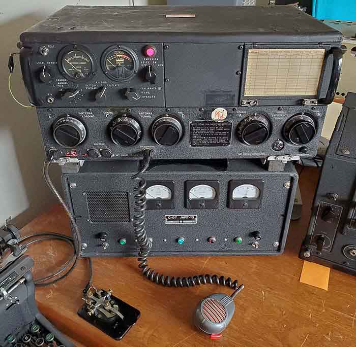
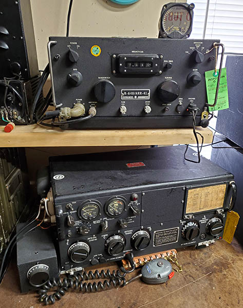
BC-348 Operation on LF with the CU-32 Loading Coil Tuner - The BC-348 was always connected to the ART-13's RECEIVER (J110) terminal. With LF selected on the ART-13, the vacuum switch inside the CU-32 toggles back to "HF" when the PTT line is deactivated (key up) and that then allows the BC-348 to connect to the aircraft antenna via the ART-13's "HF" routing through the CU-32. When PTT is actuated (key down,) the CU-32 vacuum switch toggles to LF which connects the ART-13 J-117 terminal to the CU-32 LF input. The ART-13 output is routed through the CU-32 to the selected aircraft antenna. The BC-348 is further isolated during "key down" via the ART-13's vacuum T-R switch. With PTT deactivated (key up,) the ART-13 and CU-32 return to "HF - Receive" mode. Since the BC-348 isn't routed thru the CU-32 tuner, the receiver's match to the particular aircraft antenna used would be dependent on its LF alignment on the Q, N and J versions. The other BC-348 versions have a front panel antenna trimmer for antenna matching although its effectiveness might be limited somewhat on LF. The BC-348 does tune 630 meters on its 200kc to 500kc band. However, successfully using the BC-348 on 630M will require some specific noise reduction changes to the typical HF setup. Of course, your LF receiver doesn't have to be a BC-348. Any LF receiver can be connected to the ART-13 RECEIVER terminal and utilize the ART-13 remote standby function (U-8/U connector) for fully integrated operation on LF with the ART-13. Or, you can use an entirely separate receive antenna such as a tuned loop (highly recommended.) On 472kc, the use of a tuned loop receive antenna will greatly increase the signal to noise ratio so weaker signals can be received in somewhat noisy conditions. Directivity of the loop is also an advantage. However, loops don't produce any gain. Signals will always be weaker on a loop when compared to a large wire antenna. The advantage is the reduction in noise that allows you to advance the receiver's RF gain and extract the weak signal out of that lowered noise condition. In rural areas, large wire antennae will many times out-perform a tuned loop but often atmospheric noise in these rural areas can limit how often you can use the large wire antenna. Tuned loops always work,...well, almost always. Shielded magnetic loops are even more advantageous. In noisy urban areas they provide better signal to noise improvements. In rural areas, a shielded magnetic loop will provide dramatic improvement in detection of very weak signals. The disadvantage is that shielded magnetic loops are difficult to homebrew and commercially built versions are fairly expensive.

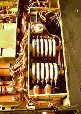
Operation of the ART-13 with the CU-32 on 630 Meters -  Operation must be on CW. This mode of operation utilizes a keying relay in the ART-13 that essentially is "keying" the PTT line. The keying of the ART-13 also provides keying to the vacuum switch in the CU-32 via the U-11/U connector/cable on the ART-13 (U-11/U is only operational if LF is selected on the ART-13.) Since there are three relays involved, the ART-13 keying relay, the ART-13 vacuum T-R switch and the CU-32 relay/vacuum switch, all working with the radio operator's keying, the maximum CW speed will probably be limited to around 15 WPM. I tried a bug and, even at slow speeds (for a bug,) it's too fast for the relays to follow and allow the ART-13 to key "dits" properly. A hand key must be used and top speed seems to be around 15WPM.

Be sure to do your initial testing on LF with the ART-13 in the "TUNE" mode. This limits the power output to prevent excessive current flow when the PA is out of resonance. With a short end-fed wire of about 100 feet in length, you'll probably find that the two LOADING controls will be at maximum and the "plate dip" is fairly sharp. A 200 feet long wire will perform much better and will load up easier.

Running CW signal on 473.5kc from my ART-13/CU-32 combo running into a 163ft end-fed wire I've worked two-way QSOs with NO3M in Pennsylvania, WØSD in So. Dakota, KI6R in California and others. I've copied a few stations in receive with no problems but they can't copy me. I'm sure my transmitting set-up works fine on 630M but many ops don't have a low noise QTH that allows for MW DX reception which is why they don't hear my signal.  Go to "Vintage Longwave Receivers - Part 4" for more details on operating the ART-13 and CU-32 Loading Coil on 630M including a log of stations I've worked on 630M CW.

Operating CW on the ART-13 with CU-32 is a very noisy experience. There are three relays "clacking along" with your sending. While the airplane was aloft there was so much other noise going on the sending relays were seldom heard, especially since the radio op normally was using 'phones. Not much can be done about the noise if you want to run the ART-13 and CU-32 as they were originally operated. Modifications to change any of the method of operation seems to go against the entire idea of collecting, restoring and operating WWII vintage military radio gear in the first place. Sure, it's noisy, but if you use a set of 'phones for "sidetone" monitoring, as the old WWII ops did, it's not too bad. For Sidetone to monitor your sending, the ART-13 provides two jacks to access the sidetone circuit. There is a volume control that is located under the tuning chart. Use a 600Z ohm load, either phones or loudspeaker. You can also listen to the receiver if you're using a separate antenna. Since I'm using a remotely tuned loop on the receiver, I just turn the RF gain down and use the SP-600VLF receiver as the CW monitor. Actually, with this method, I'm listening to the transmitted signal which is probably better since any problems would become quickly apparent.

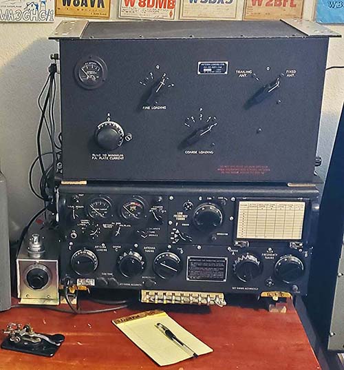
Utilizing "Fixed Ant" and "Trailing Ant" for HF and LF Antenna Selection - The original intent of this switch was to select between a trailing wire antenna or a short vertical antenna, with both antennae being utilized for HF or LF operation. A more useable purpose for this switch is to use the "Fixed" position for the HF antenna. Then the "Trailing Ant" can be used for the LF antenna. When the ART-13 is NOT in LF, the CU-32 is bypassed except for the Antenna Selector switch. So, when operating HF switching to "Fixed Ant" will allow the HF antenna to be connected to the "Fixed" output terminal with the coax shield connected to chassis. Selecting LF on the ART-13 activates the PTT switching of the CU-32 and the antenna selector can be switched to "Trailing Ant" and a LF antenna used. I'm assuming that most ops are going to have a separate LF antenna such as a 200 ft end-fed wire but will use their regular HF antenna for 80M or 40M operation. 

Effective Isotropic Radiated Power  - The EIRP limit of 5 watts is somewhat difficult to determine with any accuracy. This regulation seems to be in place mainly to limit the size of the antenna versus the amount of RF power used and thus to control the effectiveness of the transmitted signal. For example, a full-size 630 meter half-wave antenna is over 1000 feet long. This type of "full-size" antenna would actually exhibit a slight gain when compared to an isotropic radiator (+1.6db.) Therefore, the power input to the antenna would have to be < 5 watts to stay within the regulations (assuming there were no other losses.) With a full-size antenna, even just 5 watts input would result in a formidable signal on CW. However, small, "city-lot-size" antennae will be very inefficient at 630 meters and therefore would exhibit considerable loss rather than gain. That's how the RF power input to a "small" antenna can be very high and yet only result in 5 watts EIRP. Think of the small, inefficient antenna as acting like a "dummy load." You can input lots of RF watts and it does radiate somewhat (a few feet) but it isn't an efficient radiator. So, to stay within the regulations, one has to know the efficiency of their antenna which is determined by the antenna's input resistance and its size. From efficiency and power input you can then calculate EIRP. Antenna resistance usually has to be estimated based on several physical factors with antenna size being the most important. The best information for answering the EIRP question can be found at www.472kHz.org in their section on"630M Antennas" and "EIRP." Their formulae and examples indicate that the "average" ham antenna takes several hundred watts input to achieve 5 watt EIRP.

Propagation and Successfully Receiving LF Signals - A lot of the conversations about prospective 630 meter operation seem to be concerned about the transmitted signal. Very little is written about how to successfully receive CW DX signals in "real time" on the lower frequencies. Propagation on 630 meters isn't ground wave only. At night, skywave propagation dominates this region of the spectrum. It's easy to receive medium wave Airport NDBs that run 25 watts out to distances of 1500 miles. Regional NDBs that run 100 to 400 watts can be received out to the east coast. Transoceanic NDBs will run up to 1KW and can be received well over 3500 miles distance. All of the NDB stations operate into relatively small antennae and therefore their actual EIRP is considerably less than the actual transmitter output power. But, the incredible DX and great nighttime conditions don't last. Long wave enthusiasts consider the "season" to be from the Autumnal Equinox to the Vernal Equinox, or about mid-September to about mid-March. Actually, the best part of the "long wave season" is from mid-November to about mid-January. This is when the conditions are the least noisy allowing very weak DX signals to be heard. So, fall and winter nights or very early mornings work best on 630M. Summer is good for testing or for local QSOs.

Your physical location is another important part of successful 630 meter operation. In noisy urban areas the RFI is so intense that virtually nothing can be heard below the AM BC band. In these locations, a shielded magnetic loop is about the only type of antenna that might allow for some reception. These loops are shielded with a non-ferrous metal tube and, generally, the antenna only responds to the magnetic portion of the electromagnetic signal. A broadband amplifier is necessary with these loops (usually part of the loop design.) Since most RFI is electrical in nature, the shielded magnetic loop provides some relief in noisy areas. Less noisy areas can usually receive DX using a remotely tuned loop. These are just a fairly large coil of wire that's tuned with varactor diodes in parallel with the loop. A pick up loop is mounted within the loop field and that connects to the receiver. Usually, an amplifier isn't required on a remotely tuned loop. In quiet rural areas, it might be possible to use a wire antenna with good results. I use both a large wire antenna and a shielded magnetic loop. I find that I can always use the loop antenna. Most of the time, only from "mid-Nov to Dec to mid-Jan" are conditions quiet enough to allow DX reception on the large wire antenna. One has to remember that the weak signals are always stronger on the large wire antenna but the atmospheric and RFI noise is also quite strong. With the shielded magnetic loop, weak signals are not as strong but the noise is greatly reduced. This results in a better signal-to-noise ratio when using the loop antenna and usually the weak signal can be heard because of that. Unfortunately, in some large metropolitan areas, the RFI noise is so intense, nothing helps,...not even the shielded magnetic loop. In these areas, it might be possible to use Internet accessible remote SDR stations. These types of stations are always located in rural or at least RFI-quiet areas. Some SDRs do have MW capability. For metro-areas, the SDR might be the only solution for MW reception. 

For a complete write-up on how to successfully receive DX longwave signals using vintage radio equipment, go to my article "Vintage Long Wave Receivers - Part 4" - use the Home/Index for navigation.

 
Conclusion - Today, the ART-13 is one of the "hottest" military transmitters around. It seems like everyone that has an interest in older gear, especially military gear, is looking for one or maybe even has one (or two,...or more) stored somewhere for future restoration. However, this isn't really a new phenomena,...the ART-13 has been a popular transmitter with hams for almost seventy years. Articles about converting and using the transmitter go back to the late-forties. As AM operation was replaced by SSB, the ART-13's popularity did drop but the resurgence of AM operation during the early 1990s (and the increasing interest in WWII gear) has brought the ART-13 back to prominence. Though not intended as a ham transmitter, it is interesting that so many of the WWII design approaches for this transmitter's circuit are found in later, post-war, Collins gear (Collins even utilized some of the ART-13 parts in their 32V transmitters.) The ART-13 has had a long history with hams as an easy-to-find, versatile, potent and good sounding transmitter and today there are certainly more ART-13s "on the air" in the ham bands than ever before. References:

1. Various ART-13 Manuals - there are several available from BAMA

2. USAF - Radio Mechanics VOL. 1 - Extension Course 3012 - specifically on the ART-13A and the BC-348. Theory, operation, maintenance, course Q&As, informative about post-war uses and maintenance.

3. Electric Radio - N6PY Bill Feldman, article on ART-13 basics. Tells how to perform an initial checkout of an ART-13. Also, a mod on removing the "locking" current off of the Autotune motor when in standby (for information purposes only.) W6MIT John Svoboda wrote a couple of articles on ART-13 power supply design and on exactly how the loading network operates.

4. Various "Radio News" and other radio magazines from 1946 to 1950 - surplus advertising, conversion articles, prices and other information.

5. Thanks to Mike Everette, W4DSE, for many details on ART-13 history, use, repair and restoration

6. Online - MilSurplus Group, specifics on ART-13 variations by KK5F and WA5CAB

7. Thanks to W6MIT John Svoboda for the heat gun suggestion on the Multiplier trimmer capacitors

8. Thanks to the many conversations with other ART-13 users and enthusiasts that have provided so much information over the years.

Henry Rogers WA7YBS © May, 2011, additions on dynamotors Nov. 2015, addition on restoration ART-13A sn:2054, various corrections and other additions Nov 2015,   new header photo & surplus market availability info Feb 2016, Correct knob sync info Dec 2017, added 630M info Jan 2018, added "ATC cnvt'd to ART-13 - SAAMA Survivor" Mar 15, 2021, Warnings added regarding the auxiliary C values and PA tube saturation 2022,


ART-13 Part 1                  ART-13 Part 2                    ART-13 Part 3                    Return to Home Index


Radio Boulevard
Western Historic Radio Museum

 Vintage Radio Communication Equipment Rebuilding & Restoration Articles,

 Vintage Radio History and WHRM Radio Photo Galleries

1909 - 1969

- 60 years of Radio Technology -


This website created and maintained by: Henry Rogers - Radio Boulevard, Western Historic Radio Museum © 1997/2023