Radio Boulevard
Western Historic Radio Museum
 

Rebuilding the ART-13 Transmitters

Part 3
 

Basket Case Restoration of a USAAF Stewart Warner ART-13A

Restoration of a typical example USN Collins ART-13

Restoration of a "Wasp's Nest" ART-13A


by: Henry Rogers WA7YBS/WHRM


T-47A/ART-13 "Basket Case" Restoration

This example of the restoration process features a really awful condition T47A/ART-13 (aka: AN/ART-13A) that was part of a trade-deal. Missing parts, extensively disassembled and cosmetic condition issues make this an excellent example to illustrate the types of problems involved with the restoration of "Basket Case" projects - and, perhaps, why to avoid them. 

The Big Trade - The photo to the right shows the USAAF T47A/ART-13 that I got in a trade. The fact that it was almost completely disassembled didn't matter since it was initially considered just a "parts set" to use for the restoration of another nearly complete US Navy Collins T-47/ART-13 that was also included in the trade. I know,...you want the story about the trade, right?

I got an e-mail offering two "rough" ART-13 transmitters, a "nice" BC-312 receiver and an "okay" BC-344 receiver plus several boxes of military radio parts in trade for audio gear or a tube tester. After a couple of e-mails we settled on trading a nice, working Hickok 600A tube tester and a "needs restoration" HP-712A power supply for a "load" of military gear that included the two transmitters and the two receivers. Photos were sent both ways and we both knew the condition of everything involved in the trade. A quick daytrip to Lafayette, California resulted in dropping off the tube tester along with the HP power supply and coming back home with my Subaru Outback packed full of military equipment and parts.

First Things First - The first project was to restore and get operational the Navy T-47/ART-13. This project took a about seven weeks to complete, which included designing and building a suitable power supply for the transmitter. I began using this T-47/ART-13 a lot and really enjoyed operating it. I didn't really consider even looking at the other ART-13 transmitter because it was a "basket case" and only a source of parts. Then, a few months later, fellow ART-13 enthusiast, W7MS, happened to mention "on the air" that he had a second ART-13 in storage that was his "hanger queen." This got me thinking that I probably could take my "parts set" and put it together enough to be a "hanger queen" that would be "for display only"  in the Western Historic Radio Museum (the museum I had in Virginia City, Nevada 1993-2012.) Functionability wasn't the goal, just a fairly complete, reasonably good-looking ART-13 for a museum display.


photo above: The ART-13A as I got it from the "Big Trade." Note that some of the sheet metal is setting beside the transmitter chassis 


photo above: The ART-13A after the "parts hunt" located most of the missing parts.

The Parts Hunt - As I searched for the parts I was finding boxes that had been picked up at the Big Trade but that I hadn't really looked in carefully. Looking through four large boxes turned up all of the sheet metal parts. I looked through more of the smaller boxes and plastic bags finding nearly all of the components that were missing. I began to think this project might progress from "hanger queen" to "restore and get it operational." After a thorough search I ended up with a pile of parts that looked like the photo to the left. In the photo, all of the sheet metal parts were just setting in place, so I could see that I had all of the pieces. Note that the combination bottom cover and shock mount rails isn't even in place but is leaning up against the side of the transmitter.

No amount of searching could find these missing parts: R-121, R123 and R-124. These are the wire wound resistors that are located in the rear compartment with the 811s and the 813. Additionally, the rear triangular bracket that supports the side panel for the blank panel couldn't be found. The MCW/FCI module and the Audio module "remains" had been sometime in the past totally disassembled for parts and I could only find the chassis and a few parts to those units. Also, the multimeter was unusable due to a broken glass that long ago had allowed the meter needle to become broken. Everything else that had been removed from the transmitter I was able to find in the various boxes of parts. This meant the transmitter was about 95% complete, just mostly disassembled.

In my "junk boxes" had two spare MCW/FCI modules so that wasn't a problem. KØDWC supplied the triangular bracket by giving me an entire blank panel assembly. I purchased an Audio module off of e-Bay. The meter and the wire wound resistors were obtained from Fair Radio Sales. So now, on to the restoration work.

Unusual Reassembly - The most difficult to repair damage was the three flexible plate cap connections (E-109B) for the 837 VFO tube and the two 1625 multiplier tubes. These consist of a flex connection and a brass tube that is soldered to a stud that is mounted through a pair of ceramic standoffs (top and underneath the chassis.) These three connections were "snapped" off leaving the stud inside the brass tube and a flush threaded rod with a nut on top of the insulator. After trying to drill out, tap and other methods that didn't work, I decided that I should solder a flange to the brass rod and then sweat-solder that to the nut on top of the insulator. This worked quite well and seems pretty strong.

To reconnect the large buss wire connections for the LF relay (K-105) and the Antenna push connectors I made brass sleeves out of shim material. These cylindrical sleeves were fitted to the cut buss wires and then soldered. The buss wires had to be re-tinned first and it does take quite a bit of solder to fill this kind of splice. The benefit is that it's a really strong joint and it looks like a professional repair job. See photo right.

The Interlock switch had the housing broken. Fortunately, it was possible to use epoxy to repair the housing and get the switch working again. Also, the mounting for the plate blocking capacitor used a pair of fiber screws into the ceramic standoffs and since one of the fiber screws was broken, I repaired the mount using epoxy.

A Wiring Error? - During the reassembly of the meter/switch panel I had to re-install the meter shunts and loads that are mounted with a long screw to a projecting tab that is on the back side of the right side inner panel. In checking the wire locations versus the schematic I discovered that the Meter switch had a wiring error. This was INCREDIBLE since it meant that the positions for Grid Current and Battery Voltage couldn't have worked. I used the wiring diagram (not the schematic) to confirm this was indeed an error. I think this must have been a later error done during a repair cycle that replaced the meter switch. It's likely that the transmitter didn't pass one of its tests after the rebuild and was set aside for a later checkout and repair cycle that was never done. The wiring error probably happened at SAAMA. The San Antonio Air Materiel Area (Kelly AFB,) performed extensive aircraft repair and repair of all aircraft equipment from 1947 up to 1974. This ART-13A has a SAAMA stamp for MFP application dated 15 Sept.1954. It's likely this ART-13 never made it out of the repair depot and was sold as surplus at some later date. The error was the interchange of two wires going to the Meter switch that introduced a conflict between the Grid Current and Battery Voltage. After switching the two wire positions, the meter then read Battery Voltage and Grid Current correctly. It's unlikely that this problem would have gone unnoticed, so why it wasn't corrected at SAAMA is a mystery. The photo left shows the SAAMA MFP stamp on the chassis.
Replica Calibration Book Pocket - The Calibration Book pocket was missing from this ART-13A. It appeared like the rivets were aggressively pulled out since the metal was slightly distorted. I took measurements from the USN T-47 that had its original book pocket and had a replica made at a local sheet metal shop. I had to add the curved cut-out and the edge treatment since this would have complicated the project for the metal shop. Once I had the piece shaped correctly, I had to remove the Autotune cover so I could accurately measure where the mounting holes had to be drilled. Also, there was some "body work" necessary to get the holes in the cover cleaned up. A close inspection of the original book pocket revealed that the inside was painted gloss black and the exterior was black wrinkle. The original wrinkle finish paint was a two part process that used a catalyst sprayed onto nitrocellulose lacquer to activate the wrinkle by baking in an oven. It's normal for older sheet metal pieces to be gloss on one side and wrinkle on the other. I painted the pocket with gloss black lacquer on the inside and Krylon Black Wrinkle Finish on the exterior. The original book pocket was mounted with round head rivets. Fortunately, I had the same kind of rivets in one of the parts drawers around here. The rivets are a tight fit and when the shaft part is deformed it pulls the mounting flange tight. The three photos below show the various stages of making the replica book pocket and the larger photo to the right shows the pocket mounted on the ART-13A. I still need to make the replica plastic tubing covered chain that attaches the book to the book pocket. A small hole at the lower right front corner of the pocket has a rivet/washer combination that holds the one end of the chain and a lanyard ring attaches the chain to the book binder ring. See updated photo at the end of this section showing the book, chain and ring installation.

Cosmetics - As can be seen in the "before" photo above, the panels did have some aluminum corrosion that was "popping" through the paint. I used the method described in the restoration section above to touch up the panels. This ended up with a combination of touch up and then using the "wash" technique. This resulted in the panels looking kind of flat but even and with some wrinkle to the finish. See the "after" photos below.

Since so much of this ART-13A was disassembled and parts were obtained from other transmitters to complete its assembly, the distinctive "gold" color of the MFP coating had to be applied to many parts. Probably the most difficult to match was the replacement Audio Module since this was a large piece that didn't have any MFP coating when obtained. Fortunately, I had a few parts from the original Audio Module to see just how much MFP was on it.

Quite a few years ago, I had some yellow-tinted nitrocellulose lacquer mixed for me. This is very close to what MFP was except it doesn't contain a fungicide or that distinctive MFP odor. I thinned this yellow lacquer down using clear lacquer and lacquer thinner to get the correct "look" of the MFP when sprayed onto the Audio Module. >>>

>>>  All of the other pieces that needed to be MFP coated were small - like screw heads and nuts, solder joints, sheet metal edges, etc. This was applied with a small paint brush direct from the tinted lacquer can. Looking at the finished chassis photo below shows the final appearance.

A new Settings Chart was necessary and an excellent one can be down loaded from BAMA. Just print it out on heavy manila paper and it will look original. New plastic for the chart can be found many places. I salvaged the plastic from a cheap picture frame.

Final Missing Parts Installation - The large wire-wound resistors, R-121, R-123 and R-124, were obtained from Fair Radio Sales. Luckily, when the originals were removed the wire must have been cut close to the resistor terminals because I did have enough wire left for the connections to the new replacement resistors. These large wire-wounds mount with an aluminum stud that is threaded on each end. The stud is mounted to the chassis with a screw and lock washer from underneath the chassis. Then several mica washers are placed over the stud and next to the chassis. Then the resistor is placed over the stud and secured with several more mica washers, a flat steel washer, a lock washer and finally a screw. Without R-121, you can't do any real "voltage on" testing because the +28vdc to the filaments is routed through this 0.8 ohm 50 watt resistor first. With the installation of these resistors the filament circuit is complete and testing can begin.

Testing - I tested both the MCW/FCI module and the Audio module by plugging them into my working Navy T-47/ART-13 to confirm they were operational units. The MCW/FCI module worked fine but the Audio module needed extensive repair (what else can you expect from an eBay purchase?) Two resistors had to be replaced. The audio input resistor had overheated and the value changed along with burning off part of the color code paint. The carbon mike Z load resistor had been changed from the original value of 15K to 4.7K (a common upgrade found in later modules that increases the mike bias for better response from typical carbon mikes.) I reinstalled a 15K resistor (just to be original.) A quick operational check showed that I still had some distortion that resulted in "harsh" sounding audio. The problem was caused by a defective coupling capacitor between the 12SJ7 plate and the 6V6 grid (C-204.) Since this was one of a "stack" of three molded capacitors (and one other capacitor already had broken mounting tabs,) I went ahead and replaced all three caps with SBE Orange Drops. Additionally, it was noted that the Jones plug was partially coming apart due to a bent over tab not holding the back plate in place. After several attempts to remount the back using the tab, I finally had to resort to a combination of epoxy and the tab to hold the backing plate in position. After these repairs, the Audio module output sounded great.

Pre-Testing - During the re-assembly of this ART-13A most of the sections that were affected by the disassembly were tested. A thorough inspection is necessary before powering up any transmitter. All components that could be tested with a DMM were given a cursory test. Be sure to test the Plate Blocking capacitor for shorts since this condition would allow for full +HV to be on the antenna system. All tubes are tested except for the 813 which can be given a quick filament continuity test and a quick shorts test with a DMM. Clean all the ceramic insulators.

Initially, I just connect +28vdc and make sure all of the low voltage circuits work. This test turned up a problem with the Autotune. Through the system would motor drive to the zero position it just remained at zero and would not continue onto the presets on any channel selected. Since the Autotune essentially wouldn't shut off, the transmitter couldn't be tested further until this problem was fixed.

Problem Details

Autotune Problem - I guess this transmitter was pretty much a basket case for quite sometime and the front cover was off of the Autotune mechanism. At that time the Forward Limit switch was hit or bent enough that it wouldn't open when the actuator arm contacted it. Momentary breaking of the contact would cause the Autotune to complete its cycle. I bent the contact arm just enough so that the contact would open at the Forward limit position and reverse the motor to complete the cycle. This got the Autotune working correctly.

+HV and +LV Test - When everything looked ready, I decided to go ahead with a full test. With the +28vdc on operation was normal and I allowed the tubes to warm up. After a few minutes, I switched to TUNE and pressed the THROTTLE SWITCH (T.S. jack - a remote PTT line.) This resulted in the immediate blowing of three fuses in my power supply. Two fuses were the primary fuses to the +HV and +LV transformers and one fuse was the +HV output. Since my power supply is fully fused in every input and output, no damage occurred there but certainly something was wrong the the ART-13A.

Problem One - The PTT line was grounded. This caused most of the problems involving the +400vdc. I traced the source of the problem to a solder bridge that I created when reinstalling K-104 - oops. Removal of the solder bridge cleared the PTT problem and the ART-13 would now operate and not blow the +400vdc fuse in the power supply.

Problem Two - The +1400vdc continued to blow both the transformer primary fuse and the output fuse in the power supply. A close inspection of the 813 tube socket revealed a burnt R-112, a 47 ohm 1 watt carbon resistor acting as a screen load. I replaced R-112 with an NOS resistor but wasn't too confident that it was causing the problem. I decided to also replace the old National Union 813 I had been using with an NOS Sylvania 813. These two changes got the +1400vdc and the transmitter operational and working fine.

The Initial Shake Down Test - This test used my homebrew power supply that I normally use to power the Navy T-47/ART-13 to power this T-47A/ART-13 version. This supply provides about +1400vdc for the +HV and results in about 160 watts output with the Navy transmitter. With the NOS Sylvania 813, this ART-13A had a somewhat higher output power running around 190 watts. I decided to use a variable capacitor (instead of a fixed value capacitor) for the Auxiliary Condenser so I could load the antenna exactly. This setup allowed me to adjust the ART-13A for about 200mA total plate current and have a power output of about 145 watts. This allows the transmitter to run in a very stable manner since the power supply current carrying capabilities are not "pushed" and the +1400vdc plate voltage remains fairly constant during operation. The reduced power also allows for easy 100% modulation without "loading down" the plate supply (which was what was happening at 190 watts output.) Monitoring with earphones listening on an RCA CR-88A (with no antenna connected) sounded great. Watching the oscilloscope looked great. The next test was to call up KØDWC and have him listen to the signal at his station (next block up the street.) With this set-up, I can also hear what Chuck hears via the telephone connection. Finally, a true "On the Air" test with the Sunday morning Vintage Military Radio net was next (3974KC - 8AM Pacific Time.) The "On the Air" test was successful and the reports that came back were all positive.

photo left: The chassis of ART-13A sn 417ACG after restoration. Note the distinctive "gold" appearance from the MFP coating.

CW Mode Inoperative - This problem was actually found after I had used the ART-13A "on the air" in the VOICE mode. I decided to try some 40M CW with the ART-13A and after loading up in the VOICE mode, I switched to CW. When switching to the CW mode, the transmitter should show plate idling current and when depressing the key the plate current should increase up to slightly less than the VOICE plate current (since you don't have the Modulator idling current.) No idling current was showing on the meter and when the CW key was depressed the keying relay operated but no plate current was indicated. A quick check of the schematic showed that the problem was most likely in the operation of the CW mode relay, K-103. A quick check accessing the K-103 relay coil terminals for testing through the vent holes in the rear panel of the transmitter showed the coil was open.

An original replacement K-103 would involve quite a bit of time to locate. Since rewinding the coil of the relay wasn't really too difficult, I decided to proceed with a repair instead. First, to access K-103, the transmitter bottom had to be removed. Then the bottom-rear panel can be removed and the two relays, K-103 and K-104 are mounted on the inside of that panel. I tagged all of the wires soldered to the 10 terminals on K-103 to make reinstallation easier and then unsoldered them and dismounted the relay. The relay coil is held in place with a single screw. Once the coil is out of the relay, then all of the original magnet wire has to be removed. By the way, the "break" in the wire never seems to be at the beginning of the wind. I just cut all of the original wire out with an Exact-O knife and remove it with needle nose pliers (or my fingers.) I measured the thickness of the original wire so I would know what gauge magnet wire I would need. The original seemed to be 33 gauge but all I had on hand was 32 gauge.   >>>

 >>>  I used a motor driven coil winder I had built about 30 years ago. It's very basic in design and uses a "light dimmer" control as a motor speed control for the small sewing machine motor. This allows me to wind a solenoid-type coil pretty fast. I threaded an 8-32 stud into the tapped hole in the coil spool so I could install that stud into the chuck of the coil winder shaft - see photo below. You have to start the winding slowly and this is where a variable speed motor control is really necessary. Once the motor speed is about 100RPM, it is easy to just use your fingers for tension and to also guide the wire onto the spool. When it appears that the coil is about the proper dimension, I stop the motor and clean a spot on the wire so I can measure the DC resistance from the "inside" terminal to the clean spot - this would be the total DCR of the coil so far. I'm looking for around 125 ohms DCR and when that is achieved, the coil is finished. After the coil was wound, I wrapped it with black electrician's tape and then lacquered the exterior of the coil. The original coil had "125" stamped on the side, so I added that to this replica coil and then mounted it back in the relay. Operation was just like an original relay.

Resoldering the wires to the relay was easy since all of the wires were tagged and their proper location readily found. After all the wires were connected and soldered, I coated the solder joints with the yellow-tinted lacquer to simulate MFP coating. Below are photos showing four of the steps to completing the repair of K-103.

Testing the CW Mode - The ART-13A was put back into the operating position and connected back up to the station antenna system. My initial test was on 3974kc, our Vintage Military Radio Net frequency, but since it was mid-day there would be no activity. This test showed that the ART-13 did indeed function in the CW mode now. The next test will be an actual CW QSO on 40M.


photo above: Coil spool in the chuck - ready to wind.


photo above: The coil after winding.


photo above: The completed K-103 with new coil


photo above: A repaired K-103 installed on the back panel

Final Assessment - It's hard to believe that the ART-13A in the photo to the right is the same "parts set" shown at the beginning of this section. Though this ART-13A turned out really nice and works great, let's consider what was necessary to get the transmitter operational. First, I had to find an Audio module - $67 with shipping off of e-Bay (and I had to repair/restore it.) A set of three wire wound resistors - $45 from Fair Radio. Plate Meter - $35 with shipping, Fair Radio. The MCW/FCI module that was a spare had been purchased earlier for $30. The sheet metal piece was $21. The total for missing parts was $198. Luckily, I didn't have to buy any tubes. In addition to that, figure that I had to spend about two weeks putting the transmitter together and getting it operational. I still have to build an AC operated power supply specifically for this transmitter. Of course, I did essentially get this ART-13A as a "freebie" that was included as a "parts set" for the Navy T-47. So, I started with a "zero investment" but, as far as saving any money on this project - that didn't happen. Unless you really enjoy all the aspects of restoration - parts hunting, cosmetic restoration, mechanical reassembly, testing, troubleshooting and repairing, it's probably best to avoid these types of "basket case" projects. The positive side is, of course, "bragging rights" to having saved another ART-13 from the oblivion of the scrap heap.


photo right
: The ART-13A sn 417ACG after completion of the restoration. Note that the two meters don't match. This is commonly found on many ART-13 transmitters and is probably due to past depot repairs, however, in this case the Plate meter is a replacement acquired from Fair Radio Sales.

UPDATE - ART-13A "Basket Case" -  March 2013

photo above: This is the ART-13A "Basket Case" as it now looks in 2013 in our Vintage Military Radio station in Dayton, Nevada. This configuration with the BC-348-R receiver would be referred to as the ARC-8 but to be accurate that ARC-8 should be powered by dynamotors and this station actually is using AC power supplies for both receiver and transmitter. Note the auxiliary capacitor to the left of the ART-13. This air variable capacitor allow precise setting of the loading of the transmitter. Details on the construction of an auxiliary capacitor box is in the section below "Operating the ART-13 on the Ham Bands Today." Note that there is now a Calibration Book in the book pocket along with the correct type chain and sleeving for securing the book to the pocket. Also note that all of the panel screws have been changed to stainless screws along with using external star washers. Most ART-13A transmitters that I've worked on seem to have stainless (or at least silver finish) screws with external star washers rather than the "raven finish" (black) screws and internal star washer used on the earlier Collins' versions.
We're really never finished with projects like the "Basket Case" ART-13A. We're always keeping watch for parts needed to improve the transmitter's appearance or performance. This ART-13A needed a Calibration Book and I found an excellent example on eBay. Although it wasn't cheap ($70) it was in very nice condition. This required finding the right kind of chain to secure the book to the pocket and the right kind of sleeving to cover the chain.   >>>
>>>  A method of securing the book to the chain and the chain end to the pocket were also needed. The correct chain was found at a specialty hardware store and the sleeving was salvaged from an old piece of rotor cable. I made a "fake rivet" out of a brass screw and nut for the attachment to the book pocket and then painted the "fake rivet" flat black. The installation looks very original with the right amount of patina.  (See close up photo to the right.)

I was also able to remove some other items needed from a "parts set" ART-13 that belonged to KØDWC. The original Instruction Plate on the lower front panel was in poor condition but the "parts set" had one in nice shape. If you carefully drill the back of the rivets just enough to remove some of the rim they can be "punched out" with a small metal punch. This saves the rivets for reuse. The new Instruction Plate was mounted by installing the old rivets and then deforming the back of each rivet with a suitable punch. The front of the plate and the rivets have be held against a piece of hardwood to keep the rivets tight while punching. To fully secure the plate, use clamps to make sure the plate and rivets are tight against the panel and then apply a small drop of 5 minute epoxy to the back of the rivets. When that's cured, the plate will be secure and tight along with looking perfect.

I also replaced the mismatched meters with a set of matched Weston meters from the "parts set." Also, the original K-103 that I repaired was replaced with a good condition, functional K-103 unit from the "parts set." Also, the old "repaired" Interlock switch was replaced with a good condition, functional original.

I was given the OA-17 LF Oscillator as pre-payment for some work on a T-368 transmitter that is owned by KØDWC. The OA-17 just about completes this ART-13A "Basket Case" with the only other item needed being the shock mount.
 

Another UPDATE: "Basket Case"
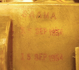
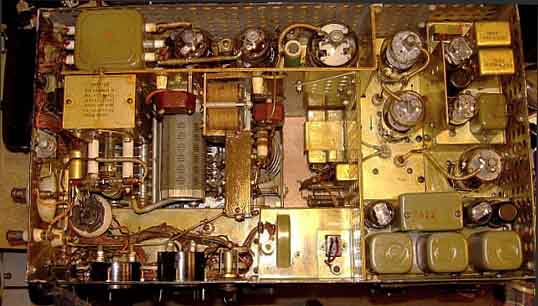
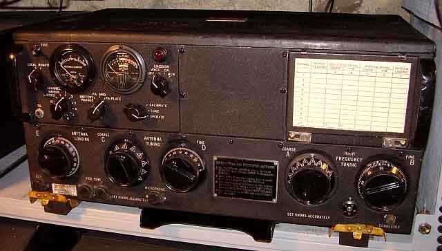
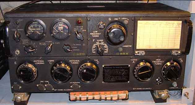
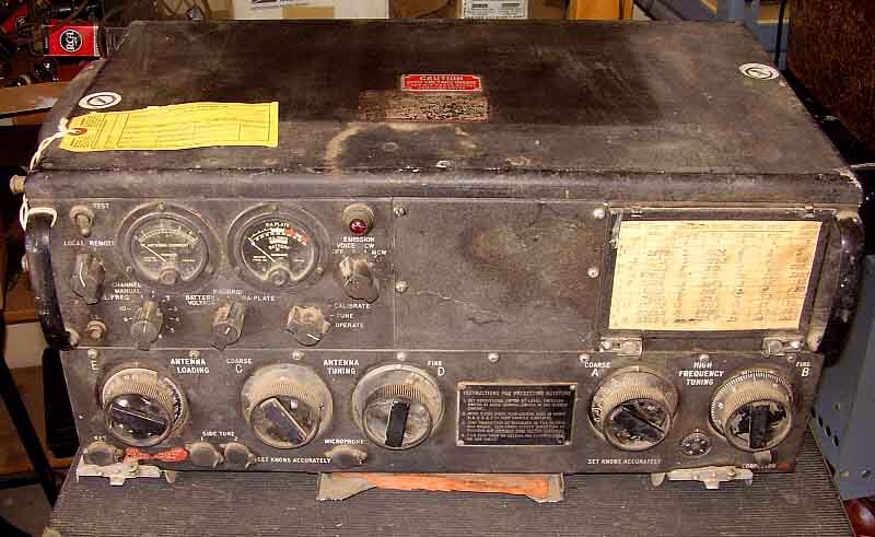
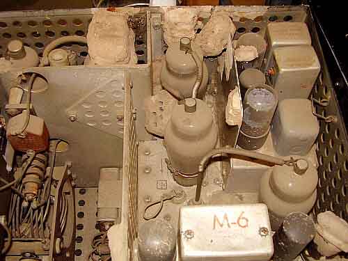
 ART-13A aka "The SAAMA Fugitive"

August 29, 2021 - Just to let everyone know,...this 75+ year old gear doesn't run forever without some problems turning up once in a while. During the Vintage Military 
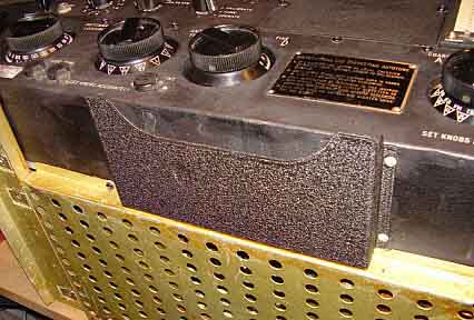
Radio Net on August 29, 2021, the "SAAMA Fugitive" ART-13A transmitter had a failure of the PTT function. Pushing the TEST switch seemed to operate K-102, the sending relay, but not much else happened. I finished the net using a different station and decided to look at the SAAMA Fugitive that afternoon. I suspected the Dyna-Sim Mark I had blown a fuse but that wasn't the case. Just to be sure the Dyna-Sim wasn't at fault, I used it to power up the ATC transmitter with no problems. So, the failure was with the ART-13A. A quick check of K-102 
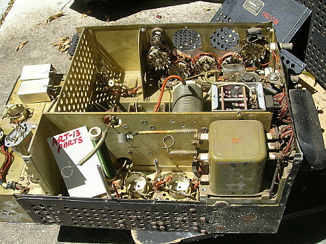
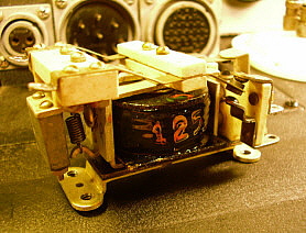
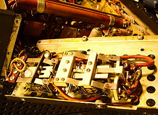
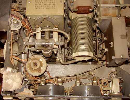
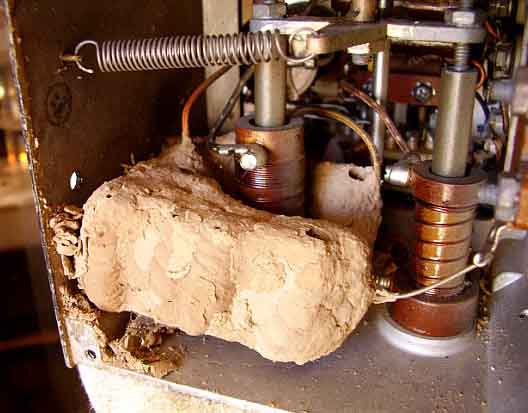
showed that it was indeed operating. The next check was K-104. K-103 and K-104 are both located in the rear bottom section of the transmitter, just below the 813 and 811 tubes. K-103 controls the CW function and K-104 controls the VOICE parts of the transmitter circuitry which includes parts of the PTT functions. Luckily, one can access these two relay's (K-104 and K-103) coil terminals very easily through the vent holes, so checking is no problem once the ART-13A is removed from the station set-up. K-103 showed 125 ohms DCR for the coil which is correct. K-104 showed an open coil which caused the relay not to function. Both of these relays experience a lot of use when operating the ART-13, so they are components that are often found defective in "as-is" ART-13s that haven't gone through a rebuild. But, I haven't ever had one of these relays actually fail after a rebuild,...until now. I should mention that the SAAMA Fugitive has worked without a serious problem since I did the rebuild on it in 2011, so ten years without a failure is pretty good reliability. Unfortunately, a check of the spare parts boxes and the parts sets revealed that the all of the K-104 relays had been removed earlier and apparently had been installed in other ART-13 transmitters being rebuilt. I have rewound these relay coils before. It's not difficult. In fact, there's photos of the process just up this page a little bit (rewinding the K-103 solenoid.) Disassembly of the transmitter is required so it sounds like a winter project. Update when the rework gets started.   

Oct 23, 2021 - While looking for some C-clamps that happened to be next to my large box of various types of boxed and bagged pilot lamps I noticed that in the large box of lamps were two spare ART-13 relays, K-103 and K-104. Why were they in the lamp box? Who knows. I thought I remembered that both of these relays were good, usable units. K-103 was operational. Unfortunately, K-104 had an open coil. Figures. But, I can do the relay rebuild anytime and then just do a simple R&R on the ART-13A.

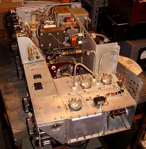
Nov 3, 2021 - I went ahead and put the SAAMA ART-13A on the bench. To extract K-104 the bottom cover and the lower back panel have to be dismounted. Once this is accomplished (easy) then the seven wires that connect to K-104 have to be unsoldered. I made a sketch that numbered the connections to K-104 and then used masking tape on the individual wires to identify them and their proper connection. An examination of K-104 confirmed that it indeed had an open coil. Looking at the coil it's apparent that it had gotten very hot over the years. The black plastic covering (like tape) over the coil was slightly melted and I could see that the varnish had also "bubbled" around the edges indicating a lot of heat. K-104 is energized 100% of the time when the ART-13 is in the VOICE mode.

Nov 4, 2021 - I disassembled K-104 to remove the coil. The stranded wires that connect the coil ends to the terminals were unsoldered and the terminals straightened. If the terminals are bent they will interfere with winding the new coil. The only way to remove the old coil is to cut the old wire out. I use an Ex-acto knife and cut through each layer to remove. It still takes about 15 minutes to cut through the layers to completely remove the old wire. I measured a couple of strands of the old wire and got 0.007" diameter which is 33 gauge wire. The proper measurement of the DCR of the completed coil should be 150 ohms.

Motorized Coil Winder Problems - I have an old coil winder I made using a sewing machine motor and a motor speed control. Belt-driven shaft, bearings and a chuck for holding the coil form. I made the coil winder about 1980 or so and have used it many times to rewind lots and lots of audio transformers and solenoid coils. In fact, I used it to rewind a solenoid coil to repair K-103 for this SAAMA ART-13A. That relay was replaced with an original K-103 out of a parts set sometime later. An operational check of the coil winder was performed and I discovered that the "motor speed control" was now non-functional. These are really only a light-dimmer control so I purchased a new 600 watt version at the local hardware store. This got the coil winder motor working but the rubber drive belt didn't stay in position on the shaft now and would ride-up until it jumped against the motor shaft front bearing mount. I'm going to have to fit a guide onto the 3/8" diameter shaft to keep the belt in position. One of these days, I'll be able to rewind the K-104 solenoid.
 

Nov 22, 2021 - More Coil Winder Issues - Though I haven't spent too much time on this project lately, I'm sure that I've spent the majority of time trying to fix or redesign this motorized coil winder. I added a rubber grommet on the 3/8" shaft to act as a guide for the belt and that works quite well. I had to install a longer AC power cord so I could do away with extension-cords. Then the rubber belt broke. That required finding something that would work as a belt, like a super heavy-duty rubber band. I had trouble with the method I had used to limit the shaft thrust movement. I finally removed the screw that had been acting as a thrust limit and replaced it with two rubber grommets on the shaft - one on each side of the back bearing housing. Simple - and it works. Limits the shaft thrust movement very well without placing any load on the shaft. I had to use a wrap of friction tape on the shaft to increase belt traction. After spending several hours redesigning this coil winder (that I had used many times before without 
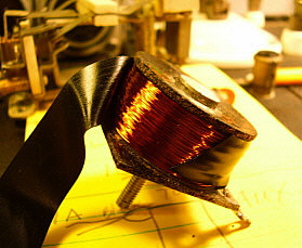
any problems) I finally was ready to wind the solenoid coil. The coil winder did perform really well and I had the solenoid coil wound in about five minutes. I wound a little extra wire to be sure I could trim the DCR by removing wraps. I measured 230 ohms at first. After several wrap-removals, I was at 175 ohms, which was close enough*.

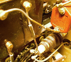
I finished off the solenoid with several wraps of black electrical tape. 
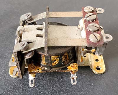
I then used a rubber stamp with gray paint and added "150" to the side of the solenoid as the originals had. I painted the solenoid with 
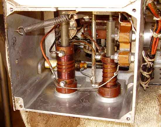
yellow-tinted lacquer to simulate MFP coating. I completely reassembled K-104 and tested its operation using a DC power supply set to +26vdc. K-104 operated as it should (I thought.) It's now ready to reinstall into the SAAMA fugitive. The rebuilt K-104 is shown in the photo to the right.

Nov 23-24, 2021 - I was so confident of the rewind-repair of K-104 that I completely reassembled the ART-13A and even moved it into the operating position only to find out that it still didn't work in VOICE,...bummer. I moved the ART-13A back to the bench and disassembled it,...again. I had to bring the Dyna-Sim Mark I along to power-up the transmitter so I could troubleshoot the problem. A few voltage checks and it looked like K-104 was actuating as it should but the PTT contacts weren't "making" although it looked like they were. I cleaned the contacts with DeOxit on a paper strip pulled through the contacts and then adjusted them for good contact. The ART-13A now had full output on VOICE and the PTT functioned correctly. I must have slightly bent or "tweaked" the contact arm on K-104 with all of the rework performed on it. I did check its functionality but I didn't check the contact resistance before installation, hence the "bench re-visit." So, everything was put back together again and the SAAMA Fugitive was put into the operating position and tested hooked-up to the antenna - 110 watts carrier output and ready to use. "On the Air" for the MRCG net had the SAAMA Fugitive in VOICE mode for one and a half hours (100% continuously energized K-104) with no problems.

* The original solenoid DCR was 150 ohms. As mentioned, the original wire measured as 33 gauge and I had to use 34 gauge. Since there's slightly less current carrying capability using 34 gauge, I purposely increased the DCR slightly to compensate. It's not critical since it's just an electro-magnet but operating a solenoid coil on DC does build up more heat than if it operated on AC and K-104 is 100% energized while in the VOICE mode.


USN/Collins T-47/ART-13  "Restoration of a Typical Example"

This example of the restoration process features a very complete, good condition ART-13. Only minor disassembly and only one missing part made this restoration straight-forward and is typical of most ART-13 restorations today.

Deceiving Appearance - The photo to the right shows the other ART-13 involved in the "Big Trade." Though it looks to be another "parts set" it's actually in pretty good shape. With this Collins-built USN T-47, all of the parts were present except for the MCW/FCI module. The obviously missing meters were carefully wrapped in bubble-wrap and in one of the parts boxes. Knobs, the lid, and other minor items that were not on the transmitter were in the boxes. The Audio Module was partially disassembled but this was minor and only involved replacing some screws and nuts. Tubes were carefully wrapped in one of the parts boxes. I found a MCW/FCI module off of eBay. These are usually pretty cheap with this one costing $15 plus shipping.

Reassembly and Body Work - This transmitter required the same sort of searching through the parts boxes but on a much smaller scale. All of the parts were easy to find since they were obvious items that were very recognizable. Note that the handle on the left side is bent. Actually, the sheet metal panel is bent. This required removing the handle and using a clamp and small wooden blocks to straighten. Even doing this carefully resulted in some of the paint chipping off. The area was painted with Krylon Black Wrinkle Finish using a small brush. Then the area was heated using a heat gun to activate the wrinkle. After the wrinkle had dried overnight, I matched the actual color of the panel with Artist's Acrylic paint.

Everything needed a good cleaning. I used Glass Plus for most of the cleaning. The wrinkle finish was cleaned using a soft brass brush and Glass Plus. Afterwards, Armor All was used to improve the looks of the original paint. The knobs were soaked in dish soap and water for about an hour and then cleaned with a tooth brush. Armor All can also be used on the knobs.


photo above: This USN T-47/ART-13 is actually a pretty good candidate for restoration. An added bonus is the Navy version of the OA-16 LFO is installed. It looks pretty bad in this photo but all of the parts were in boxes and the transmitter only needed to be reassembled.

Power Supply Construction and the Amazing Nemic-Lambda - I built a power supply entirely out of my junk boxes. It was a pretty standard for a tube rectifier design and used 866MV rectifiers for the +HV and a 5U4GB for the +LV. The unusual approach was to use a modern and very small Nemic-Lambda 10A power supply for the +28vdc. I saw this supply on eBay with a "Buy it Now" of $25. I couldn't resist the price so I purchased it. When it arrived I thought I had been sent the wrong item. It was about 3 lbs total weight. The size was 4"W x 4"T x 9"D. Nothing that small could provide +28vdc at 10A! A set-up and test proved to me that modern switching power supplies are amazing. I monitored the output with an oscilloscope and was amazed that the ripple voltage never changed from minimum load to maximum load. I left the Nemic-Lambda running the ART-13 +28vdc requirement for one hour with no problems and no over-heating. Also, older switching power supplies had a reputation for very noisy outputs with a lot of "switching noise" apparent on an oscilloscope when monitored. This Nemic-Lamba has no "switching noise" on the output whether at full load or no load. Simply amazing. The homebrew power supply is described in more detail in the "AC Power Supply" - "Hommage a le Valve" section of this web-article. Testing - Initial testing showed that this T-47/ART-13 worked with no issues. I was amazed that the transmitter had been partially disassembled and yet went together easily and worked on the first try. Initially, I used a fixed 400pf ceramic external capacitor to allow matching to my tuned dipole. I was able to get about 165 watts output with the transmitter but the audio sounded weak and under-modulated. I had selected the pair of 811 tubes for "matched" equal test results without too much regard for their maximum test readings. The T-47/ART-13 requires 811s that are at least measuring "minimum acceptable" to provide adequate modulation. Replacing these "weak" tubes with better (though not exactly matched) condition tubes resulted in great modulation characteristics.


photo above: The completed T-47/ART-13 sn 4628 built by Collins Radio Co. for the USN. Note the rubber mounts that are under each of the shock mount rails. These help to elevate the bottom of the transmitter to provide cooling. The shock mount rails are the early style that are separate from the bottom cover.

Final Assessment - This was the first T-47/ART-13 that I had worked on and restored to working condition. It was a fairly easy project that took about seven weeks to complete, including the design and building of the "Hommage a le Valve" AC power supply. The power supply was actually at least 80% of the time required to complete the project. This is normal in the restoration of your "first" ART-13 since from then on you have the means to easily power-up your next ART-13 projects.

At first, I had the Channel Selector switch set to MANUAL while I was learning how the transmitter operated. After a week, I started to setup some of the Autotune channels. I was generally operating on 3870kc or 3974kc and power output was about 160 watts.

For audio I used some military microphones at first but discovered they didn't fully modulate the ART-13 at the increased RF power. Although specific mikes are called for in the manual, these mikes seem to only provide sufficient modulation if the carrier power is reduced to around 100 watts. These were carbon mikes and this audio module still had the 15K resistor that, in later versions of the ART-13, was changed to 4.7K for better carbon mike gain. Using the "Dynamic" switch position, I found that using a DH-50 crystal mike (with a Kobitone element) on an Astatic TUG-8 stand (amplified) provided fully adjustable audio drive with more than enough audio output for full modulation at 150 watts output power.

This ART-13 project was fairly easy and no serious problems were encountered. For the most part, if a complete and good physical condition transmitter is purchased, this will give you the best chance of completing the project with very few, if any, problems.

UPDATE: Collins T-47/ART-13 station - January 3, 2020 - The USN Collins ART-13 had been out in the shop setting on top of the "Homage a le Valve" power supply for a couple of years. Not connected up to an antenna and not paired with any receiver. I had operated this ART-13 out in the shop using the DY-12 dynamotor for a short time but substituted the "Wasp's Nest" ART-13A in that set-up instead. So, the USN ART-13 was almost "in storage" condition by late-2019. I needed a second "vintage military radio station" upstairs since the Winter Season seemed to greatly curtail the use of the shop and the stations located out there. I moved the USN ART-13 and the Tube PS (Homage a le Valve supply) to the upstairs ham shack in the house. The PS was modified at this time to have the +HV filter changed to choke input and the +LV was changed from dual section filtering to pi-network filtering. This was to provide better stability with the varying load of AM modulation. Output power of the ART-13 is now about 110 watts which is similar to the output expected when operating with the dynamotor supply.

I've always liked the RAO receivers and I've had a really nice example for many years - RAO-7 SN:10 - all original and near mint. It had been stored at the Alameda Naval Air Station for years but had never been put into service. Back when it was acquired, I only had to replace the plexiglass dial cover since the original had yellowed and warped. Another piece to add to the station was the Navy RCX Panoramic Adaptor. I had acquired this unit in 2018 but it had been setting around waiting for a rebuild which finally came in late-December 2019. Shock mounts were missing, the green graduated scale filter was missing, the CRT boot was rotten, the AC power input needed to be put back to original - and this was just the cosmetics. Internally, seven resistors had drifted out of tolerance,...three were over 300% out. After the rebuild and adjustment, the RCX functioned correctly.

I didn't have a completely original RAO loudspeaker so I decided to use the empty MDC-10 cabinet I had to build up a 600 Z ohm, 10" loudspeaker for the RAO-7. To the far left in the photo is the Underwood S-11 Navy Mill. To the left of the Tube PS is the ART-13 auxiliary loading condenser. On top of the loudspeaker is a Chelsea Radio Room clock (it's 1970-vintage however.) The CW keys are both McElroy Stream keys and the mike is a carbon Shure 102-C.


T-47A/ART-13(A)  sn:2054 from 1944 - Restoration/Rebuild of the $10 ART-13

Those of us "collector-hams" (and especially "vintage military radio collector-hams") can't resist a bargain. When I was offered this rather "rough condition" ART-13A for a ten dollar bill, I wasn't looking for another project but sometimes the "collector" takes over and the combination of "bargain plus project" is too much to resist. This ART-13A presents some different challenges beginning with a thorough cleaning to assess what damage (if any) was caused by the wasp infestation that left many "mud dabber" nests throughout the internal parts of the transmitter. This project covers the basic steps necessary to get an original transmitter that was "storage challenged" up and running along with what cosmetic procedures are necessary to end up with a respectable appearance. - H.Rogers Oct. 12, 2015


photo above
: ART-13A sn:2054 from 1944 "as found." Dusty and dirty but essentially complete and original. The knob nomenclature is worn but the panel lettering is in good condition. The lock bar plates need repainting. The yellow tag laying on the lid is a 1954 acceptance tag indicating "ready to use." Note the cover from the tuning booklet is in the pocket.
 

October 12, 2015 - I picked up this ART-13A today in Sparks, Nevada. It was very reasonably priced (ten dollars) probably because of the condition of the interior of the transmitter. It had a lot of "mud dabber" (wasp) nests inside. I figured that, at the least, it would be a good "parts set." When I got it home I was then able to inspect it closely. Overall, sn: 2054 was very complete although very dirty. The only thing missing was the tuning book and at least the cover of the book was present in the pocket. All of the knobs were in un-chipped condition. The plastic cover over the tuning chart was gone but the paper chart is in pretty good condition. The yellow tag that was tied to the left grab handle was a "ready for use" tag that indicated that the transmitter had been tested and was found operational in 1954.

On the downside, the "keying" decal by the KEY input jack is badly deteriorated as is the decal on the lid.

I decided that if the ART-13A passed all of my initial pre-tests, it would probably be a good candidate for a rebuild.

Quick Check - Oct.16, 2015 - I tested the modulation transformer and found it to be the older style with 150 ohms DCR Screen winding. All windings tested fine. Also, both meters tested okay. K-103 and K-104 tested okay. All chokes tested okay. I also discovered that the MIC Switch was "safety wired" in the Carbon position. This is typical for an ART-13 straight from the military.

These tests assured me that the most important parts were okay and the transmitter would probably be fairly easy to get operational.

photo left: SN 2054 output section doesn't look too bad. Dust, dirt and a few wasp nests in the front left corner. These nests wrap around the TEST switch and somewhat surround the RCVR antenna input terminal.


photo right: SN 2054 showing the modulator module, frequency calibrator module, 1625 multiplier sections and the 813 output tube. Lots of wasp nests on this side of the transmitter. Note the one nest that surrounds the Second Multiplier tube (center top of photo.)

Update October 26, 2015 - It looks like ART-13 sn 2054 is going to require substantial disassembly in order to remove all of the wasp's nests. I checked the controls to see if they rotated freely and found that Antenna Loading E was immoveable and High Frequency Tuning Coarse A felt "locked" but it would "rock" somewhat. First though, I wanted to test my wasp nest removal process and see if it was going to work. I removed the FCI module and the Audio module to clean that area of the transmitter chassis. I found that Glass Plus spray and a small acid brush did a pretty good job at removing the wasp's nests. It was very messy but essentially the nest disintegrates and you're left with Glass Plus and wet dirt. Every so often there would be some insect debris mixed in with the mud. I had to be careful not to break any components or wires so my technique was to spray the nest carefully (to result in only the nest getting wet) and then brush the wet nest with the acid brush. This was repeated until the nest disintegrated and all that was left was residual Glass Plus and wet mud. This was removed with paper towel pieces, Q-tips and dry paint brushes. Tedious work but the results were worth the effort.

When I removed the ART-13 bottom cover I could see why the Antenna Loading condenser wouldn't move - it was full of wasp's nests. This took about an hour to clean with Glass Plus and brushes finally resulting in an easy to adjust E control. I could also see the Multiplier Section had several nests that were responsible for the "locked" Course A control (more on this in "Problem Two - Serious,"  below.) I decided at this point it would be necessary to remove all of the sheet metal cabinet pieces to have full chassis access for nest removal. The photos right and below show the permeably tuned coils for the Multipliers that are located just behind the PTO. The wasps built this nest right around the 1st Multiplier coil form (photo right.) It took about an hour to carefully remove the nests with Glass Plus and brushes followed by a clean up of the area with paper towels, Q-tips and dry brushes. Complete access allows for a thorough "clean-up" of the disintegrated nest material and resulted in the transmitter chassis looking really nice. See photo below left. 

photo above: The permeability tuned Multiplier section after cleaning. The only sections of the ART-13 that didn't have wasp nests were the PTO and the Autotune. Both of these sections are very well sealed and were inaccessible to the wasps. This Multiplier coil section always seemed to "collect" the debris from cleaning. I had to repeatedly clean this area several times as dirt and "mud" always seemed to collect here.

Update Oct 31, 2015

All of the wasp's nest were now removed (I thought.) I had to substantially disassemble the ART-13 as can be seen in the photo to the right. Only the PA output panel and the power input panels were not removed during nest removal. As can be seen in the photo, the wasp's nests didn't do any damage to any of the components or to the sheet metal and any minor residual nest material can be blown out of the chassis after it dries (since then it's just fine sandy dirt.) The next step was to further clean and lubricate the various contacts and switches that were affected by the wasp infestation.

Reassembly and Testing - Nov 7, 2015 - I moved the transmitter and parts from the shop to the upstairs repair and test area for reassembly and testing. Once upstairs with better lighting, I saw there was yet another wasp nest buried in the Multiplier section. This was removed in the same manner as the other nests. More detailed cleaning followed until the transmitter could be turned upside down and no dirt or "mud balls" fell out.

Body Work and Tube Testing - The reassembly did require some of the panels to be straightened. This was accomplished with oak wooden blocks as cushions and a weighted hammer. Though this sounds like rough treatment, the panels don't loose any paint and end up nice and straight. With all of the panels back in place, now it was time to test all of the tubes. The testing showed all tubes to be in excellent condition except one of the 6V6 tubes had an internal short. Next, was to apply some +28vdc and see how the Autotune worked.

Problem One - Minor - Autotune - Before +28vdc was applied, I manually checked the operation of the Autotune by turning the main shaft by hand. Then I lubricated all of the bearings with 10W oil and greased the worm gears with red wheel bearing grease. I also lightly lubed each of the moving parts in each of the tuning modules. 

With only +28vdc connected to the ART-13 and with Channel 1 selected, the power switch was thrown and the Autotune ran to zero (correct) and then proceeded to run all the way the other direction and then stopped (not correct.) Switching channels didn't result in the Autotune running to zero again. Usually most problems with the Autotune are in the forward limit switch or the rear limit switch. In this case, the contacts on the rear limit switch were very dirty and cleaning with DeOxit got the Autotune working correctly.

Problem Two - Serious - Nov 10, 2015 - We were now at a point where we could apply the +HV and +LV and see how the transmitter was going to work. This test resulted in no grid drive (well, at least we didn't blow any fuses.) The lack of grid drive was due to either the PTO or the first Multiplier not working. Further testing was required to determine the specific problem causing the lack of grid drive. A quick test showed that the PTO was operating. I measured the plate voltage and also used a pick up to see the PTO output on the oscilloscope. I did the same thing for the Multiplier tube and had both plate voltage and output signal but no grid drive to the 813.

With power off, I attached one lead of a DVM (in ohms) to the input side of the Multiplier's output coupling capacitor and the other DVM lead to the plate of the 1st Multiplier tube. I should have had continuity but it showed open. Upon close inspection I noticed that one of the arms of the 1st Multiplier section switch was twisted and bent up therefore not making contact with the switch contact buttons (see photo right.) I was very careful not to "force" any of the controls during inspection so I'm sure this damage happened in the past when someone "test-turning" the controls forced control A while a wasp nest surrounded the switch arm. Forcing the control to move must have bent the switch arm as it pulled loose from the wasp nest.

The first Multiplier switch is "buried deep" in the chassis and removing any components is next to impossible without removal of the PTO section of the transmitter - a difficult operation. I was pretty sure with a very long and thin needle nose pliers and a couple of long thin screw drivers, I could bend the arm back to its original position. This had to be carefully done since breaking any part of the switch would be a disaster. The operation took about 10 minutes and the switch function was back to normal. A continuity test showed everything was working fine.  >>>


photo above: The Multiplier switch within the Multiplier chassis showing the bent and twisted arm of the switch. Access is rather limited but with special tools the switch arm was bent back to its correct position while maintaining its "springy" positive contact with the switch buttons.

>>>  The "power on" test still didn't have any grid drive with the problem being the PTO this time.

With a rapid operation of control A back and forth a few times suddenly there was grid current.

Although I had cleaned the contacts several times with DeOxit, apparently actual friction of the arm contacting the buttons was necessary to break through the oxidation or contamination. This time the ART-13 loaded up into a dummy load with no problems and had full output.

Cosmetics - The knobs had most of the white paint fill for the nomenclature missing. The locking bars and their backing plates needed to be repainted. The black wrinkle finish needed to be reconditioned and touched-up. All of the cosmetic restoration was performed as described in the section titled "Refurbishing the Cosmetics" above in this article.

As to details,...I used black nitrocellulose lacquer for all touch-ups and for painting the locking bars and their backing plates. At first the paint looks way too dark because the original wrinkle hasn't been reconditioned. Let the lacquer dry for an hour and then rub the wrinkle finish panel with a cotton pad that is lightly saturated with clean 10W machine oil. Wipe the panel down with a clean cotton cloth afterwards. The black wrinkle finish will now match perfectly the black nitrocellulose lacquer. I've found that using Mars Black Artist's Acrylic as a touch up paint is problematic and sometimes the touch-up looks somewhat "brown" rather than black, especially if Armor-All is used to enhance the original wrinkle finish. I'm getting much better and more consistent matching using the black lacquer and reconditioning the wrinkle finish with 10W machine oil.

Reassembly - November 17, 2015 -  At this point, the ART-13 had been completely reassembled and was looking very nice. I did have to do some body work on the tuning book pocket since it was bent in several places. I used oak blocks and a weighted hammer followed by touch-up with black lacquer.

Further testing was necessary before the transmitter could be put "on the air." I wanted to make sure the Autotune was fully functional and that I could set up the first several channels to frequencies that I use. I also needed to look at the waveform in AM on the oscilloscope to see that 100% modulation was possible. Finally, I needed to have the transmitter operating into a dummy load and then listen to the signal in a receiver that was not connected to an antenna. By listening to the receiver using a headset, I could get a very good idea of how the ART-13 would sound "on the air." Additionally, I needed to try the CW mode and verify that mode functioned correctly.

Chassis Cleaning - Since I had essentially removed nearly all of the sheet metal panels during the wasp's nest removal, I had the opportunity to thoroughly clean in many places that are normally not accessible. The end result was a chassis that looked very nice in addition to being fully functional. Here's some cleaning details,...

The final tank coil was pretty dirty between the windings. Fortunately, the coil spacing allows access with a "horse hair" tooth brush with Glass Plus. The dirt can be brushed out going in the same direction as the windings. All chokes were also cleaned with a horse hair brush and Glass Plus. The Glass Plus evaporates leaving no residue.

The area containing the 811s and the 813 tubes was MFP coated. There doesn't appear to be MFP anywhere else in the transmitter. Area cleaned with Glass Plus and various paint brushes.

Tube sockets were cleaned with DeOxit. Switches were also cleaned with DeOxit. The three Jones' plugs were cleaned with DeOxit.

Relay contacts for K-103 and K-104 were cleaned with 600 grit AluOx paper followed by DeOxit.

At this point the ART-13 was functioning using the Dyna-Sim AC power supply with the transmitter output connected to a 50Z ohm dummy load with air variable auxiliary condenser. However, the transmitter was still on the test bench.

photo above: SN 2054 after cleaning, reconditioning and reassembly.  
 
Functional Test - November 19, 2015 - I didn't want to put SN 2054 "on the air" without first testing how the audio looked on the oscilloscope and how it sounded in a receiver. With the ART-13 running at approximately 150 watts of carrier output into the dummy load, the waveform was observed on the oscilloscope. Close-talking the mike resulted in obvious "cut off" at 100% negative modulation. Best results were with the mike about 4" from the mouth. Next, the 'phones were put on and the signal tuned in on the R-388. Again, it was noted that "close-talking" the mike resulted in fairly noticeable distortion but with the mike about 4" away from the mouth, the audio sounded undistorted and clear. Of course, the test was using a carbon mike so the typical "carbon sound" was apparent. Inspection of the Audio Module revealed that it had the common modification of changing R203 from 15k to 4.7k. This increases the carbon mike bias for better response (certainly necessary for the typical T-17 mike but a little "hot" for a really responsive carbon mike like the Shure 102-C.)
The Penultimate Test - November 25, 2015 - While still connected to the dummy load, I verified that the ART-13 also sounded fine using a TUG-8 amplified base with the Audio Module switched to DYNAMIC. This position is used when the particular net being checked into isn't populated by military radio collectors. The ART-13 can produce excellent sounding AM when operated in this configuration.

The next step was to connect the ART-13 to the tuned dipole antenna and actually transmit a signal. In this operating position I have other monitoring equipment to check modulation levels and transmitting frequency. I set-up four channels on the Autotune for the "most used" frequencies on 75M. I then telephoned KØDWC, who is located about 3 miles away, to have him listen at his station to my transmitted signal. This provides the penultimate test before actually going "on the air." Chuck's report was "an excellent sounding AM signal - clean, clear audio."


The Final Test - Novemeber 28, 2015 - Of course, the final test is to actually use ART-13 SN: 2054 on the air during a regular AM net. My first net to try was the Saturday Morning AM net on 3870kc. This net is populated by regular AM ops so the reviews were from the perspective of "broadcast quality" audio. I used the TUG-8/DN-50 mike in the DYNAMIC position for hopefully the best quality audio response. Conditions were very good and all reports coming back were positive in both audio quality and signal strength. I was running SN: 2054 with the Dyna-Sim power supply so I was able to load the transmitter to about 150 watts of carrier power output. Antenna was a 135' tuned inverted-vee.   NOTE 2022: I don't run any of the ART-13 transmitters at over their rated power anymore. The AC power supplies have all been modified to have +1150vdc +HV. The Auxiliary C value is 100pf. The power output is 110 watts on 75M.


photo above: ART-13A SN: 2054 after the rework and cosmetic rejuvenation was finished. I left the original tuning chart in place since it was in good condition but I added a heavy plastic cover over the chart. I also have the yellow "ready to use" tag hanging from the right side handle. The calibration booklet is for an ART-13A but was installed in my T-47 where it was really too thick for the pocket (T-47s used a thinner book that was for the early FCI module.)

Final Thoughts - So, I didn't have to buy anything to get SN:2054 up and running. I did have to put in about 12 to 15 hours of work to get the transmitter into functioning condition and looking pretty nice. All in all, it was a relatively easy project that was completed fairly quickly and the end result is a great condition, functioning ART-13A. These types of "projects" workout well for the ART-13 enthusiast that already has access to all of the accessories that are needed for restoration, troubleshooting, testing and operation.

Update - September 12, 2016 - I've been using this ART-13A on a fairly regular basis, which would be about once a week. The only problem encountered has been an intermittent contact on one of the finger contacts in the Antenna Loading network (Course C.) The contact clears up with a slight rocking of Course C. This problem occurs rarely and then only when the channel is changed which actuates the Autotune. It's so minor I haven't tried cleaning the finger contacts but I probably will if it starts happening more often.


CONTINUE TO PART 4


ART-13 Part 1                         ART-13 Part 2                      Return to Home Index


Radio Boulevard
Western Historic Radio Museum

 Vintage Radio Communication Equipment Rebuilding & Restoration Articles,

 Vintage Radio History and WHRM Radio Photo Galleries

1909 - 1969

- 60 years of Radio Technology -


This website created and maintained by: Henry Rogers - Radio Boulevard, Western Historic Radio Museum © 1997/2023