Radio Boulevard
Western Historic Radio Museum
 

Rebuilding the ART-13 Transmitters

Part 2
 

Building a Suitable AC Power Supply (includes Three Schematics with a Fourth "in the works")

Auto Tune Mechanical Details including Synchronizing and Motor Replacement

Refurbishing Cosmetics


by: Henry Rogers WA7YBS/WHRM


Home-Built AC Operated Power Supply for the ART-13

Four ART-13 AC power supply approaches are presented here. The first two versions provide separate +HV and +LV supplies along with a separate +28vdc supply. The first is a "Brute" of a power supply where space and weight are not a consideration but high plate voltage and stability are the primary goals. The second power supply, the "Hommage a le Valve," is a typical VT approach to building an ART-13 power supply that doesn't stress the transmitter, only providing +1100vdc for the +HV. This power supply is much smaller and only weighs about 75 pounds. The last two sections provide details on how to build the "Dyna-Sim," or Dynamotor Simulator, that uses series +HV and +LV power supplies (aka "stacked" supplies.) This method allows the builder to use smaller, easier to find components and still provide about +1100vdc plate voltage. Schematics for all four types of AC power supplies are provided.

IMPORTANT NOTE: Be sure to thoroughly read the "Hommage a le Valve" and the "Dyna-Sim" write-ups. I've made significant changes to the circuits from the original design. These changes provide a much more stable power source albeit at somewhat lower RF output levels. These changes are shown in the forms of "NOTEs" or "UPDATEs" with a description of the changes.

Additional NOTE: The "Dyna-Sim" approach to ART-13 AC power supply design has worked so well a second version is now "in the works."  The "Dyna-Sim II" will be a much less-complicated power supply to build than the original "Dyna-Sim." The same "stacked" approach to develop the +HV will be used so finding suitable "iron" will be easier. There won't be a derelict BC-348 case or a delrin panel. No meters. The approach for the Dyna-Sim II will be easy to find parts, easy to build construction but the power supply will still provide voltages at current levels that I think work best for the transmitter. +28vdc for tubes and relays, +440vdc for +LV and +700vdc for +HV (+440 and +700 will produce +1140vdc for the high voltage.) Power output on 75M will be 110 - 120 watts.

The Brute - I built the electronics portion of "The Brute" for KØDWC (who did all of the work on the mechanical portion) to use with his ART-13A with the idea of gaining maximum power output with massive components for "rock-solid" stability. This power supply consists of a huge 1760vac CT @ 500mA Plate Transformer using a Choke-input filter to provide about +1680vdc HV. A +400vdc power supply uses a dual section filter for low ripple. The +28vdc is provided by a Meanwell switching-type power supply rated at 13 amps. These are set to their maximum voltage output of +26.5vdc. The bottom section of the power supply contains most of the +1680vdc components. The top platform contains one of the HV chokes, the +400vdc and the +28vdc power supplies. PTT and Power ON relays along with the 100W bleeder resistor are also mounted underneath the top platform. All outputs and control lines are wired to a U/7 type box connector so that connection to the ART-13 requires a cable similar to the original dynamotor cable, that is, with U/7 plugs on each end. A screened cage covers the entire power supply for safety. Due to the weight of this "Brute," casters were added to the bottom and moving the unit around is actually quite easy.

+1680vdc - Features a very large plate transformer that easily will handle 500mA continuous duty. This results in a very stable +HV for the transmitter. Solid State Microwave Oven diodes (NTE517) are used for rectifiers and two 2500wvdc rated oil filled capacitors in combination with two large chokes make up the Choke-input filter. A large 40K 100W bleeder resistor is used on the output.

+400vdc - This supply uses a large power transformer rated at 200mA. Again, SS Microwave diodes are used (though not necessary) but this time a dual-section filter is used. This consists of three series combos of two 40uf electrolytic capacitors in series to get the working voltage up to 900vdc. 470K resistors are across each electrolytic to even out the voltage drop.

+26.5vdc - This is provided by a Solid State commercial power supply rated at 13Amps. This modern switching power supply has a cooling fan that changes speed depending on the current demand. Manufactured by Meanwell. All output wires must be shielded for potential RFI problems.

Relays - Two 28vdc relays provide "Power ON" function for the ART-13 and the Push-to-Talk function.

Fuses - All inputs and outputs are fused for full protection.

Meters - No meters are provided on the Brute

Pilot Lamps - These are vintage 120vac lamps. Amber indicates that the +28vdc power supply is turned ON. When the ART-13 is switched ON a relay actuates and connects +28vdc to the ART-13 U-7 plug. The Red lamp indicates that AC primary voltage is routed to the PTT relay and that +LV and +HV will be routed to the ART-13 when PTT is actuated.

Plate Current Meter Shunt - This is a large Ohmite 400 ohm 25W pot is in parallel with a 25 ohm 25W ww resistor.  Can be adjusted to 20 ohms for a 1X meter scaling or set to 1.5X or 2X if desired.

Cage - This large metal screened cover protects the user (or pets) from accidental contact with the +LV or +HV circuits. Since the "Brute" is designed to set on the floor, it is located far away from the ART-13 and no magnetic coupling issues are experienced.

Hommage a le Valve - This is the first ART-13 power supply that I built. I decided to go tube rectifiers for the +HV and +LV. The +28vdc is provided by a very small Nemic-Lambda switching power supply. I didn't want to really push the T-47/ART-13, so I was shooting for about +1400vdc for the +HV. I happened to have a "parts set" that originally was a relatively small 813 transmitter. This piece of equipment provided the +HV iron and many smaller parts. This 813 transmitter was housed in an old S-47 Hallicrafters cabinet that was also utilized. I installed a "butch-plate" on the "stripped" 813 transmitter chassis and this became the new chassis for the power supply. Another "parts set" homebrew high-power audio amplifier supplied the +400vdc iron and a few more parts. All of the smaller parts like relays, meters, etc. came from the junk box. I decided to use a large terminal strip for the outputs on this power supply. This then allows building a cable that only uses one U/7 plug.

I decided that since 866A MV tubes were going to be used I should have a "viewing port" to watch the "blue glow" of the tubes. Full metering was also provided only because I happened to find a matching set of three meters in one of the junk boxes. A 5U4GB has to be used for the +400vdc due to that tube's rating being at a high enough current and operating voltage for that application. Since tube rectifiers were used, I provided the filament voltages with separate filament transformers. This allowed the tube rectifier filaments to be "on" at all times but to use the PTT from the ART-13 to apply the +HV and the +LV via the power transformers to the rectifier plates. This simulates the operation of the dynamotor starting up with actuation of the ART-13's PTT.

+1400vdc - Relatively small plate transformer salvaged from old homebrew 813 transmitter. 866A MV rectifiers utilizing a 2.5vac 10A filament transformer. Pi-filtered. Oil filled filters 10uf 2000vdc rating. Changed to choke input filtering. +HV now +1050vdc. 1-10-20. Details below in "UPDATE Jan 10, 2020."

+400vdc - Power transformer from homebrew audio amplifier. 5U4GB rectifier. Dual section filter. Filter caps are 22uf 450vdc in series providing 11uf 900vdc rating. Changed to pi-filter. +LV now +420vdc. 1-10-20.

+28vdc - Nemic-Lambda "Model PS-14-24" that provides +27.5vdc rated at 10Amps (peak rating is 20A,) a small switching power supply of modern design. Actually this power supply is a 24vdc power supply and is adjusted up to +27.5vdc using the voltage adjustment pot provided on the rear chassis of the unit. 40mv of ripple regardless of load. RF quiet. Even so, all output wires must be shielded for RFI quite operation.

Relays - Two 28vdc relays for ART-13 power ON and PTT function.

Fuses - Fully fused on all inputs and outputs

Pilot Lamps - High intensity clear LEDs provide illumination inside vintage "jewels." These LEDs were purchased at Radio Shack. When operating these LEDs on AC, a diode will be needed along with the appropriate load resistor. As seen below in the photo, the red and yellow lamps only illuminate when the power supply is providing +HV and +LV to the ART-13. The blue lamp indicates that the ART-13 is "ON" and ready to use. The left green lamp indicates that AC is applied to the +HV/+LV section and the rectifier filaments are powered. The right green lamp indicates that the +28vdc supply is "ON."

Meters - The +HV and +LV meters only indicate voltage when the ART-13 is in operation. The +28vdc meter indicates that voltage as supplied to the ART-13 and is in continuous operation while the power supply is "ON."

Plate Current Meter Shunt - I used a 400 ohm 25W Wire Wound potentiometer that had a 25 ohm 25 watt WW resistor in parallel with it. This allows easy adjustment to 1X, 1.5X or 2X of FS reading on the Plate Current meter. The excessive dissipation of the shunt is just a safety factor since this is the only path for -HV to chassis. Failure of this shunt would allow full -HV current to flow through the meter (which is not good.)

Cabinet - Hallicrafters S-47 painted black wrinkle finish. Tag found in the junk box. Since this cabinet is steel and is grounded, the ART-13 can set on top and there will be no 60Hz AC to audio chain magnetic coupling problems

NOTE Changes - Read about subsequent changes to +HV and +LV filtering in the section below the schematics.

Schematic for the Brute

By comparing the two schematics, it is obvious that going solid-state is a much easier approach to building an AC operated power supply to operate the ART-13

Schematic for Hommage a le Valve


Nemic-Lambda power supply is Model PS-14-24

UPDATE: Hommage a le Valve ART-13 Power Supply - January 10, 2020 - I built this power supply at least ten years ago. It's always worked fine but did notice that the regulation didn't seem to be very good, especially on the +HV. Why I used a Pi-filter I don't know. Almost all transmitters use a choke input which results in lower +HV but much better stability and regulation. Another minor issue was the +LV was running slightly under +400vdc due to the dual-section filtering. The ART-13 transmitters seem to operate better with the +LV slightly over +400 (~5% to 10% over.) It results in more Grid Drive, especially on the higher frequencies. For the past few years, this power supply had actually been out in the shop and wasn't even being used. I was going to be setting up a WWII station upstairs so I now had a use for the USN ART-13 and this power supply. I thought as long as I was moving it back into the house, I might as well do the modifications I had been thinking about for the past several years.

As is, this power supply would provide +1300vdc for the +HV and about +390vdc for the +LV. I could load the ART-13 up to about 150 watts output. If I modified the supplies to choke input on the +HV and pi-network on the +LV, I should end up with a little over +1000vdc on the +HV and a little over +400 on the +LV.  >>>

>>>  The filter capacitors on the +HV were both oil filled 10uf at 2000vdc rating units. I disconnected the input capacitor and wired it in parallel with the second capacitor. I now had a choke input filter with 20uf of capacitance. The +LV required removing the second choke and last capacitor. Then the filter was rewired to a pi-filter configuration. I didn't physically remove the second choke but just disconnected it. This completed the modifications.

Testing now showed that under load the +HV was +1050vdc and the +LV was +420vdc which is pretty close to the normal design operating voltages when using a dynamotor for the voltage source. Listening to the ART-13 carrier on a receiver didn't reveal any surprises. The carrier sounded clean and voice transmissions sounded normal. I'm pretty sure nobody will notice any difference on the receiving-end. However, I think the ART-13 will probably produce a better (or stronger sounding) voice signal since the positive going AM peaks won't excessively load down the +HV which I'm sure tended to "roll off" the actual voice peaks. So far, on air reports are complimentary even though the actual carrier power is reduced by about 26% but the signal sounds stronger because of better reproduction of the positive going modulation peaks. An additional benefit is that this early ART-13's modulation transformer was really "noisy" with +1300vdc plate voltage. I noticed that now, at the rated voltage, the mod transformer is fairly quiet.


The Dyna-Sim - "Dynamotor Simulator" - Series +HV and +LV Power Supplies

Be sure to read the NOTEs and UPDATEs. The Dyna-Sim has been substantially changed from its original design due to on-going issues with the Meanwell Power Supply that provided the +27vdc. 8-3-2020    Also, upgrades to the upgrades required going to another type of power supply for the +27vdc.  11-26-2020

For many months now, every few weeks I've been switching in and out of the operating position one of my two ART-13 transmitters because only one AC power supply was available. After I finished the restoration of the ART-13A "Basket Case," I didn't design and build a power supply for it. This situation needed to change. I decided that I didn't want to go the huge, immoveable type of power supply but that I would rather design a power supply that was small and lightweight. I wasn't concerned about maximum power output since I had the "Hommage a le Valve" power supply that easily allowed running 150 watts output from the transmitter. This new power supply would be like the dynamotor in that two lower voltage supplies would be connected in series to provide the +HV and I would shoot for about +1150vdc as the dynamotor supplied.

The original dynamotor circuit provided +400vdc for the +LV and +750vdc (+HV) in series with the +LV to achieve +1150vdc plate voltage. A barometric pressure switch separated the two supplies above 25,000 feet altitude to prevent arc-over by reducing the plate voltage to +750vdc. It is very easy to use this same approach in designing an AC operated power supply, excluding the barometric pressure switch, of course. The advantages are that the components used will be rated at lower voltages which reduces expense and generally makes locating them easier. One thing to keep in mind is that the +LV supply must be able to handle not only its own current requirements but must also be able to carry the current required by the +HV since the negative return for the +HV is connected to the +LV and then to chassis. This means that the +LV will have to be capable of about 500mA maximum current. The original dynamotor spec for the +LV is 750mA but this is the dynamotor capability not the actual +LV current requirement of the ART-13.

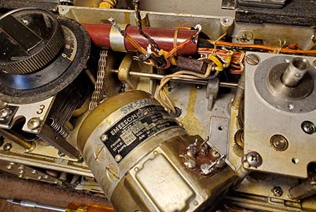
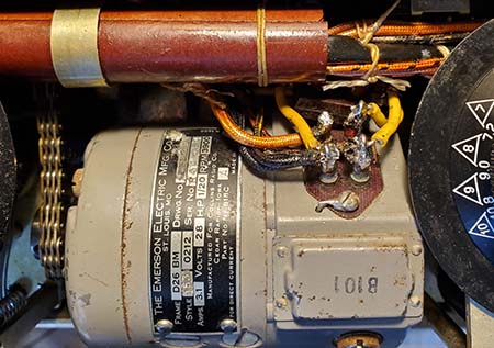
To handle the additional current the +LV transformers are actually two identical transformers that are connected in parallel. When operating transformers in this manner they must be exactly the same,... identical. Also, their connections must be "phased." This means that primary and the secondary windings must be connected so the AC applied and the AC output are in phase in each transformer. This is easy to test ahead of the building and mark the primary and secondary windings so there will be no confusion at assembly time. I only used the parallel transformers because I didn't have a single 400-0-400vac that had enough current capacity for the +LV (+LV and +HV current combined) requirement. If you can find a 500mA rated transformer then going with the single, although large, transformer is much easier. Same reason for the parallel chokes in the +LV supply.

There are some changes that have to be made in the general design that allows for the proper operation of the Plate Current meter since the -HV is connected to +LV. This is basically done by providing a bridge circuit using a 13.4 ohm series load from -HV (negative meter connection) to pin 1 (+LV) and a 6.7 ohm series load from pin 1 (+LV) to pin 9 of U7 (positive meter connection.) This duplicates the circuit used in the original dynamotor. The advantage to this bridge resistor set up is that the Plate Current meter reads accurately regardless of the actual level of +HV and +LV as long as the ratio of +HV to +LV remains approximately 2:1 (actually, the ratio of +750 to +400 is 1.87:1 but the bridge resistor ratio is 2:1.)

Since a minimum of  +750vdc is used for +HV, the filter capacitors can be series-connected 100uf 450wvdc type electrolytics with 510K resistors across each cap to equalize the voltage drop across the series connections. Three capacitors are used resulting in a working voltage of about 1350vdc at a capacitance of about 33uf. Since we are using Pi-filtering, in an "unloaded" condition the +HV could soar to around +1035vdc.The extra "head-room" is protection in case the power supply is operated without a load. The same type of "head-room" is used in the +LV section, where the unloaded voltage could rise to around +600vdc. Using two series-connected 350wvdc electrolytics results in around +700vdc capability. In normal operation, the power supply design is such that the +HV and +LV are actuated with the PTT from the ART-13 which would also be in the powered-up condition thus presenting full load to both the +HV and +LV instantly. However, in some testing situations (or perhaps in an ART-13 failure mode) the power supply might be operated "lightly loaded" (or "unloaded") and this capacitor "hook-up" gives us the necessary head-room to survive this possibility without component damage to the power supply. 

Solid-state microwave oven type diodes can be used in both supplies connected as full-wave rectifiers. These diodes are type NTE517 rated at 15kv PIV. These diodes are relatively expensive at about $8.00 each. The advantage of SS diodes is higher output voltage from the power supplies.

To take advantage of the smaller size and lighter weight possibilities, a 24vdc 13 amp Meanwell Switching Power Supply is used for the +28vdc requirements. This supply can be adjusted up to +27.0vdc maximum which will provide sufficient voltage to operate the filaments, relays and the Autotune. Though the Meanwell PS is RFI quite as a +27.0vdc source for the ART-13, it can cause interference in receivers unless the cable from the power supply to the ART-13 is fully shielded.

NOTE: I used the Meanwell PS for several years without any serious problems. But, I noticed that when operating 630M with the receiver on a loop antenna, I could pick up some noise being generated by the Meanwell PS. HF didn't seem to pick up the noise, just MW. There were other issues with a switching spike on the transmitter output (not audible but seen on a 'scope.) Also, the Meanwell PS would "drop out" on initial power up causing the ART-13 to "chatter" for a few cycles before it would become stable. I eventually rebuilt the Dyna-Sim to use an external +28vdc 25A Lambda linear power supply to correct the problems that were caused by the Meanwell PS. 8-3-20. This power supply also had some issues in that it would "trip its breaker" when PTT was actuated or released. After a ten minute warm-up, the "tripping" was only an occasional nuisance.

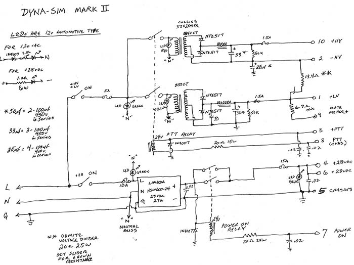
NOTE: Nov. 26, 2020 - I purchased a Lambda 24vdc 25A switching power supply. It's twice as wide as the Meanwell, slightly taller but about the same length. I've installed it onto the Dyna-Sim chassis where the Meanwell had been mounted. All wiring changes that were made for the external power supply were returned to original for internal connections to the new Lambda. A few different "vent holes" had to be cut into the cabinet since the Lambda fan is in a different location than the Meanwell's was and it's larger size required a top vent to allow air intake. The Lambda was mounted using two aluminum brackets rather than mounting the power supply directly onto the chassis. This was to make installation easier and not require major disassembly of the underneath of the Dyna-Sim. The new Lambda easily adjusts up to over +30vdc output. I 
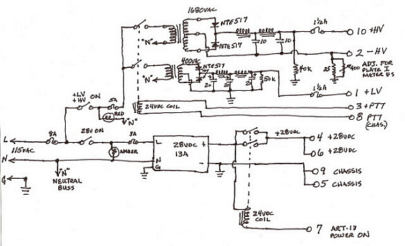
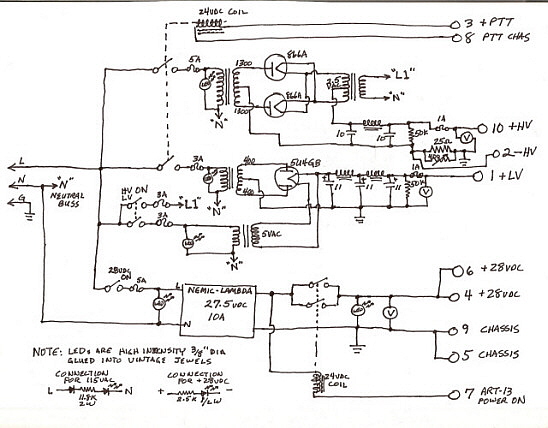
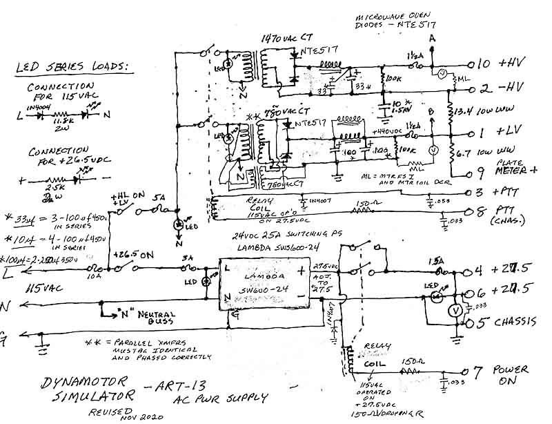
set the voltage output to +27.5vdc. The schematic of the Dyna-Sim shown to the lower right is the latest revision from November 26, 2020.  

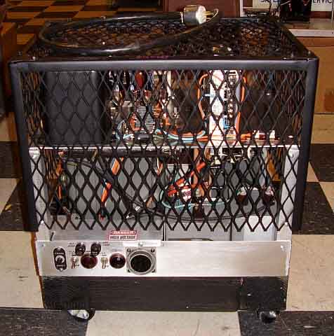
>>>    I decided to build the Dyna-Sim into a BC-348 cabinet. This cabinet had been destroyed by a former owner who drilled out all of the pop rivets that mount the bottom plate which has all of the engagement pins for the shock mount. Rubber feet were installed to take the place of the engagement pins, thus ruining the cabinet for proper use with a BC-348 and FT-154 shock mount. The back of the cabinet had have a wide rectangular opening cut to provide access to the fuses, line cord and the output terminal strip. A round hole was also cut to provide 
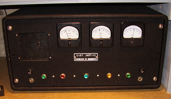
ventilation for the fan in the Meanwell PS. The front panel is made from type of black hard plastic called delrin. Three panel meters are provided to allow constant monitoring of the output voltages during operation. 

As with the "Hommage a le Valve" power supply, the only reason I used three meters is because I found three matching meters in the junk box. Setting up any DC current meter to act as a DC voltage reading meter is quite easy and only involves knowing the meter coil resistance, the meter full scale current requirement and then calculating a series dropping resistor based on the supply voltage to be measured versus the FS voltage scaling desired. For example, if the meter to be used is a 1mA FS DC Current meter and it is going to be used to measure the +400vdc and the FS DC voltage scaling desired is +1000vdc. The DCR of the meter coil in a 1MA FS meter is usually around 50 ohms (but measure it to be exact when actually doing your calculation.) Since the meter is 1mA FS, the total current through the series dropping resistor and the meter will be 1mA. The meter coil resistance is 50 ohms, so E = I/R indicates that the voltage drop across the meter at FS will be .00002vdc. FS DC voltage will be 1000vdc, so 1000 - .00002 = 999.99998 drop required in the series resistor. R=E/I so 999.99998/.001 = 999,999.98 ohms. You might as well use a 1 meg resistor. Dissipation equals I² x R = P or (.001 x .001) x 1,000,000 = 1.0 watt. 2X the dissipation is standard practice and allows the resistor to operate in the middle of its rating. So, a 1 meg ohm 2 watt resistor can be used and the 1mA DC Current meter will read accurately the +400vdc at .4mA on the scale. You can usually alter the actual meter scale so that "MILLIAMPS" is painted over and leave the "DC." If you have suitable "rub-on" lettering, you can add "VOLTS" to complete the meter transformation. To take advantage of the existing meter scale, the +HV meter actually indicates the +700vdc supply measured to -HV rather than measuring to chassis which would indicate +HV plus +LV, or the actual voltage (~ +1100vdc) applied to the 813 and two 811 plates.

Two 24vdc relays are required for the PTT and Power On functions. The junk box turned up a very nice heavy-duty dual relay with 0.25" contacts. The problem was that the coils were for 115vac operation. Since these are solenoid coils, the operation doesn't really change whether AC or DC voltage is used. When using DCV on an ACV rated coil, you will have to significantly reduce the voltage. In testing the relay, it was found that good switching occurs with about 15vdc. A 150 ohm dropping resistor in series with the +27vdc supply provided around +18vdc to the relay and allowed fast, positive switching.

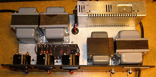
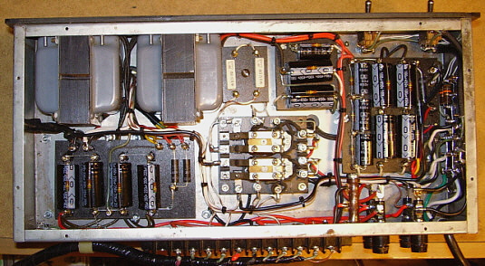
A construction technique employed in the Dyna-Sim is the use of "component boards." The boards were made of 3/16" thick delrin and the terminals were made from 4-40FH brass screws secured with brass nuts. The use of brass allowed soldering directly to the terminal stud. Unfortunately, component boards require a lot of planning for proper layout and routing of the wiring (which is via a harness.) This prolongs the design phase and ends up with the project taking much longer to complete. If you're in a hurry then the use of standard tie points is easier and allows for quick construction. The upside of component boards is that the appearance of the wiring and construction looks like a professional job. See photos below of the finished Dyna-Sim.

+750vdc (+HV) - This is supplied by a 1475vac CT Plate transformer rated at .25A. Since no other windings are on the frame, this transformer is relatively small. Pi-filtered. Actual voltage is close to +900vdc under load. Total +HV is approximately +1300vdc. NOTE: This was changed to a choke input filter for better voltage stability under load. This reduced to voltage to about +700vdc with the resulting total being about +1100vdc. 8-3-20

+400vdc (+LV) - This is supplied by two identical parallel-connected 780vac CT Power Transformers and two identical parallel connected filter chokes. Actual voltage is around +440vdc under load. Total current available is 500mA. Pi-filtered.

+27.0vdc - This is provided by a Meanwell Switching Power Supply rated at 13A. Very small. Apparently not all Meanwell 24vdc power supply maximum voltage outputs are the same. Usually +26.5vdc is the specification for the maximum adjustment but this one adjusts to just over +27vdc. Fully shielded wires for RFI quite operation. NOTE: Too much switching noise appears on output waveform. Rebuilt Dyna-Sim to use an external +28vdc @ 25A Lambda linear power supply. 8-3-20 Rebuilt again 11-26-20 to use a Lambda SWS600-24, a 25A switching PS that could be mounted inside the cabinet.

Relays, Fuses & Meters - Two 24vdc relays are used for PTT and Power On functions. These relays are 115vac coils operated on +28vdc with 150 ohm series resistor. The AC input and all outputs are fused. Three meters allow for constant monitoring of the voltages during operation.

Plate Current Meter Bridge Resistors - This is an original combination WW resistor from a junk DY-17A dynamotor base.

Pilot Lamps - High intensity LEDs with vintage-type jewels are used. Red = +HV, Yellow = +LV, Blue = ART-13 Pwr ON, Green = AC power ON to +28 supply and to +HV & +LV supplies.

Cabinet-Chassis - Derelict BC-348 cabinet with black delrin front panel. The "cool" tags were donated by KØDWC and KE7MFW. Cabinet was painted with VHT Black Wrinkle Finish paint. The chassis is steel. 

NOTE ON CABINET: Since the BC-348 cabinet is aluminum (and the Dyna-Sim panel is delrin) and the case of the ART-13 is aluminum, no protection is provided for magnetic coupling from the non-potted transformers in the power supply. When installing the power supply be sure it is not placed directly next to the right side of the ART-13. Since this is where the ART-13 Audio Module is, very likely magnetic coupling will occur and cause some 60Hz hum to appear on the signal in the VOICE mode.

Read Aug 3, 2020 updates in the section below the schematic. The schematic of the Dyna-Sim is the latest revision from November 26, 2020.
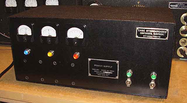

photo above: The Dyna-Sim ART-13 Power Supply in operation


Photo Above - The top of the chassis of the Dyna-Sim ART-13 Power Supply. The two identical transformers on the upper left are the parallel transformers for the +LV supply. To the lower right is the transformer and choke for the +HV supply. The upper right is the +27vdc 13A Meanwell Switching Power Supply. The Meanwell has been replaced with Lambda SWS600-24 which requires double the chassis space in width but length is the same. The component board on top of the chassis has the load resistors for the meters and for the three LEDs for Power On, +LV and +HV. Chassis dimensions are 16.5" x  8" x  3"


Photo Above - Under the chassis upper left are the parallel chokes for the +LV. The left side component board is for +LV diode-filtering. Center is the PTT and Power On relay. Upper center are the relay load resistor board and the auxiliary +HV filter board. Right side is the +HV diode-filtering board and mounted on the side wall of the chassis is the Neutral Buss, AC LED Diode Board. Note the Ohmite resistor mounted vertically next to the fuses. This is the plate meter bridge resistors. 


Schematic of the Dyna-Sim - revised November 26, 2020

This is the latest version of the Dyna-Sim with the Lambda SWS600-24 Switching Power Supply that provides +27.5vdc at 25A. All changes for back emf unloading on the relay coils and additional decoupling capacitors are shown. Additional note,...I didn't use that 10A fuse ahead of the power on switches but the output fuse is 10A, not 15A.

Initial Testing of the Power Supply - After any one of these power supplies is built it will be necessary to perform some tests before actually connecting it to a transmitter. This will require attaching some "hefty" load resistors for the +LV and +HV supplies. The +28vdc doesn't require a load since the Meanwell is voltage regulated and remains constant regardless of the load. With the +28vdc operating check the operation of the two relays that operate the "Power ON" function and the PTT function. This will require using some test leads for the connections to simulate what the ART-13 does in operation. You can use a separate +28vdc bench power supply to actuate the PTT, otherwise, using a test lead connect PTT + (pin 3 U/7) to the +28vdc and ground pin 8 U/7 with a test lead to actuate the PTT.

The +HV and +LV will require calculating a suitable load resistor for each supply. By using the expected voltage as E and the amount of current drawn as I, then E/I=R, which will give you the resistance value for that amount of current to be supplied by either the +HV or the +LV supply. Use I²R=P to calculate the amount of watts the resistor will have to dissipate. You'll find that the load resistors must dissipate around 100 watts, so large wire wound "Ohmite-type" resistors are required. Use good clip leads to connect the load resistors to the output terminals. Apply the power supply AC voltage and actuate the PTT. This will apply AC to the +LV and +HV transformer primaries. Measure both the +HV and +LV to see what the actual voltage "under load" is. Let the power supply run for a few minutes and then deactuate the PTT and turn the power supply off. This checks the most important part of the power supply. Use about 225mA or so for the +LV load current and about 130mA for the +HV load current.

Once these tests have been performed, attach the U/7 connector to the ART-13 and power it up. If you are using the power supply with a known operational ART-13 that is already connected to an antenna, you should be able to do a test of the entire operation of the power supply and see how it works with the transmitter. If you are going to use the power supply to troubleshoot an unknown condition ART-13, then you might be blowing some fuses. That's why fuses are in the circuit - to protect your power supply. Use only the fuse current rating necessary for reliable operation in the fuse values you select. Fuses "blow" because of the relationship of their internal resistance versus the current flow through the fuse. I²R=P and P (watts) is what blows the fuse. The voltage shown on the fuse is the design rating for the fuse structure and type of housing. It's the current change that "blows" the fuse since the circuit voltage and the fuse resistance remain constant (until the fuse "blows.") So the appropriate fuse current rating is just slightly higher than the normal current demand of the circuit being powered.

IMPORTANT NOTE ON THE MEANWELL POWER SUPPLY - I've never experienced any RFI noise problems with the Meanwell switching power supply when used with the ART-13 as the source of +28vdc at 10A. That being said, I've noticed that if the Meanwell is used to power up a receiver, for instance the R-392, fairly noisy operation will result. This situation was experienced when the power connecting wires from the Meanwell power supply to the receiver were unshielded. Although the receiver and the power supply were grounded, the connecting wire for +28vdc was unshielded and could thus radiate some RFI noise. I'm sure that the reason I don't have any receiving noise when using the ART-13 is because the Meanwell power supply is shielded within the homebrew power supply (HB PS) cabinet and -28vdc is grounded to the chassis of the HB PS and the connecting cable from the HB PS to the ART-13 is fully shielded. So, when using the Meanwell on some DC operated gear you may find that if your connecting wires are unshielded you'll have some interference in the equipment or in nearby receivers. However, with a fully shielded cable that is grounded to the chassis and the -28vdc (and the chassis is connected to the house AC ground and/or shack system ground) that interference is eliminated.

UPGRADES to the Dyna-Sim: Aug 3, 2020 - After a successful filtering modification to the Hommage a le Valve power supply, I decided to go ahead and also put some changes into the DynaSim. First was to change the +HV to a choke input filter to reduce the voltage level down to around +700vdc. It had been running over +900vdc. With a C input filter pi-filter, the stability of the +HV voltage was not very good. Running at 150 watts of carrier on the ART-13 would show very prominent voltage drops with voice modulation. Choke input would provide lower +HV that has better stability with varying loads. The total value of C was doubled by paralleling the input C with the output C (total of 66uf capacitance.) The +LV uses a pi-network filter and runs about +440vdc, so that wasn't changed. The actual voltages under load now are +680vdc and +440vdc which results in +1120vdc +HV which is very close to the normal +HV when using a dynamotor. Under voice modulation, virtually no needle movement on the +680vdc meter or the +440vdc meter is noticeable. Positive modulation is improved when observing the ART-13 output on an oscilloscope.

Initial Change to +28vdc Supply - The problem of the Meanwell switching PS required a more significant modification to the design. First was removal of the Meanwell PS. Next, a six double terminal barrier strip was mounted to the chassis top where the Meanwell had been mounted. The 120vac input that had been connected to the Meanwell was now connected to the terminal strip which allowed the Lambda AC input to be connected to the "switched AC" from the Dyna-Sim front panel toggle switch to "power up" the Lambda (model LK351-FMOV-5104-4.) This is a very heavy (~90 lbs.,) rack mounted fully adjustable power supply. It can be adjusted up to 40vdc and has peak current carrying ability of 40A but is nominally rated for 25A continuous. Next, the +28vdc wires from the Power/PTT relay in the Dyna-Sim were changed from 14 gauge wires to 12 gauge wires. Ring lugs were soldered to the ends that connected to the terminal strip and the other ends were soldered to the relay connections. Finally, the AC power input "power cable" of the Lambda was modified to have soldered ring lugs that were connected to the Dyna-Sim terminal strip. The +28vdc 25A Lambda output was connected to the terminal strip using a shielded two conductor (10 gauge wires) cable. The two new cables into the Dyna-Sim were routed through the "vent hole" in the rear of the cabinet that had been for the Meanwell fan air intake. Each new cable is about 28" long which provides enough length to have the Dyna-Sim cabinet to set on top of the Lambda (actually a spacer is used to allow ventilation for the Lambda.)

Not everything about this "upgrade" worked as expected. Although operation was excellent, actually getting into and remaining in operating condition was plagued with regular "shut down" issues. The operation of the ART-13 PTT would repeatedly "trip the breaker" on the Lambda LK351. After a ten minute warm-up, the tripping became much more random and operation then was more-or-less normal. I operated the Dyna-Sim in this manner for three months. However, since the LK351 was such an enormous, 90 pound power supply, I started to look elsewhere for another +28vdc solution.  I was able to purchase a used Lambda SWS600-24 which is a 24vdc 25A switching power supply in late-November 2020. 

Upgrades to the Upgrade - November 26, 2020 - Installation of the Lambda SWS600-24 25A Switching PS - To install the new Lambda power supply, I had to remove the chassis mounted terminal block. Also, some other chassis screws needed to be either removed or relocated to allow the new Lambda PS to install onto the Dyna-Sim chassis. This new Lambda is about twice as wide as the old Meanwell PS was but just about the same length. The height is somewhat increased and is very close to being "too tall" to allow the Dyna-Sim chassis to fit into the cabinet, therefore the need to make sure that the Lambda would set onto the chassis with virtually no additional height. I decided to use two brackets to mount the Lambda to the chassis since this would avoid major "under the chassis" disassembly of the Dyna-Sim. The brackets were made from .062 aluminum and they were attached to the Lambda using 8-32 machine screws after the metric threads were "chased" with a 8-32 tap. The brackets were mounted to the chassis using self-tapping sheet metal screws. The wires that had been connected to the terminal block were now connected to the new Lambda PS terminals.

As a test, I temporarily connected the ART-13A to the Dyna-Sim and it powered the transmitter in both AM and CW with no problems. The waveform looked clean. No shutdowns and no "chattering relays" with power up. CW operation didn't cause any changes in voltages measured on the panel meters. Even operation of the auto-tune didn't cause the +28vdc meter needle to even budge.

Next, I needed to cut new vent holes in the cabinet since the Lambda fan is in a different location from where the Meanwell fan was. One 3" square hole was cut on the right side towards the back for the actual fan exhaust. On the top of the cabinet, two rectangular holes were cut to allow air intake which then flows through the Lambda to keep it cool.

The Lambda fan is pretty noisy and it really goes into "high gear" when powering the ART-13A which is nominally 8 or 9 amps unless the autotune is actuated and then the current goes up to just over 10 amps. When operating the SAAMA ART-13A the "dynamotor simulation" is now complete - it includes the "whine" we all expect to hear when an ART-13A is dynamotor-powered. On the air tested on November 29, 2020 on the 75M Vintage Military Radio Net (as NCO) in operation one and a half hours with no issues. ART-13A was running 120 watts carrier power output that was fully modulated. And yes, the Lambda PS fan could be heard "over the air" so it is pretty loud.

The Dyna-Sim schematic shown above is the latest revision from November 26, 2020.

Dyna-Sim Mark II

NOTE - NEW - "DYNA-SIM MARK II" is in the works: In the works,...a NEW Dyna-Sim for 2021! For some time now, I've been planning another AC power supply to run the ART-13A "Wasp's Nest" which is currently located out in the shop and set up to run on the DY-12 dynamotor which is run by the PP-1104C power supply. In Feb 2021, another ART-13 transmitter showed up, an ATC version. This has made the necessity of a third AC power supply become more than just a "some day I'll do that" project.

I recently used my old Dyna-Sim (Mark I) to repair a fellow ham's ART-13A and the ease to move it around (it's not too big and it's not too heavy) and its "rock solid" operation (now with the Lambda SWS600-24 for the +28vdc and the choke input filtering on the +HV) has convinced me that the Dyna-Sim approach of "stacked" power supplies is the easiest way to achieve an AC power supply that closely matches what the original dynamotor provided for operating voltages and current.

The Dyna-Sim Mark II will be very different compared to the first Mark I version. I'm trying to make "Version II" a much easier to build power supply. No parallel connected transformers or chokes. No meters, just pilot lamps (I've found I rarely look at the meters on the other AC power supplies. The Dyna-Sim Mark I is located on the floor and the meters can't be seen anyway.) The pilot lamps will be the Automotive LED type that are already installed in a finished housing. These operate on 12vdc at 11mA so proper rectification and dropping R for AC line monitoring or a proper dropping R for DC monitoring will be necessary (this won't require using "vintage" jewels, just easily available "new parts.") The plate transformer from a "parts set" Collins 32V-2 will provide around +700vdc at 350mA with choke input filtering. The +400vdc supply has to be capable of at least 500mA current flow (+HV and +LV combined.) I found in my transformer collection a 850vac CT (425-0-425) that is marked that it's rated at 4 amps (that's 3400 watts!) It's slightly larger than the Collins 32V-2 plate transformer so there is some doubt that it actually can supply 4 amps but even if its really only .4 amps, that's enough. I've also located two really heavy-duty chokes for filtering (4.25H at .5A.) I'm going to try to avoid using any component boards for construction since these tend to over-complicate wiring and are really only for appearance.

I ended up with a Lambda HWS600-24 by mistake. I had ordered another SWS600-24 (25A) but was sent the 27 Amp version instead - no extra charge! The HWS version has a smaller "footprint" than the SWS version. HWS is 6.5" x 4.0" x 3.25". I hope it's as RF quiet as the 25A version is. NOTE: I tested this Lambda by using it to power up an ARB receiver using an unshielded power cable. Although the cooling fan for the Lambda is very noisy, there isn't any detectable RF interference from the power supply operation. However, I used it to power up a R-105A/ARR-15 receiver and there was considerable noise in the form of tunable noise spikes in various parts of the HF spectrum. Since the installation in the ART-13 power supply will be shielded, bypassed and use only shielded cables, I doubt there will be any noise problem (other than auditory.)

I'm still collecting parts at the present time - March 2021.  Chassis acquired. It's going to be a tight fit since the chassis is 17" wide but only 10" deep. Everything lays out with enough space.
August 8, 2021 - Back at the new Dyna-Sim Mark II. Extracted the plate transformer out of the "junker" 32V-2 transmitter. It has some rust spots and some missing insulation on one of the primary lead wires but otherwise it's in good physical condition, though it will need to be repainted. Tested the transformer windings (DCR) and it seems okay. Did a layout that included the +LV transformer and choke, the +HV transformer and choke, the two Potter-Brumfield relays and the Lambda 24vdc 27A power supply. There is enough space using the 17" x 10" x 3" chassis. The two relays, the rectifiers and the filter capacitors will mount under the chassis and the "iron" will be on top along with the Lambda PS. All transformers and chokes are the hermetrically-sealed types. Also, tested the Lambda HWS600-24 running the PDR-1 DF Receiver that's out in the shop and that runs on a dynamotor power supply. There are strong "noise spurs" all up and down the lower frequency bands (AM-BC.) The cable to the the PDR-1 isn't shielded and the negative -24vdc wasn't tied to chassis ground of the Lambda PS or to the shop ground. I'm pretty sure all of these new Lambda PS that are made in PRC-China have the switching noise on the outputs. As with the Dyna-Sim I, by using only shielded cables and making sure the Lambda is grounded at the line ground, bypassing the +24vdc to ground with disk capacitors, the -24vdc is tied to PS ground, that all shields tie to chassis ground and the chassis of the Lambda is directly bolted to the PS chassis will shield all of the switching noise. On the original Dyna-Sim, I had an original divider resistor set from a "junker" dynamotor. On the Mark II, I'm going to use a 20 ohm 25W WW Ohmite Voltage Divider resistor. The slider can be set to have 13.4 ohms and 6.6 ohms (13.4 ohms and 6.7 ohms were the stock values.) If the divider is slightly off from 20 ohms, as long as the ratio of 2:1 resistance is maintained, the ART-13 plate current meter will be accurate. The five LED pilot lights are going to be the automotive types that operate on 12vdc so all will require dropping resistors and four of the five that operate on the AC line will also require a 1N4007 rectifier diode. These are new, easily available and mount in a .25" diameter hole. Under the chassis, I'm going to have to use two component boards - one for the +LV rectifier-filter capacitors and one for the +HV rectifier-filter capacitors. Output voltages and transmitter connection will be via an original ART-13 box receptacle to allow using either of the two ART-13 power cables I have (one original and one built-up one.) Fuses are going to be in standard panel mount fuse holders for easy access. I'm planning on mounting carrying handles on each side of the chassis since the finished power supply will be pretty heavy.

Schematic for the Mark II is shown to the right. The circuit is very close to the original Dyna-Sim but minus the meters, minus the parallel iron and a few other things. Most of the changes are mechanical to simplify that aspect of construction.

August 12, 2021 - More testing. The Collins 32V-2 Plate Transformer measures 840vac - 0 - 840vac. Used the "600V" tap on the primary which is the highest DCR. Using the "700V" tap should produce about 950vac each side of CT. Tested the Potter-Brumfield relays which are marked as 24vac coils. Running on 28vdc, the coil draws almost 2 amps. A 20 ohm series resistor reduces the current draw to .775 amps with the operating voltage on the coil then being 22vdc. Since these are rated for AC voltage, to operate on DC, the voltage can be reduced using a series resistor and the operation of the relay remains about the same. I had to do the same thing on the original Dyna-Sim but that was because I was using 115vac coil relays operating on 28vdc. Ordered the automotive LED pilot lamps and the 20 ohm 25W WW voltage divider (Ohmite vitreous enamel coated with exposed winding for a slider.)

So, why isn't this project finished? Design Change,... Mark III will be in the works! Well, here it is Jan, 2022 and the Mark II is in the same unassembled state. I've been having very serious second thoughts about the Lambda HWS600-24 switching power supply. Some of my tests performed using the exact same Lambda that was intended for the Mark II turned up some incredible switching noise levels. Not only pretty intense RFI noise but the screaming velocity fan produces a very loud and definitely unpleasant aural experience. I had wanted to duplicate the DynaSim Mark I but maybe that wasn't such a good idea. The main thought with the Mark I had been reduced size and weight. But, what if that could be achieved in a different way? I had several (lots) of 6.3vac 20amp filament transformers. I had enough transformers to build a +28vdc power supply capable of 20 amps,...more than enough for the ART-13 +28vdc requirements. The advantage would be a linear supply,...no RFI noise,...and no screaming velocity fans,...quiet operation. I'm thinking about bypassing the Mark II version and going directly to the Mark III version. The Mark III version will comprise two power supply chassis,...one for the +28vdc 20A supply and then the stacked +420vdc and +750vdc supplies on another chassis. The two separate supplies are for ease of moving. Certainly the two supplies together would weigh over 100 pounds and require a substantial chassis - probably a steel chassis to support that much weight. This really isn't that "major" of a design change. In looking at the schematic, all remains the same except where the Lambda is shown with its connections, that's where the Linear Power Supply would be connected - essentially five connections. I'm still in the design phase (again,...maybe it should be "the redesign phase) and as any progress is made, I'll report it here.


ART-13 Auto Tune Mechanical Details, Synchronization, Motor Replacement

The Mechanical Stuff

The Autotune Mechanism - The Autotune is made up of four 360º rotation (single turn) modules and one 20 turn module. These modules are driven by a Line Shaft that has worm gears on it that mesh with the drive gears in the five modules. The line shaft is driven by a reversible direction motor that is controlled by a motor drive relay. Additionally, the Channel Selector switch works in conjunction with the motor driven (from module A,) rotating Selector Switch to determine which channel has been selected. Finally, there is a Forward Limit Switch and a Rear Limit Switch that reverse the direction of the motor and provide the stop function by removing a short circuit condition on the 100 ohm motor current resistor (when the cycle is completed, a small "locking" current flows through the motor windings through the 100 ohm resistor.) The two limit switches that basically control the cycle are located on the 20 turn module since its operation requires the longest time to achieve its set point.

Important Note: Do not try to adjust the knobs of the Autotune section while the Locking Bars are tight. Anytime you want to adjust the settings of the individual control, first undo the Locking Bar and then make your adjustment. Then retighten the Locking Bar. If you make adjustments with the Locking Bar tight, you'll upset the presets for that channel and possibly all of the other channels too. You can also place the Channel Switch in MANUAL and let the Autotune cycle. Afterwards you can then manipulate all of the controls with the Locking Bars tight and you won't upset the presets.

As soon as you power-up the +28vdc line to the ART-13 the Autotune will begin to function if the Channel Selector switch position has changed since the last time the transmitter was in operation. The Autotune cycle first runs the five modules to a "zero" position and continues until the Forward Limit Switch is actuated which then reverses the motor direction. In this rotational direction each of the modules will lock in a preset condition determined by where the controls were "preset" for the particular channel selected. After all five controls have locked in position the motor continues to run until the Rear Limit Switch is actuated which stops the motor rotation by placing the current resistor in series with the motor windings. This method of stopping the motor was used to provide enough current to "lock" the motor in position, preventing the controls from being accidentally moved by vibration or other methods. The entire Autotune cycle usually takes about 25 seconds to complete. When completed the PTT line and the Keying relay operation are returned to functionability and the transmitter can be put into operation.

Quick Test - A quick test of the Autotune can be accomplished by just providing +28vdc at about 10 Amps (this is the filament load plus the Autotune load, which is about 1 additional amp while running.) Connect the power supply to pin 4 for the positive and pin 5 for the negative. You should use at least 16 gauge wire, 14 gauge is better. Switch on the power supply and the Autotune should start its cycle. If it doesn't, change the channel. If everything is okay the cycle should complete in 25 seconds and the motor will stop. Change the channel and the cycle should start again and complete in 25 seconds. This quick test only powers the part of the ART-13 circuit that runs the Autotune motor and will show that the Autotune is working. It will probably need lubrication and preset adjustment. 

Lubricating the Autotune Mechanism - The Line Shaft runs in bronze sleeve bearings and in ball bearings at each end. These bearings should be given a drop or two of light weight oil, 10W is good, something like sewing machine oil. Each module is driven by a worm gear that is installed on the Line Shaft. All of these worm gears should be coated lightly with light weight grease using a long handled paint brush. Each of the gears associated with each module can also be lightly coated in the same manner. Use a drop of machine oil on each of the bearings on the rotating gears. Use oil sparingly on the chain drive and don't stand in front of it during operation with the cover off after lubrication - you'll end up with oil all over the front of your shirt! (Yes, I've done it.)

Common Autotune Problems - Since the Autotune cycle controls the PTT line and the Keying relay operation, if there are problems with the Autotune, you won't be able to run the transmitter. Most of the time, the Autotune mechanisms are still in good condition because they were well protected by the front cover which even has felt seals around each opening to keep out dirt and dust. 

If the ART-13 you are inspecting to purchase has been disassembled and the front Autotune cover removed or left off, be very wary of the transmitter. The Autotune is difficult to work on if complete disassembly is required. Look for a transmitter that is complete and shows no indications of having been a "parts set" at some time past.

That being said, the most common problems with the Autotune involve the limit switches. The Forward Limit switch is mounted on the extreme right side-front of the 20 turn module and can easily be hit or bent with careless handling of the transmitter with the front cover off. The Rear Limit switch is a "rocker" type switch that is very, very delicate and if damaged it is difficult to get it to work correctly again. Fortunately, it is further back in the module and a little better protected from damage.  

If the Forward or Rear Limit switches aren't making good contact it will cause the Autotune to operate to "zero" position and then it will just set there with the motor continuing to run. With the Forward switch it is very simple to carefully bend the arm so that the rotating screw-driven actuator arm just opens the switch at the "limit position."

Opening the Forward Limit switch momentarily will reverse the motor relay position and reverse the direction of the motor so that the "preset" operation of the Autotune cycle can proceed. The Rear Limit switch has a spring-loaded contact that relies on a longer flex arm with a fiber button as the mechanical contact. Be careful if you have a mechanical problem with the Rear Limit switch. Very minor adjustments are all that should be required if it doesn't actuate. Bending of the arms should be avoided. Most problems with the Rear Limit switch are caused by contamination or dirt and not the mechanical adjustment of the switch arms.

Synchronization Problems - Sometimes the Autotune presets are not where some of the individual modules end up stopping. Most of the time this is dirt or contamination in the particular module's clutch. Try re-setting the preset and operating the Autotune cycle several times. Usually each time the module will stop closer and closer to the preset point. The operation seems to clean the clutch which results in accurate preset response. Sometimes the selector disks are not in the proper location to allow the pawl to drop into the slot and stop the control. Inspection of the module while in operation can confirm if this is what is happening. To correct, loosen the lock bar and rotate the particular selector disk to a position where the pawl can drop correctly, then tighten the locking bar.

Sometimes one or two modules will always operate to the end limit on a particular channel. Check the springs on the pawls to see if one of the springs is not in its proper slot. Sometimes these springs become caught in the selector disks and will get bent. This is uncommon but it depends on how badly the particular ART-13 was treated in the past.

If you have an insolvable problem with one or more of the modules, they are easy to replace, but you'll have to re-synchronize the other modules to the new module. To remove a module first take the front cover off. Then remove the locking bar and the knob. Remove the knob backing plate and you now have access to the two slotted head screws that mount the upper part of the module. Remove these two screws and the lower Philipp's Head mounting screw. If you are removing the Antenna/Loading modules, you'll have to remove the screws that mount the phone jack bar to these modules. The bar only has to be dismounted and placed slightly out of the way to remove the module. The module engages the worm gear of the main shaft and has a spline drive socket at the rear that drives the particular control. Install the new module and replace the screws in reverse order.

Details on knob and module synchronization follow in the next section.


photo above
: PA Tuning and Loading section of the Autotune. These modules are single turn, 360º rotation, driven by the line shaft. Between the two left-most modules is the motor drive relay. Note how the phone jack bar mounts to these three modules.


photo above: The motor drive for the Autotune. The chain drives the line shaft mounted at the back of the Autotune unit.


photo above: The VFO section of the Autotune. The rightside module is the 20 turn unit. Forward and reverse limit switchs are on the far right.

Synchronizing the Autotune Knobs - If you have to remove the five large knobs you'll find that there is no obvious shaft flat or other indicator of how the knob position relates to the shaft position. Fortunately, all of the controls have mechanical stops at both ends of rotation. First set all of the controls fully CCW (be sure to loosen the locking bars.) Set the knob positions as follows:

A - Set shaft fully CCW and set knob to slightly before (to the right of) the triangle #1. Remember, all of the set screws require a Bristol wrench.

B - Rotate shaft fully CCW. Be sure that the small turns counter is at zero and at the mechanical stop. Then set the large knob to zero.

C - Set shaft fully CCW and set knob in the middle between triangle #1 and triangle #13 (verify that the antenna loading and tuning circuit contacts "make and break" when the knob triangles are exactly on the peak of the triangle. Triangle #5 is a good "test" position for checking knob synchronization.)

D - Set shaft fully CCW to stop and set knob in the middle of the non-scaled portion of the skirt (it will look like the scale upside-down.)

E - Set shaft fully CCW to stop and set to 0 on 100-0 scale

Tighten the locking bars and actuate an Autotune cycle. Since the knobs are already at zero, the knobs shouldn't turn until the forward cycle begins. Confirm that the controls stop correctly. Specifically, B should stop on a triangle, as should C. In fact, C must always be exactly on the peak of the triangle for each stop (once the knob is synchronized to the shaft.) This control also cam-operates some finger contacts that are part of the antenna loading and tuning. If the setting of C is not exactly on the "peak" of the triangle these contacts may not be correctly actuated and the transmitter will not have any output or show any grid current. Remember, it's not the position of the knob C that determines the cam-switch contacts but that the knob position should be synchronized to show the actual operation of the switches. Also, confirm that D stops in the scaled portion of the knob.

Synchronizing the Modules - If you have to replace a module or if you've removed a module for some reason, you'll now have to synchronize the newly installed module to the rest of the Autotune modules. The procedure in the manual is difficult to understand because it references all synchronization to the A module since it isn't adjustable (because it drives the channel selector switch.) Most of the time you're going to have one of the single-turn modules that isn't in sync with the other single-turn modules. To do the synchronizing, you'll need a way to manually move the Line Shaft via the slotted and tapped hole (4-40) on the right-hand side of the Line Shaft. Originally, the spare parts kit contained a crank that was for that purpose but nowadays the cranks are next to impossible to find. Some technicians use a screwdriver or a blade bit installed in a power driver. If you choose this option, you'll have to be very careful not to damage the slot in the Line Shaft.

It's fairly easy to use a power driver (like a Makita) with a blade bit to position the Line Shaft and not damage the slot in the end of the shaft. Just be careful and make sure that the bit fits tight in the slot. You're going to be rotating the Line Shaft in a counterclockwise rotation.

To synchronize any C, D or E module to the A and B modules just remember to consider that all four sync'd modules should be considered as a single module and it is going to be necessary to sync them with the remaining module (that is out of sync.)

You'll have to disable the out of sync module by loosening the cam drum collar set screws and sliding the collar down the shaft. This allows the selector clutch drum to move but not move the cam drum. See which channel the out of sync module is set to by observing the spring and pawl drop. Now rotate the Line Shaft in the counterclockwise direction noting that the springs and pawls all drop simultaneously on the "in sync" modules. When you are one channel before the channel desired stop using the power driver for rotation and switch over to a regular screwdriver. This is to allow the next sequence to proceed slow enough to control. As you approach the correct Line Shaft position, you'll see one spring-pawl slightly lift and then the next channel's spring-pawl drop into place. Stop rotating the Line Shaft at this position. Now check to make sure that the out of sync module is also in the proper channel with the pawl dropped into position. Slide the cam drum collar on the "formerly" out of sync module back up into position and rotate it with your fingers very slowly counterclockwise. You'll feel a point where there is some noticeable resistance to the rotation, which is the drive pin coming into position. Tighten the collar set screws at this point. You may be only able to tighten one of the set screws but this is sufficient until rotation of the Autotune brings the other set screw into position. Test the synchronization by rotating the Line Shaft counterclockwise with the power driver. Each spring-pawl should drop into position simultaneously. No more than a quarter of a turn of the shaft should be necessary for all of the spring-pawls to drop into position - usually it's much closer than that.

Now, do a channel-select Autotune cycle to test that all of the modules are synchronized. Set up the presets on channel one, then proceed to channel two and then check that if returned to channel one, all of the modules select the proper preset. You can now do all of the presets for all of the channels, that is, if your ART-13 is ready to go into operation.

Photo A

Photo A: This shows the A module which drives the rotating Channel Selector switch located behind the module. This switch rotates until it is in the same position as the front panel Channel Selector switch.

Photo B: This is a close up of a single turn module showing the cam drum. This is where part of the pawl drops into when a channel is selected. Also, the front part of the pawl drops into the slot in the channel locking rings on the clutch drum which determines the preset.

Photo C: This close up shows the cam drum collar which must be loosened and dropped down the shaft to disable the drive on an individual module for synchronization. The collar has a stop inside that couples a drive pin from the gear above. The drive pin couples to the collar stop and then, since the collar is set screw coupled to the cam drum shaft, turns it.

Photo B (left)


Photo C (above)

Replacing the Autotune Motor - The motor is generally a reliable unit but all of these motors are now pushing 80 years old. The motor shown in the photos had a field coil to case short. The motor would still run but the field coil short also caused the +28vdc to draw around 15 amps or more. Although some of the +28vdc power sources I've been using lately can supply over 25 amps, I have the +28vdc fused at 10 amps so the fuse would blow when trying to power-up this ART-13. The bottom cover and the front lower cover have to be removed first. Then the DC resistance to chassis can be measured. F2 is +28vdc to the field coil and F1 is ground. F2 to F1 should measure about 17 ohms. I my case, the DCR was 0.00 ohms or a "dead short." Motor replacement was necessary. I tested the replacement for correct DCR before installation.

To remove the old motor, first dismount the locking bar, knob and back plate from Control A. This allows better access to the motor wiring and mounting screws. The wiring consists of four terminals, F1 and F2 (the field coil terminals) along with A1 and A2 (the armature winding terminals.) F1 has only one wire soldered to it but F2 has three wires and two capacitor leads installed. A1 and A2 have one wire each plus one lead from each of the bypass capacitors connected. These must all be unsoldered from the terminals. Be sure to mark the wires for proper reconnection. The bypass capacitors also have other wires soldered to their leads so they can't be totally removed, just disconnected from the motor terminals (be sure to mark caps for correct reconnection, the wires on the caps are routed through the chassis for motor direction control.) Once the wires and capacitors are off the terminals, then the motor mounting screws can be removed (four screws, usually.) The motor can be moved back on the left side and out on the right side to allow derailing the chain. Now the motor can be removed. Sometimes the left-rear screw won't be installed. Some repair techs didn't want to do the extra work to install this screw so it might be found missing. Although the ART-13 isn't airborne anymore, this screw should still be installed (it's not that difficult to do.)

Installing the replacement motor will require placing the motor in the motor-bay at an angle with the left side going in first so the chain can be placed back on the motor sprocket. Then mount the chain to the motor sprocket. Next, thread-in the three mounting screws leaving out the left-rear screw. Make sure the chain is properly engaged in the sprockets and make sure that the chain tension has some slack - it should be somewhat moveable to allow access to the left-rear screw hole. Using long needle nose pliers insert the remaining screw in position and thread it in using a long thin screw driver (working past the chain) but don't tighten yet. Position the motor for slightly loose chain tension and then tighten the four screws. Then, the wires and capacitors are soldered back to the correct terminals. NOTE: The motor I installed had "barrel terminals" that required making a securing loop out of 16ga TC to clamp the wires before soldering. When completed, double-check the screws, the chain tension and the wiring. Lube as necessary (use minimal amount of lube.)

With +28vdc connected just to pin 4 of U7 and -28vdc/ground connected to pin 5, switch on the +28vdc and the motor should run until the Autotune cycle is complete (don't switch ON the transmitter - motor power is directly connected.) Select another channel and allow the Autotune cycle to complete. Check the current draw, it should be about 2 amps just running the motor and about 5 amps total on the +28vdc line connected to pin 4 of U7 when fully assembled. Install the back plate, the knob and locking bar for control A. Reinstall the bottom cover and the lower front cover. Total current of the completely assembled and operational ART-13 will be about 8 amps on the +28vdc line and just a little over 10 amps when running the Autotune.

1


Motor with wiring disconnected - old motor

2

Note the wires connected to the bypass capacitors leads, these wires are for motor direction control

3

Motor right side out to derail chain - old motor. The new motor goes in the same way, that is, left-side goes in first to allow installing the chain.
 

4

Installation complete. Note this motor hasn't been MFP'd and it has a different tag. Also the barrel terminals complicated wire installation and required loop soldering


ART-13 - Refurbishing the Cosmetics

Reconditioning the Knobs, Dials, Locking Bars and Stop Plates The five large knobs are bakelite with a brass hub. The set screws require a Bristol wrench to loosen. These large knobs project out somewhat and therefore many times they are found chipped. If the knob is chipped, an original must be found to replace it. These large knobs sometimes are found with the white fill paint partially missing and when cleaning is attempted, more of the white fill paint falls off. These knobs are easy to recondition by first removing them and then soaking them in a hot soapy water bath for about one hour. Use a fairly stiff, brass bristle brush (toothbrush size) and be sure that the brush bristles are very straight like a new brush. Brush away towards the edge of the knob to clean the flutes. Don't be real aggressive but go around the fluted section of the knob twice with the brass brush to remove all of the finger grunge. Clean the skirt of the knob with a regular toothbrush. You'll probably find that most of the white fill paint will be removed in this cleaning. Dry the knobs and they will be ready for a new fill paint. 

 Don't use "White" paint or lacquer-stik for the fill. This will be way, way too bright and will look terrible. Use Artist's Acrylic paint that is available from most Hobby or Art Stores. Mix white, light brown (raw sienna) and just a little black. You're trying to get a color that looks like a manila folder,...kind of beige. Though it looks too dark when you're mixing it, when you put it on a black bakelite knob, it will look aged white. Paint the entire skirt of the knob and give the paint about one minute to set. >>>

>>> Next, use damped paper towel pieces that are about two inches square and folded to wipe of the excess paint. Use Glass Plus to damped the paper towel sections as this removes the paint much better than water. Do a small section and then discard the towel - do not try to wipe more of the paint with the same towel as you'll just spread the paint around instead of removing it. Each wipe use a new damp paper towel. As you get nearly all of the paint off, you'll notice the nomenclature looks really great. Now, be careful and just use a very light touch to remove the remaining paint. Normally, I have to do this application twice to get the knob to look first-class and original. You don't have to wait to apply the second fill. Once the knob is finished, set it aside and let the fill paint dry overnight before reinstalling the knob.

The smaller switch knobs have an index line that has the white fill paint. Recondition these knobs using the same procedure as the larger knobs.

The locking bars and locking bar stop plates are often chipped and might have some corrosion. They are very easy to repaint. I first strip the old paint. You will then see all of the defects that were under the paint. Corrosion is common but can easily be removed with 400 grit aluminum oxide paper. Buff with 0000 steel wool. You don't need a primer but be sure to wash the pieces using lacquer thinner before painting. Mount the locking bars on a piece of cardboard so the paint won't get on the back of the bar or on the threaded shaft. I use nitrocellulose black lacquer and apply several coats to the locking bars. The stop plates only need a couple of coats. Let the paint dry overnight and then use lacquer rubbing compound to smooth the finish and then buff. The locking bars and stop plates will look original.

Reconditioning the Front Panel and Cabinet Paint - Since the front panel nomenclature is silk-screened, a total repaint of the front panel sections is not possible. Instead you'll have to use the "touch-up" method. I use Artist's Acrylic "Mars Black" paint in a tube. This color is very close to the original black wrinkle finish on the ART-13. If dealing with the normal dings, flakes and scratches, the paint can be used from the tube and applied with a Q-tip. Rolling the Q-tip will impart a texture to the touch-up that looks close to the wrinkle finish. This paint does dry flat with no gloss. On small areas this usually isn't a problem. 

For larger areas you'll have to use VHT Hi-Temp Black Wrinkle Finish (available at O'Reilly stores) applied thickly with a brush. Spray some of the paint into a small cup and then use a brush to paint two fairly thick coats to the area. Let the paint set for a couple of minutes and then use a heat gun to "force" the wrinkle. Don't use too much heat or the paint will "gloss" and not match as well.

It's also possible to "touch up" using thinned nitrocellulose lacquer using a brush. Once all of the chips and scrapes are covered then use 10W oil (like "3 in 1" oil) on a cotton pad and rub the entire panel area with oil. The touch-ups will blend into the oil-reconditioned wrinkle finish and seem to disappear. However, if the touch-up area is too large then it will show as a "glossy area." Remember though, when the military reconditioned panels and cabinets, many times they just "touched up" using gloss black lacquer. We've all seen it on original gear, so don't be too concerned that some gloss touch-ups show.>>>

>>> Large areas such at the top lid can be conditioned by using an Acrylic "wash." This is a very thin mix of Mars Black and water. The mix should be about as thin as water but still have some paint in it. This mixture can be brushed on the top lid and the excess water "dabbed off" with a cloth - don't use paper towels as they leave lint and small pieces of paper towel behind in the paint. A cloth towel works best. When dry, the top lid will look even with no chips or scratches showing. It will be "flat" and not glossy but it will look better than a scratched up lid.  

Another method is to use thinned nitrocellulose black lacquer applied with a flat cotton pad. Use several cotton pads and saturate them with the thinned lacquer then rub down the entire lid. Be sure to wear nitrile gloves when handling the saturated pads. Since the lacquer is so thin, it covers a lot of area and dries rapidly. When finished the wrinkle finish will look in good condition and original. Be sure you've touched-up all of the nicks and scratches with lacquer before doing this thinned-lacquer rub down.

It is possible to use the VHT Hi-Temp BWF on many of the panels that comprise the cabinet but matching becomes a problem. Wherever there is silk-screening, the spray paint can't be used (except for touch-up.) Whether you can use the spray wrinkle finish to paint the lid or some of the panels will depend on the overall condition of the front panels. Be aware the painting the top lid is a very large area and very, very difficult to paint with wrinkle finish and not have "stripes" - areas that show the spray pattern. Try to spray at least four heavy coats with each coat applied at a different angles. This is the best way to avoid the "stripes." After the new paint has set for about a week, you can install the lid.

CONTINUE TO PART 3


ART-13 Part 1                        ART-13 Part 4                     Return to Home Index


Radio Boulevard
Western Historic Radio Museum

 Vintage Radio Communication Equipment Rebuilding & Restoration Articles,

 Vintage Radio History and WHRM Radio Photo Galleries

1909 - 1969

- 60 years of Radio Technology -


This website created and maintained by: Henry Rogers - Radio Boulevard, Western Historic Radio Museum © 1997/2023