|
A Quick Reference Guide to the Standard Versions |
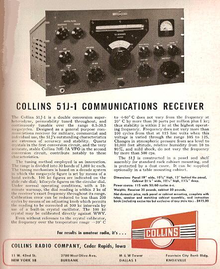
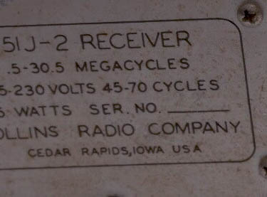
51J-1 - 1947? but probably late-1948
up to early-1950
- Officially available in 1949 but perhaps supplied to the Signal Corps
and a few other commercial users somewhat earlier. Collins (well,...the
CCA) says the receivers were "available in 1945" but, if true, this must
have been in prototype-form when the design was nearing completion. The
basic electronic design concept is certainly obvious in the 1947 75A-1
ham receiver, so it might be possible that the general coverage 51J was
concurrently available with the 75A-1 although the sparse quantity of
51J-1 receivers seen today indicates that very few were produced
(usually the 51J-2 is seen much more often.) Most sources indicate 1949
as the date of availability to the civilian commercial market and this
is when advertising first appears and probably when most of the
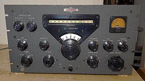
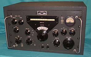
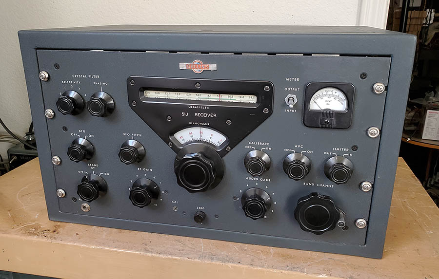
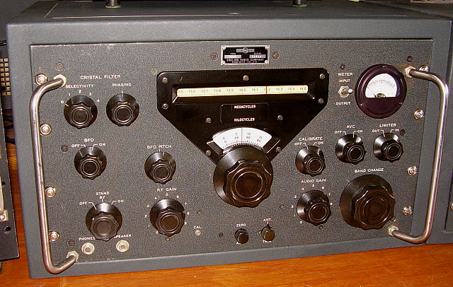
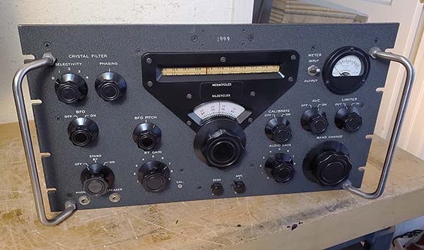
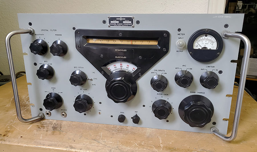
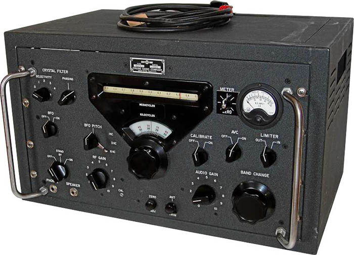
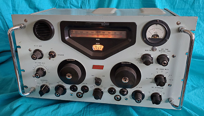
production took place. When a complete and
original 51J model is found it will be equipped with an illuminated
amber scale S-meter, the Collins "winged emblem",
a metal
dial bezel painted satin-black with "51J RECEIVER" silk-screened
in white above the kilocycle dial,
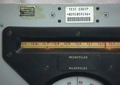
the 70E-7A PTO, the megacycle dial featured green highlighted amateur bands,
"100 KC CRYSTAL"
nomenclature was used for the Calibration Oscillator switch only on the
prototypes, "CALIBRATE" replaced "100 KC CRYSTAL" on panel nomenclature
on all production receivers, the bottom of
chassis had a small cover for the RF sections only with the rest of the
chassis bottom uncovered, no grab handles were used, no skirt was on
Megacycle Change knob but it did feature a crank to ease band changing,
a single phone jack on front panel and the circuit used 16 tubes. The
antenna input impedance was fixed at 300 ohms nominal Z with no Antenna
Trim control used. Each Antenna coil had a primary winding on the J-1
and J-2 receivers. Production level was very low, estimates are less
than 1000 receivers were built (including R-381/URR versions.) The 51J-1
I have has crystals installed (all ten) that are dated 12-49 and the
serial number appears to be 652. Unfortunately, of the surviving 51J-1 receivers I've seen,
ALL
examples had at least several electronic modifications and most had many extensive
physical modifications.
Unfortunately, almost all of the 51J-1 examples I've seen had been
destructively modified in past attempts to "upgrade" the receiver and
usually the destruction was beyond any restoration.
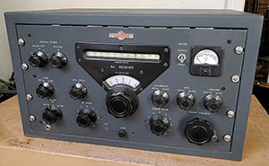
51J-2 -
1950 - The 51J-2 models had essentially the same
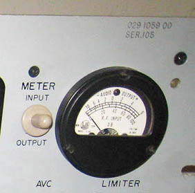
characteristics as the J-1 with these following exceptions; the meter was changed to a Carrier Level/Audio
Output Level meter with
appropriate scaling but meter was still the square front bakelite
housing model with illumination. A switch was added to the meter circuit
to allow measuring either carrier level or audio output, marked "METER -
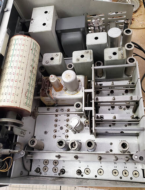
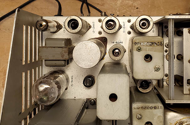
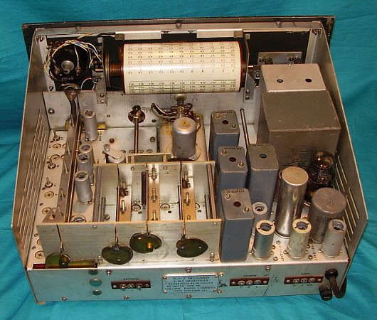
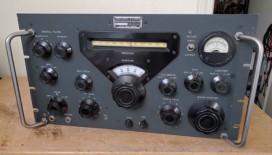
INPUT - OUTPUT." Beginning with 51J-2 serial number 501, the IF
transformers were moved further back towards the rear of the chassis.
This required moving the three 12AX7 tubes to the left (viewed from the
front) and moving the
6AQ5 tube next to the 5V4 rectifier. The AC fuse was moved from the top
of the chassis near the 5V4 to the rear chassis apron near the AC power
cable. All subsequent 51J receivers have
this same tube-chassis layout. It might be possible that the green
highlighted amateur bands were removed from the megacycle drum dial but
this is more likely the result of a recent replacement (R-388) drum
being installed. A few examples have 70E-15 PTOs installed. Production level of 51J-2 receivers was well over 2000 receivers (2233 highest serial
number seen.) Very few of the 51J-2 receivers have survived
in totally original condition. All
examples found seem to be modified in some manner but generally not as
extensively as the J-1.
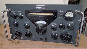
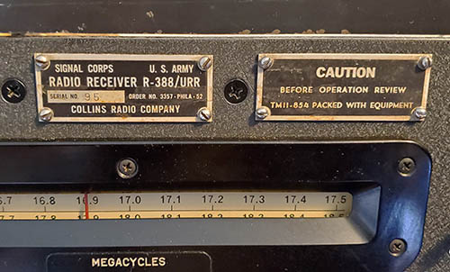
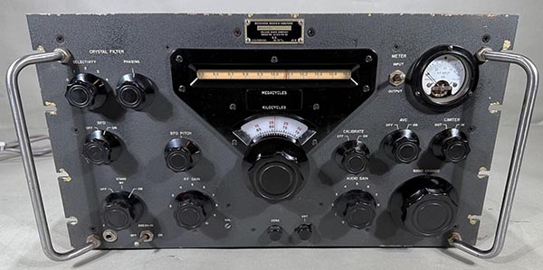
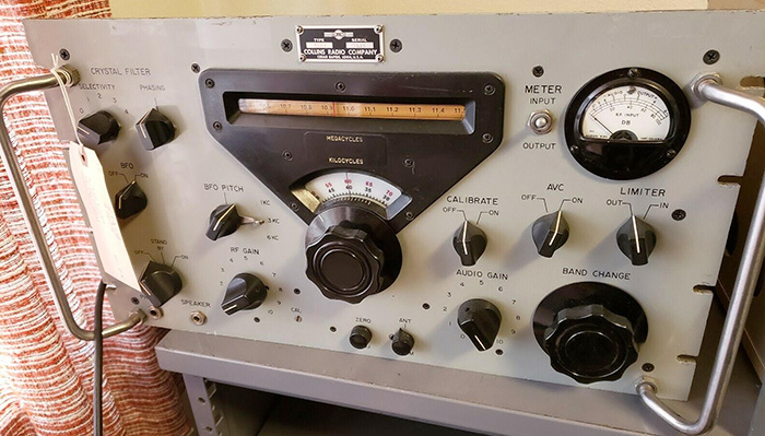
R-388/URR
- late-1950 through 1962 - This is the military version 51J receiver that
featured major changes to the original 51J receiver design. The
antenna input impedance changed from fixed 300 Z ohms to low-Z 50 ohms adjustable by
eliminating the primary winding on the antenna coils and adding an
antenna trimmer capacitor with front panel control. The dial bezel was
changed to a black bakelite piece and "51J RECEIVER" nomenclature
eliminated, the megacycle dial drum no longer had the green
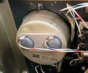
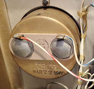
highlighted amateur bands, the carrier level meter was now a non-illuminated, sealed
unit made by Burlington Company (field replacement meters made by Marion
Electric and other companies, DeJur and Simpson are often found as
original installations,) audio
outputs on the front panel allowed for phone (4Z) or speaker (600Z)
connections (pre-1953,) grab handles were now installed on the front
panel, a skirted-knob used for megacycle change, an 0A2 voltage
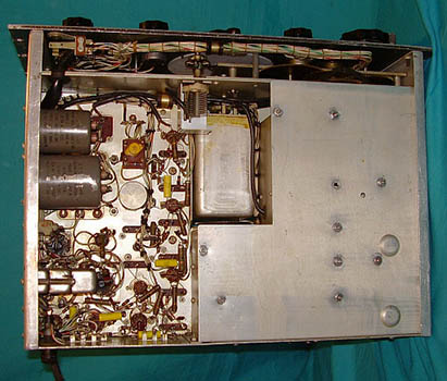
regulator tube was installed, the entire bottom of receiver chassis was
now protected with a slide-in aluminum bottom cover, the
side panels are made of steel and finished with gold color cadmium-based
chemical treatment, the schematic was usually applied to the inside of
the top cover, all
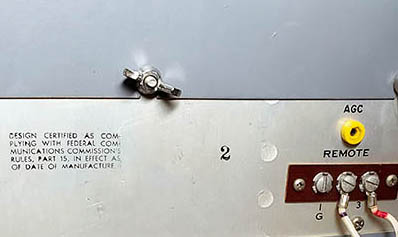
receivers were MFP-coated (very late contract versions were
not MFP'd - 1957 and 1962 contracts,) remote standby or Break-in now required +12vdc to be
applied to a relay via rear terminals. All R-388 receivers used the new
but problematic 70E-15 PTO which added the PTO buffer output tube. This PTO was cylindrical
in shape and has two tubes. All R-388 PTOs are identified with a "M" as a prefix for the
serial number. An
SO-239 connector on rear chassis, "IF OUTPUT," was provided for driving RTTY TUs and other
data devices. 1953 and later receivers have a "Break-in" on-off switch
added to the front panel in the same location as the SPEAKER jack which
was removed. Diode Load and AVC pin jacks are added to the rear chassis
on last of production (1957 and 1962 contracts.) The R-388 was supplied to Army Signal Corps at various times
from 1950 up into the early 1960s. Most (all?) USN R-388 receivers are
considered as AN/URR-23-A but data plate has "R-388/URR" as the
receiver ID (on a USN data plate.) At least 11,000 R-388s were produced (as indicated by PTO
serial numbers.)
Finding all-original, complete and unmodified R-388 receivers is
becoming more and more of a rare occurrence. Many of the R-388s found
today suffer from
incompetent workmanship that seems to have been perpetrated ever since
the receivers became easily available and reasonably priced on the surplus market and from
other sources. But, even now in 2023, finding an "all original,
unmolested" example
is still not impossibly difficult.
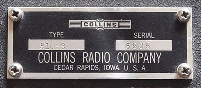
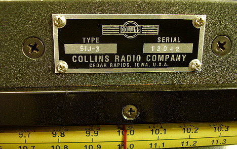
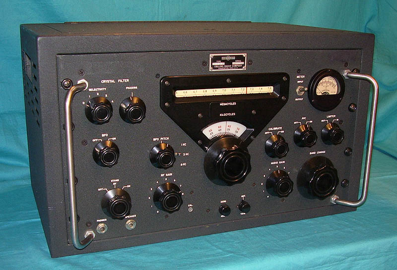
51J-3 - 1951 through late-1953
- The 51J-3 is electronically identical to the R-388/URR and, if an ID tag
is present, it will
show that the receiver is a 51J-3
rather than R-388/URR. However, there is increasing evidence that many 51J-3
receivers were sold without ID tags and used the Collins production
ink-stamped number on the front panel as the serial number. As far as
the circuit and the components used, the civilian 51J-3 receivers are exactly the same as the
R-388/URR. Even the 51J-3 chassis was MFP coated. But, the 51J-3 receiver's
PTO will have a serial number without a letter prefix or suffix, just a
number. It could be possible that the very last of 51J-3 production receivers
might have a "C.R." suffix
on the PTO serial number but the majority of J-3 PTOs don't have SN
prefixes or suffixes. 51J-3 receivers were sometimes installed in a Collins
51J cabinet. 51J-3 receivers won't have any military inspection stamps. Check for Signal Corps acceptance
stamps or other mil-stamps for confirmation. Navy stamps indicate the receiver is the AN/URR-23-A but it would have
been tagged as "R-388/URR" on a Navy data plate (some 51J-3
components like the Break-in relay or the CL meter might have
pre-stocking inspection "anchor" stamps.) 51J-3 serial numbers in the 12000 range
indicate that the data plate is a reproduction and calls into question
the authenticity of the receiver as a true 51J-3. While many "radiophiles"
consider the R-388 is a 51J-3 (electronically they are identical) the subtle
physical differences are very apparent
to Collins enthusiasts. Authentic civilian 51J-3 receivers are scarce
with a production estimate of 1500 to 2500 receivers built.
But, the 51J-3 receivers that were sent out without data plates had no
overt identification (actually, no identification at all) so it's
possible that many 51J-3 receivers might be misidentified as a "tag-less
R-388" receiver.
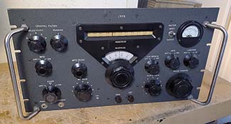
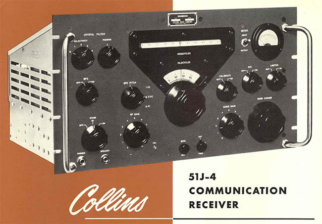
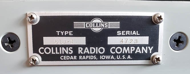
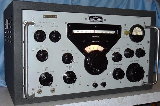
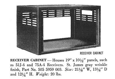
51J-4 - 1954 through 1964
- Civilian, Commercial, Military versions are all the same with the
receiver itself being very similar to the R-388 with the following
exceptions. The 51J-4
added three mechanical filters to the IF by installing the Collins
354A-1 Mechanical Filter Kit into the R-388/51J-3 chassis. Examine the 51J-4 chassis and
it will be seen that the chassis is punched for the standard IF strip of
the R-388 but that a mechanical filter assembly package has been
installed which converts the receiver to a 51J-4. The front panels were
also changed to add 1KC, 3KC and 6KC nomenclature for the mechanical filter selector
switch lever which is located behind the BFO knob. The MF assembly adds an
additional IF amplifier tube bringing the tube total to 19. All 51J-4
receivers have a 70E-15 PTOs with "CR" as a suffix for the
PTO serial number. Majority of
production receivers have St. James Gray wrinkle finish front panels
with white silk-screened nomenclature. A small quantity of 51J-4
receivers were produced with
front panels painted light-gray smooth finish with black nomenclature,
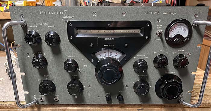
possibly built for laboratory or test facility users. Some 51J-4
light-gray panel receivers are marked "Beckman - Receiver Model 7700" or
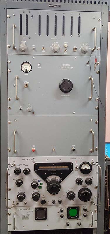
sometimes "Beckman/Berkeley." The Beckman/Berkeley receivers were a
component of a Frequency Measuring System that was a rack with several
other components that functioned with the Model 7700/51J-4. The
light-gray panel 51J-4 receivers are sometimes found with a variety of
Collins-type knobs installed.
51J-4 receivers
are not usually MFP coated. AVC and Diode Load pin jacks are on
the rear chassis. IF Gain control is on later receivers and is mounted
on upper chassis between MF assembly and power transformer. "FCC Part 15" information is silk-screened on the rear of
the chassis on later production receivers. When supplied to the military as the
R-388A/URR or R-388B/URR it's possible that the ID plate had "51J-4"
stamped on it. Serial numbers go up to about 7500. 51J-4 receivers with
serial numbers higher than 7000 are typically found with two difference
sizes of "S-line" knobs and sometimes slightly smaller KC/MC knobs. Good examples of "all original and complete" 51J-4
receivers are still very easy to find but, of course, "good ones" will
be expensive. There are several J-4 variations that
might be considered rare or scarce when compared to the standard J-4.
R-388A/URR and R-388B/URR -
With this designation, these receivers should have been Signal Corps receivers.
These are versions of the 51J-4 but it's unknown if the data plate actually
identified the receiver as a
"R-388A/URR." Same with
the R-388B. At this time, no examples of a receiver identified by the
data plate as "R-388A/URR" are known to exist (navy-radio.com also
indicates the lack of any known examples.) The designation is shown as
"R-388A/URR" in Federal Procurement Books. It could be that
this was just an identification for ordering the 51J-4 receiver and the
receivers shipped from Collins may have
actually had the "51J-4" designation on
the ID tag (or maybe no data plate at all.) Since the R-388A/URR was shown in Federal Procurement Books
as a purchasable receiver (purchase price was about $1200,) the
implication would be that it was a new receiver. As for military
conversions using the Collins 354A-1 Mechanical Filter Kit, there
doesn't seem to be very much evidence that this conversion was performed
in military depots. The common use of "R-388A" to describe a R-388 with
the 354A-1 installation is of radio amateur origin and not an official
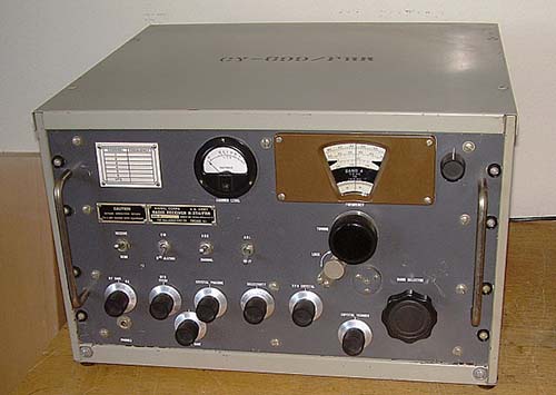
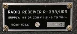
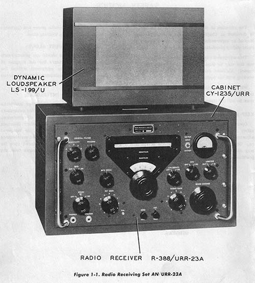
designation. AN/URR-23 and
AN/URR-23-A - These are U. S. Navy designations for the 51J-2
and 51J-3 installed in a Collins cabinet designated as CY-1235/U
with Collins speaker designated as LS-199/U. According to the USN manual
for the AN/URR-23-A, the receiver IS a R-388/URR and this is
shown many times throughout the manual.
It's possible that the AN/URR-23-A identification was on the data plate
that was mounted on the CY-1235/U cabinet. The LS-199/U loudspeaker also
had a data plate installed.
The contract was issued for the AN/URR-23-A on June 22, 1951,
NObsr-52527. There was another 1960 USN contract, NObsr-81258.
R-381/URR and R-381A/URR - These are Signal Corps
designations for the 51J-1 and 51J-2. These receivers don't have the
Collins Winged Emblem but have typical mil-style data plate installed.
|
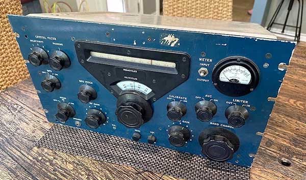
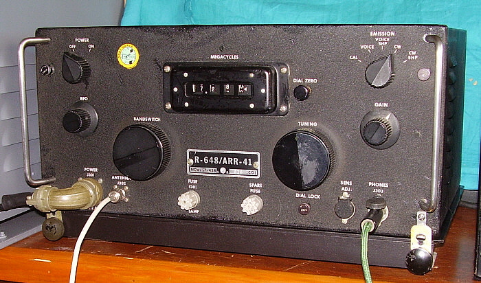
Raytheon modified 51J-3
receivers for the USAF and USMC designated AF-30 or R-645
photo from: eBay |
AF-30 or R-645 -
Special modified version of the 51J-3 used for ionospheric backscatter
research. Modified by Raytheon for the USAF or USMC. Has a blue panel
and no grab handles. Supposedly a very small quantity of only seven
modified receivers were produced. Several photos
on navy-radio.com
Since these receivers were sold to Raytheon, a commercial
electronics manufacturer (who did a lot of military contracts
themselves,) as far as Collins was concerned, they weren't
selling the receivers on a military contract. The AF-30/R-645 receiver is not
a R-388 since those receivers were on military
contracts for the Army and the Navy. Because of the civilian purchase by
Raytheon, Collins installed the civilian 70E-15 type of
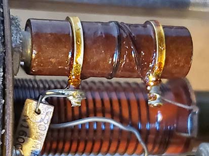
PTO. Note that the PTO serial number doesn't have a prefix or suffix
letter, only the number 727. Only R-388 receivers have the "M" prefix PTOs
(however, the very last contracts of R-388 receiver don't have the
"M" PTO installed - 1957 and 1962 contracts.)
Collins Mfg. SN on this receiver is 3803, stamped on the rear
chassis. |
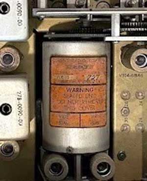
Civilian 70E-15 PTO
installed in the AF-30/R-645
photo from: eBay |
Light-Gray Panel 51J-4 - The
most often heard reason for the light-gray panel 51J-4 were that they
were for use in laboratories or in test facilities. Some Light-Gray
Panel 51J-4s were used in Collins "in-house" labs and these
receivers will have an asset number engraved in the upper right corner
of the front panel. Some Collins Lab receivers have a stick-on paper tag
with the asset number and a bar-code.
But, did Collins supply light-gray panels to other end-user
laboratories? So far, there aren't any indications of light-gray panel
51J-4 used by other companies. However, see Receiver Model 7700 next,...although Beckman made their
own front panels for the Model 7700. Did Collins ever advertise the light-gray panels as an option? I don't think so.
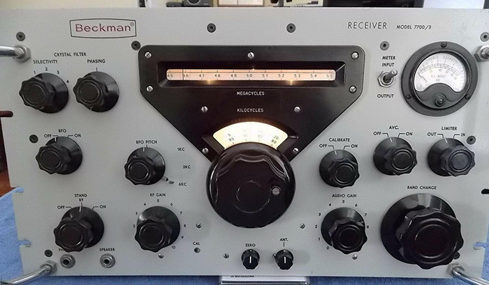
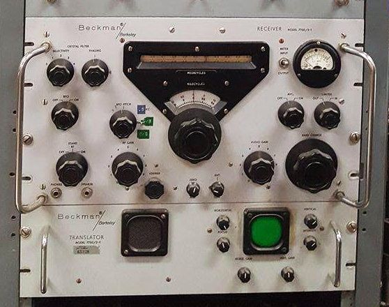
Receiver Model 7700
- This identification is on the Beckman-versions of the 51J-4 with
light-gray, smooth-finish painted front panel. One Beckman/Berkeley
51J-4 has been found with a greenish-gray wrinkle finish panel with
identification as Model 7700/3. Various "/xx" suffix to most Model IDs,
e.g., Model 7700/2-1. Some of the Model 7700 receivers were components
of a Beckman Frequency Measuring System. The Model 7700 receivers had several
(actually lots of) modifications incorporated into the circuitry so they
could function as needed with the other Beckman equipment. Beckman did
all of the modifications to the receivers and made the panels themselves. It seems
probable that Beckman purchased standard 51J-4 receivers from Collins
and then incorporated all of the modifications themselves including the
new light-gray front panel with Beckman logos.
Gloss-Black Panel 51J-4 - Two are
shown on navy-radio.com. One is in good shape having been restored, the
other is in rough condition with modifications. Another original
condition one showed up on
an Antique Radio Internet forum. The black panel was a replacement panel in black glossy finish and the top
and bottom corners of the panel were
notched and the grab handles were mounted low on the panel and had
ejector buttons. There are no phone jacks on the front panel. There are two fuse
mounts above the Crystal Filter controls. The nomenclature for the
Crystal Filter was relocated to below the controls. There is a green
indicator lamp by the "ON" nomenclature of the power switch.
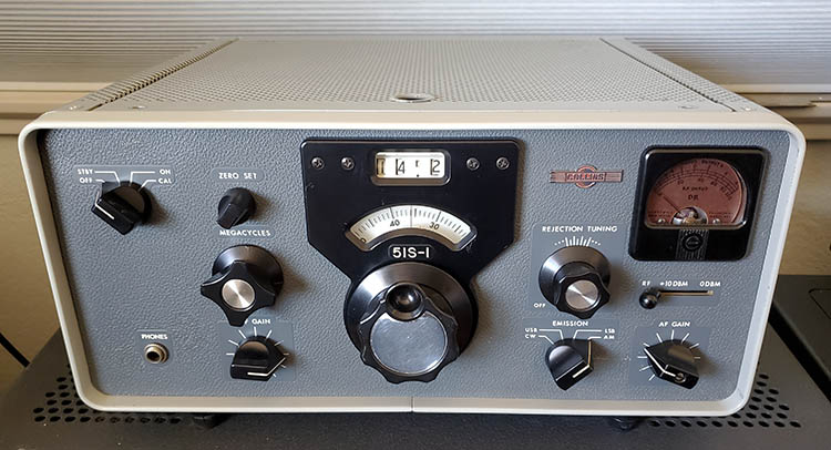
Speculation was that it was the forerunner to the LTV-G133F, a modified
51S-1, for airborne intelligence use. Several photos on
navy-radio.com
NOTE: Mar 2023 - One of these
variations of the 51J-4 has been found with a black wrinkle finish front
panel. The receiver appears to be a R-388 with similar modifications
that the gloss black 51J-4 versions had but without a 354A-1 mechanical
filter kit. This receiver has been modified over the years and many
parts are missing so authenticity is difficult to establish (just
examining photographs.)
|