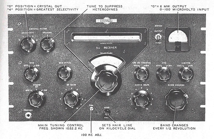
|
The 70E-15
PTO
The R-388 "M" version
versus the 51J-4 "C.R." version
70E-15
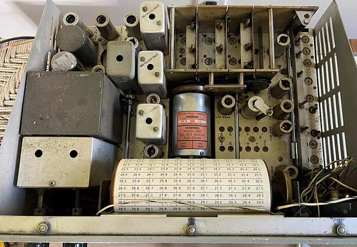
PTO Calibration Procedure - The R-388 and the 51J-3 were the first receivers to use the
new 70E-15 PTO starting in late-1950. Over the years, the 70E-15
has developed a well-deserved reputation of being difficult,
sometimes impossible, to calibrate. To calibrate the 70E-15 PTO
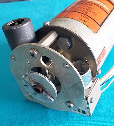
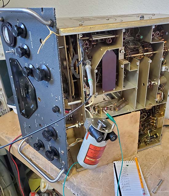
requires that it be dismounted from the receiver but the wires left
connected so the receiver can power the PTO. This required a
fairly involved process of partial receiver disassembly, just to
gain access to the front of the PTO in order to remove the hex
screw-plug that covers the calibration trimmer access hole. The
difficult receiver disassembly was a deliberate part of the
receiver's mechanical design that was intended to prevent untrained personnel
from having easy access to casually adjust the PTO's precision
calibration (with the 51J-1 and 51J-2 PTO, the 70E-7A, the calibration
trimmer was easily accessed on top of the PTO body with no
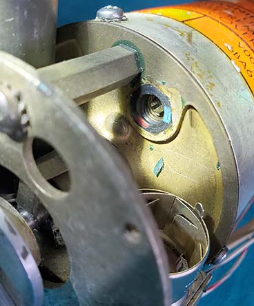
disassembly required other than removing one small cover.) As a further preventative measure against tampering
with the 70E-15 PTO calibration, the adjustment trimmer had a locking
collar that required a special tool to "unlock." The laborious procedure
and special tools necessary to access the 70E-15 PTO
meant that only trained technicians that had a valid reason
would even consider performing the work necessary for a PTO
calibration.
The "M" version versus the
"CR" version - Nowadays, an "as found"
70E-15 "M" version,...that is,...the type only found in the
early R-388 receivers (those built from 1950 up to about 1955,)
will virtually never meet its accuracy specification
due to excessive end-point error that usually can't be corrected with
the L002 trimmer adjustment provided. It was thought that the type or mix of ferrite used for the
PTO core had aging problems that didn't show up immediately.
However, the L002 L-trimmer was provided to compensate for
normal
"aging" changes that happened to all of the Collins PTOs.
But, for some reason, it seemed that the 70E-15"M" PTO changed
a lot
more than expected. Just how long did it take for the
calibration end-point errors to develop? It's very likely that the
70E-15 "M" EPE problems really developed into serious
problems fairly quickly, certainly within a few years. During
the mid-1950s, Collins would slightly modify early 70E-15 PTOs
that were sent back for repair but couldn't be calibrated. The
modification was to remove one turn from the internal trimmer
coil, L002. This allowed the early PTOs to calibrate to
specifications. However, it was only a temporary "fix" and Collins improved the 70E-15 PTO
around the time that the 51J-4 was introduced in 1954. ALL 51J-4
receivers were equipped
with a 70E-15C.R. PTO. These "C.R."
versions rarely have an
uncorrectable EPE and usually can easily be calibrated just
using the L002 L-trimmer provided. Although the schematic never
changed for the 70E-15 PTO, obviously something inside was
changed to make the "C.R." versions maintain their calibration
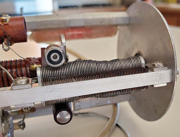
and to maintain their ability to be calibrated much longer. A visual
examination of the "M" versus the "CR" interior construction
will reveal no visible significant changes. A few minor
differences are apparent when examining the PTO
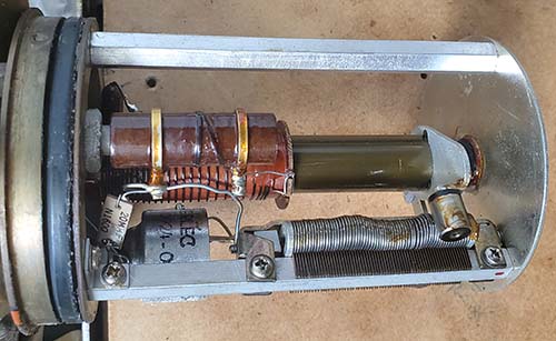
interiors "side-by-side." I've photographed the interiors of the
"M" and the "CR" PTOs and the comparison
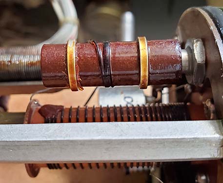
photos are further down in this section. I've also included
photos of the interior of a "no prefix-suffix" 51J-3 PTO that
had the "Collins one-turn removal" modification to L002
(performed at Collins in the 1950s.) The last contract for R-388 receivers was a small one in 1962
but the majority of R-388 receivers, those built from
1951 up to about 1955, are considered the "early" R-388 receivers and
those receivers
exclusively used the "M" version PTO. Why "M" versions develop
uncorrectable EPE - As it became apparent that something about
the 70E-15 "M" was causing an ever-increasing number of PTOs to
fairly rapidly develop "uncorrectable" end-point errors, meaning that the normal
L-trimmer adjustment had insufficient range to bring the PTO back
into specification, the first thought (by users and owners) was that the aging of an
unstable mix used in the ferrite
core was
causing the problem. It should be pointed out that all types of
Collins PTOs will change calibration over time and it was
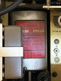
an expected aging factor. That's why the L-trimmer was provided. It's probably
also why the 70E-15 PTO's internal components were "sealed in a
vacuum" and why Collins insisted
that PTOs that had been field calibrated must be returned
to Collins for recalibration
where the vacuum seal was the last step in the process before
the corrected PTO was returned. However, the PTOs weren't
returned to Collins very often and therefore most PTOs had their
vacuum seal lost with the first adjustment for calibrating the
PTO and
thereafter the components inside, including the ferrite, were
exposed to the air and moisture which could then cause "rapid
deterioration" the PTO
components inside (the quote "rapid deterioration" is directly
from the Collins R-388 manual.) It's also possible that slight
seal leakage and a high moisture environment might have
contributed to the rapid development of excessive EPE.
|
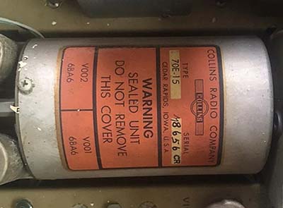
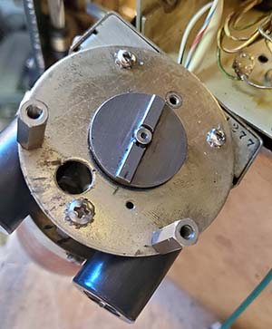
Identifying R-388 "M" PTOs |
|
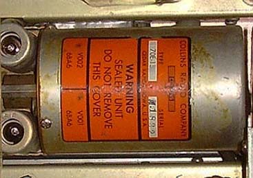
1951 R-388 PTO with "M" prefix serial
number |
1953 R-388 SN:4991 PTO with "M"
prefix SN |
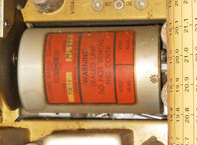
1953 contract R-388 (no data plate
- break in sw) Late SN PTO with "M" prefix |
Could the uncorrectable EPE have
been caused by the end user? - There weren't any
documented internal changes made to the 70E-15 PTO. The
PTO schematics shown in 51J-3, R-388 and 51J-4 manuals are all
identical. The only obvious external difference is that the
51J-4 regulated +150vdc was provided with better filtering with an added
electrolytic capacitor and a "T" filter on the 0A2 regulator
tube. This filtering change also shows up in the later R-388
receivers (1957 contracts.) Also, these later R-388 receivers
have PTOs that show both the "M" prefix and the "CR" suffix on
the same serial number, e.g., M11254C.R.
or M10816C.R. Since there aren't any differences in the 70E-15 PTOs that can
be shown on schematics and isn't too apparent in comparison
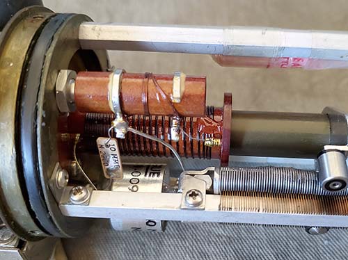
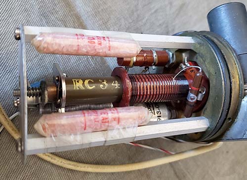
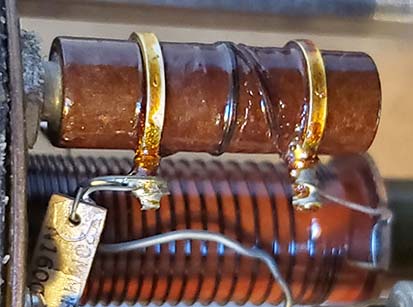
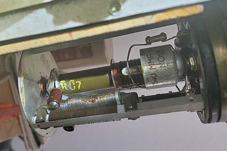
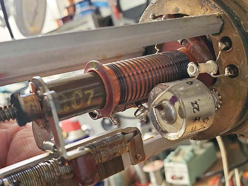
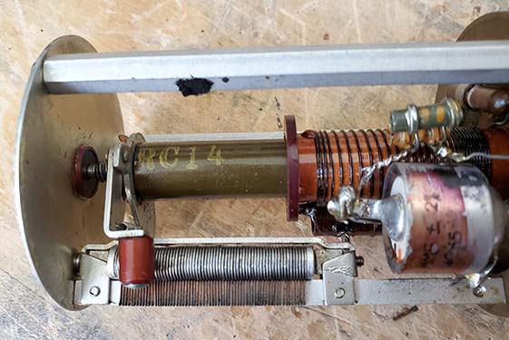
photographs, the difference must be something that's not visual, such as the type or mix of ferrite used in the
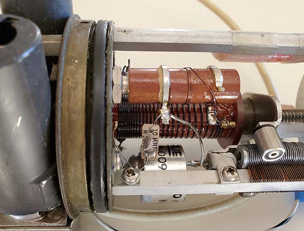
cores of "CR" PTOs. Note in the interior photos
further down this page that the ferrite cores are identified
implying some difference. So far, identifications of "no ID,"
"RC7," "RC14" and "RC34" have been encountered.
"CR" PTOs all use the "RC34" ferrite cores and that might be why
they hold their calibration much better than the "M" PTOs that
use other types of ferrite cores. But, for the "M" PTOs,
a contributing factor might be in how the receivers were used in the field.
Collins believed that the problem wasn't something that
happened to every 70E-15. It took a specific set of
circumstances in the field and then a few years for the
uncorrectable EPE to develop. While the ferrite core
might develop a correctable EPE just by aging,
the excessive and uncorrectable EPE problem probably started the first time that
the PTO was calibrated in the field with the removal of
the L002 L-trimmer access hex-plug that then allowed air and
moisture to enter the PTO. In their manuals, Collins even
mentions the possible contamination that could happen with a
field calibration "breaking the vacuum seal" and air-moisture
ingression causing "rapid deterioration" of the PTO's internal
components. In anticipation of possible vacuum-loss problems and
knowing that most customers were not going to return their PTO to
Collins for recalibration and resealing,
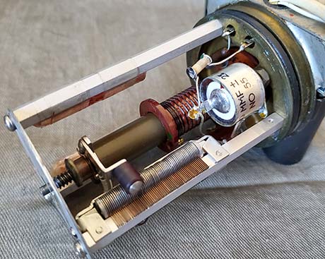
starting with the "CR" PTOs, Collins included two desiccant packets inside each 70E-15
"CR" PTO. Since the problem was
almost always with the
"M" PTO in R-388
receivers, it seems that the operational environment, where the
R-388 receivers were often turned on 24/7, could also have been
a factor, perhaps accelerating the
deterioration of PTO components after the vacuum loss.
Collins certainly wouldn't have
put too much time into analyzing a problem that they had plainly
addressed in the receiver manual for the "M" PTOs and had essentially
corrected with the "CR" version of the PTO in 1955.
Collins had been recalibrating 70E-15 PTOs that were returned
(usually inside a "returned for repair" commercial receiver, 51J-3 for
example) by removing one turn on the compensation inductor L002.
Later, when the "CR" PTO version was available,
Collins just replaced the older type PTO with a "CR" version (although there might have been an
extra cost for that repair option.) In fact, after 1954 and up to 1962, a total
of only about 1000 R-388 receivers were built on just a few military
contracts in those eight years. And, the 1957 and later R-388
receivers have more 51J-4 characteristics (including the "CR"
added to the serial number of these later PTOs) making these
late-R-388s significantly different than the early-fifties R-388s. Collins did
produce a write-up specifically on the early 70E-15 PTO around 1959 but exactly
what is covered in that document is currently unknown. I suspect
that Collins reiterated the "return to the factory for
calibration" but probably also revealed their "fix" for the the 70E-15 PTO
calibration adjustment that consisted of removing one turn from
the compensation inductor, L002 and then recalibrating the PTO.
It could have also suggested that the older PTO be replaced by
purchasing a new "CR" version replacement. I
can't find the Collins bulletin on the Internet or from the CCA. It's mentioned in a
Hollow State Newsletter but apparently Dallas Lankford couldn't
find a copy of it either. So, it's just speculation as to its
content.
More Experimenting and Speculation - About the only
popularly known research on the 70E-15
"M" problem has been by
a few collectors, starting with Bill Orr back in December 1969 with
Orr's write-up in 73 magazine. Orr's solution
of removing one turn on the L002 L-trimmer has been the commonly used "fix"
necessary to return the 70E-15 "M" to a somewhat useable accuracy.
However, as stated above, there's sufficient evidence that Collins was actually
performing this L002 modification to early PTOs that were
returned to the factory for repair and calibration in the
mid-fifties. Examination of the 70E-15 SN:755 from a 51J-3 that
was used commercially showed that L002 had only three turns but
was heavily recoated with lacquer. Interestingly, this PTO was
easily calibrated from an "as found" EPE of 12kc down to an EPE 3.2kc, which was the best that could be attained
today with the original ferrite core, ample air-moisture contamination
and only one turn removal on L002. Obviously, since the Collins
fix of the mid-50s and Orr's 1969 publication of the Collins
fix, 55 to 70 years have passed and that has allowed further PTO
component deterioration resulting in the fact that the "one-turn
removal" fix probably won't work all that well anymore.
Examples - What I've
noticed, although my examples are certainly limited, is that
nearly all R-388 receivers (14 receivers closely examined and
several "spares" PTOs examined) had
excessive EPE. Interestingly, out of five 51J-4 receivers examined,
three of which I had calibrated their PTOs, none
had uncorrectable EPE (the three cal'd PTOs were "C.R." versions of
the 70E-15 and were cal'd to <1kc EPE
using just L002.) Besides the "CR" PTO correction, perhaps
other factors might be considered, e.g., the 51J-4 being a
civilian receiver was much less likely to be operated 24/7 and
therefore the heat-build up never happened. Also, a 51J-4 being
civilian or commercial, probably never went through a scheduled
maintenance program that routinely calibrated the PTO. One very
important observation is the formidable disassembly
required just for PTO calibration certainly resulted in many 51J-4
receivers NEVER having their PTOs calibrated and that may have preserved their
internal vacuum environment much longer
than the typical R-388 "M" PTO. The result being
that the 70E-15 C.R. PTOs in 51J-4s are seldom found with excessive EPE that can't be
easily corrected with just a standard adjustment of the L-trimmer (I've
corrected several 51J-4 CR PTO's EPE just using L002. Also, one
1957 R-388 PTO that had both "M" and "CR" in the serial number.)
Additional specific examples follow,...
EXAMPLE A: I calibrated a 51J-3 70E-15 PTO SN:755 that had the
Collins "one turn removal on L002" fix done to it in the mid-1950s.
Initial EPE was 12kc. The best calibration I
could get with the modified 3-turn L002 was an EPE of 3.2kc end-to-end. The
implication is that the L002 "one-turn removal" may not work anymore as a
calibration fix although it will usually improve excessive EPE.
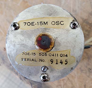
EXAMPLE B: On R-388 PTO M9145, the initial
measured EPE was 34kc. One turn was removed from L002 and that
lowered the EPE to 12kc but removing another half-turn didn't
change the EPE which remained at 12kc. The implication is that
as the ferrite cores age more and more (they're over 70 years
old now) the "one turn removal" fix doesn't work very well nowadays.
Of course, one has to remember the initial EPE was 34kc!
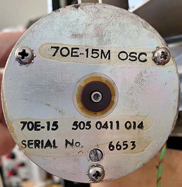
EXAMPLE C: I've recently calibrated a R-388 "M" PTO (SN:M6653) that had
NEVER
been calibrated before (by anyone.) The hex-plug still had its green Loctite
seal unbroken and the L002 trimmer shaft was at the top of its
adjustment range. This "M" PTO had an "as found" EPE of only
3.5kc. I was able to easily calibrate this "M" PTO to <1kc EPE and
<1kc linearity deviation with just one small adjustment of the L002
trimmer. This was an important discovery (well,...for me anyway)
in that it was a sort of empirical proof that it was the rapid loss of
vacuum due to removing the hex-plug for a field calibration
years ago that allowed rapid air-moisture ingression and that
caused the rapid deterioration of the PTO's internal components.
That didn't happen with PTO SN:M6653 and the slow leakage over
the years caused a slower change to the components and that has nowadays
allowed this PTO to be easily calibrated to specification. The
problem is finding a "M" version PTO that has never been
field calibrated. M6653 is the first one I've ever found.
Heat, Vacuum and N2
- This means that nearly ALL
early
R-388 receivers will have a 70E-15 "M" PTO with excessive EPE
and that probably was due to an early PTO field calibration that
caused a vacuum loss followed by moisture
ingression and then the deterioration was further accelerated by 24/7 operation
of the receiver. On the heat factor, a point could be made
that the R-390 and R-390A PTOs, the 70H-12, were designed to operate inside
an oven and these PTOs are never found (okay,...very
rarely found) with excessive EPE that
can't be adjusted out. Collins could and did produce the 70H-12
for a heated environment so why would the 70E-15 be adversely
affected by 24/7 heat build-up? The 70H-12 was "pressurized"
with nitrogen, an almost inert gas, which might have had
something to do with the longevity of the PTO calibration but,
like the 70E-15, the first EPE adjustment releases the N2
pressure and
air enters the PTO (I've only found one 70H-12 that still had
N2 pressure when I removed the plug to adjust the EPE - an
excellent seal that lasted for decades - but still, the EPE
needed a slight "touch-up" after those decades.) For the 70E-15, this again points to the
combination of the ferrite core being susceptible to contamination due to the
rapid loss of vacuum allowing rapid air-moisture ingression and 24/7
operation accelerating the aging and, even then, a problem that
really didn't develop immediately and only affected R-388
receivers built from late-1950 up to 1954.
|
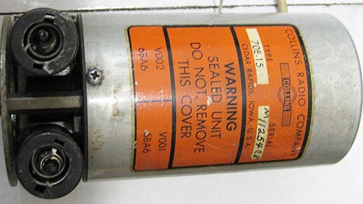
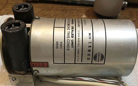
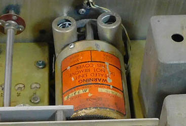
Identifying 51J-4 "CR" PTOs |
|

PTO in 1960 51J-4 SN:4723 showing the "C.R." suffix
|

PTO in 1959 51J-4 SN:3805 |
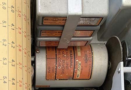
PTO in 1956 51J-4 SN:1616 Note
pre-printed "CR" not hand-written "C.R." |
Summary - The upshot is that ANY 70E-15 PTO
might be found with excessive EPE problems but almost all
of the "serious uncorrectable EPE problem" PTOs will be 70E-15 "M"
versions found in 1950 to 1954 (early) R-388 receivers. Sometimes a 51J-4 receiver equipped with the 70E-15 "C.R."
version PTO will be found with a "high" EPE but always the EPE can be corrected by calibrating the PTO just using the L002
trimmer provided. This uncorrectable EPE PTO problem will also
affect 51J-3 receivers since the PTOs use the same internal
components. The one 51J-3 PTO (SN:755)
examined
was found to already have the three-turn L002 correction
installed by Collins and this PTO calibrated fairly well,...not
to spec, but acceptable going from an "as found" 11.5kc EPE down
to a 3.2kc EPE (after all, the "fix"
might be approaching septuagenarian status.) Another 51J-3 had
its original PTO changed to a "CR" version and yet another 51J-3
had a very late replacement of a 70E-15 purchased spare with a SN of
>11,000. So, only 51J-3 PTO SN:755 can be used as a genuine
51J-3 reference. The good news is the
Collins three-turn L002 solution is a relatively easy "fix" for the uncorrectable EPE problem found in "M" PTOs in R-388 receivers. But, be aware
that it's not a perfect fix anymore. It will improve a
PTO with excessive EPE to "close to calibration" but there might
also be linearity problems and the adjustment range
will be significantly reduced in the attempt for a better EPE. The "BEST" fix
is to replace a "M" PTO with a "CR" PTO. Collins did that very
thing with 51J-3 SN:1999 which had a "CR" PTO installed at
Collins in 1957. This 51J-3 "CR" PTO recently was cal'd to <1kc
EPE and a linearity deviation of <1kc. THIS IS THE BEST FIX
for the "M" PTO with an uncorrectable EPE problem,
that is, replacement with a "CR" PTO. The good
news is that ALL 51J-4 receivers have their 70E-15 PTO
identified with a "CR" or "C.R." suffix added to the serial
number. ALL early R-388 receivers have their 70E-15 PTOs
identified with a "M" prefix to the serial number.
There are 70E-15 PTOs that don't have a prefix or a suffix on
the serial number. These PTOs are found in 51J-3 receivers
and also much later as replacement spares (serial numbers are
>11,000.) So, even if the PTO
has been removed from a receiver, it's still possible to tell in
which receiver the PTO was used. The letter suffixes and
prefixes were an identification that showed in which
type of receiver that particular 70E-15 was installed. "M" and "C.R."
End-Point Error Comparisons
- Now, I've found R-388 receivers with the "M" PTO that
haven't been worked on and didn't have an EPE that couldn't be adjusted to <1kc, but it's very rare
(2 out of 14 receivers examined.) Nearly all R-388 receivers
(that haven't had the PTO L002 modified) will have an end-point
error much greater than 10kc which for a "M" PTO might be beyond the
compensation adjustment. Nearly all "M" PTOs that I've tested have been
in the 8kc to 12kc area of EPE. The worst one I've ever tested was barely working and had an EPE
of 30kc! The best 70E-15 I ever tested was a NOS spare that was
found
still in the original box. This PTO was still in calibration and had no EPE!
NOTE: I recently (2025) had an opportunity to retest this
exact same NOS PTO several years later (about 15 years) and I found
that the EPE now is 2kc end-to-end indicating that the aging and
change is very slow. Also, I had the opportunity to retest and
attempt calibration of the original PTO that had the >30kc EPE,
that story is further down this page as "PTO M9145 - originally
from a 1953 R-388."
Confirmation That Loss of
Vacuum Caused "M" PTO Problems - The best
"in the receiver" 70E-15 "M" had an EPE of only 3.5kc (R-388
Collins Mfg SN 9108.) The NOS
PTO mentioned is an example that does
seem to indicate that vacuum loss due to removal of the hex plug
for calibration and the resulting air-moisture ingression could
be responsible for EPE problems since this NOS PTO had never
been calibrated and apparently still didn't require it. As a
confirmation for that hypothesis,...In 2026 I calibrated the "M"
PTO in R-388 SN:9108. As mentioned, this PTO had an "as found"
EPE of 3.5kc. When the PTO was dismounted from the receiver I
discovered that the hex-plug's green Loctite seal had NEVER been
broken. The PTO had NEVER gone through the calibration process
and therefore the vacuum environment was preserved as long as
the seals "held-out." Internally, as expected, the PTO was all
original with the four-turn L002 and with the slotted shaft of
L002 at the top of its adjustment. This PTO was easily
calibrated to <1kc EPE and <1kc linearity deviation with just
one 3/4 turn CW adjustment of L002. Totally atypical of the
normal "M" PTO and a sort of empirical proof that it was the
rapid loss of vacuum and the rapid air-moisture ingression the
caused the rapid deterioration of the PTO's internal components,
likely the ferrite core, that resulted in the uncorrectable EPE
problems.
Good News on "C.R." PTOs
- I just recently (Dec-2025) calibrated four 70E-15 "C.R." PTOs that had EPEs of 15kc,
11.5kc, 8.5kc and 4.5kc. All four of these "C.R." PTOs
were calibrated to <1kc EPE and about 1kc of linearity
deviation just
using L002. An interesting observation was on all but one of these PTOs,
the hex plug still had an "unbroken" green Loctite seal indicating these
three PTOs had NEVER been tampered with and the shield-cover
seal was still present although slightly cracked which is normal
for these fragile decal-type seals. However, the PTO that didn't
have the green Loctite seal on the hex-plug actually had the lowest
"as-found" EPE and
indications were the last calibration was in 1971 at Collins. That implies
that after 54 years, the EPE had only increased to 4.5kc.
However, since this particular PTO is in a Collins Laboratory
51J-4, it might have been possible that the 1971 Collins
calibration also resealed the vacuum environment in that PTO and
that's why it didn't change much in 54 years (again, just more
speculation.) Although an EPE test will show the current
condition of any PTO, actually trying to calibrate the PTO will
reveal how well preserved the internal parts are and, with some
adjustments of L002, it won't take too long to find out IF
the PTO can be calibrated.
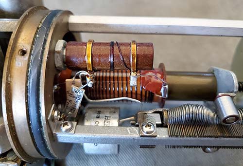
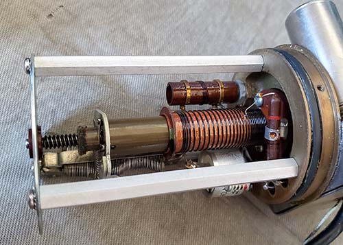
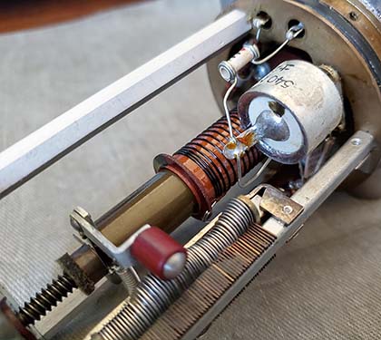
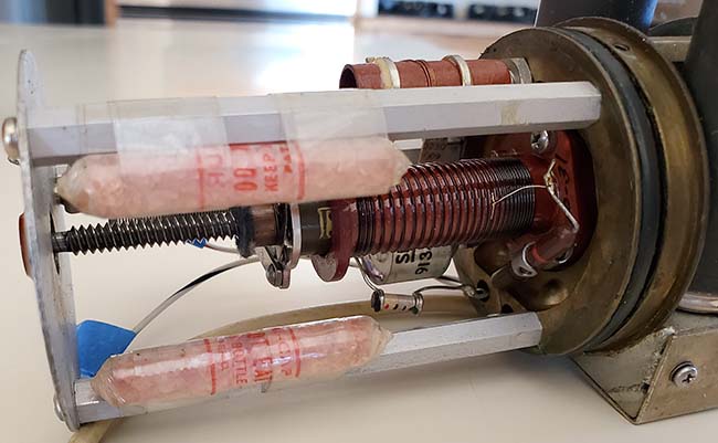
Photographic
Comparison Inside the 70E-15"M" and the 70E-15 "C.R."
and the 70E-15 "no prefix-suffix" 51J-3 PTO with the
Collins L002 fix and more
- Nowadays, in 2025, with nearly 70 years of aging, even
51J-4 "CR" PTOs are commonly found with a fairly high EPE which seems
to indicate that after decades of existence, the PTO seals have
broken down and allowed a slow ingression of air-moisture into the PTO
body (the desiccant packs have certainly "turned pink.") It's rare to find a "CR" PTO that has had its hex-plug
removed, so the failure of the vacuum seals seems to be a
logical assumption to add to the list of other "factors" for the
PTO EPE issues. It's not unusual for R-388 "M" PTOs to be found with >12kc
of EPE today and 51J-4 "C.R." PTOs generally are found with
4kc to 8kc
of EPE. However, if air-moisture contamination (loss of vacuum) is
the root cause, then Collins was correct in their statement that
accessing L002 to calibrate the PTO was only a temporary
field fix and the
PTO needed to be sent back to Collins as soon as possible for
proper calibration and sealing (restoring the vacuum.)
>>>
|