|
AA - 365kc - Fargo, ND - 100W
ADT - 365kc - Atwood, KS
AE - 351kc -
Dudle-Albuquerque, NM
AEC - 209kc - Base Camp, NV -
OTA
AFK - 347kc - Nebraska
City, NE - 25W
AGZ - 392kc - Wagner, SD
AL - 353kc - Trina (Walla
Walla,) WA
AM - 251kc - Amarillo, TX - 400W
AN - 368kc - San Antonio,
TX
ANR - 245kc - Andrews, TX
AOP - 290kc -Rock Springs, WY - 100W
AP - 260kc - Denver, CO - 100W
AP - 378kc - Active Pass, BC, CAN
ATS - 414kc - Artesia, NM - 25W
AUB - 355kc -"Saldo"King
Salmon, AK <10-3-20PL
AVQ - 245kc - Tucson, AZ
AW -382kc -"Waton"
Arlington, WA <2-7-20 PL
AZC - 403kc - Colorado City, AZ
BAJ - 392kc - Sterling, CO
BBD - 380kc - Brady, TX - 25W
BF - 362kc - Nolla-Seattle,WA
BI - 230kc -
Jadan-Bismarck, ND
BK - 335kc -
CHRLZ-Brookings, SD 25W
BKU - 344kc - Baker, MT - 80W
BM - 375kc - Balmoral, MB,
CAN 25W<12-30-19 PL
BO - 359kc - Boise, ID - 400W -
OTA
BR - 233kc - Brandon, MB, CAN
BWR - 412kc - Alpine, TX -
25W
BY - 211kc - Beechy, SK,
CAN
CBC - 415kc - Cayman Brac, Cayman Islands
CC - 335kc - Buchanan AF, CA - 25W
CD - 362kc - "Dawes" Chadron, NE
<1-9-20 PL
CEP- 278kc - Ruidoso, NM - 25W
CG - 227kc - Castlegar, BC, CAN
CH - 329kc -
Ashly-Charleston, SC - 400W
CHD - 407kc - Chandler, AZ
CII - 269kc - Choteau, MT - 50W
CIN - 397kc - Carroll, IA - 25W
CKP - 423kc - Cherokee, IA - 25W
CL - 515kc - Port Angeles, WA
CLB - 216kc - Wilmington, NC - 1KW
CN - 235kc - Cochrane, ON,
CAN 100W
CNP - 383kc - Chappell, NE - 25W
CO - 407kc
- "Petey" Colo.Sprgs, CO 25W >11-7-20 PL
COR - 205kc - Corcoran, CA
- 25W
CRK - 389kc - Spokane, WA
CRR - 245kc - Circle, MT - 100W
CRZ - 278kc - Corning, IA - 25W
CSB - 389kc - Cambridge, NE - 25W
CUH - 242kc - Cushing, OK - 25W
CVP - 335kc - Helena, MT - 150W
CY - 353kc - Cheyenne, WY
CYW - 362kc - Clay Center, KS - 25W
CZX - 332kc - Crosbyton,
TX
DAO - 410kc - Ft. Huachuca, AZ
DB - 341kc - Burwash Landing,YK,CAN
DC - 326kc - Princeton, BC, CAN
DDP - 391kc - San Juan, PR - 2KW
DIW - 198kc - Dixon, NC - 2KW
DL - 379kc - "Pykla"
Duluth, MN <12-20-19 PL
DN - 225kc - Dauphin, MB, CAN
DPG - 284kc - Dugway Prov Gnds, UT
DPY - 365kc - Deer Park,
WA - 25W
DQ - 394kc - Dawson Creek, BC, CAN
DUT - 283kc - Dutch Harbor, Amakrak Is., AK
DWL - 353kc - Gothenburg, NE - 25W
EC - 217kc - Cedar City, UT - 25W
EEF - 391kc -"Elephant"Sisters
Is., AK < 9-27-19
EF - 206kc - Champion-Castlegar, BC, CAN
EHA - 377kc - Elkhart, KS
- 25W
EHM - 385k -Cape
Newenham,AK 100W
EKS - 286kc - Ennis, MT - 25W
EL - 242kc - El Paso, TX - 400W
ELF - 341kc - Cold Bay, AK - 1KW
ENS - 400kc - Ensenada, Mexico
ENZ - 394kc - Nogales, AZ - 100W
EOK - 366kc - Keokuk, IA -
25W <2-14-20 PL
ESY - 338kc -
West Yellowstone, MT - 100W
EUR - 392kc - Eureka, MT - 100W
EX - 374kc - Kelowna, BC, CAN
FBY - 293kc - Fairbury, NE
50W <1-29-20 PL
FCH - 344kc - Fresno, CA - 400W -
OTA
FF - 337kc-"Hamre"Fergus
Falls, MN 12-23-22PL
FH - 304kc -
Whitecourt, AB,
CAN 25W<2-20-20 PL
FIS - 332kc - Key West, FL - 400W
FMZ - 392kc - Fairmont, NE - 25W
FN - 400kc - Ft. Collins, CO
FO - 250kc - Flin Flon, MB, CAN
FOR - 236kc - Forsyth, MT - 25W
FQ - 420kc - Fremont, MN - 25W
FS - 245kc - Sioux Falls, SD - 100W
FS - 375kc - Ft. Simpson, NWT, CAN
GB - 253kc - 'Garno' -
Marshall, MN
GB - 419kc -
"Babsy"Great Bend, KS 25W >11-7-20 PL
GC - 380kc - Gillette, WY
GDV - 410kc - Glendive, MT - 100W
GEY - 275kc - Greybull, WY
GGF - 359kc - Grant, NE
GHW - 346kc - Glenwood, MN
25W<1-9-20 PL
GLS - 206kc - Galveston,TX-2KW -
OTA
GLY - 388kc - Golden
Valley-Clinton, MO
GNC - 344kc - Seminole, TX - 25W
GRN - 382kc - Guerrero Negro, Mexico
|
GRN - 414kc - Gordon, NE
GUY - 275kc - Guymon, OK - 25W
GW - 371kc - Jarpik, Kuujjuarapik, QC, CAN
GYZ - 280kc - Guernsey, WY - 50W
HAU - 386kc - Helena, MT
HBT - 390kc - Sand Point,
AK
HCY - 257kc - Cowley, WY
HDG - 211kc - Gooding, ID - 50W
HE - 245kc - Hope, BC, CAN
HF - 241kc - Hearst, ON,
CAN 100W
HIN - 275kc - Chadron, NE - 25W
HJH - 323kc - Hebron, NE - 25W
HLE - 220kc - Hailey, ID - 50W
HQG - 365kc - Hugoton, KS - 25W
HRU - 407kc - Herington,
KS - 25W
HRX - 341kc - Hereford, TX
HY - 374kc - "Nette" Hays,
KS <12-20-19 PL
IB - 209kc - Atikokan, ON, CAN
ICL - 353kc - Clarinda, IA
- 25W
ID - 324kc - Idaho Falls,
ID
IKY - 429kc - Springfield, KY - 25W
ILT - 247kc - Albuquerque,NM - 400W
IN - 353kc - International
Falls, MN - OTA
INE - 521kc - Missoula, MT - 400W
IOM - 363kc - McCall, ID - 25W
IP - 201kc - Mobile, AZ
ITU - 371kc - Great Falls, MT - 100W
IY - 417kc - Charles City, IA - 25W
JDM - 408kc - Colby, KS -
25W
JHN - 341kc - Johnson, KS
JM - 396kc - Jamestown, ND
JNR - 382kc -"North
River"Unalakleet, AK < 9-27-19
JW - 388kc - Pigeon Lake, AB, CAN
K2 - 376kc - Olds-Didsbury, AB, CAN
L4 - 402kc - Nipawin, SK,
CAN - 200W <11-13-19 W
LAC - 328kc - Ft. Lewis, WA - 25W
LBH - 332kc - Portland, OR - 150W
LD - 272kc - Lubbock, TX
LF - 336 - LaSalle, MB,
CAN 50W
LFA - 347kc - Klamath Falls, OR
LGD - 296kc - LaGrande, OR - 25W
LLD - 353kc - Lanai City, HI - 2KW
LLN - 266kc - Levelland, TX
LU - 213kc - Abbotsford, BC, CAN
LV - 374kc - Livermore,CA - 25W
LW - 257kc - Kelowna, BC, CAN
LWG - 225kc - Corvallis,
OR
LWT - 353kc - Lewiston, MT - 400W
LYI - 414kc - Libby, MT - 25W
LYQ - 529kc - Manchester, TN
L7 - 395kc - Estevan, SK,
CAN
MA - 326kc - Midland,TX - 400W
MA - 365kc - Mayo, YK, CAN
MB - 293kc - Mill Bay, Victoria, BC, CAN
25W<2-1-20 PL
MDS - 400kc - Madison, IA - 25W
MEF - 356kc - Medford, OR
MF - 373kc - Rogue Valley, OR
MKR - 339kc - Glascow, MT - 50W
ML - 392kc - Charlevoix, QC, CAN
MLK - 272kc - Malta, MT - 25W
MM - 388kc - Fort McMurray,AB,CAN
MNC - 348kc - Shelton, WA
MNZ - 251kc - Hamilton, TX - 25W
MO - 224kc - Moosonee, ON,
CAN <1-29-20 PL
MO - 367kc - Modesto, CA -
OTA
MOG - 404kc - Montegue, CA - 100W
MR - 385kc - Monterey, CA
MW - 408kc - Moses Lake, WA
NA - 337kc - Orange County AP, CA
NM - 278kc - Matagami, QC, CAN
NO - 351kc - Reno, NV - 25W -
OTA
NY - 350kc - Enderby, BC, CAN -
OTA
OCC-385kc-"OceanCape"Yakutat,AK,TWEB<2-14-20PL
ODX - 355kc - Ord, NE - 25W
OEG - 413kc - Yuma Proving Grounds, AZ
OEL - 381kc - Oakley, KS - 25W
OIN - 341kc - Oberlin, KS - 25W
OJ - 239kc - High Level, AB, CAN
OKS - 233kc - Oshkosh, NE
- 25W
OLF - 404kc - Wolf Point.
MT - 100W
ON - 350kc - Newport, OR
ON - 356kc - Penticton, BC, CAN
ONO - 305kc - Ontario, OR
ORC - 521kc - Orange City, IA - 25W
OT - 378kc - Bend, OR
OUN - 260kc - Norman, OK - 25W
OWU - 329kc - Woodward, OK
PA - 396kc - Snohomish/Ritts, WA
PA - 347kc - Prince Albert, SK, CAN
PBT - 338kc - Red Bluff, CA -400W
OTA
PBY - 259kc - Kayenta, AZ
PD - 230kc - Pendelton, OR - 400W
PDG - 327kc - Watsonville, CA - 25W
PFT - 342kc - "Piney"
Pinecreek, MN <1-31-20 PL
PG - 353kc - Portage, MB, CAN
PI - 383kc - Tyhee, ID
PJ-329kc-Robinson-Whitehorse,YT,CAN250W<10-21-20
PKZ - 326kc
-"Pickens"Pensacola,FL400W<1-1-20PL
PMV - 329kc-Plattsmouth,NE 25W <11-23-2019
PL
|
PN - 360kc - Port Menier,
Anacosti Is., QC, CAN
PNA - 392kc - Pinedale, WY - 25W
PND - 356kc - Portland, OR
POA - 332kc - Pohoa-Hilo,
HI
POH - 428kc - Pocahontas, IA - 25W
POY - 344kc - Powell, WY
PPA - 450kc-Puerto Plata,
Dominican Republic
PR - 218kc - Prince
Rupert, BC, CAN < 9-30-19
PRZ - 407kc - Portales, NM - 25W
PTT - 356kc - Pratt, KS - 25W
PY - 207kc - Ft.
Chipewyan, AB, CAN
PYX - 266kc - Perryton, TX - 25W
QD - 284kc - The Pas, MB, CAN
QL - 248kc - Lethbridge,
AB, CAN
QN - 233kc - Nakina, ON,
CAN
QQ - 400kc - Comox, Van.Is., BC -
OTA
QR - 290kc - Rigina Int'l,
SK, CAN
QT - 332kc - Thunder Bay, ON, CAN
QU - 221kc - Grand
Prairie, AB, CAN
QV - 385kc - Yorkton, SK, CAN
QW - 302kc - North
Battleford, SK, CAN
RA - 254kc - Rapid City, SD - 100W
RD - 367kc - Redding Muni, CA - 25W
RD - 411kc - Redmond, OR - 400W
RG - 274kc - Red Wing, MN
25W <1-29-20 PL
RG - 350kc-Will Rogers World AP,
OKC,OK
RJ - 378kc-Roberval,QC,CAN
500W<12-30-19 PL
RL - 218kc - Red Lake, ON, CAN
RMD - 204kc - McDermitt, OR - 25W
RNT - 353kc - Renton, WA - 25W
RO - 305kc - Roswell, NM -
400W <1-1-20 PL
RPB - 414kc - Belleville, KS
RPX - 362kc - Roundup, MT - 25W
RWE - 528kc - Camp Roberts, CA
RWO - 394kc - Kodiak, AK -
TWEB Voice WX
RYN - 338kc - Tuscon, AZ - 400W
SA - 356kc - Sacramento,CA
SAA - 266kc - Saratoga, WY - 25W
SAK - 515kc - Kalispell, MT - 25W
SB - 397kc - San Bernadino,CA
SB - 362kc - Sudbury, ON, CAN
SBX - 347kc - Shelby, MT - 25W
(sends SDX or UDX)
SC - 271kc - Stockton,CA
SCO - 283kc - Scobey, MT
SDA - 411kc - Shenandoah,
IA - 25W
SDY - 359kc - Sidney, MT - 25W
SF - 379kc-San Francisco Intn'l AP, CA
SG - 341kc - Santa Fe, NM
SIR - 368kc - Sinclair, WY
SIT - 358kc - Sitka, AK >
10-8-20 PL
SKX - 414kc - Taos, NM - 25W
SL - 266kc - Salem, OR -
OTA (now SLE)
SLB - 434kc - Storm Lake, IA - 25W
SLE - 266kc - McDerrmit
AP, Salem, OR
SM - 230kc - Metre/Sacramento, CA
SM - 254kc - Fort Smith,
NWT, CAN
SOW - 206kc - Show Low, AZ - 25W
SRL - 270kc - Santa Rosalia, MEX
STI - 333kc - Mt. Home, ID
SU - 414kc -
"Salix" Sioux City, IA 40W >11-7-20>PL
SWT - 269kc - Seward, NE - 25W
SWU - 350kc - Idaho Falls, ID
SX - 367kc - Cranbrook, BC, CAN
SYF - 386kc - St. Francis, KS - 25W
SYW - 428kc - Greenville, TX - 25W
SZT - 264kc - Sandpoint,
ID
TAD - 329kc - Trinidad, CO
TCY - 203kc - Tracy, CA
TF - 373kc - Pueblo, CO
TH - 244kc - Thompson, AB, CAN
TK - 392kc -
Telkwa/Smithers, BC, CAN
TOR - 293kc - Torrington,
WY
TQK - 256kc - Scott City, KS - 25W
TV - 299kc - Turner Valley, AB,CAN
TVY - 371kc - Tooele, UT - 25W
TW - 389kc - Twin Falls,
ID
U6 - 360kc - Creston, BC, CAN
UAB - 200kc - Anahim Lake, BC,CAN
UK - 371kc - Kearn, CA
ULS - 395kc - Ulysses, KS - 25W
UNT - 312kc - Penticton,
BC, CAN
UVA - 281kc - Uvalde, TX - 25W
VC - 317kc - LaRonge, SK, CAN
VG - 230kc - Vermillion,
MB, CAN
VQ - 400kc - Alamosa, CO
VR - 266kc - Vancouver, BC, CAN
VT - 332kc - Buffalo Narrows, SK, CAN
VTR -350kc-Takotna
River, McGrath, AK<2-1-20 PL
VV - 326kc - Wiarton, ON,
CAN 400W<1-9-20 PL
WC - 332kc - White Rock
BC,CAN<2-18-20 PL
WG - 248kc - Winnepeg, MA,CAN
WL - 385kc - Williams Lake, BC, CAN
XC - 242kc - Cranbrook, BC , CAN
XD - 266kc - Edmonton, AB, CAN
XE - 257kc - Saskatoon, SK, CAN
XH - 332kc - Medicine Hat, AB, CAN
XJ - 326kc - Fort Saint John, BC, CAN
XS - 272kc - Prince George, BC, CAN
XT - 332kc - Terrace, BC, CAN
XX - 344kc - Abbotsford, BC, CAN
|
X2 - 328kc - Athabacsa,
AB, CAN < 9-30-19
YAG - 376kc - Fort
Frances, ON, CAN
YAT - 260kc - Attawapiskat, ON, CAN
YAZ - 359kc - Tofino,Van.Is., BC, CAN
YBE - 379kc - Uranium City, SK, CAN
YBL - 203kc - Campbell
River, BC, CAN
YBV - 370kc - Berens River
AP, MB, CAN
YC - 244kc - Cranbrook, BC, CAN
YCD-251kc - Nanaimo, Van. Is, BC, CAN
YCO - 375kc - Kugluktuk,
NU, CAN
YD - 230kc - Smithers, BC, CAN
YE - 382kc - Fort Nelson, BC, CAN
YEK - 329kc - Arviat, NU,
CAN 500W <12-13-19 PL
YEL - 276kc - Elliot Lake, ON, CAN
YER - 334kc-Fort
Severn, ON, CAN 195W <12-8-19 PL
YFM - 332kc-LaGrande
4,QC,CAN 2KW <12-5-19 PL
YHD - 413kc - Dryden, ON, CAN
YHN - 329kc - Hornepagne, ON, CAN
YIV - 300kc - Island Lake,
MB, CAN
YJ - 200kc - Victoria
Island, BC, CAN
YJQ - 325kc - Bella Bella, BC, CAN
YK - 371kc - Yakima, WA
YK - 269kc - Castlegar, BC, CAN
YKA - 223kc - Kamloops, BC, CAN
YKQ - 351kc - Waskaganish, QC, CAN
YL - 395kc - Lynn Lake, MB, CAN
YLB - 272kc - Lac la Biche, AB, CAN
YLD - 335kc - Chapleau, ON, CAN
YLJ - 405kc - Meadow Lake, SK, CAN
YLL - 241kc -
Lloydminster, AB, CAN
YLQ - 289kc - La
Tuque,QC,CAN 500W<2-26-20 PL
YMW - 366kc - Maniwaki, QC, CAN
YNC - 385kc - Wemindji,
QC, CAN 25W <1-27-20 PL
YNE - 207kc-Norway
House,MB,CAN 1KW<12-10-19 PL
YPH - 396kc - Inukjuak, QC, CAN
YPL - 382kc - Pickle Lake, ON, CAN
YPM - 274kc - Pikangikum, ON, CAN
YPO - 401kc - Peawanuck, ON, CAN
YPW - 382kc - Powell River, BC, CAN
YQ - 305kc -
Churchill/Eastern Creek, MB, CAN - 500W
YQA - 272kc - Muskoka, ON, CAN
YQF - 320kc - Red Deer, AB, CAN
YQK - 326kc - Kenora, ON, CAN
YQZ - 359kc - Quesnel, BC,CAN
YSQ - 260kc - Atlin, BC, CAN
YTL - 328kc - Big Trout Lake, ON, CAN
YWB - 389kc - West Bank, BC, CAN
YWP - 355kc - Webequie, ON, CAN
YXL - 346kc - Sioux Lookout, ON, CAN
YXR - 257kc - Earlton, ON,
CAN 400W
YY - 340kc - Mont Joli, QC, CAN
YYF - 290kc - Penticton, BC, CAN
YYU - 341kc - Kapuskasing, ON, CAN
YYW - 223kc - Armstrong, ON, CAN
YZA - 236kc - Ashcroft, BC,CAN
YZE - 245kc - Gore Bay, ON, CAN
YZH - 343kc - Slave Lake, AB, CAN
ZAB - 214kc -
Leduc/Edmonton IAP, AB, CAN
ZEG - 379kc - Edmonton,
AB, CAN
ZF - 356kc - Yellowknife, NWT, CAN
ZHD - 399kc - "Thunder" Dryden, ON, CAN
ZKI - 203kc - Kitimet, BC,
CAN
ZQ - 410kc - Sir Wilfred
Laurier CCGS*, BC, CAN
ZP - 368kc - Sandspit, Queen
Charlott Is, BC, CAN - OTA
ZPA - 372kc -
Prince Albert, SK, CAN 25W <12-20-19 PL
ZRG - 414kc - Regina, SK,
CAN
ZSJ - 258kc - Sandy Lake, ON, CAN
ZSS - 397kc - Yellowhead-Saskatoon, SK, CAN
ZT - 242kc - Port Hardy, BC, CAN
ZU - 338kc - Whitecourt, BC, CAN
ZVR- 369kc - Vancouver
(Sea Is.,) BC, CAN
ZXE - 356kc - Saskatoon,
SK, CAN
ZYC - 254kc - Calgary, AB,
CAN
ZZD - 308kc
- Calmar/Edmonton Int'l AP, AB, CAN
ZZP
- 248kc
- Sandspit, Queen Charlotte Is, BC, CAN -
OTA
Z1 - 305kc - Three Hills,
AB, CAN 25W <12-8-19 PL
Z5 - 274kc - Vulcan, AB, CAN
Z7 - 408kc - Claresholm, AB, CAN
3Z - 388kc - Taber, AB, CAN
4W - 391kc - Kelsey, MB,
CAN 25W<1-23-20 PL
5J - 328kc - Coronation,
AB, CAN 141W<1-9-20 PL
6T - 362kc - Foremost, AB, CAN
9Y - 311kc - Pincher
Creek, AB, CAN - 50W
Weird Beacons Copied Multiple
Times**
INUU - 395kc - 11/2017 (also in 2016, 2019)
EEGU - 378kc - "Key Down-CAN?" - 11/2017,
12/2019
TTOO - 379kc - Key down CAN? - 11/6/2021
EAELA - 358kc - 11/12/2024
OTA - Off The
Air, Decommissioned
* Canadian Coast Guard Ship - NDB for heliport
onboard
** not counted in total received
NOTE 2022: It's
probably worth mentioning that I started this log in 2006 or about 18 years ago. In
looking over the list of NDBs, I thought that at least 50% of these
stations have been decommissioned over those years. In actuality, it's
probably closer to 65% that have been decommissioned and that percentage
keeps increasing each year. NDBs are being decommissioned faster than I
can find newly heard NDB stations. |
|


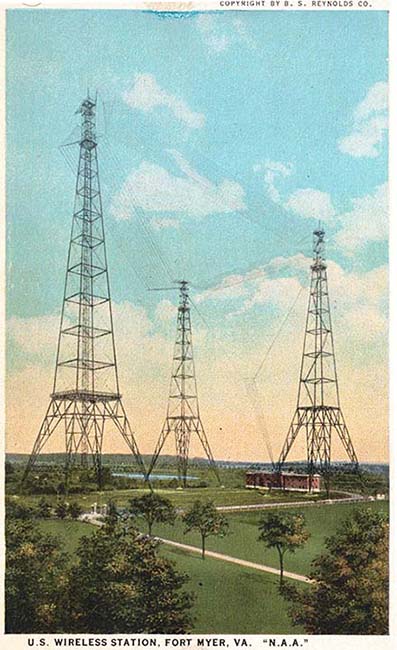
 NAA
NAA NLK
NLK