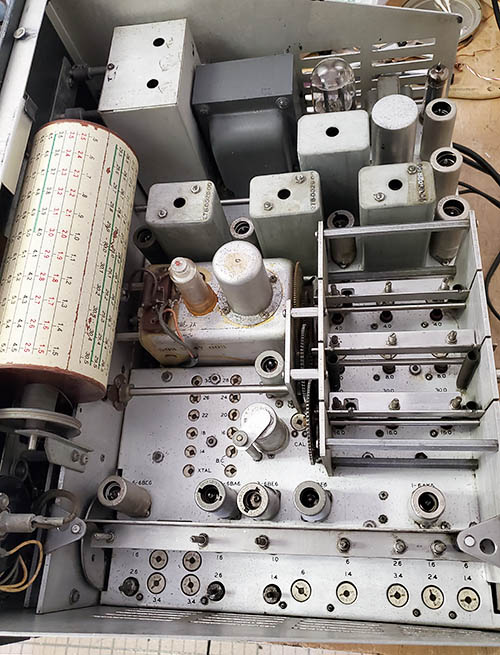
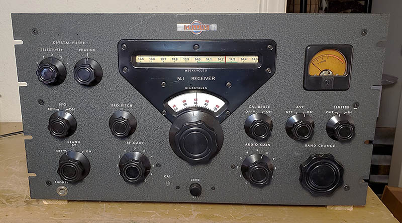
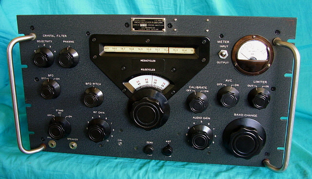
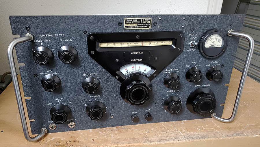
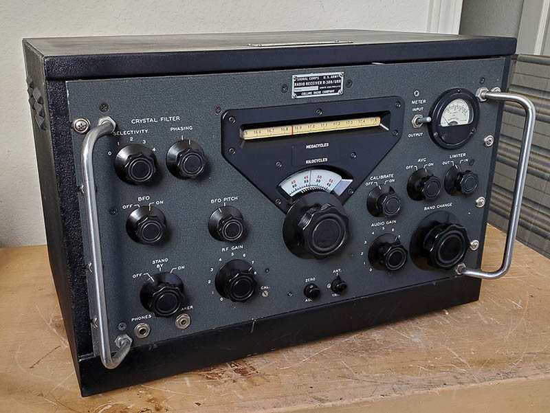
Radio Boulevard
Western Historic Radio Museum

COLLINS RADIO COMPANY

51J Series of Receivers

PART 3

Rebuilding a 1949 51J-1 SN:652, Rebuilding a 51J-2 Receiver Requires a "Parts Set"
Rebuilding a R-388/URR "Basket Case" that Morph'd to a 1952 Collins SN:1743, Mil SN:95
Refurbishing a 1952 R-388/URR Collins SN:9108, Mil SN:161 with Military CY-1260/G Cabinet
 

On to Part 4          Back to Part 1               Back to Part 2


51J-3 Manual Cover Artwork


PART 3


Rebuilding the Collins 51J Series Receivers
 

1949 51J-1 Restoration

When I purchased this 51J-1 it had already been "gone through" electronically in the form of replacing the electrolytics and a few paper dielectric capacitors. It did seem to function pretty well although there were several minor issues. So, this is going to be mainly a cosmetic restoration - hopefully. These types of restorations are always going to have "surprises" that are found as the receiver is disassembled and even more "surprises" will be found as the receiver goes through the entire electronic process necessary for it to become a fully and correctly operating receiver. Though this 51J-1 is the most original and complete one I've ever seen, it still has some minor modification issues that are both electronic and cosmetic. The length of this write-up will be determined by the number of "surprises" that I always seem to find as any restoration progresses.


1949 Collins 51J-1
 "As delivered." The front panel seems like a "flat finish" but it's just devoid of any luster. The knobs, likewise, are flat and have no color depth. The S-meter has darken considerably from sun exposure. The sunburned KC dial isn't showing in this photo but it is shown in the next photo down to the right.

Preliminary Inspection - Cosmetic Issues

1. Sunburned section of the KC dial - It's severely discolored (not shown in photo to the left.) The discoloration is of the middle section of the three-part laminate making up the dial, so it must have been exposed to bright sunlight for decades. I have a spare 51J-2 KC dial but can't find it at the moment (an extensive search has proven futile.) Repro KC dial from W3HM, installation on original hub write-up at the end of this article.
2. Small dent in the dial escutcheon (by "51J.") This is a minor dent that's only noticeable in certain light or viewing angles. Should respond to bodywork techniques (it did.)
3. The "hold down" assembly for the 100kc crystal is missing. I have a spare assembly from the 51J-2 parts set.
4. Missing trim screws below the tuning knob. These screws are in all 51J receivers and were intended for something that apparently was never installed. The screws just "fill" the tapped holes. I have original spare screws.
5. Darkened S-meter scale. This is the same scale that's used on the 75A-1 receiver. It's not bad but I'll keep an eye out for a spare 75A-1 S-meter to show up some day (or maybe I can recondition this one,...a surprise,...that worked!)
6. ZERO adjust knob is a more modern type. I have several spare original types.
7. Tuning knob and Band Change Knob both need attention. The skirt on the tuning knob is "flat black" - might be paint. Band Change knob needs to have a crank fitted. I might have a spare crank.
8. Dial fiduciary (index line) seems to bend and flex with tuning and especially when adjusting the ZERO ADJ. I have to pull the front panel to see what's going on. I have a spare 51J-2 fiduciary, if needed (the problem was that the dial glass had slipped out of its retaining clips and was allowing the index to rub against it.)
9. Although very minor, the power transformer was painted black at sometime in the past. It wasn't removed from the chassis but was painted in place with a brush. The original color was gray. I'll repaint the same way (turned out looking great.)
10. General clean-up required. Front panel is rather "flat" looking. Just needs some reconditioning. Chassis has a lot, a whole lot, of gritty dirty deposits all over. It brushes off pretty easily. Also some minor pitting that might respond to cleaning.

Preliminary Inspection - Functionality

1. The receiver actually works pretty well but there are several minor problems. They don't really affect the actual reception of signals but are in other areas of performance. Bandwidth seems a lot wider than expected.
2. BFO set up incorrectly. Couldn't select sidebands properly. Easy 5 minute fix.
3. The 70E-7A PTO had an EPE that tested at an incredible 12kc off! I did have to calibrate the 100kc oscillator and then I did verify the results using the HP 606B and DFC. I've never run into a 70E-7A that had this much EPE but maybe it has never been adjusted at all,...ever! If the 12kc EPE doesn't adjust out, I do have a spare 70E-7A PTO that I could use as a replacement (all of the 70E-7A PTOs that I've tested before had an EPE of 1kc or 2kc. The actual cause of this unusually high EPE wasn't the PTO. It's covered in "Another PTO Surprise" further down in this write-up.)
4. This is partially cosmetic but I will be replacing the modern molded AC plug type of power cable with a more vintage-correct power cable. The original AC power cable was a two-conductor, black rubber "zip cord" with a period molded type AC plug installed. Original length was six feet long.  
5. I might do something about the re-cap job that, although excellent work, used the intensely-yellow polyfilm caps. Nice caps but terrible in appearance. I usually paint them dark gray and use color code "dots" for a more vintage appearance. Also, the replacement electrolytic caps might be placed inside the original cans since those are still present.
6. And, speaking of capacitors, someone added 3pf capacitors across the IF transformers. These are "coupling" capacitors that are found in later R-388 receivers and in all 51J-4 receivers. It's possible that someone just copied the J-4 schematic not knowing why the caps are there in the J-4 or it could also be that someone was looking for a broader IF bandwidth. The J-2 (and certainly the J-1) had a very narrow IF passband (4kc to 5kc at -6db) and do have a tendency to sound "muffled." I'll have to consider this "originality versus modification for modern usage" but I think I'll probably go with original and remove the caps.

Both cosmetic and functionality inspections were performed on May 1, 2023

51J-1 showing the "sunburned" KC dial

Disassembly - Thorough cleaning required because this receiver has been somewhere that had a lot of coarse grit that was airborne and was deposited all over the chassis top. Also, several brackets and some screws seem to have a powdery type of corrosion that brushes off easily. This receiver came from New Jersey, so an East Coast "coastal environment" is probable. Mostly just a gritty type of coarse black deposit,...luckily it seems to brush off pretty easily.

Front Panel Dismount - To clean, touch-up and recondition the front panel required dismounting all of the knobs, controls, S-meter, dial bezel and screws. This then allowed complete access to the entire front surface of the panel. Actually, the panel was relatively clean but it didn't have any luster that the St. James Gray wrinkle paint should have. Another thing is the tint of late-forties St. James Gray is a shade or two lighter than the St. James Gray found on the 75A-4 (as an example of the later, darker St. James Gray.) Touch-up has to be custom matched. It does have some earlier touch-up that probably was pre-mixed St. James Gray since it doesn't match very well. Of course, it's possible that most of the early St. James Gray examples I've seen were just somewhat faded with time and exposure to light. Where necessary, I did a touch-up with my "custom matched" paint (this paint has to be matched after the panel reconditioning since the final color is what the "match" is to.) The final part of reconditioning is to give the panel a rubdown using "3 in 1" oil (or any light-weight machine oil.) This is applied with a clean cotton cloth in a circular pattern and allowed to set for a few minutes. Then the oil is wiped off with another clean dry cloth. This is repeated the next day. This treatment restores the wrinkle finish luster in a subtle manner. Not glossy like Armor-All (which is also very slippery) or possessing that persistent, ever-lingering odor of Boiled Linseed Oil.

Nothing unusual was found in the front panel dismounting. All locking washers were present but, in this case, all of the locking washers were on the inside of the panel (not mixed like the R-388s are.) The S-meter has a small tie-point mounted on the upper right stud that should be noted when dismounting the meter. Also, the S-meter was mounted with locking washers but many other screws and nuts didn't have locking washers. Some of the screws appeared to have "green Loctite" applied to take the place of locking washers. Other nuts just appear to have been removed and then replaced with the locking washer left out.

Dial Escutcheon Bodywork - It's fairly difficult to remove a small dent when the surface is painted and has some sheen. The first step is to not be too aggressive. It takes time working in small steps to remove the dent without damaging either the paint or making the bodywork look worse than the dent did. I protected the paint with a heavy paper (a piece of manila folder.) I made sure I was going to work on a flat surface. I used a single layer of blue masking tape to pad the area on the backside of the dent. I used a small wooden block as an interface between the dent and the body hammer. Then, I only used very light taps. This required checking the progress often. Using this method, I was able to totally remove the dent with no indications of any bodywork. The time required was close to 30 minutes which was expected since I really couldn't "rush" this process.

Chassis Cleanup - Lots of gritty, greasy gunk. It's wide-spread and everywhere on the chassis and components. Luckily, it cleaned up very easily using WD-40 as a solvent applied with a small acid brush. I had to do a section at a time which is normal when the chassis is this dirty. I used a short bristle acid brush with a small amount of WD-40 to cut the gritty-grease that had deposited on all of the trimmer capacitor rotor heads. This had to be followed by a wipe down with Glass Plus using Q-tips. This leaves the trimmers clean on top and easier to find the slot when doing the alignment. I don't think the trimmers for the Crystal Oscillator were ever adjusted since they were covered with grease (I might be finding some "stuck trimmers" during alignment - and I did! - a lot of 'em! I used a heat gun to loosen the stuck trimmers.) Once all of the grit and grime were removed then the chassis was again cleaned using Glass Plus to remove the WD-40 residue. All of the tubes had to be removed during this cleaning to allow better access and to check how much gunk had gotten into the tube sockets (they looked pretty clean.)

Lubrication - I cleaned off all of the old grease that should have been on the cams but was spread all over. The gears in the gear box and in the RF/Mixer slug rack gear box had some excess grease but not a lot. Once everything was fairly clean then I reapplied new grease (I used red wheel bearing grease) using a very small paint brush so a minimal amount of grease was applied just where needed. The Oilite bronze bearings don't really need lubrication, one drop of machine oil is enough. The ZERO ADJ shaft needed a drop of oil because it was "sticking" and not a smooth adjustment. The key element in all lubrication is to use the minimal amount and apply only where needed. 

Power Transformer Repaint - The black paint on the power transformer wasn't original and had been applied in the past with a brush. I mixed Artist's Acrylic in a gray color that was matched to the color on the audio output transformer. I also applied my paint with a brush. If brushing is carefully done, it doesn't get paint where you don't want it and, if it does, a little Glass Plus and a Q-tip will remove any accidents. Looks original,...well,... from a distance it looks original (it looks much better than gloss black.)

Front Panel Touch-up - Since I had gray already mixed, I added more a little more black and a touch of green and a dab of light brown and I had St. James Gray. I touched up all of the chips and nicks. The panel paint was in excellent condition but there's always minor touch-ups that can improve the panel's appearance.

Another Dial Bezel - I found my spare 51J-2 dial bezel and compared it to the 51J-1 dial bezel. The J-2 bezel had a pretty deep scuff on the left side that I couldn't really remove with light polishing. The original J-1 bezel, though not perfect, is in better overall condition and it will be used in reassembly.

S-meter Rejuvenation - When dismounting the S-meter, I noticed that the glass was loose. I disassembled the meter and found that the glass retaining ring was installed incorrectly. These are a tight-fit and have to be centered as they are pushed in. This ring was wedged at an angle and not seated properly (in a typical "hamster" fix, glue was applied to hold the glass in place - it apparently worked for a while.) I used a small right-angle tool to pull up on the ring to get it centered. Once that was done, then the ring could be carefully pushed "squarely" into place to hold the glass in securely and permanently.  >>>


Sunburned S-meter Scale

>>>  The scale material was darkened considerably. Sometimes this type of material can be rejuvenated. The first step is to dismount the scale. With the material used for these meter scales, it appears that some of the discoloration is like oxidation and it can be removed,...as long as the ink used for the scale numbers and lettering is not water soluble. Sometimes the following procedure can't be used, especially on pre-WWII types of meter scales. I've had very good luck with post-WWII yellow scales with this gentle cleaning because the inks used by then were much more durable. Working on a flat surface, I first wash the backside of the scale with a Glass Plus dampened paper towel. I'm looking to see how much yellow discoloration comes off. If a lot comes off, then the backside of the scale will lighten up significantly. The next step has to be done carefully because I have to watch the scale ink to make sure it doesn't react to the Glass Plus. I tested it first and the ink was the durable type. I then only used a slightly dampened paper towel and then only applied lightly in a gentle "one way" direction to carefully remove the discoloration. It looked like the scale ink was indeed very durable. I've run into durable ink before with post-WWII meters (I had similar good results with a darkened meter scale on a RMCA AR-8516.) But, I still was careful with this cleaning approach. It lightened up the meter scale considerably. It looks like the typical 75A-1 S-meter now with just a medium darkening that is commonly seen on those receivers. Photo right shows the rejuvenated S-meter (the red is actually slightly more visible than the photo indicates and is almost vivid when the meter is illuminated.)

In addition to cleaning the scale, I also cleaned and polished the meter's bakelite housing. Not "glossy" polished but just a slight sheen that looks like a good condition, clean original housing,...which is what it is, now.


S-meter Rejuvenated

Front Panel Screws - To rejuvenate the "raven finish" Phillips Head screws I use a Black Paint Pen. These little tools dispense actual paint via a felt tip applicator. The screw heads are usually flat, scratched up, gnarled and sometimes oxidized. If the screw head is pretty rough, I clean it with a brass brush first. Otherwise, I'm really just getting all of the front panel screws to look alike as far as finish. First, apply a very light coat of black paint with the paint pen. Then, I use a very short bristle paint brush and, using the end of the bristles, I work the paint into the Phillips slot. Then, I push the screw head onto a clean paper towel to remove any excess paint. The screw head looks black with a slight sheen - not quite flat but close. The screw is then installed and then I move on to the next one. This takes a little while but the results are worth it.

Front Panel Remount - Before the panel is remounted the S-meter must be installed. This allows easy access to the two lower nuts and also easy installation of the locking washers. It's easier to mount the dial escutcheon at this time too. The KC dial has to be placed on the tuning shaft.* As mentioned in other restoration sections, since all of the controls and the harness are not mounted, there's really nothing to support the front panel while these controls are being mounted. I used two wires running from the top hole in the side panels down to the top holes in the front panel. This supports the front panel at about a 90º angle down from vertical. Each control and switch has an internal tooth locking washer against the inside of the panel and a dress nut on the outside. Once the controls, switches, nuts and washers are installed (but not fully tightened yet) the front panel can be moved into position. Remove the securing wires as the panel is guided to fit the Crystal Filter controls through the adjustable plate mounted to the back of the front panel. Also, the CAL adjustment has to be guided through its hole (I just loosened the set screws and slid it back for now.) The front panel should slide into position easily but watch the backside for anything that might be interfering with the proper fit, like the NL switch or wires being pinched or similar. If there's no interference then the panel screws can be installed. After that, the control and switch nuts can be snugged-up. I had to watch that the switches remained vertical so that the shaft flat matches the knob index position. Part of the top of the front panel mounting on the J-1 and J-2 is the Collins Winged Emblem. This is mounted with two nuts and locking washers and secures the upper rail above the drum dial.

* Even though this KC dial is sun-damaged it still is functional and I need to proceed on with the electronic portion of the refurbishment, including checking out the 12kc EPE on the 70E-7A PTO. When a R-388 KC dial is found, I'll just drop the front panel and do a R&R. 

Knob Polishing - This can be tedious work if done by hand. I tried "by hand" on two knobs and the results weren't very good and time involved was excessive. These knobs had obviously been exposed to lots of sunlight for decades and that does something to the bakelite (removes oils or something.) The knobs looked dry and flat with no luster. Polishing by hand helped a little. I decided that a more aggressive approach was required. First, I chucked a 1/4" diameter rod about 4" long into a hand held power driver. Then the knob was mounted with the set screws to the shaft. Next, I used some 0000 steel wool that I had saturated in dark walnut furniture oil (not stain, just old-time furniture polish.) While turning the knob with the power driver, I used the saturated 0000 steel wool to rough polish the knob and skirt (takes about a minute.) Then, I used a cloth that had some polishing compound, Wenol's, on it to further polish the knob and skirt (maybe another minute.) This was followed by a dry paper towel (a few seconds.) Then the knob was removed from the shaft and the flutes hand-polished (about a minute.) The knob was then given a final rub-down with a dry cloth and mounted to the particular receiver control shaft. Total time per knob was about five minutes. About five times faster than polishing by hand and the results were ten times better. (May 8, 2023)

Normally, I don't have to be that aggressive in cleaning knobs but all of the knobs on this receiver were in very poor condition from sun over-exposure. Bakelite knobs that have been in normal interior room environments generally clean up easily with Glass Plus or a warm soap and water soak followed by a brushing to remove finger-gunk from the flutes and then a rub-down with a dry cloth.  

Tube Testing and PTO Surprise - As long as I had already pulled all of the tubes, it wouldn't take much time to go ahead and test them on the TV-7 tester. The receiver had been "gone through" earlier by the seller (I think.) But, I don't know what type of tube tester he used or what the results were. The receiver does function pretty well, so I'm not expecting any "bad" tubes but I'd like to know the actual condition of the tubes that I'm going to install. The test results showed that all of the 6BA6 tubes tested "as new" and the 6BE6 tubes also tested "as new." The 5V4 tested "as new." Two of the 12AX7 tubes tested "good" or about 80% of new. The remaining 12AX7 tested weak and had to be replaced. The 6AQ5 also tested far below minimum acceptable and was replaced. The interesting find was the 5693 installed in the PTO. This is a military/industrial version of the 6SJ7 and the metal envelope is painted red. These tubes were good for 10,000 hours of operation but this one tested at about 75% of new. The 5693 is almost identical to the 6SJ7 differing slightly in the input and output capacitance to shell. I replaced the 5693 with a NOS JAN 6SJ7 tube that tested "as new." My thought was that the PTO was designed for a 6SJ7 and its internal capacitance and with the 12kc of EPE, maybe I'd see a change with the 6SJ7. However, subsequent testing showed maybe a 1kc improvement (which could have been the result of a more accurate measurement.) The test results indicate that at 2.0mc to 3.0mc operation, the 6SJ7 and the 5693 perform identically.

Synchronizing the KC dial to the PTO Using a Digital Frequency Counter - The procedures in all of the 51J manuals were written long before Digital Frequency Counters were even around. The entire alignment section is burdened with these lengthy descriptions of how to use the 100kc CAL and harmonics to verify the accuracy of the alignment signal source, be it the RF Signal Generator or the PTO output. All of these multi-step set-up descriptions can be skipped by just using a Digital Frequency Counter as the measuring device. Using the DFC to measure the PTO frequency directly is much easier and more accurate. As expected, the procedure for sync'ing the KC dial is several steps long and assumes the PTO is in calibration. An easy method is to set the PTO output for 2.500mc measured with a DFC. This is the center of the PTO range. Then make sure the MC dial is exactly at mid-scale, e.g., 8.0mc. Now align the fiducial to vertical with the ZERO ADJ. and then set the KC dial to exactly 0.00 and snug-up the set screws. At this point, the end-point error can be measured. Since I had the front panel off and had the CAL adjustment off, I had to recalibrate the 100kc oscillator before the EPE test. But, an easier, direct and more accurate method is to use the DFC on the PTO output and check the frequency out versus the KC dial readout per turn. With this direct and much more accurate approach, the EPE measured 10kc - still, way out but it's a direct and accurate measurement.

Adjusting the PTO and Another PTO Surprise - When the triangular cover is removed, the trimmer adjustment is easily accessible. There is a 1/4" hex nut or a screwdriver slot available of adjusting. If you're thinking about the 70E-15 and its L002 inductance trimmer, well,...the 70E-7A uses a trimmer capacitor instead. It's actually C-003, the variable trimmer capacitor and C-002, a fixed-C compensation capacitor that's selected during PTO testing at the factory. So, you only have 180º of adjustment and just a little movement of the trimmer rotor does a lot. On top of the PTO is a four pin-inline plug and the left most pin (with the shielded cable) is the PTO output. I used an oscilloscope 10:1 probe so there would be minimal loading going to the DFC. The first test, using the DFC, came up with an EPE of 10kc. I adjusted the trimmer and performed another test and got 8kc EPE, so I was going the right direction but, as said, it's a trimmer capacitor, so I didn't have too much adjustment. At 6kc EPE, I had to readjust "the mechanical readout" so the KC dial was set for 0.00 with a vertical fiducial at midscale at 2.500mc out of the PTO. Another slight adjustment seemed to go the wrong way with an increase in EPE. I checked the mechanical zero and then I noticed that the Oldham coupler had one broken clip and wasn't retaining one of the studs on the ceramic insert the same way with each change in direction. Bummer! I have a spare one of these couplers (from the 51J-2 parts set) and all I really need to change is the fitting on the PTO side. But, the coupler can't be dismounted - not any part of it - out without dismounting the PTO and that's a front panel dismount to accomplish. I played around with the broken coupler and got it to be somewhat secure and was able to get the EPE down to 4kc but anymore improvement will require replacing the broken part of the Oldham coupler. Once the EPE is below about 3kc then the Collins formula that's in the manual can be used to do the final setting in one adjustment. But, before I do that, I'll have to replace the broken Oldham coupler,...ugh!


With the Triangular Cover Removed C-003 is Exposed

Lowering the Front Panel, PTO Removal, Oldham Coupler and More - This is actually not too much work. The Tuning and Band Change knobs have to be removed. The Crystal Filter knobs have to be removed and the BFO Pitch knob has to be removed. Then the six flat head screws, three on each side, that thread into the side panels are removed. The Collins Winged Emblem has to be removed and the MC dial lamps dismounted. I think it's best to loosen the set screws on the coupler for the CAL trimmer and push the shaft out of the backside of the panel (saves the fragile fiberboard flex coupler.) Now, by pulling the front panel slightly forward, it can clear the shafts (the ones that had their knobs removed) and the front panel lowered down being supported by the wiring harness. I had the receiver on its side so the front panel was easily supported by the harness. I had the receiver on its side because the PTO coupler set screws and the KC dial set screws can only be accessed from the bottom.

To dismount the PTO, the KC dial has to be removed. Then there are three screws that mount the PTO. One screw is easy to access but the second screw is accessed through a hole in the gearbox plate. The third screw requires tuning the gearbox to align one of the gears that has a hole that will align with another hole in the gearbox plate and allow access to the third screw. Since total removal of the PTO isn't necessary to remove the Oldham coupler, the top-mounted plug on the PTO connector doesn't have to be removed but the KC dial lamp assembly does have to be pulled out of its hole-mount. Now, the PTO can be drawn back and down a bit at the rear, up slightly in front, but, as said, it doesn't have to be totally removed just to change the coupler. When reinstalling, it's pretty easy to insert the center ceramic piece into the PTO-side hub and then guide the PTO into place making sure that its Oldham coupler piece aligns with the other hub nearest the gearbox. Mount the PTO and push the Oldham coupler together. I had to adjust the hub positions a few times to get everything to tune correctly and not bind. The "key" is to be sure all three coupler pieces are pushed together and that the hubs are about centered on the two shafts. Now, the KC dial can be reinstalled and the front panel put back into place. Next, synchronize the PTO,...again.


The Oldham Coupler - the hub on the right is broken


51J-1 Chassis after cleaning. Power transformer is now painted gray, 100kc crystal "hold down" installed, many replaced tube shields.

Synchronizing the PTO,...again - I can't over-emphasize how easy this is when using a Digital Frequency Counter. It's really one step and it's done - 2.500mc at mid-point on the MC dial and "0" on the KC dial. Also, I should reiterate the necessity of having and using the Xcelite 99PS-60 Bristol Screwdriver Set (includes the extension piece.) Without the extra length of the extension piece plus the length of the Bristol screwdrivers, it would be next to impossible to reach the set screws on the KC dial and on the Oldham coupler. The 99PS-60 is expensive at about $85 but it is really necessary for all types of Collins equipment.

I performed a new EPE check and now the linearity is very good at about 1kc for a 900kc range. The bottom 100kc skews a bit and adds another 2.5kc. This is actually the high frequency 3.000mc from the PTO (which is the lower end of the tuning range on each band.) I tried several other settings of C-003 but those settings increased the EPE. The best I could achieve was to have 90% of the PTO tracking perfectly and 10% being about 2.5kc off. Not bad for a 75 year old PTO. As to the initial 12kc EPE (that I had measured several times with the same result) I think the broken coupler was creating backlash at the PTO that wasn't visible on the KC dial and wasn't felt while tuning. This probably was enough to really skew the testing and give the unusually high EPE results. Also, since the last conversion relies on the PTO to consistently and accurately mix with the selected Variable IF to provide a stable 500kc, now, with the greatly improved PTO stability and linearity, the overall increase in consistent sensitivity is noticeable.   May 11, 2023

Alignment - I can tell the receiver is pretty close to being in alignment (well,...maybe) but I don't think the Crystal Oscillator trimmers were ever adjusted. The ceramic tops (rotor) were covered with grime and gunk that looked like it hadn't been disturbed in decades. The Crystal Filter isn't working as good as it should. So, like the tube testing, I really don't know what was done earlier as far as alignment. If it was done, I don't know the type of equipment used. So, I'll just go ahead and do a complete alignment.

Four of the Crystal Oscillator trimmers were stuck but a little heat (from a heat gun) got them to easily break loose. I checked and cleaned the crystals and the holder (all of the crystals were date-stamped 12-49.) Everything looked okay. Some of the bands didn't show any output on V-102 pin 7 but I still had a signal present at the correct frequency. I used DeOxit and a small paint brush to clean the rotor contacts on the trimmers. This got all of them indicating voltage on V-102 except for the 30 and 20 - the bands work and receive signals but I don't get any voltage indication on V-102.

500kc Fixed IF Alignment - As mentioned in the "inspection" section above, someone installed coupling capacitors on the IF transformers, probably to broaden the IF bandwidth to make the receiver sound more like a "broadcast receiver." I'm going to remove these because I think one important characteristic of the 51J-1 and J-2 is the very narrow IF bandwidth. The other important difference is where T-101 is located in the Crystal Filter housing. Only in the 51J-1 and J-2, T-101 adjustment access is located through the left hole (when viewed from the front of the receiver.) R-388, 51J-3 and 51J-4 have T-101 access in the right hole. The RC load does have to be used for the alignment and the alignment procedure is basically the same as all other 51J receivers. Initial testing determined that the IF was centered at 508kc and the Crystal Filter crystal frequency was 500.6kc which is probably why the Crystal Filter seemed mostly unresponsive. I adjusted all of the IF transformers for 500.6kc and T-101 was also adjusted for 500.6kc. The gain through the IF section increased noticeably and the bandwidth, as expected, was narrowed to about 4kc at -6db. Also, typical of the 51J-1 or 51J-2, the audio has restricted response to higher audio frequencies sounding somewhat "muffled" and this is normal for the J-1 or J-2. Since the Variable IF was probably aligned for 508kc, further alignment will be required.

Crystal Filter - The Crystal Filter needed to be cleaned inside because of a noisy Selectivity switch. The cover is very easy to dismount. There's a 6-32 nut and lock washer under the chassis and a 4-40 screw and lock washer on top of the filter housing. After removing the nut and screw the cover just lifts off and everything inside the Crystal Filter is now accessible. I cleaned the switch with DeOxit and a small paint brush. I also cleaned the contacts on the Phasing condenser. The shaft bearings also needed lubrication. There was a very small amount of dust inside, hardly anything. I reinstalled the cover. Although the manual indicates that only T-101 needs to be peak adjusted, some manuals will also have a sweep alignment for T-102 and the URR-23A Navy manual has the sweep alignment plus an alignment to use if you don't have a sweep generator. The selectivity bandwidth in position 4 seems really tight. There are three resistors that control the bandwidth in positions 2, 3 and 4. Checking the value of these resistors can confirm that they haven't drifted in value (they are A-B JAN resistors so that's unlikely.) Most of the time, guys aligning these older receivers skip the Crystal Filter alignment because they don't believe it's a necessary tool for the AM mode of operation. But, a good condition and properly operating Crystal Filter is a valuable QRM fighting tool, especially in the AM mode!

The calibration procedure for the Crystal Filter that's in the Collins manuals will require using a sweep generator and an oscilloscope of adjustment of T-102. However, in the USN URR-23A manual (it's the only place I've seen it) there is an alternate procedure for T-102 adjustment without the sweep generator or 'scope. It requires monitoring the diode load voltage which can be accessed at the detector output load resistor in the circuitry. With the IF already aligned to the Crystal Filter crystal frequency, then T-101 is adjusted for maximum negative voltage on the diode load. Then, the Selectivity is set to position 2 and the signal generator is set to 497kc or 3kc lower than the IF and the diode load voltage checked. Then the signal generator is set to 503kc or 3kc higher than the IF and the diode load voltage checked. T-102 is adjusted for the best symmetrical response in Selectivity position 2 measured at the diode load. The URR-23A manual does indicate that this is an approximate adjustment and that the sweep alignment is best. Another note,...the Crystal Filter circuit is identical in all versions of the 51J Series, so using the URR-23A procedure will work fine.

Variable IF and RF Alignment - Since the Antenna Input impedance is 300 ohms, and most RF signal generators are much lower than that, a "dummy antenna" has to be used for proper alignment of the input stage of the receiver. The RF signal generator I use is an old HP-606B that has an output Z of 50 ohms,...and that's typical of later RF signal generators. A 270 ohm carbon resistor connected in series between the RF signal generator output and the receiver antenna input will keep the RF load from going lower than 270 ohms and the average Z will probably be around 300Z. I've find that in almost every receiver alignment I do, the ANT/RF input stage must have been aligned without a series load because that stage will be way out of alignment. This series load is mentioned in the alignment procedure, but then,...who reads the procedure? No surprises, these sections were pretty close in alignment with only the Ant section requiring a little adjustment because of the 270 ohm series load.

Finishing Up - I installed the black rubber zip cord AC line cord. This was a vintage piece in excellent condition. The round three-conductor cable that was installed had the wrong size strain relief (too small.) The vintage cord I used had its original molded AC plug - it all looks authentic, especially with the correct strain relief. I installed the bottom cover that didn't have a single locking washer with the nuts and didn't even use all of the nuts necessary. I added external-tooth locking washers and all of the nuts. I also replaced a missing screw/nut/lock washer that was part of the internal front-end shield mounting. All side and back screws and lock washers were missing for the shield mount so the proper hardware was found and these were then installed. Final completion will take place when I find a KC dial from a R-388 receiver. But, I can still use the receiver without any issues while I continue to search for a KC dial or a R-388 "parts set."      May 15, 2023

Performance - With the way that I've set-up this 51J-1 (to have the original specifications) it's amazing how narrow the IF bandwidth is. Easily 4kc at -6db. So, as a result, if an AM signal is tuned "at center carrier" the audio will sound "muffled" - not distorted - but not having very many audio highs. However, just like the 51J-4 with its mechanical filters, audio highs can be recovered by tuning slightly higher or lower than "center carrier." WWV on 15mc pushes the S-meter up to about 20db over S-9. Before, with the ultra-wide bandwidth, signals might have indicated a bit higher on the S-meter and this slightly lower S-meter reading is because of the narrowing of the IF passband and it was expected. I tuned in the Chinese Coastal Beacons on 16.9mc. They aren't particularly strong because of summer conditions but they were heard (they are particularly busy on Friday and Saturday evenings.) Also, 17M hams are easy copy. 20M hams from all over the world are easy to receive and on SSB they sound very nice (of course, the RF gain is reduced as needed.) CW is clean without any distortion. After the alignment, the Crystal Filter now works as it should. As said, AM is limited on the audio highs unless you tune off frequency slightly (maybe 1.5kc higher or lower than carrier center gives nice AM audio reproduction.)

So, the 51J-1 does sound pretty much like my 51J-2 and that's to be expected. Definitely more restricted audio than a R-388 receiver. Sensitivity is the same as any of the 51J Series. As a working example that has been set-up to function like the original versions of the 51J-1 (as they were originally sold,) I can see why there must have been some real excitement at the Signal Corps back around 1948, when Collins provided them with a few examples of their new 51J receiver. The 51J-1 was "miles ahead" of the other receivers that the Signal Corps were testing for RTTY (modified BC-342, modified BC-794, R-274 and the SP-600.) With "to the kilocycle" dial accuracy, super selectivity and no frequency drift, the Signal Corps "had to have 'em" and, eventually, Collins supplied the military and civilians with several types of 51J Series receivers from 1948 up to 1964. 

 
How to Retrofit a Repro KC Dial to the Original KC Dial Hub -  May 30, 2023 -  I purchased a reproduction R-388 KC dial from W3HM Radio Labs, Howard Mills. The repro KC dials are just the plastic disc, so I have to disassemble the original KC dial's hub to fit the reproduction dial to it. Of course, this is a front panel down job and then afterwards a KC dial sync to the PTO. But, it will eliminate that sunburned section of dial that always seemed to be showing whenever I was tuned to something interesting. The following is the procedure I used with photographs to show the parts involved.

The dial is mounted to the three-piece hub by a "rolled edge" of the brass material that creates a "lip" that holds the front flange and two rear pieces, a rear flange and the hub, together with the plastic dial in the middle. There is also a locating pin that is driven in to keep the dial and hub orientation correct. Before removing the hub and flange assembly, be sure to note the position of the locating pin in relation to the dial scale. The correct orientation is important so that the set screws are accessible when synchronizing the dial. This KC dial I'm doing has the locating pin aligned with "35" on the black scale of the dial.

To disassemble the hub, first the locating pin has to be driven out. Use the proper size drift pin (.060" dia) and just tap it out from the rear side with the flange supported by slightly open vise jaws. Once the pin is removed than the rolled edge has to be cut off. I used a Dremel tool with a 1.25" diameter flexible cut-off wheel. The hub should be mounted in a vise and then the Dremel tool cut-off wheel can be gently used, a little material at a time, to remove the rolled edge. If carefully done, very little scuffing will show on the flange part when the rolled edge is removed. With the rolled edge gone, the two pieces of the hub should come apart and the old plastic piece removed. Note that the rear hub is actually two pieces, a rear flange and the hub. Next, a small notch has to be filed on the new dial to the inner part of the hole aligned with "35 black" which gives clearance for the locating pin. Try to match the notch in the old dial for size and placement.

Next, clean up the hub pieces as needed and then try a "dry fit" of the repro dial to see if everything goes together. If the fit is good, then proceed with the reassembly. Now, since the rolled edge has been removed there isn't a way to hold the front and rear hub pieces together. But, epoxy can be used to glue the assembly together. Be sure that the locating pin is aligned properly (in my case, with "35 black.") Very little epoxy is needed (a couple of drops is all) since too much will extrude out as the hub pieces are clamped together. To make an easy clamp that will keep the hub together as the epoxy sets up, use a 2" long 1/4 x 20 bolt with one fender washer with a 1/2" diameter hole, a flat washer and a nut/flat washer. This will provide an easy way to clamp the assembly and be able to keep the rim of the flanges in view to allow cleaning off any excess epoxy that might be extruded out. The fender washer goes next to the front flange part of the hub (the 1/2" hole provides clearance for the hub rim that extends just slightly out the front and the fender washer itself pushes against the front flange.) One of the flat washers goes next to the underside of the bolt hex head. The other flat washer and nut push on the rear part of the hub (see drawing #5 below.) Do a "dry run" on this clamp set-up to see how it works before you apply the epoxy. When applying the epoxy, only use a couple of drops. Any more will be extruded out as the clamp is snugged-up. Before the epoxy begins to set up, install the locating pin (just taps in with a small hammer.) Snug-up the nut on the clamp, do not over-tighten. Just a slight bit more than finger-tight is all that's needed. Check the dial to make sure there aren't any epoxy smears, it's easy to clean off before it sets up. Let the epoxy set up for a few hours. Remove the clamp and the KC dial is ready to install.

KC Dial Hub Differences - This procedure describes a KC dial hub from the 51J-1. Later dials use three rivets and the brass hub doesn't have to be a press-fit (and the edge isn't rolled over.) The procedure for fitting a repro KC dial is basically the same idea except the rivets have to be carefully drilled out. The repro dial has to be drilled if rivets are going to be used. Some restorers assemble using epoxy. Be sure to keep the orientation of the dial scale to the set screw locations correct. Also, if you want to use new rivets then you probably wouldn't need the epoxy. I've included a photo of a KC dial from a 51J-2 receiver (photo #6) showing the minor differences. R-388 hubs or 51J-4 hubs are similar to the 51J-2 hub shown.
 

1

Repro dial on the left. Original dial on the right with sunburned section.

2

Front of J-1 hub. Note the locating pin at the 8 o'clock position
and the rolled edge.

3

Rear of J-1 hub. Note the hole for driving out the locating pin. Hub and rear flange are separate pieces.

4

J-1 Hub pieces removed. Note the locating notch at 4 o'clock in the KC dial hole.

5

I didn't photograph the clamp, so here's an "exploded view" drawing that should help in visualizing how it works.

6

Front and back of the 51J-2 KC dial hub - Rivets instead of a pin, edge of hub not rolled over

Synchronizing the KC Dial - One More Time!!! - Using a digital frequency counter connected to the output of the PTO makes this a simple operation. Set the MC dial to exactly mid-scale, e.g., 8.000mc. The PTO output should be 2.500mc or the exact mid-range of 2.000mc to 3.000mc output from the PTO. Align the KC dial to read "0" exactly and tighten the set screws. That's it. Pretty simple with a DFC. But, what if the set screws aren't pointing down so you can't access them from the bottom of the chassis when the KC dial is at 0? Then use this procedure,...the KC dial is 100kc for one full revolution as is the PTO. So figuring where to set the dial for the set screws to be accessible isn't too difficult. Set the PTO to 2.500mc output. With the set screws loose, rotate the KC dial until a set screw is accessible from the bottom and note where the KC dial is set. If, for example, the dial now reads 8.022mc, you're going to want to synchronize the KC dial to 8.022mc in order to have at least one set screw accessible. Now, set the PTO to read 2.500mc - .022mc = 2.478mc so set the PTO for 2.478mc on the DFC reading the PTO output. Now set the KC dial to 8.022mc. One set screw should be accessible now so tighten it. Now tune the KC dial to 8.000mc (mid-scale) and the PTO should read 2.500mc on the DFC and the KC dial should read "0." Go back and tune the KC dial to access the other set screw and tighten it.

Station Receiver - I've installed the 51J-1 into a Collins A-type cabinet. It's actually a modified 32V-type cabinet but they are very similar looking to an actual 51J-type cabinet. The receiver is paired with a Collins 32V-1 transmitter, an age-appropriate match even though it's a "ham bands" transmitter. This 32V-1 is missing its serial number tag, so I can only guess that it's probably from 1948 or so. It's very easy to set-up the remote standby using a Dow-Key type of T-R relay. The Dow-Key auxiliary contacts can provide the "open" condition necessary for standby when transmitting. Since the remote standby just parallels the front panel standby, I'm just using the front panel switch for that function. The antenna used is the 75M collinear array using a Johnson KW Matchbox as the antenna coupler. The S-meter, like a lot of receivers of the time period, is very generous on 75M with many stations running up to +60db with normal background noise running about S-3. Bandwidth, as expected, is narrow but it allows "zeroing the carrier" for weaker stations for better copy and also "tuning off frequency" about 1.5kc, either upper or lower sideband, for higher frequency audio recovery on strong AM signals. Dial accuracy is right on and frequency drift is not noticeable since the mode is AM. On the Vintage Mil-Rad Net on 75M, all stations are always Q5. I've also monitored SSB transmissions over extended periods of time and have found the frequency drift of the BFO to be negligible.


1949 Collins 51J-1 - Repro KC dial installed


Rebuilding a 51J-2 Receiver
 

Origin of the Primary 51J-2 - I was initially given a cosmetically very nice 51J-2 by my old ham friend, W7ZCA, Paul Eisenbarth (now SK,) in exchange for re-capping his Collins 75A-4 receiver (this was around 2007.) Paul had been given the 51J-2 at sometime in the past and had done some rework on it. At one point, Paul had the receiver setting on the floor of his workshop with the bottom RF shield off, exposing the ten crystals of the Crystal Oscillator circuit. Paul's young grandson, who was probably about 4 years old then, found the temptation of the small shiny and removable crystals irresistible and pulled all of them out of the holder and hid them around Paul's workshop. This removal and hiding was all accomplished while Paul was off in another room. In fact, it was several days before Paul even noticed that the crystals were missing. Of course that was enough time for his grandson to forget where he had hidden all ten crystals. Paul was able to find a few of the crystals but seven were still missing. A telephone call to International Crystal Manufacturing Company had surprising results. After Paul told the sales person the story of how the crystals came to be missing, they found the story so charming that they sent an entire set of ten crystals for the 51J-2 to Paul - free of charge. Note: Unfortunately, International Crystal Mfg is no longer in business, 2022.

The crystals got the 51J-2 working again but there were other problems that seemed unfixable. The gearbox had severe wear that allowed the Megacycle control to be advanced maybe three or four bands before the gearbox would bind and jam up. You then had to rotate the Megacycle control back a band or two to undo the binding and then proceed forward three or four more bands. It was a cumbersome method but it did allow eventually getting to the desired band. Additionally, the Antenna Coil primary on Band 2 was open due to an excessive amount of RF accidentally injected into the receiver while operating on 160 meters. Paul had obtained another Antenna Coil but it was from a R-388 receiver (which doesn't have the primary winding on the coil.) 

So, that was the condition of the 51J-2 receiver when it was given to me. I tried to use the receiver with the worn gearbox but it seemed like sooner or later (probably sooner) it was going to break something in the gear train. I decided to look for a parts set to rob the gearbox from to correct the problem.

photo above: The 1950 Collins 51J-2 showing the metal dial bezel, the square illuminated Carrier Level meter, the green "ham band" highlighting on the megacycle dial scale and the Collins' winged emblem - all characteristics of the early 51J receivers.  (a 2007 photo)


A 51J-2 IF Transformer showing the coil structure beneath the ferrite shields. The typical problem will have the coil securing glue breaking and then the weight of the ferrite shield pushes the IF coils to the bottom of the coil form. This reduces the coupling between the IF coils and the overall IF gain.

Finding a Suitable Parts Set - After a few months, a suitable 51J-2 showed up on eBay. Nobody seemed interested in it since it was in fairly rough cosmetic condition. The operational condition was described as a "fun radio" - whatever that meant. So, two hundred dollars later I was the owner of another 51J-2 receiver. When the second 51J-2 arrived, I found out what a "fun radio" was - totally and incompetently reworked besides being non-functional with a repainted front panel in black paint with white rub-on lettering. I swear that the eBay photos were of a different front panel (probably a different receiver) but by the time I had the receiver, the seller had already pulled the auction photos (at the time there really wasn't too much a buyer could do except complain or give a negative comment.) It really didn't matter because all I wanted was the gearbox and that was in good shape.

The plan was to use two 51J-2 receivers to build up one nice condition, fully functional receiver. In checking over the two receivers, it seemed easier to use the chassis of the second receiver as the starting point and rebuild the entire receiver using the best parts from both units. This allowed me to skip the tedious removal of the gearbox which certainly would have resulted in several extra steps to synchronize the switching.

The second receiver had been incompetently reworked and several of the front end coils had broken wires that were their connections to the trimmer capacitors. Also, all of the high quality tubular ceramic capacitors had been replaced with cheap disk caps. I decided to strip out the receiver from the front of the IF section back to the audio output and start over. I reinstalled the high-quality tubular ceramic capacitors harvested from the first 51J-2. I rebuilt the entire front-end of the receiver to repair the many broken coil leads. I had to replace the third conversion input coil because it looked like it had been burned. All parts used were either new parts or good ones harvested from the first receiver.

Once the electronic rework was complete, the front panel, the knobs, the megacycle drum dial, the meter and many other parts were transferred from the first 51J-2 to the new rebuilt receiver. I ended up with a great looking, complete 51J-2 - but how did it work?

Troubleshooting - Upon power-up the new rebuilt 51J-2 seemed to be working fine. I performed an alignment and the receiver worked fine - or did it? After about 30 minutes of operation the sensitivity dropped down to where signals barely moved the carrier level meter. From the start, the audio would distort if the RF Gain control was higher than 8 when in AVC. Clearly, there were a few more bugs to work out before the receiver could be called "complete and working." However, other projects came into the shop and the 51J-2 was put on the shelf and temporarily forgotten.

In fact, "temporary" ended up being about three years before I got back to the receiver. I had recently been told that Paul W7ZCA had become an SK and that had me reflecting about all of the "deals" we had exchanged over the years. I remembered the 51J-2 and thought that I should probably finish that receiver since it was such a nice looking example of a fairly rare Collins. This was in September 2010.

The strangest problem was the erratic variable gain of the receiver. When on the bench in the normal position the gain was down but when the receiver was placed up on its side to troubleshoot the gain would then be somewhat normal. I could even tilt the receiver about 20 degrees and get the gain to go up and down with just a slight change of the angle - weird.

To narrow the problem down I used a clip lead type scope probe and measured at various points in the receiver while tilting the receiver back and forth on the bench. I had to inject a fixed-level signal into the receiver's antenna input so I knew the variations in the gain were occurring because of a fault and not the signal level changing. I could see the gain change problem was occurring just past the first IF amplifier tube. All components and the tubes had already either been checked or replaced except the IF transformer itself. I removed the IF transformer cover and discovered that the coil and the ferrite shields were at the bottom of the mount and loose. Apparently, moving the receiver around changed the position of the IF coil which changed the coupling and resultant gain. Upon removing all of the IF transformer covers, it was discovered that every IF transformer had loose coils, loose ferrite shields or both. Complete removal and rebuilding of all of the IF transformers was necessary. I used epoxy to secure the ferrite shields in position. I actually used the IF transformers from the first 51J-2 because they were in better overall condition but still required securing of the ferrite shields to prevent future problems. Upon power-up, I had more gain through the 51J-2 than ever before and an IF alignment only improved the response.


photo above: The 51J-2 after rebuilding - Sept 2010

 
1950 51J-2 Installed in a Collins cabinet (2013 photo)

Although I thought that the IF transformer problem solved everything that was wrong with the 51J-2, I soon discovered that the AVC would cause distortion after several minutes of operation. I had already replaced all of the tubes in the receiver with a set that checked fine on the TV-7 tube tester. However, you can't find all tube problems with a tube tester. Once the AVC started to cause the distortion, I replaced the AVC amplifier tube with no change in the problem but changing the Dectector/AVC Rectifier tube cleared up the problem. I had already rebuilt that entire section of the receiver so I was sure the problem had to be tube related.  NOTE: Most of us don't leave the "tube being tested" installed in the tube tester long enough for these types of problems to develop. With enough time in the tube tester, I'm sure the tube problem would have become apparent. Fortunately, these types of tube problems are uncommon.

An additional problem was only on the AM BC band or Band 1. Low gain was the result of a defective mixer coil that appeared to have gotten very hot. Fortunately, the first 51J-2 receiver provided a good condition coil. These coils are easy to replace as they are only held in place by two tangs that have to be pushed inward to dismount a coil and "snap" into place when installing the coil into the mounting hole. The wire leads are the same diameter as the coil wire itself and the connections to the trimmer capacitors are fairly delicate so care must be taken in the removal and installation.

A full IF/RF alignment had already been performed early on the receiver and a quick touch-up was all that was necessary for top performance that is at or better than the original specs. Audio is fairly nice as I did replace the .01uf across the audio output transformer with a .0047uf to increase the high frequency audio response (I may change this back to .01uf in order to maintain the original "51J-2 sound" - Jun2023.) I usually run the Collins 270G-1 loudspeaker with this 51J-2 and that gives just a little bass discernable on strong SW BC stations or AM BC stations. Reception of ham AM stations benefit with the increased audio highs with better intelligibility. But, the 51J-2's audio is still communications-grade, not high fidelity.

Photographic Details on the 51J-2 - Five Photos

1.

2.

1. The top of the chassis of a 51J-2 receiver showing the earlier 70E-7A PTO. Under the metal shield on the PTO is a metal octal 6SJ7 tube. In front of the PTO tube is the glass holder for the desiccant that protects the PTO from moisture ingression. Otherwise the receiver is very similar to the later 51J-3 and R-388 receivers.     2. Close-up of the 70E-7A PTO

3.

3. The back of the 51J-2 showing the unique slanted top cover that is used on all of the 51J Series receivers. The top cover must be installed even if the receiver is installed into a cabinet. The top cover shielding eliminates the spurious oscillations that will be tuned at various frequencies throughout the tuning range ("birdies.") Note the ID plate - this is NOT standard. The ID information is typically silk-screened to the rear of the chassis. This particular 51J-2 had holes drilled thru the information so a suitable "data plate" was made from the derelict "parts set" 51J-2 chassis. The original AC line cord was a two conductor black rubber "zip cord" but nearly all receivers will be found with a later heavy-duty power cable installed (as shown.) 

(All five photos shown were taken in Sept 2010)

4.

4. The underside of the a 51J-2 receiver showing the smaller bottom shield that only covers the front-end of the receiver. Note that the bypass capacitors have been replaced on this 51J-2 while the .01uf tubular ceramic capacitors are still in place.

5.


5. One common problem encountered on the 51J-2 receiver is inside the IF transformers. The entire lower coil and ferrite shield have loosened and have slid down to the bottom of the transformer. This reduces coupling and output level of the transformer. To correct, the IF transformer must be removed, the coils put back into their proper position and then secured with epoxy to prevent future movement. Rough handling of the receiver such as "slamming" in down on a work bench or dropping it from a foot or so down onto the pavement at a swap meet is the probable cause. Out of six J-2 IF transformers inspected, from two different receivers, five transformers had this problem.


Rebuilding the R-388/URR Receiver - Starts Out As a Basket Case


The R-388 is the most commonly encountered version of the 51J series of receivers. About 12,000 were built for the military over a period from 1950 up to 1962. As a result, parts are usually easily found which means the rebuild can be quickly accomplished. However, just because there should be lots of spare parts and parts sets around doesn't mean that the needed parts will be that easy to find or will be cheap - they aren't. Mainly because of the "Collins" name but also because any parts taken from any R-388 then almost relegates that receiver to "not restorable" status which can be a difficult decision for the owner to make. But, in the past few years, it's become fairly common to find many R-388 parts being offered for sale on eBay. So, while you might not be able to find a complete Crystal Filter assembly for sale, finding 70E-15 "M" PTOs is easy and many of the power supply parts are also easy finds. The good news is that more and more R-388 parts are showing up for sale these days.

The following "basket case" is not typical of that status since most of the parts were present. It was just that the receiver was mostly disassembled and the former owner had no intention of future reassembly - ever!

The Basket Case - 2013 - A friend of mine had the luck to find three R-388 receivers reasonably priced and available locally. They had been listed on the Reno Craig's List. His telephone call to me was mainly for advice on how to "power-up" the three receivers. I told him that typically R-388s will pretty much work "as found" but it would be a good idea to thoroughly check the filter capacitor and to test all of the tubes before applying AC. This was accomplished but he found that none of the receivers seemed to work. I was asked if I would "take a look" at them. We made a deal that I would service and align the two best receivers in trade for the worst of the bunch which, by this time, had been disassembled for parts needed in the other two receivers.

I delivered the two serviced and aligned R-388s and picked up the "parts set" R-388 while at a ham swap meet in Reno. What I got was the R-388 chassis, the front panel and a box of parts. The gearbox and the main band switch had become de-synchronized during some of the disassembly. Also, about half of the tubes were missing as were nearly all of the screws. My friend sent some of the missing screws to me through the mail. I had plenty of tubes so that wasn't a problem. Really, all that was necessary was to put the R-388 back together and go from there.

The front panel was in exceptional condition and had been cleaned by the former owner (a machine oil rub was applied to the wrinkle finish after cleaning.) The kilocycle glass was missing but I had a glass piece from a "parts set" 51J-2 that fit correctly. When I purchased a "parts set" 51J-2 to complete the rebuild of another 51J-2 receiver I was lucky enough that the "parts set" 51J-2 that had an almost perfect R-388 megacycle drum installed. Fortunately, the original 51J-2 megacycle drum was excellent so I really didn't need the R-388 one that came with the "parts set." It was so nice though I saved it and wrapped it up in plastic to protect it. So, here it was a few years later and I was rebuilding an R-388 that had a very well-worn megacycle drum. Obviously, that "saved" megacycle drum had "saved the day."


photo above: The R-388 chassis after restoration. Note the megacycle drum - this is an original drum scale, not an overlay. Note the plastic bag piece on the Crystal Filter housing. These bags usually contained some spare parts, connectors, etc. The alignment tools are reproductions.

Synchronizing the Band Switch to the Gear Box - This is really much easier than it sounds. Since the gear box has mechanical stops at each end all that is necessary is to know which way the Megacycle knob is rotated to change bands in the proper direction. Since counterclockwise rotation increases the frequency, rotation clockwise to the end stop would be the .5 to 1.5 mc band or Band 1. Once Band 1 is in position then a check of S-106 can be visually accomplished to see where the arm of the switch is. By checking the schematic versus looking at S-106 it was determined that the switch was actually on Band 2 and all that was necessary was to loosen the set screws on the coupler from the gear box to the band switch and then rotate the switch shaft until Band 1 was in position and then tighten the coupler set screws. Rotating through all thirty band positions did verify that the switch rotated from position 1 to position 16 and then from Band 17 to Band 30 the switch shaft did not change position. Then when returning from Band 30 down to Band 17 no change in the switch shaft position but with Band 16 on down to Band 1 the switch shaft did rotate correctly and stop in position one. NOTE: S-106 doesn't change position from Band 17 to Band 30 because it selects the ANT/RF/MIXER coils and the same coils are used for the entire 16.5mc to 30.5mc tuning range. The position of the slug rack changes for each 17-30 Band selected. While doing these tests all of the other movements of the slugs and slug racks were verified and no problems were noted.

Dial Drum Drive Cable and MC Dial Pointer Cable - These are special metal cables that have a plastic covering over them. Luckily, both cables were present but were loose in the box of parts. I think the cable material is available from various Collins suppliers and the dimensions and installation instructions are in the manual if your R-388 is missing these cables.

A Different Carrier Level Meter - Most R-388 receivers will have a Burlington sealed carrier level meter. These high quality meters have a metal housing and metal scale. The meter installed in this R-388 was built by Marion Electric Instrument Company. Probably a field replacement. It has a convex face with gloss finish mounting flange with a sealed metal housing. The Marion Electric meter has a triangular Signal Corps acceptance stamp in orange paint applied to the rear part of the meter housing.

Knobs and Tubes - Since this R-388 was a "basket case" it naturally didn't include all of the knobs or many of the tubes. Luckily, I had a complete set of Daka-Ware knobs that had come with the "parts set" 51J-2 receiver. I did have to search through the junk box to find a set of Daka-Ware kilocycle and megacycle skirted knobs since those weren't on the 51J-2 "parts set." Most of the tubes missing were the 6BA6 tubes. In fact, the R-388 uses seven 6BA6 tubes. Also, missing were the two 6AK5 tubes, the three 6BE6 tubes, the 6AQ5 and the 5V4 rectifier. All tubes were found in the tube "junk" boxes. All tubes used in the R-388 should test well above "minimum acceptable" for best performance. Repro ID Tag - As can be seen, this receiver originally had two data plates installed that had been removed in the past. The center tag was the serial number identification plate and the tag to the right was a "Caution" tag that informed the user to refer to the TM manual. Luckily, there are a few repro tags available from Mike Chanter (Collins Radio Association.) He supplies a 1950, 1953-54 and 1957 type tags. Since this R-388 was probably built on a 1951 contract, I should have gotten the 1954 tag but instead I bought the 1950 version. The thinking was that the MFP date of  "JAN 52" would have to be from an earlier build, thus the 1950 tag. However, knowing that Collins built R-388 receivers an put them into inventory for later contract sales, maybe the 1953-54 tag would have been a better choice. NOTE: THE original data plate was obtained, or was it?.
Interesting Find - What's a USN acceptance stamp doing on an Army receiver? - I didn't pay any attention to this when I was doing this rebuild in 2013. I only came across it again ten years later! Just recently, in 2023, I wanted to examine the "original" data plate closely and when I dismounted it what should I find under it, stamped on the front panel, but a "Navy Anchor" acceptance stamp! I thoroughly checked over the receiver, looking for any of the usual Army SC acceptance stamps but NONE were found. The CL meter has an orange triangle, the typical SC-type stamp. But, this meter is one that I bought off of eBay and restored so it's not original to the receiver. But, the Marion Electric meter that was installed in this R-388 also had an orange triangle SC stamp but it's likely that meter was a field replacement. So, the Navy Anchor is the only "original" mil-stamp on the receiver and it was covered-up with an Army data plate. The implication is that this receiver started out as a Navy R-388 but ended its military career as an Army receiver. Note in the photo below, very faint in the upper right corner of the panel is the Army SC acceptance stamp.

Maybe this isn't unusual because navy-radio.com has a photo of R-388 with an white Navy Anchor stamp that has an orange triangle Signal Corp stamp directly over it and also has several listings of receivers that have both Navy and Army stamps!

Restoring the Dial Bezel - The dial bezel had been broken at one time and glued together to repair. The break was at the bottom of the bezel - an area hidden by the skirt of the main tuning dial. There was also a chip in the opening for the kilocycle dial glass. I decided to use an epoxy fill to repair the break because there were some missing sections. Tape dams were used and epoxy was layered to complete the fills. After the epoxy had set-up the areas were leveled by filing and then polished. Usually I would have used black power coloring for the epoxy but I didn't have any around so I carefully applied jet black nitrocellulose lacquer and polished this to match the bezel bakelite. To finish the bezel required filling the engraving "MEGACYCLES" and "KILOCYCLES" along with the "tick marks" for the kilocycle index. I used Artist's Acrylic mixed to a manila color and applied with a brush. The fill paint is left to set up for one minute and then a paper towel piece dampened with Glass Plus is used to remove the excess fill paint. The end result was a bezel that looked great and had repairs that were very difficult to see. (see the Update for July 17, 2016 at the end of this section regarding an original replacement bezel for this receiver.)

New Power Cord - The original power cord had been cut on this R-388/URR. The plastic strain relief was broken when trying to remove it. Fortunately, most larger hardware stores carry the correct type of power cable and also the same style of plastic strain relief (strain relief is a Heyco 6T.)
 

photo left: The R-388 "basket case" immediately after restoration (Oct 2013.) Those aren't the correct grab handles. The meter is a Marion Electric field replacement. See below for updated photo of this receiver

IF and RF Alignment - The alignment procedure in the TM has a few steps that are outdated. This is because today we have easy access to digital frequency counters that are extremely accurate. When the TM directs you to use the R-388's Crystal Calibrator to "beat" against the signal generator's 500kc input to be sure that it is accurate, it's because back in 1950 that was the most accurate way to assure that 500kc was the input signal. Today's digital frequency counter (or synthesized signal generator) is just as accurate and much easier to use. I like to check the Crystal Filter's crystal frequency just to be sure. Usually that crystal is within 0.01kc or so of 500kc but I use that frequency of the crystal as the IF. This assures that the Crystal Filter works great (and they will - if you take care in the IF alignment.) The TM directs you to "de-tune" the IF transformers with a series RC load consisting of a .01uf capacitor and a 4.7K resistor (a simple shunt-LP filter.) The instructions are very specific as to where to connect the RC load for each IF transformer adjustment.*  Since the load is to chassis-ground, only one end has to be moved each time and using short clip-lead connections works fine. Though the special alignment tools (that are always missing) will help with the alignment they are not strictly necessary. Reproduction tools used to be available and if you can find a set they are worth having. I think the original type alignment tools make the trimmer caps easier to adjust but not the slugs. The IF transformers are also easier adjust with the proper alignment tool.

* I believe the RC load is to isolate the 500kc IF and prevent it from mixing or interacting with the crystal oscillator or the PTO during adjustment since the bottom cover, thus the normal shielding, has to be removed to adjust the bottom slug in the each of the IF transformers. Many IF alignment procedures of single conversion superheterodynes instructed the technician to remove the Local Oscillator tube when performing the IF alignment for the same reason. The manual states that the load is "a detuning network."

Variable IF and RF Alignment - Signal is injected into the Antenna Input SO-239 connector. Usually a series RC of 47 ohms and 100pf is inserted between the signal generator and the Antenna Input. Align the Variable IF sections first. There are two sections, odd and even, requiring different frequency inputs. Alignment is standard in that the trimmer caps adjust the high end of the range and the slugs (inductance) adjusts the lower end.

RF tracking is straight forward but you will only have to adjust six ranges as the remainder of the bands are tracked by Crystal Oscillator harmonics.

Mechanical set-up of the kilocycle dial and the PTO should have been performed before the tracking alignments. Be sure to set the PTO for the center of its span, 2.50mc. Then the MC dial pointer should be at the center of the scale (e.g. 7.0mc on the 6.5mc to 7.5mc band.) Then set the KC dial for 0.00. Confirm that the PTO is 2.50mc when the KC dial reads 0.00 and the MC dial is at the center of the band. This will assure that all tracking will be accurate and that accuracy depends on the PTO and the crystals in the Crystal Oscillator. However, all 70E-15 PTOs will have some end-point error unless they are rebuilt. If you are satisfied with the EPE and it happens to be a few kilocycles then be sure to "rock" the signal generator frequency at each calibration dial frequency rather than changing the actual dial readout. This only applies for the Variable IF adjustment. The RF tracking is performed at the center of the band with the PTO at 0.00. Remember that the tracking accuracy is in the PTO and the crystals in the crystal oscillator. The slugs merely align the tracking of the Ant, RF, Mixers and the Variable IF and affect the overall gain of the receiver.

Some Rebuilds are Never Finished

As restorers, we're never, ever really quite through with a project. We're always keeping an "eye out" for parts that would either enhance our restorations, or, to maybe add a "missing part." That's the case with the "Basket Case" R-388 profiled above. Seven years later and we're still looking for a "CAUTION" tag,...but the receiver still works great.

UPDATE: Finishing the Rebuild? - July 17, 2016 -  Our first find was to add the original data plate,...not an original,... THE original (or, at least I thought it was the original at the time.) Not too long after I had reassembled the R-388 I was able to talk the fellow who had removed it into trading the original data plate for the reproduction tag I had on the receiver. Now the data plate reflects that this R-388 is from a 1951 contract. The unfortunate part of this trade was that just in the short time this guy had the original tag he had scratched out the original data plate serial number and tried stamping another number. Why? I think he had stamped the Collins SN that was on the rear chassis so the two SNs would match on his R-388 (they shouldn't match!) I removed the number he had stamped and cleaned up the serial number area but since I don't have the correct way to stamp a number, I've just left it blank - even though it IS the original tag - or is it?  NOTE: Close examination of the back of the data plate does reveal the number "701" had been stamped originally. I'm going to assume it's correct for this receiver but, in reality, considering where the receiver came from, along with the USN anchor acceptance stamp that was under the Army tag, I can't be sure that this tag even is the "original" data plate,...As a follow-up see UPDATE for June 6, 2023 below.  

The second find was probably a year later when a nice condition Burlington carrier level meter showed up on eBay at a reasonable BIN price. It was acquired and restored. Then the Marion Electric meter was removed and the Burlington meter installed.

About six months later at a mid-July (2016) local ham swap meet there was a "FREE" R-388 front panel. It was in very rough condition and missing almost everything but it had nice original grab handles and a perfect escutcheon. These pieces were removed, cleaned up and then installed on my R-388 (note in the 2013 photo above that the grab handles are "close." The jam nuts and the mounting screws were incorrect.)

UPDATE: Feb 28, 2023 - The new 2023 photo to the right shows the R-388 "Basket Case" today, seven years after completion,...well, as complete as it's probably going to get,...maybe. This R-388 is still fully functional.

1951 R-388/URR - ORDER: 3131-PHILA-51 - Mil SN:701 - Collins sn:1743  -  Feb 2023 photo


"METAMORPHOSIS"
Collins SN: 1743 is now: 1952 R-388/URR ORDER: 3357-PHILA-52 Mil SN: 95  -  June 2023 photo

UPDATE: June 6, 2023 - We Really Aren't EVER Finished with a Restoration - "METAMORPHOSIS" - After casually "keeping an eye out" for a "CAUTION" tag for this receiver over the past seven years, an original R-388 data plate and the Caution tag (with mounting screws) showed up on eBay. The tags are from Order 3357-PHILA-52 (a 1952 contract) with the serial number of "95" stamped in the appropriate space. The old data plate that I had installed on this receiver had "serious problems" - first, I wasn't ever really convinced that the "old" data plate was even the "original" data plate. After all, it wasn't installed on or even with the receiver when I obtained the "basket case" parts (and later, I wasn't even really sure that the guy traded me the actual data plate off of this receiver.) Second, the "old" data plate had been mutilated, re-stamped over the original SN, again the area was mutilated to remove the incorrect SN and now it doesn't have any number stamped at all. Because of the "old" data plate's issues, I've installed these "correct" tags making the "Basket Case R-388" receiver now SN:95 from a 1952 contract. Considering how R-388 receivers were pulled from Collins stock as assembled receivers, then QC'd and then a data plate/serial number applied, with an additional note that, after examining the relationship of serial numbers to MFP dates (most 1951 contract and 1952 contract receivers both will have MFP dates of Oct. 1952,) it seems that the 1952 data plate SN: 95 would be appropriate for this receiver. But, as I've mentioned before in this write-up, if "known" non-original data plates are installed, one should write in pencil on the back of the tag that it's "not original" to the receiver. That way, in the future, if the authenticity ever comes into question, the back of the tag will inform the investigator that the data plate is from another receiver. When these receivers were serviced, aligned or worked on in the Signal Corps Army depots, I suspect that every so often tags were swapped when there was a legitimate reason to do so. This receiver, with having the USN Anchor ink-stamp, actually calls into question the originality of any Army data plate. So, the installation of these "vintage authentic" Army tags doesn't seem like it compromises history too much.
UPDATE: June 21, 2024 - Mil SN: 95 has a New Owner - As part of an attempt to help out a budding SWL, I was talked into possibly selling SN:1743. I brought the receiver over to the SWL's house (in Reno) and after about an hour of trying to get the R-388 to receive any signals essentially without an antenna, I found that what the SWL really wanted were the capabilities of a modern SDR receiver with panadapter in a vintage-looking package. The R-388 can't perform a function like that. The SWL was unwilling to install any type of outside wire antenna and wanted to use a ultra-small indoor loop inside a metal building, expecting it to perform like a 150' outdoor wire. It all ended in frustration. However, also present at this demo was John KB6SCO and Andrew KF7BNQ (both of whom I've known for years.) As soon as the SWL had made his disappointment with the R-388 clear and I told him there wasn't any problem with him not buying the R-388, Andrew "cornered me" and asked if I would sell SN:1743 to him. I had noticed that Andrew had been "drooling" over the R-388 since he had gotten there and was carrying the R-388 manual around (and reading it.) That made me very happy because Andrew KNEW what the receiver was and he KNEW how to operate it and get the most out of it. So, the deal was made and now SN:1743 belongs to KF7BNQ.
 

R-388/URR  ORDER: 3362-PHILA-52  MIL SN:161 (Collins SN:9108)   with  CY-1260/G  Military Receiver Case

This really isn't too much of a restoration write-up since there was very little to do to this excellent condition receiver. The odd thing is that the refurbishment was spread-out over the past eleven years involving three bench-visits. This R-388 is unusual because it has always been installed in the CY-1260/G Military Receiver Case. The R-388 has metal roller-wheels mounted to the rear-sides of the chassis to assist in the removal or installation of the receiver into the CY-1260/G. In 2013, I only serviced the receiver with a partial IF/RF alignment. In 2022, I performed a basic clean-up, installed a new AC power cable, a new plug-in multi-section filter capacitor and some new tubes. For 2025, I've now added more detailed information, repaired some of the very minor issues and performed a complete IF/RF alignment using modern test gear. This write-up includes several photos of details on this very complete, excellent condition and almost all original R-388 and some photographic details on the seldom-seen CY-1260/G military case. Also of interest,...this is one of a very few R-388 receivers that has an original 70E-15 PTO that has very little end-point-error,...3.5kc end-to-end.

Acquisition - I've had this 1952 R-388 in the CY-1260/G case for 11+ years. As mentioned in the proceeding R-388 write-up about the basket-case R-388 receiver, a collector friend of mine had the incredible luck to find three bargain-priced R-388 receivers listed on the local Reno, NV Craig's List in October 2013. After buying the receivers, he didn't really know how to go about getting them working so a deal was made with me for servicing and aligning two receivers in trade for what had become a "basket-case" R-388 receiver. The "basket-case" situation came about because of my collector-friend's inability to work successfully on relatively sophisticated receivers. Well, the write-up about the basket-case receiver tells that story. But, Mil SN:161 was one of the two other R-388 receivers this fellow collector ended up with. The three receivers came to him installed in two CY-type military cases. A double-decker case held two of the receivers and the CY-1260/G held a single receiver. This fellow kept both of the receiver cases at the time and I ended up with just the basket-case receiver. 

About six months later this fellow wanted some more radio work done. We made a deal for R-388 Mil SN:161 and the CY-1260/G case (he had already sold the other R-388 and the double-decker CY-case.) So, the radio work was performed after which I took delivery of Mil SN:161 and the CY-1260/G case. This was in February 2014.

Initial Servicing - Previously, all I had done to the receiver was to service it. Probably a tube or two and a partial alignment and the receiver worked very well. But, I didn't do any clean-up or any mechanical servicing other than what was absolutely necessary. Six months later, after I got the receiver in the trade, it still worked fine. I used it "on the air" for a short time and then put it into the upstairs storage room. There it sat for several years, hidden under a table that had a cloth skirt so I couldn't see what I had stashed under there. A recent 51J-4 purchase (12-2022) and subsequent expanding of this 51J Series web-article piqued my interest to the point where I finally had to extract Mil SN:161 out from its longtime hiding place to refresh my memory about its condition.


R-388/URR - ORDER: 3362-PHILA-52 - Mil SN:161 - Collins SN:9108 - PTO SN:M6653  in  CY-1260/G RECEIVER CASE

Complete 2022 Inspection and Minor Updates - The first thing I noticed was the really cheap, molded plug-type power cord that was only about three feet long. Pulling the receiver out of the CY-1260/G is really easy due to the roller wheels but even though the R-388 is only about 35 lbs,...the military case weighs more! Total weight with the receiver installed in the case is well-over 70 lbs!

On the bench, I pulled the top and bottom covers. To my surprise, the R-388 was extremely dirty on the chassis top and, surprisingly, underneath the chassis was covered with dust, dried-up moths and spider webs. I know that didn't happen here in the last ten years. It was stored in a very clean almost dust-free room. I can't believe that I didn't even do a slight dusting the first time I worked on this receiver,...but I guess I didn't. The top of the chassis had a coating of what looked like "greasy garage grime." That's the type of gunk that requires some type of solvent to remove. WD-40 and a small acid brush works well. The chassis rear apron also had a lot of grease on it that had to be removed with WD-40 and a brush. The MFP coating does a lot to protect the chassis so this type of grime can be removed easily without damaging the chassis Iridite metal finish or silk-screening. I only use WD-40 and then Glass Plus to remove the WD-40 residue.

The crummy power cord was a three-conductor cable with molded three-pin plug but only two wires were connected under the chassis,...and even those were connected wrong. My collector-friend must have installed this after I gave the receiver back to him. I don't know why I didn't change the power cable when I got the receiver after the trade,...but I didn't (I don't even remember looking under the chassis at the time. Too many screws to remove, I guess.) Obvious too was a new orange drop cap going correctly from the fuse holder to the tie point ground but the neutral wire was connected to the fuse holder (should be the hot-line wire going to the fuse holder.) With the neutral and the decoupling capacitor going to the fuse, the end result is the decoupling capacitor is connected "ground to ground" and not really doing anything. So, this cable was removed and a complete three-wire cable was correctly installed. The wires were routed for minimum length under the chassis and soldered. The orange drop was replaced with a vintage but tested good .01uf 1.4kv ceramic disk bypass cap. This capacitor isn't original but it looks much more appropriate than an orange drop.

NOTE: Many of the R-388 receivers encountered will have nice condition, three-wire power cables installed. Most appear to have been installed professionally, probably as an update or MWO, by an Army repair depot. There are exceptions though, like the modern molded plug-cable that was incorrectly installed in CSN:9108. Another problem is that these military 3-wire AC cable installations are now over 50 years old or more. Most of the cables have deteriorated to the point where they probably should be replaced. But, that job should be performed with the correct type of cable, a Heyco 6T strain-relief, a correct grounded AC plug and installed using real SnPb solder with the correct routing and wire lead wraps. The three-wire power cable I installed used a vintage-looking (but good condition) cable, a Heyco 6T strain-relief and a vintage three pin grounded AC plug. The installation was in the same manner as a military depot would have performed the work.


Collins SN:9108  Top of Chassis          2025 photo

The filter capacitor had been replaced and 5V4G hold-down bracket had been cut down to only work on the filter cap and it didn't even do that properly (a piece of wood was used as a spacer.) I had to dig through the junk boxes to see if I had another 51J-type bracket. I ended up replacing the dual 45uf multi-section cap (short version) with a good original-type 35uf multi-section cap and then used the standard flat bracket piece that has a grommet installed in the hole that goes on top of the multi-section cap and an open hole that goes on top of the 5V4G tube. The original multi-section caps are about .75" taller than the replacement types. Although the replacements function fine in the circuit, they are physically too short for using the original flat bracket piece.

NOTE: The 45uf multi-section electrolytic capacitor from a R-390A PS (on the Audio Module) is the correct height and has the correct pin connections. This "tall" dual 45uf will work fine in the R-388 and the original hold-down can be used. Later receivers, like the 51J-4 used a "stepped bracket" to allow using the shorter 5V4GA tube. If you only have these later style 5V4GA tubes to install in a R-388 then you have to use the "stepped bracket." See one of the two 51J-4 chassis photos in this web-article for reference. Original for the R-388 would be to use the 5V4G tube, the original 35uf dual multi-section cap and the flat bracket retained with a wing-nut with a small spacer and lock washer. But, the dual 45uf from a R-390A will also work fine.

Mil Stamps and Photo Details - It's obvious from the photos that there isn't a SC Army orange acceptance stamp on the front panel. However, each of the side panels have small "eagle in box" acceptance stamps in black ink. Below are 13 photos showing some close-ups of the receiver and the CY-1260/G receiver case.

Condition Speculation - SN:9108 is one of the best condition R-388 receivers I've encountered. Not just physically but electronically too. The PTO EPE is one of the lowest I've encountered in an original "M" PTO that's installed in a receiver,...EPE is 3.5kc. The MC dial is immaculate. Nearly all of the tools are present. There isn't much wear anywhere on the receiver. I have to wonder if the CY-1260/G Receiver Case has something to do with this. Certainly superior protection would be obvious. But, I also think that installation in a CY-1260/G also implies that the receiver might have been in a mobile vehicular installation or maybe a mobile RTTY hut. In any case, apparently SN:9108 was used very little.

R-388/URR - Mil SN:161 - Collins SN:9108 - housed in CY-1260/G - Photo Details - 13 photos

1.

2.

3.

4.

1. Mil SN:161 has its original alignment tools still in their holders

2. Close-up of Mil SN:161 original data plate - note the locking washers - generally, if the locking washers are present, maybe the data plate is original to the receiver.

3. Mil SN:161 still has its original Phillip's right-angle screwdriver. The clip holder is riveted to the outer backside of the top cover.

4. Close-up of one of the roller-wheels. These are mounted to the rear lower sides of the chassis of Mil SN:161. The roller-wheels allow easy installation or extraction of the receiver from CY-1260/G military case.

5. Top cover of Mil SN:161. All R-388 top covers will have a print of the schematic glued underneath. These schematics are generally the most correct version of the receiver circuitry, component values and component designations. Note also that almost all of the Bristol wrenches are present in the tool holder.

5.

6.

7.

8.

9.

6. Bottom-rear of CY-1260/G case showing rubber-cushion shock feet. Also the bottom and rear cut-outs

7. Close-up of one of the CY-1260/G side heavy-duty glide rails

8. Side louvers on CY-1260/G

9. Mil SN:161 is the assigned serial number for the Army Signal Corps and that's stamped on the data plate. Collins had their own "in house" serial numbers that were assigned when the receiver was built and put into Collins stock. This receiver's Collins "in-house" serial number is 9108 and that number is ink-stamped on the front panel (located under the data plate) and punch-stamped on the rear of the chassis. This photo shows the Collins SN: 9108 on the front panel along with the data plate Mil SN:161 on contract order 3362-PHILA-52. Date codes on components in the receiver show August 1953 as the latest date which indicates the receiver was built sometime after that date. And, note,...the receiver doesn't have a Break-in Switch so one assumes its pre-1953 manufacture, which it obviously isn't. Read more in the 2025 update below.

10. 70E-15 PTO SN: M6653 is a fairly high serial number to go along with the Collins Mfg SN: 9108. Read the 2025 update below for more manufacturing date information.

10.


A


B

11. Various Military Ink Stamps on Collins SN:9108:
 

A - "Eagle in Circle" stamp on top rail back of front panel

B - "Eagle is Box" stamp on side panel - there's one stamp on each side panel

C - MFP stamp with no date and the punch-stamped Collins Mfg SN:9108

C

More Info on Collins Mfg. SN: 9108

UPDATE: Nov 24, 2025 - Date Codes Reveal Newer Manufacturing Date for Collins SN:9108 - Date codes indicate when the component was manufactured. Then that component had to be shipped to Collins, put into Collins' stock and then pulled from stock for receiver assembly. Usually, the time period between the component date code and receiver assembly would be from a minimum of a few weeks up to perhaps a few months,...sometimes even more. The date code shows that the receiver couldn't have been built before that date.

While I had thought that the Collins Mfg SN: 9108 on this R-388 was quite high, I assumed that the receiver was built in 1952 because of the lack of a Break-in Switch. All of that changed with a subsequent, more thorough inspection of this receiver. C223 is date coded 7-53, July 1953, and all of the crystals in the Crystal Oscillator are also date coded 7-53. The 100kc Calibration crystal is date coded 8-53. With the receiver being assembled sometime after August, 1953, now the Collins Mfg Number of 9108 seems chronologically more appropriate. Also, the PTO SN M6653 also fits into the "numbers" much better. But, why isn't there a Break-in Switch. These date codes seem to imply that the installation of the Break-in Switch, even though first found on 1953 contract R-388 receivers, must have started later than August, 1953. The Break-in Switch implementation is probably more accurately dated as late-1953. One has to keep in mind that the Order date on the data plate is just the "year that the order-contract was issued" and not a specific "day-month-year" indication. It could be early in a particular year or at the end of that year. Then there's always the time period between the order-contract issue-date and the actual building of the receivers, stocking them and then pulling from stock to fulfill the contract order. Also, it was common for one contract to be used for multiple orders. The upshot is, SN:9108 was built sometime after August 1953 and, if the data plate is original, it was used to fulfill a 1952 Order (contract) at least eight months later, that is, eight months after the contract had been issued.


Collins SN:9108 July 1953 (7-53) Date Code on C223

Collins SN:9108 July 1953 (7-53) Date Code on 4000kc Crystal in Crystal Oscillator

Servicing and Check-up on the Calibration of Collins SN:9108 - As long as I had removed the top and bottom covers on SN:9108, I though I'd recheck what I had done to the receiver a few years ago. I do the 51J alignments quite differently nowadays and I use much more modern equipment than I had formerly used to align SN:9108. It will be interesting to see what I find.

Problems Found:

1. Calibration Oscillator can't be properly adjusted to 100.000kc. CAL is fully un-meshed and the ceramic trimmer is also a minimum C and still the oscillator f is too low. Crystal? I looked through the box of 51J parts and found another 100kc crystal. When installed, this crystal functioned correctly and allowed adjusting the Calibration Oscillator exactly to 100.000kc using a heterodyne beat note of <1hz with WWV 15mc. Interestingly, the original 100kc crystal was date coded 8-53, August 1953, pushing the build date still later in 1953.

2. End-Point-Error is very low for a 70E-15 PTO. It measures about 3.5kc from "end to end" and measures <2kc from "center to each end." More testing is required to confirm. After correcting the Calibration Oscillator problem, I rechecked the EPE and it is 3.5kc "end to end" which is the lowest EPE I've encountered since the NOS in the box one I tested about 15 years ago. I'm tempted to do a calibration on this PTO because, if it's possible to adjust out the EPE just using the L002 L-trimmer that would prove that there are some 70E-15 "M" PTOs that didn't develop uncorrectable EPE. Of course, then I'd have to remove the PTO cover to examine if there are any obvious changes in these later "M" PTOs (the PTO serial number of 6653 is fairly late in the manufacturing of the "M" PTOs.)

3. Tubes Tested. I did this probably a few years ago so this is a recheck. V110 Det/AVC Rect. tested at minimum acceptable on one triode so it was replaced. One of the 6BE6 Mixer tubes tested just slightly higher than minimum acceptable so it was placed in the V103 Band 1 Mixer location. All other tubes tested >50% above minimum acceptable.

4. PTO vs KC Dial - I checked the PTO f output with the PTO centered at 6.0mc with the KC dial at 0.00kc. The PTO output read on the DFC was 2.5002mc with the dial fiduciary straight up. So, I must have been doing the KC dial versus PTO output set up using a DFC for longer than I thought.

5. Bands 15 and 16 off frequency - slightly - In checking 15mc WWV, I noticed that 15.0mc would tune indicating about 4.0kc higher than 0.00 on the KC dial with the fiduciary straight-up. Both WWV 10mc or WWV 20mc were right-on 0.00 on the KC dial with the fiduciary straight-up. Band 16, using the calibration oscillator, also had this same 4.0kc error. All other Bands tested at Cal zero-beat at 0.00kc with the fiduciary straight up. Checking the layout of the crystals used in the Crystal Oscillator, I could see that Band 15 and Band 16 use the same 9mc crystal and that 9mc crystal is not used on any of the other Bands. That seems to indicate that the 9mc crystal is slightly off. I ended up replacing the 9mc (9000kc) crystal with a 9.00000mc (same as 9000kc) HC-16 from a R-390A Crystal Oscillator (junk spare parts) and that fixed the problem with 15mc WWV now tuning at 0.00 on the KC dial with the fiduciary straight up.
 

IF/RF Alignment - Apparently, reading what I wrote in the 2022 section of this write-up on Collins SN:9108, I didn't perform an alignment then. The last alignment must have been in 2013, when I serviced it for the fellow I eventually got it from and that alignment was only a partial one. So, it's probably time to go through the alignment again,...thoroughly this time,...and see what I find.

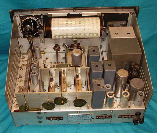
Using modern test equipment really makes performing an IF/RF alignment fast and easy. I now use synthesized signal generators, digital frequency counters, digital oscilloscope and a ME-26D military VTVM. With synthesizers, accurate frequency setting is just a matter of "punching in" the frequency and amplitude. Accuracy is unparalleled and there is no drift. I know in 2013 I was still using the HP606B as a signal generator and an old Simpson VTVM.

For this IF /RF alignment I'll be using modern (or fairly modern) equipment,...the HP3325A Synthesizer Function Generator for the IF alignment (goes up to 20mc.) For the RF alignment I'll use the FNIRSI DPOS350P RF Generator-Synthesizer (goes up to 50mc,) also this same device provides a DFC, DVM (works with the 'scope channels) and limited spectrum analyzer functions (unfortunately, no tracking generator.) The VTVM is an older style that was found in NOS condition,...the military HP ME-26D (basically a militarized HP-410-D.) Although the ME-26D is a relatively old vacuum tube piece of test gear, the analog meter movement when aligning for "peak" adjustments is very easy to see. While modern DVMs with visual digital to analog equivalents can be used, the old ME-26D has a large meter that makes setting peak values easy.

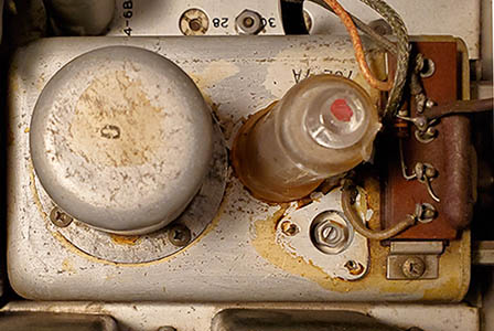
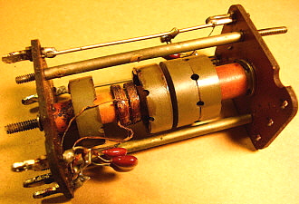
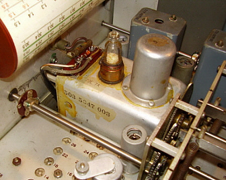
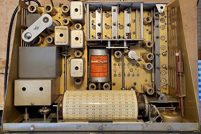
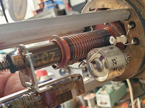
Crystal Oscillator Crystal Socket C adjustment - The procedure is, with power off, remove one crystal, select the Band that uses the removed crystal, measure the socket capacitance using a C-meter, adjust C167 (XTAL) for 32pf. I've never been able to get this procedure to actually work. I've used two different types of digital C-meters and neither one will show much C change as C167 is adjusted. I just assume that if I can adjust all of the Crystal Oscillator trimmers and all of the Crystal Oscillator frequencies are correct, then C167 must be adjusted close enough. It's possible that a crystal and Band has to be selected where the crystal is only used on that Band. I didn't verify that the crystal I removed wasn't used both as a fundamental and a harmonic - next time I'll try that.

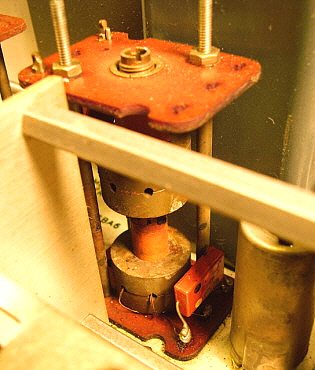
Crystal Oscillator Trimmers - I must not have adjusted these in 2013 because about half of them were set way too low. These shouldn't be set higher (more negative) than -2.0vdc but some were way below -1.0vdc.

IF Adjustment - I probably didn't use the detuning network back in 2013 because, although T104 was pretty close, T105 was way off and T106 was a little off. T101 was close. BFO close.
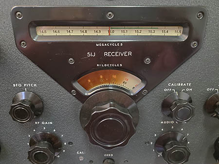
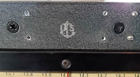
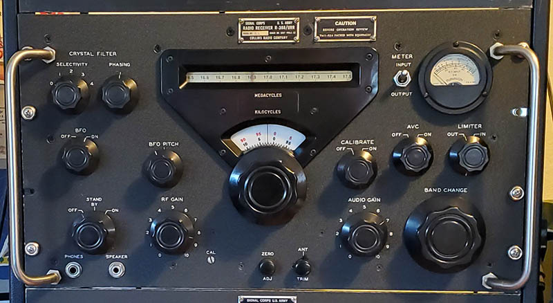
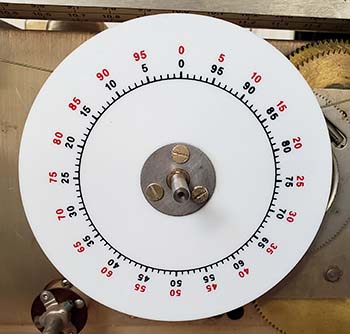
PTO versus KC dial - I must have set this up correctly a few years ago. 6.00mc set exactly 0.00 on the KC dial with the fiduciary straight-up indicates 2.5002mc output f from the PTO.

Vari-IF Tracking - The variable IF wasn't off by very much. But a slight tweaking was necessary on all of the adjustments.

RF Tracking - As expected, since I probably didn't use the correct dummy antenna back when I performed the earlier alignment, the RF stage adjustments were quite a bit off. The dummy antenna will allow a fairly consistent impedance on the Antenna input as the frequency is changed. Except for the RF stage adjustments, all other adjustments were fairly close.

Summary - Since SN:9108 worked quite well before the alignment, I didn't really expect to find any of the adjustments to be radically off. The Crystal Oscillator trimmers were off but anything under -2.0vdc is probably okay. I set them all to -1.9vdc. T105 was off quite a bit which was unexpected but I probably didn't use the detuning network in 2013. PTO was right-on but I might have reset the KC dial just a few years ago. Vari-IF only needed a little adjustment. Only the RF stage was off and that was probably due to using a different type of RF signal generator, actually a synthesizer, and using the correct dummy antenna. What about 
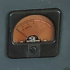
post-alignment performance? Tuned in Trenton Military on 15.035mc USB, went to 15mc WWV and the CL meter indicated +50db and the tuning was right-on 0.00kc with the fiduciary straight-up. Went up to 15M and heard a ZL station on SSB about Q5 S6. 20mc WWV indicated +40db exactly on 20.00mc with the fiduciary straight-up. I'll need to do some more listening,...this was right after the alignment was completed. These stations were heard about 1100hrs PST Nov 27, 2025. In the afternoon, I tuned in XSG 16.898mc, this is a Chinese Marine CW Beacon out of Shanghai. It's fairly difficult being much weaker than XSQ, the other Chinese CW Marine Beacon located in Guangzhou, China (XSQ is on 16.880mc and on 16.850mc.)


Continue to Part 4              Go Back to Part 1                        Go Back to Part 2                               Return to Home Index


Radio Boulevard
Western Historic Radio Museum

 Vintage Radio Communication Equipment Rebuilding & Restoration Articles,

 Vintage Radio History and WHRM Radio Photo Galleries

1909 - 1969

- 60 years of Radio Technology -


This website created and maintained by: Henry Rogers - Radio Boulevard, Western Historic Radio Museum © 1997/2026