|
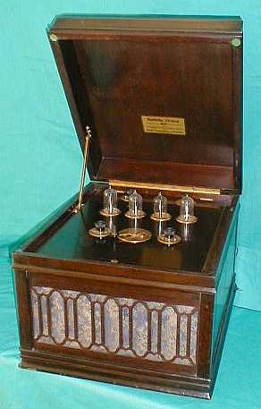
Receiving Transformers aka:
Loose Couplers
Before
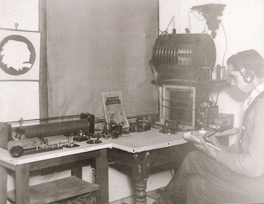
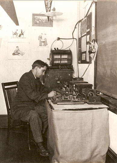
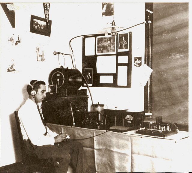
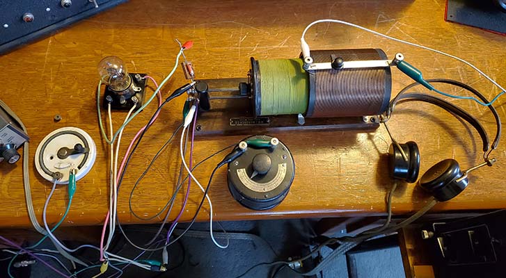
1917, most receivers and transmitters consisted of the various
components placed (or mounted) on a table with inter-connecting wires to
form the circuitry needed. Since experimenting was an essential
requirement for the amateur operators of the day, the ability to try
various "hook-ups" was aided by these "easy to modify" station
component interconnections. The receiver's Loose Coupler provided the user with the
ability to crudely tune in signals and to somewhat control the
selectivity of his receiver.
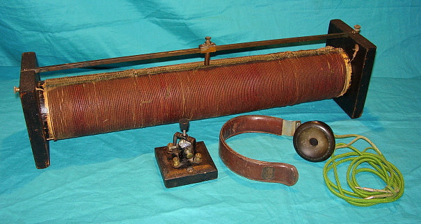
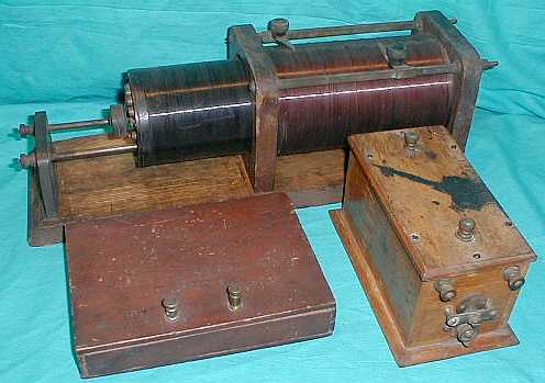
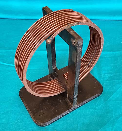
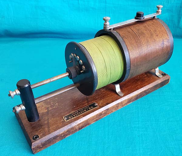
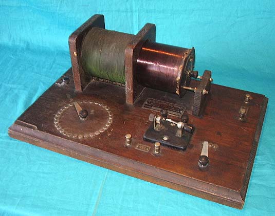
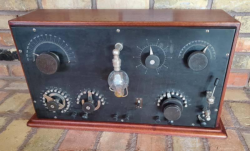
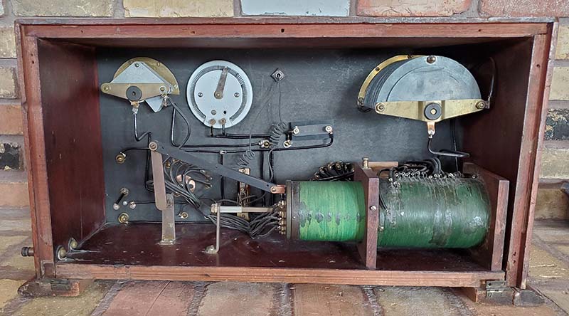
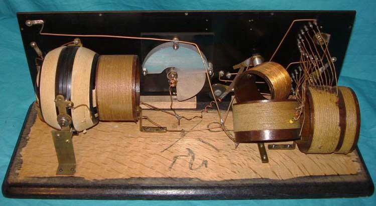
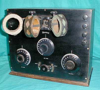
The larger coil is the Primary
Inductance and the antenna and ground are connected to this coil. The
slider roughly tunes the antenna load and primary inductance to resonance for whatever frequency it
is desired to receive by reducing the number of turns in the primary
and, depending on the connections, may short the "dead turns" to ground.
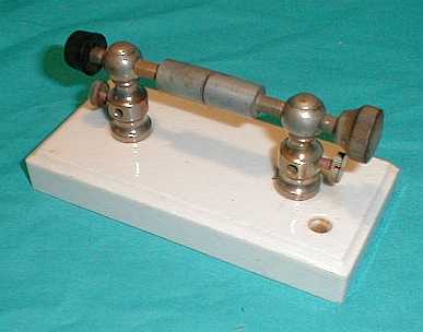
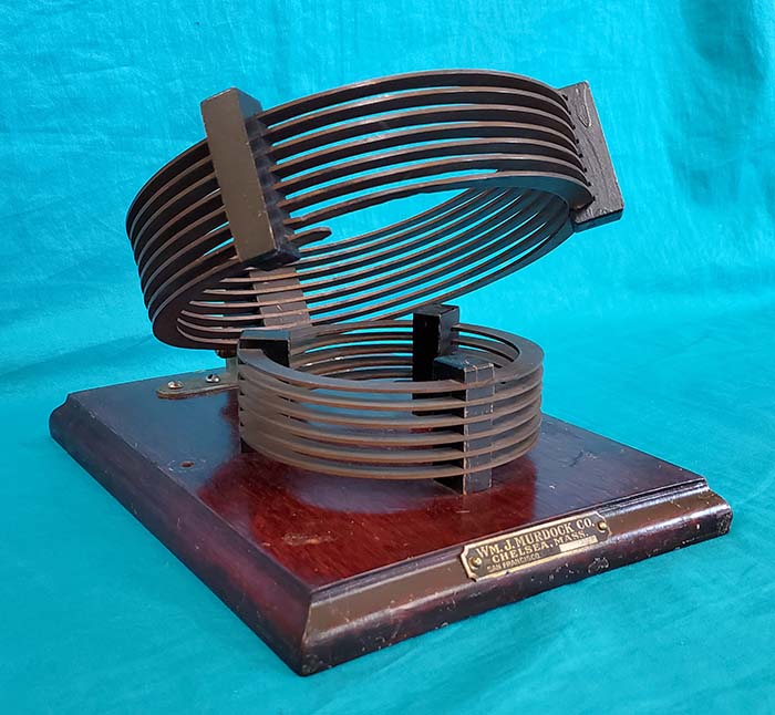
The smaller coil is the Secondary Inductance and this coil is tapped at
various numbers of turns that are brought out to the contact point
switch. The contact point switch roughly tunes the secondary to
resonance at the
frequency that is to be received by reducing the number of turns on the
secondary coil and depending on how it's connected may also short out
the "dead turns" to the coil return or to ground. Early
"hook-ups" depended on the mutual and inherent capacitance of the loose
coupler coils for the ability to tune to resonance just by varying the parameters of the
inductors
involved.
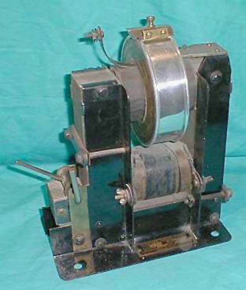
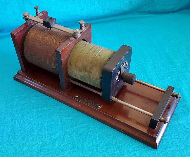
By sliding the Secondary into the
Primary, "Tight Coupling" between the Primary Inductor and the Secondary
Inductor will result. Tight Coupling produces stronger signals but with
a very, very broad bandwidth. By withdrawing the Secondary, "Loose
Coupling" between the Primary and Secondary is achieved. Loose Coupling
results in greater selectivity, at the expense of signal
strength. "Loose Coupling" and the resulting "narrow" selectivity are
certainly subjective terms from the time period. The typical bandwidth to be
expected with "Tight Coupling" would be about 1000kc at around 400
meters - yes!, that's 1 megacycle! This isn't an exaggeration - the bandwidth is extremely broad.
With "Loose Coupling" about the best selectivity or bandwidth to be
expected would be about 150kc but it would be dependent on the signal
levels involved. Before WWI there wasn't any commercial high power
broadcasting so there were only a few stations on the air and these were
all low power stations that weren't on the air continuously.
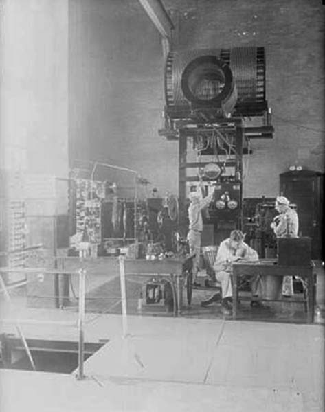
Most of the Navy transmitters being used at the time were operating
below 500kc and on down into the VLF region of the spectrum. The part of
the spectrum from 600kc up to 1500kc was very different at that time with mostly
experimental stations operating. Hams were operating from 1500kc on up. The
Loose Coupler's broad bandwidth with relatively good sensitivity gave the
operators the best chance of hearing a
signal. Today, using "Tight Coupling" with a Loose Coupler tuner will
result in hearing ALL of the nearby AM BC band stations - simultaneously!
Since you need a good antenna because you're using a mineral detector,
this large antenna compounds the selectivity problem resulting in the
usual Loose Coupler experience of hearing nothing but AM-BC stations
regardless of the tuning or coupling involved.
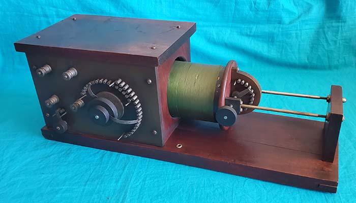
However, varying the proximity of
the Secondary Coil to the Primary Coil to vary the coupling will also change the mutual and
inherent capacitance so the desired "tuned" LC frequency resonance
changes if the
coupling position is moved. The proper tuning procedure was to set the
desired coupling
first (this just required an estimate on the operator's part on how much
selectivity would be needed.) Then tune the Primary using the "slider" and Secondary using
the "tapped contacts" for resonance at the desired frequency.
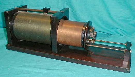
As more and more stations began transmitting greater selectivity was needed in the receiver.
This required "very loose coupling" that was achieved by withdrawing the secondary out
even more. Since this also reduced received signal strength, it became
of paramount importance that exact tuning of both the primary and secondary circuits
be accomplished. This had the additional benefit of slightly increasing
selectivity (not that it really helped that much.) More
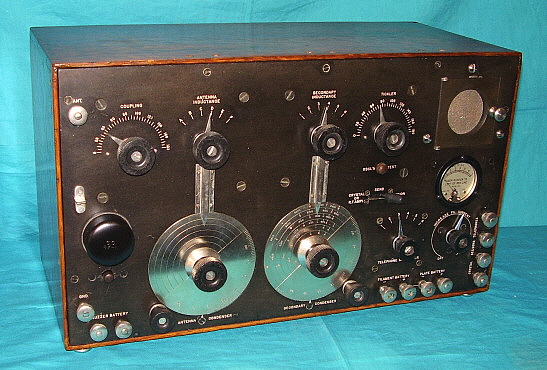
elaborate receiving set-ups would add air variable condensers to provide
easily adjustable and exact "tuning to resonance" of the Primary and
Secondary Inductors while allowing the coupling to remain "loose," that
is, the Secondary set in an
extended position.
To create a Loose Coupler receiver,
a mineral detector was added in series with the Secondary Inductor to
the 'phones. The 'phones return was to the other end of the Secondary
coil. The addition of a small telephone condenser, which was sometimes connected across the
'phones, would filter out the RF and maybe provide better audio response.
Phone condensers couldn't have a large value of capacitance as this
would tend to limit audio highs making copy difficult. Using just
mineral detectors required a strong signal input and the only method
available at the time was to use the largest antenna possible. Large antennas and excellent "earth" grounds
were an absolute necessity. If a vacuum tube grid-leak detector was
used instead of a mineral detector, sensitivity would increase
tremendously. However, as more and more stations began transmitting, the
lack of selectivity (much more apparent as the sensitivity was
increased) became a serious drawback to using a Loose Coupler as the
station's receiving tuner. Additionally, most hams were using
damped-wave spark transmitters that produced notoriously broadband
signals that would prevent reception of any other stations by other
nearby hams.
The era of the Loose Coupler receiver
ended for hams in the early-1920s as commercial radio broadcasting
started up. Also, at the same time, damped-wave spark transmitters were
being replaced with vacuum tube oscillators producing continuous wave (CW)
signals and vacuum tube receivers using
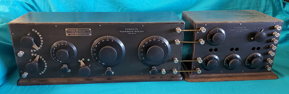
regenerative detectors were becoming popular. It was certainly possible to
use the Loose Coupler as a tuner and connect its secondary in series
through a tickler coil to the
grid of a vacuum tube detector and then connect a variometer
in series (and wired to invert the phase relationship) between the tube plate, the earphones and the B+ battery, then
place the variometer close to the tickler coil thus creating a "positive
feedback" or
regenerative detector receiver for CW reception - this really will work.
Go to "Spherical Audion Receiver" article for details on the "how to." Use the
Home-Index below to navigate. Even though that set-up was possible,
as detector circuits became more and more sensitive and as commercial radio
broadcasting became more and more popular, the very poor selectivity of the
Loose Coupler became more and more of a problem. By the early-1920s,
nearly all hams had moved to much more efficient and much more selective RF tuners.
Using a Loose Coupler Receiver
Today - As
commercial AM Broadcasting started up in November 1920, growing both
rapidly and tremendously, the loose coupler soon became virtually useless. By
the mid-twenties, hundreds and hundreds of broadcasting station were "on
the air" and by 1925 the "Broadcast Band" had been established from
550kc up to 1500kc. If anything put the Loose Coupler in the "obsolete
bin" it would have been commercial AM Broadcasting. The lack of selectivity,
even at the loosest coupling, couldn't separate the broadcast stations
and any weak signals were lost in the perpetual interference from very
powerful broadcasting signals. At that time, hams were mostly around 200
meters or 1500kc, that is just above the broadcast band. Interference, if the AM BC
station was nearby, would dominate the receiver no matter where it was
tuned or how loosely coupled it was.
Today, we really can't experience
what it was like to use a loose coupler receiver in a low noise, no
high-power interference environment that allowed the early user to search for
the very faint signal of some ham's rotary spark gap station in operation on 200
meters. Nowadays, ALL that can be heard will be the AM BC band. On top
of that, the AM BC band now extends past the 200 meter mark, up to
1700kc. My experimenting with a loose coupler tuner and a vacuum tube
detector has shown that I had to tune lower than 300kc to escape AM BC
interference. At the upper end of the loose coupler tuning range, about
1500kc, there was no escaping the interference. So, today using a loose
coupler receiver virtually all that can be received will be AM BC signals.
At one time, Loran C "Master Station M" was located in Fallon,
Nevada - just 60 miles east
of my QTH. "M" operated on 100kc at 400KW. I could
easily receive "M" using a loose coupler with a crystal detector
with no AM-BC interference (and "M" was LOUD, even with a crystal
detector.) Unfortunately, all Loran C operations were
shutdown in 2008 (Loran E is now in operation, 100kc 400KW from
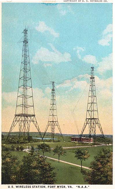
Master Station "M" in Fallon, Nevada - 7-2024.) I haven't tried to use my Arlington-type LC to see if it's possible
to receive the USN sub-comm stations on 24kc. Though these stations
operate at incredible power levels and produce very strong signal
levels, the MSK mode of operation does require some type of heterodyning
to really detect what's going on with the signal. |