Radio
Boulevard
Western Historic Radio Museum
Vintage Ham Gear - aka Older Amateur Radio Equipment
from 1929 up to the 1950s
|
Radio
Boulevard
Vintage Ham Gear - aka Older Amateur Radio Equipment from 1929 up to the 1950s
|
|
| So much of the ham gear that was in the two sections of "Pre-War Ham Gear" and the one "Post-War Ham Gear" was covered elsewhere on the website. The Hammarlunds are extensively covered in several articles on this website. Hallicrafters, also, is covered in many write-ups covering specific models. National HRO receivers and NC-100 Series receivers are extensively covered in multi-section articles. It really seemed that a lot of what was covered in Pre-WWII and Post-WWII Ham Gear was really repetitious and was consuming a lot of the limited data space I have available. So, I've decided to consolidate all of the equipment that isn't covered anywhere else on the website and create a "Vintage Ham Gear" page that profiled that gear. I tried to group the equipment by manufacturer rather than chronologically (as it had been before.) |
|
Pre-WWII Ham Gear |
|
|
|
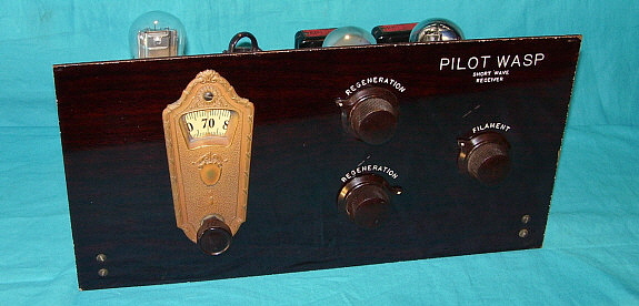
Pilot Electric Manufacturing Company - "Pilot Wasp" - Model K-101 Though Pilot's advertising claimed they had been in business since 1908 and the company had used several different names during that time, "Pilot Electric Manufacturing Company" was officially founded in 1922 by Isidor Goldberg in Brooklyn, New York. Pilot Electric Manufacturing Company also claimed to be "The World's Largest Radio Parts Plant" in the twenties and they did build all of the parts supplied with their kits. Some of the famous employees of Pilot were Robert Kruse, Alfred Ghirardi and John Geloso. David Grimes was a Contributing Editor for "Radio Design" - Pilot's magazine. Though not the first Shortwave receiver kit offered by Pilot, the three-tube "Wasp" was certainly their first really popular Shortwave receiver kit. In 1928 the selling price was $21.75 including the coils. The "Wasp" was designed by Robert Kruse and Milton B. Sleeper. The plug-in coils selected the tuning ranges that covered 500 meters to 17 meters or about 600kc up to 17.6mc. A complete coil set featured five coils each with color-coded handles for identification. The three tubes were usually 201-A and the circuit used a regenerative detector followed by two stages of transformer coupled AF amplification. The kit included detailed instructions along with an assembly drawing. Builders were warned to adhere to the wiring layout shown on the drawing or performance would suffer. The circuit was built on a bakelite board for the chassis and a mahogany colored bakelite panel. The "Wasp" was introduced just as Shortwave Broadcasting was beginning to grow and everyone wanted to tune in to stations located in foreign countries. The "Wasp" was very popular and soon spawned a newer, more sophisticated successor, the "Super-Wasp." |
|
|
|
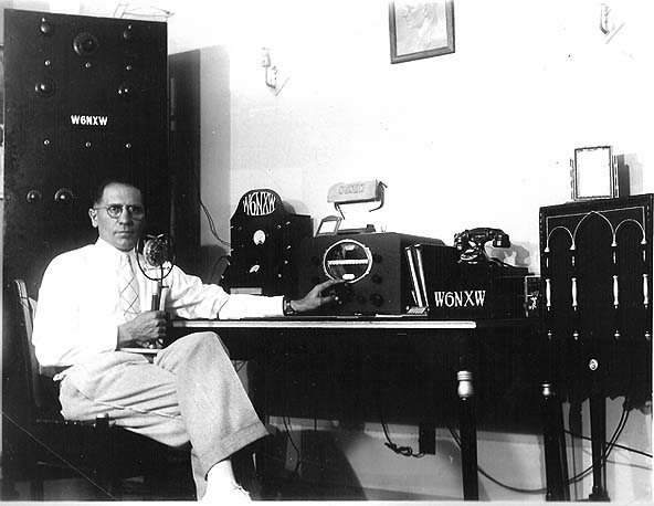
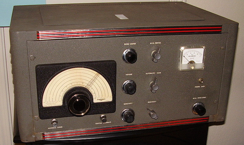
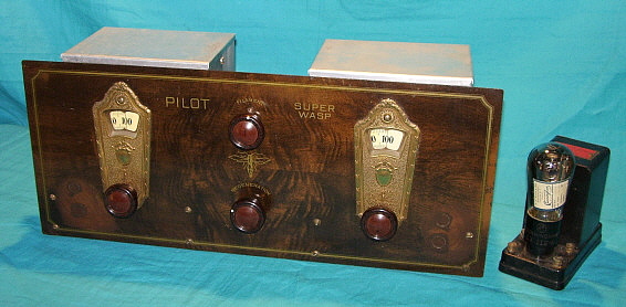
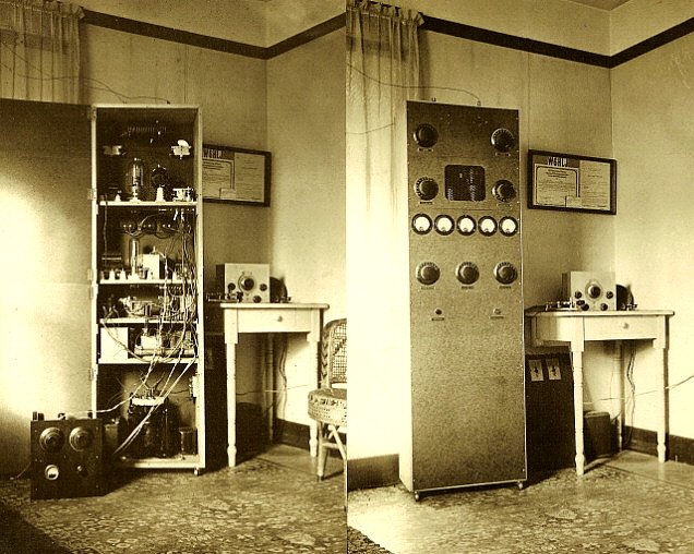
Pilot Electric Manufacturing Co., Pilot Radio & Tube Corp. - "Super-Wasp" Battery Model K-110 The four-tube "Super-Wasp" kit was introduced in early-1929 and featured a screen-grid tube for an RF amplifier along with regenerative detector and two-stage AF amplifier. The "Super-Wasp" kit sold for $29.50 including the five pairs of plug-in coils providing tuning coverage from 500 meters to 14 meters or about 600kc up to about 21.5mc. Detailed instructions, including a full size blue print, made assembly relatively easy and assured that each "Super-Wasp" could perform pretty much as expected. Since these were kits though, build quality was highly variable and dependent on the assembler's experience. Pilot's magazine "Radio Design" was always including updates along with suggestions for improving performance, consequently most "Super-Wasp" receivers found today will have some modifications or non-original parts. The stock circuit used a type 22 screen-grid tube as an RF amplifier, a 201-A as a regenerative detector and a 201-A tube as the first AF amplifier and a UX-112A as the second AF amplifier. The user could substitute a 201A for the last audio stage and reduce the plate voltage and bias voltage if a UX-112A was not available. To the right of the K-110 is one of the modular units Pilot called "Redi-Blox." This one is a single-stage transformer input audio amplifier using a type UX-112A tube. This module could be added for a third audio amplifier stage if the user thought it necessary. Pilot offered "Redi-Blox" assembled modules in the late twenties to enthusiasts to help ease the mechanical side of kit building. Around the time that the "Super-Wasp" was introduced, Pilot changed the name of the company to "Pilot Radio & Tube Corporation" (April, 1929.) "Super-Wasp" receivers were quite popular and sometimes were found in ham shacks of the late twenties and early thirties. By today's standards, the "Super-Wasp" is a very primitive shortwave/ham receiver but performance can be surprisingly good if the operator has patience and is willing to put in a few nights learning how the "Super-Wasp" works. All controls interact with each other making tuning sometimes tedious and demodulating SSB or CW signals requires the detector to be oscillating which increases the instability. However, patience will be rewarded and it is fun to use a 1929 battery-operated receiver to monitor one of the many AM ham nets on 80 meters, especially when running the audio to a vintage horn speaker - talk about "broadcast quality audio" - well, 1929 style anyway! When examining vintage QSL cards that date from about 1930 up to about 1934, it's surprising how many times the Pilot Super Wasp is listed as the station receiver. In fact, the header photo showing station W1AVJ has a Pilot AC Super Wasp on the desk. The AC Super Wasp is profiled next,... |
|
|
|
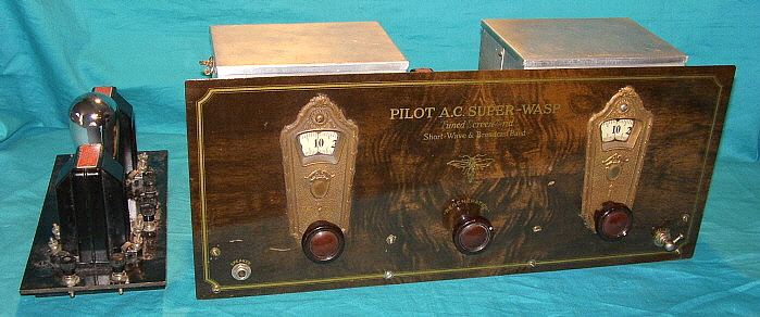
Pilot Radio & Tube Corporation - A.C. "Super-Wasp" Model K-115 The improved "Socket-Power" A.C. "Super-Wasp" kit was available by late 1929 and sold for $34.50. The tubes used were a type 24A cathode and screen grid tube for the RF amplifier, a cathode type 27 for the regenerative detector and two 27s for the AF amplifier. All of the tubes operated on 2.5vac at 7 amps for the heaters and the K-111 power pack supplied all of the A+ and B+ voltages required. The K-112 power pack can also work with the A.C. Super-Wasp even though it was for a receiver that used 45 tubes (just don't use the +HV and ground the B-/CT return to power up the A.C. Super-Wasp.) The lower right-hand switch was wired back to the K-111 to provide an "on-off" switch at the receiver (other power packs provided the same option.) The first AF amplifier was a resistance coupled amplifier while the second AF amplifier was transformer coupled along with an output transformer. There was a considerable design effort put into the A.C. Super-Wasp to eliminate hum since most operation was going to be using earphones. Hum reduction was one of the reasons for the RC coupled AF stage. Pilot also stipulated that only their own Pilotron tubes would perform correctly in the A.C. "Super-Wasp." Pilot plug-in coils are used for five tuning ranges covering 600kc up to 21.5mc. Shown to the left of the K-115 is the K-120 Audio Booster Unit, another Pilot module (though it is not called "Redi-Blox") for builders, that could be used if loud speaker volume was desired. All of the Pilot "Wasp" and "Super-Wasp" receivers found today will vary greatly in the quality of workmanship. Since these receivers were kits, the assembler may have had little or no experience in soldering, wiring or mechanical building. As a result, don't be hasty to judge a poor performing set as a "bad design." Check the receiver over carefully. An inspection of the soldering will usually be a clue into the level of workmanship you will encounter in your receiver. When everything is correct, the Pilot "Wasp" and "Super-Wasp" receivers are fine performers considering their vintage and a lot fun to use. |
|
National Company, Inc. - SW-5 "Thrill Box" The National Co. started in business manufacturing toys and parts in 1914 (as the National Toy Co.) By the mid-twenties, National Co., Inc. had long ago dropped the "toy" from their name and was supplying parts for the Browning-Drake BC receiver kit and also started producing radio parts. Mechanical Engineer James Millen joined the company as General Manager and Chief Engineer in 1928. Millen was a Stevens Institute graduate and an enthusiastic ham so it was natural that he guided National into the ham/shortwave receiver market. This move happened to coincide with the new and developing shortwave broadcasting which was becoming popular with a new audience, the "shortwave listeners" or SWLs. National introduced the SW-5 "Thrill Box" in 1930. The name "Thrill Box" implied how exciting it was for the SWLs to receive foreign broadcasts direct from around the world. Though primarily designed for the SWL, the SW-5 could also be found in many ham shacks in the early 1930s. It was an expensive receiver with selling prices usually over $100 with the power supply. Robert Kruse, of the Pilot Wasp and Super Wasp fame, was involved in some of the design work in developing the SW-5 through his laboratory in Hartford, Connecticut and with several visits to National's lab. The circuit was a five tube receiver using a regenerative detector (24-A) with TRF stage (24-A,) audio driver (27) and P-P audio output (2-27.) The coil sets initially covered 1.5 to 30MC in five sets but eventually several other coil sets were added along with bandspread coil sets. The first coil sets were color coded for identification. The receiver was powered by a separate power supply that provided the 2.5vac filament voltage and approximately 180vdc B+. The tuning dial was illuminated and projected onto a frosted viewing screen. The left hand control is the regeneration and the right hand control is an antenna trimmer adjustment. There was a "Battery Model" SW-5 available and a special "Low Drain Battery Model" that used 2-volt tubes that ran on an air-cell battery that was supplied with the receiver. There was also a "Special Broadcast Model" that had P-P 45 tubes in the audio output. Early SW-5 receivers may have been available as a kit similar to the Pilot Wasp sets. Some National receivers (SW-5 and SW-3 mainly) will have a decal or label stating that the unit was built at Jackson Research Laboratory, however this was a company that was solely owned by National and was located adjacent to the National plant. Labeling receivers as built at Jackson Labs was a form of product protection that was the result of a broad suit brought against all radio manufacturers by Cardwell sighting the use of their variable condenser patent. The suit was not successful but National kept the Jackson name around for a while afterwards. Go to "Military and Commercial Communications Gear Part 1" to see and read about the U.S. Navy RAD-2, a National SW-5 built for shipboard use in 1932. |
|
National Company, Inc. - AC SW-3 (AC Version) National introduced the three tube SW-3 in 1931. It was a regenerative detector with RF amp and AF amp utilizing plug-in coils. There was an AC model that ran off an accessory National power supply and a DC model that was operated with batteries. The DC model also had a switch under the lid to disconnect the A battery. James Millen and the National engineers put considerable effort into the SW-3 design to achieve maximum performance in a three-tube regenerative receiver. Shielding was carefully developed as was the coil design to allow both general coverage coil and amateur bandspread coils to be used. The end result was a little receiver that had amazing capabilities and was very stable at the point of oscillation. The SW-3 had a long production life and was produced in fairly large numbers. Coil sets were available for a wide range of frequencies from longwave to 30MC, along with the bandspread sets for the amateur bands. Later, the SW-3 became so popular as a stand-by receiver that National even offered it after WWII for a short time as the SW-3 "Universal" using three octal tubes. Parts and coils were available from National up well into the fifties. Probably the best testament to the SW-3 performance is in a photograph that is in a mid-thirites QST showing a ham station that used a full-size rack Collins built transmitter along with the station receiver - the SW-3 - certainly not typical but it says something about the SW-3 performance capabilities. |
|
|
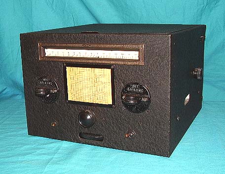
National Company, Inc. - FB-7, FBX, FBX-A In March 1933, National introduced the FB-7, a seven tube scaled-down and economically-built version of the AGS, offered so hams could buy a superheterodyne at a realistic price, (about $65 with accessories.) The FB-7 eliminated the RF amplifier and the AVC circuit of the AGS. Additionally, the 6.3 volt tubes of the AGS were replaced with 2.5 volt tubes in the FB-7. The extensive use of aluminum found in the AGS was replaced with sheet metal chassis and cabinet in the FB-7. The receiver used plug-in coils that are similar to the AGS coils. There were six general coverage coil sets available and identified by the prefix "FB" and the letters AA, A, B, C, D and E (AA was the 10M coil set covering 18mc to 34mc.) Or, the ham could purchase a bandspread set of coils (ID prefix "AB") for 160, 80, 40 and 20 meter coverage. The FBX Single Signal model added a crystal filter to the receiver with the controls accessible on the right side of the receiver cabinet. The FBX came out after James Lamb's article in QST about Single Signal receivers and crystal filters. The IF was 500kc for the FB-7 and approximately 495kc for the FBX depending on the particular crystal used in the Crystal Filter. The BFO frequency control is a knob on top of the BFO coil can and is accessed under the lid. A matching National pre-selector was available, the model PSK, that added a TRF stage to reduce the image problems but it required its own set of plug-in RF coils. The PSK was usually bolted to the right side of the FB-7 using standoffs - long standoffs if it was an FBX so the operator could have access to the crystal filter controls. Though many hams preferred using earphones, the FB-7 would drive a loud speaker quite well with the proper power supply. At least three different models of AC power supply were offered that could operate any of the FB-7 receivers but the 5897AB was recommended since it provided sufficient B+ voltage to allow the type 59 audio output tube to develop sufficient power to drive a loud speaker - about +240vdc. Most of the 5897AB power supplies that were sold with FB-7 receivers have a tag on top stating the the 5897AB was "designed especially for the FB-7." An "A" suffix to the FB-7 or FBX designation denotes the use of National's improved IF transformers that utilized air-spaced trimmers rather than compression trimmers. The receiver shown is an FBX-A from 1934. The FB-7 and its variations were very popular and found in many ham shacks in the mid-thirties as evidenced by the examination of 1930s QSL cards. |
|
|
|
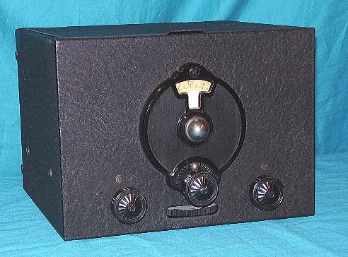
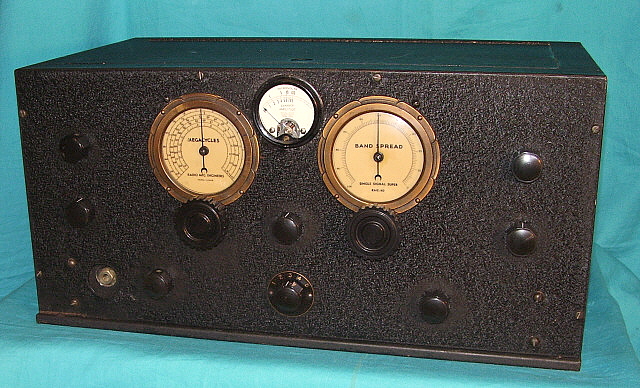
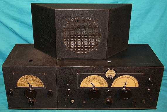
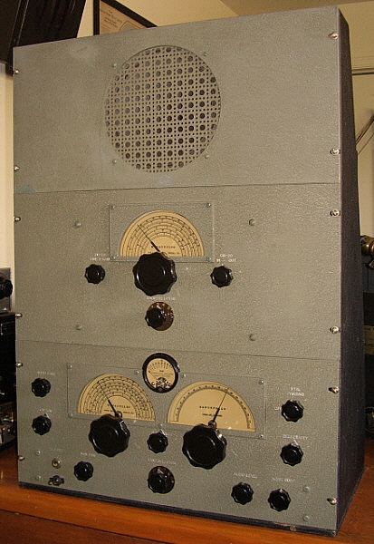
Radio Manufacturing Engineers, Inc. - RME-9D Radio Manufacturing Engineers, Inc. started in business in the early thirties, founded in Peoria, Illinois by two hams - E. Shalkhauser, W9CI and Russ Planck, W9RGH. Their first receiver, the RME-9 was designed in 1932 and was on the market by 1933. The RME-9 was a nine tube receiver with a single airplane-type tuning dial and an R-meter for measuring relative signal strength. The RME-9 featured a tuned-RF stage, two stages of IF amplification and a built-in power supply. The receiver was compactly-built onto a stout chassis made out of aluminum extrusion with the overall size of the receiver being quite small (19"W x 9"H x 10.5"D.) After some months of production and about 100 receivers produced, RME revamped the "9" and introduced the improved RME-9D. The RME-9D incorporated electrical bandspread and thus used two airplane-type dials with the R-meter between the two dials. Nine tubes were still used since the basic design remained unchanged. Five tuning ranges were provided with frequency coverage from .54mc up to 23mc. The tubes used were 58 (4), 57 (1), 2B7 (1), 2A5 (1), 24A (1) and 80 (1.) . Selling price was usually around $112 from discount houses. The RME-9D was produced from late-1933 up to the introduction of the RME-69 in November 1935. There are some minor variations that are encountered with different types of knob sets being the most common. This especially relates to the tuning knobs with the large "RME-69" type tuning knobs often found on late versions of the 9D. Like many "Depression Era" receivers, it is common to find examples of the RME-9D with modifications added. The tuning and bandspread dials are relatively small and the nomenclature is miniscule and difficult to read but the dial illumination does help. For its time, the RME-9D was a first-class receiver that introduced what became the "basic necessities" for amateur radio receivers - built-in TRF stage, Carrier Level meter, panel operated BFO, Crystal Filter and Bandspread tuning. Although not necessarily the first receiver to incorporate any of these individual features, the RME-9D was the first receiver to use all of the features together as "standard equipment" and with no external assemblies necessary other than the loudspeaker. This rapidly became more-or-less "the standard" for all communications receivers for the next two decades. The RME-9D shown in the photo is an all-original, late production version with a serial number of "431." RME receivers had a paper label on the bottom of the cabinet with the calibration date hand-written on it. The date on this receiver's tag is 9-12-1935. This is about two months before the introduction of the RME-69. Since this receiver is very late in the RME-9D production and has a serial number of 431 one can infer that the total number of RME-9D receivers built is probably around 500. The scant number of RME-9D receivers encountered today seems to confirm that production levels were very low. |
|
|
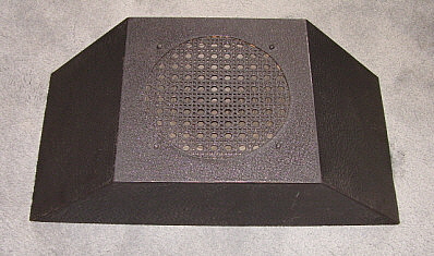
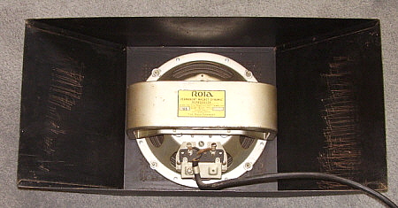
RME-9D Speaker - The RME speaker housing was an unusual trapezoid shape that allowed for a bench corner location to be used for the speaker and then rectangular equipment cabinets could butt against the speaker cabinet sides. The speaker utilized was an eight-inch Rola PM speaker with a large "wrap-around" magnet support structure. The transformer is a matching transformer that provides a 4000Z for the receiver output transformer impedance and an eight ohm impedance for the speaker voice coil. This same style of speaker housing was supplied for the RME-69 receiver although the Rola speaker was a more modern configuration with a much smaller magnet assembly. Luckily, a date is ink-stamped on the speaker frame - JUL 9 1935 - indicating that this speaker was probably purchased with the RME-9D. |
|
|
||
|
A popular RME accessory was the DB-20 Pre-selector, introduced in October 1936. It provided the user with two tuned RF stages ahead of the RME-69 with an advertised gain of 20 to 25 db along with reduction of images. When the RME-69 was used with a DB-20, three tuned RF amplifiers were in operation - sensitivity was incredible and images were no longer an issue. A VHF Converter was also available. RME also offered the DB-20 and the RME-69 installed into one very long cabinet. The matching speaker is mounted in an unusual trapezoid shaped cabinet that allowed for a bench corner to be used for the speaker location and then rectangular equipment cabinets could be butted against each side of the speaker cabinet. Early versions of this speaker cabinet used Rola speakers while late versions used Jensen speakers. In 1939, the RME-70 was introduced and the RME-69 was slowly phased out of production. About 6500 RME-69s were built from 1935 up to about 1940. Shown in the photo above is our 1937 RME-69 SN 1931 with its matching speaker and matching DB-20 Pre-selector. Serial numbers on early receivers are numerical and are probably actual sequential numbers for the quantity of receivers built. Around 1938-39, the serial numbering system was changed to a letter-number combination that probably represents sequentially numbered receivers within specific production runs with the production run identified by the letter used in the serial number. If you are aligning an RME-69 be aware that it has a decidedly different front-end with no trimmers to compensate for variations in the coil windings of the RF or Mixer sections. This was because the coils were all pre-tuned before assembly and all coils should be identical from receiver to receiver. Whether they have aged the same over the past 70 years is an unknown but most seem to have weathered time quite well. Since the alignment requires some special information, it is lucky that the quirky alignment procedure is in Rider's VOL. X. When aligning the RME-69, it will be noted that the adjustments for the LO are compression trimmer capacitors which are notorious for not "holding adjustment." RME, more than any other communications receiver company, believed that the "ham owners" of their receivers were "tinkerers" - the type that was always adjusting this or aligning that. The fact that the LO might need adjustment every few months didn't bother that sort of owner and apparently didn't bother RME either. The RME-69 by itself is a typical late-thirties performer, however when rebuilt and aligned, the RME-69 used with the DB-20 preselector is an almost unbeatable vintage receiver. It will be noted that some of the components used in construction are somewhat on "the cheap side." Also, it appears that several parts are just AM BC radio parts that were purchased to construct the receiver. Although Hallicrafters made their reputation on using purchased parts to construct their receivers, RME didn't have that sort of reputation. RME's style of advertising promoted the "engineering" side of design rather than the source or quality of the components used. Still, the RME receivers do perform quite well when rebuilt and aligned correctly. |
|
|
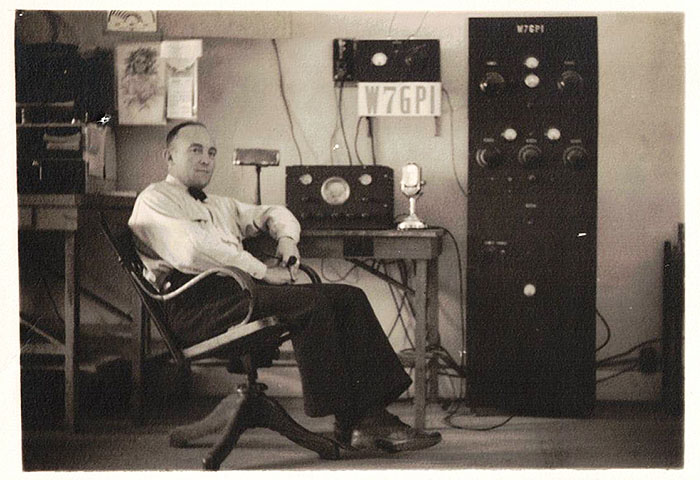
W7UIZ's RME-69LS-1/DB-20 Rack Mount In 1940, Gordon Harris became the youngest licensed ham in the state of Nevada at the age of 12. His father bought him this RME-69 with the LS-1 Lamb Noise Silencer along with the DB-20 preselector and matching speaker - all rack mounted in an RME table-top rack assembly. Quite a receiver for a young ham but Gordon was a genuine enthusiast. Gordon also became Nevada's youngest holder of a FCC First Class Radiotelephone License at the age of 16. He was hired by radio station KOH in 1944, when station manager Bob Stoddard couldn't find any FCC-licensed engineers available due to the demands of WWII. Gordon's "read-the-copy" test was a dismal failure. Those of us who knew Gordon's rapid-fire, whispery voice knew he'd never be an announcer on KOH. Instead, he was put to work at KOH for his technical abilities, working after school and on weekends. After WWII, Nevada went from the sixth call district to the seventh and Gordon's call became W7UIZ, which he kept until he became an SK in 2012. It's very rare for a ham to have kept his original receiver, especially over a 72 year period of time. I was given Gordon's old receiver by his son in 2015. The RME-69LS-1 is a very late version of the receiver with the BFO switch being a toggle switch located in the lower left corner of the panel. The Crystal Filter is the late version without the "series-parallel" function. In the lower right corner is the Noise Silencer control. The Lamb Noise Silencer was only used in a few receivers (with the Hallicrafters SX-28 being the best known.) The Lamb NS actually is a tuned-IF noise blanker that works quite well on both voice or cw. It required two extra tubes and one IF tuned transformer. The Lamb NS is built onto a small chassis (which also has the two IF amplifier tubes mounted on it.) The LS-1 version of the RME-69 uses a 6L7 and a 6K7 in place of the older two 6D6 IF amplifier tubes. The Noise Silencer uses a 6J7 and a 6H6. The DB-20 is a two-stage TRF preselector that was a very popular accessory for the RME-69. This version is rack mounted with a full size 19" front panel. The speaker panel uses the standard 8" Jensen PM speaker with matching transformer. All of the panels are .190" aluminum finished in gray wrinkle paint with engraved nomenclature. Normally, RME didn't provide any panel control information believing that the ham should know his receiver and know the functions of the controls without any nomenclature required. This rack mount RME-69 is somewhat of a departure from that belief and all control functions are well-identified with engraved nomenclature. Radio Manufacturing Engineers, Inc. was very successful during the 1930s and was certainly a true competitor to the "Big Three" (National, Hammarlund and Hallicrafters.) However, RME didn't evolve from their 1930s design concept and, after WWII, the company began to stagnate. With new ownership under ElectroVoice in the early 1950s, a few newer models emerged. The most famous was the very modern RME-6900. ElectroVoice sold the RME name to G.C. Electronics in 1962. The RME name faded away shortly after. |
|
||
|
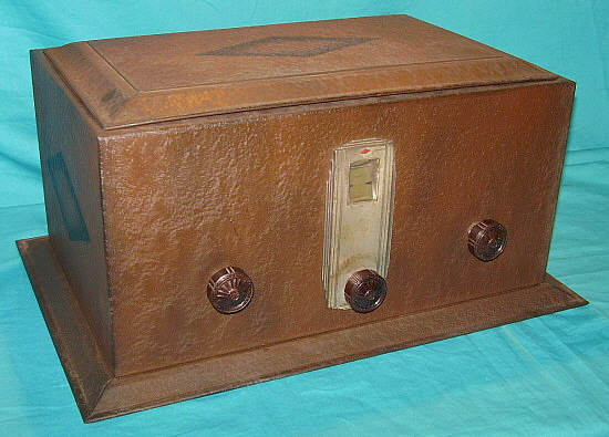
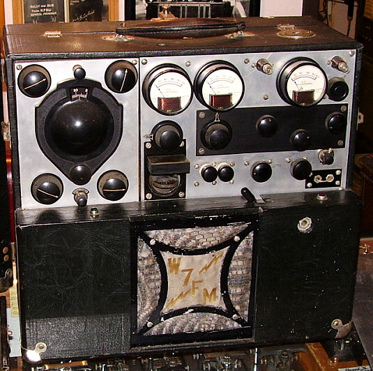
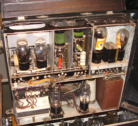
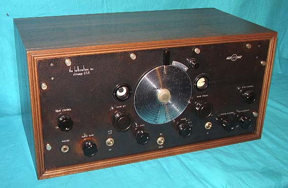
W7FM - Homebrew Transmitter-Receiver (TX-RX) Some homebrew ham equipment was so well-engineered and so well-built that in some cases it's difficult to image that the gear isn't commercially built. It's extremely fortunate that some former owners have had the foresight to save and preserve these superior examples of amateur engineering. The W7FM Transmitter-Receiver is an amazing example of efficient packaging and shows the creativeness that was necessary during the Depression to build quality, compact, useable gear. W7FM, Don Thorton of Spokane, Washington, decided to build a two-tube regenerative receiver and a four tube (crystal controlled oscillator, buffer and parallel power amplifier) CW transmitter both with their own individual AC power supplies. Not particularly unusual in the early thirties. But how about installing everything into a 1927 Kemper Radio Company K-5-2 cabinet. The original Kemper K-5-2 was a portable five tube battery operated TRF radio in a leatherette covered wooden box that featured a removable front cover and removable back cover. W7FM built the two AC power supplies into the lower section of the K-5-2 cabinet where originally a folded horn speaker and battery storage was located. In the upper section of the cabinet as viewed from the rear (shielding removed for photo) on the right is the two tube receiver and to the left is the four tube transmitter. What is amazing about the packaging is that full shielding was accomplished by building the entire TX-RX into a metal box that fits exactly into the Kemper K-5-2 cabinet. The entire receiver and each section of the transmitter are contained in shielded compartments. Looking deceptively light-weight, this TX-RX runs the scales up to an incredible 70 pounds! Full metering is provided with three panel meters. Six plug-in coils are required with two needed for the receiver and four for the transmitter. There are two complete sets of coils that were built for the TX-RX. Behind the speaker grille (with the "W7FM" embroidery) is an armature-pin speaker for receiver output. Separate receiver and transmitter antenna inputs are used. The receiver uses a type 27 for the regenerative detector and a type 47 for the audio output. The transmitter uses a 59 crystal oscillator, a 46 buffer stage and a pair of 45s in parallel. A hand-drawn schematic of the transmitter shows parallel 10s but Don Thorton probably decided that the 7.5vac filament voltage required for the 10s was impractical and went with 45s to keep all of the filament voltage requirements at 2.5vac. An 83 is used for the transmitter power supply rectifier and a type 80 is used in the receiver power supply. Note that the receiver power supply is built from old RCA Radiola parts. Thorton probably built his TX-RX around 1934 judging by the circuits and the parts used. Don Thorton became an SK around 1940 and his son, Doug, was too young to remember his father using this TX-RX. Doug himself tried it out when he was in high school. The receiver worked fine and a friend listening on another receiver in town "thought" he copied the signal from the transmitter. Doug didn't have a license, so he didn't perform more than just the one test. Since then, the TX-RX has not been powered-up. Doug Thorton donated his father's homebrew TX-RX to the WHRM in October, 2010. Stay tuned for updates on this unit's functionability as we'll attempt to have it running soon. |
|
W6HLJ's Homebrew One Kilowatt Transmitter - 1934 |
|
|
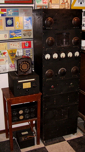
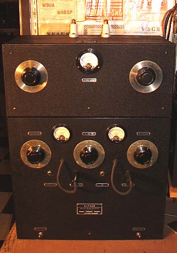
Alvin Norberg, ex-W6HLJ, began building this professional looking transmitter in 1934 upon graduating from Manteca High School. He worked as a laborer for Spreckles Sugar Company to earn the money to buy the parts needed. A few years later he was graduating from UC Berkeley as a BSEE (1939.) The transmitter construction is entirely made out of wood and masonite. Each section of the transmitter is built onto a wooden base (with the masonite front panel attached.) Each section slides into place on guides. The cabinet is made out of 1"x12" pine painted black. Al tried to duplicate the look of a Bell Labs rack out of wood. Symmetrical layout with matching meters, function ID tags, 4" diameter knobs and purf-metal viewing ports added to the professional appearance. Al baked the wrinkle finish paint inside his mother's wood stove oven. Al said,... "When the transmitter was keyed all of the meter needles swung together and the mercury rectifier tubes flashed their blue light. When the key was held closed the plate of the final amplifier Heintz & Kauffman HK-354 would glow red! WOW!" Inside the transmitter the circuit is a crystal-controlled 6L6G oscillator that can be front panel switched to three different plug-in crystals. The buffer stage uses a Western Electric 211-D and the final amplifier is a Heintz & Kauffman "Gammatron" HK-354. The transmitter is CW only and originally ran 1 KW input power or about 700 watts output power. The PA plate condenser is homemade and was built by a machinist (the father of a friend) who made a gift of the precision made condenser. The plate transformer was a salvaged "peg-pole" transformer that was used to provide around 4000vdc on the plate of the HK-354. Unfortunately later in the transmitter's life, the original plate transformer was removed to lighten the total weight for easier moving. |
|
| Update for July 2013: Al Norberg, at the age of 97, is still a registered EE with the state of California. He recently (June 2013) donated his Speed-X bug that can be seen in the B&W photos and also the National Type-N dial that can be seen on his homebrew three tube receiver that is in the B&W photo. Unfortunately, the receiver was "parted out" years ago but building a duplicate is a possibility. The transmitter has been moved and is now at our new QTH in Dayton, Nevada. The top half of the transmitter is restored but the power supply section is still awaiting rebuilding before a test transmission could be made. Go to our webpage "Telegraph Keys" to see a close-up photo of the W6HLJ Speed-X. Navigation link in the index at the bottom of this page. |
|
|
|||||||||||
|
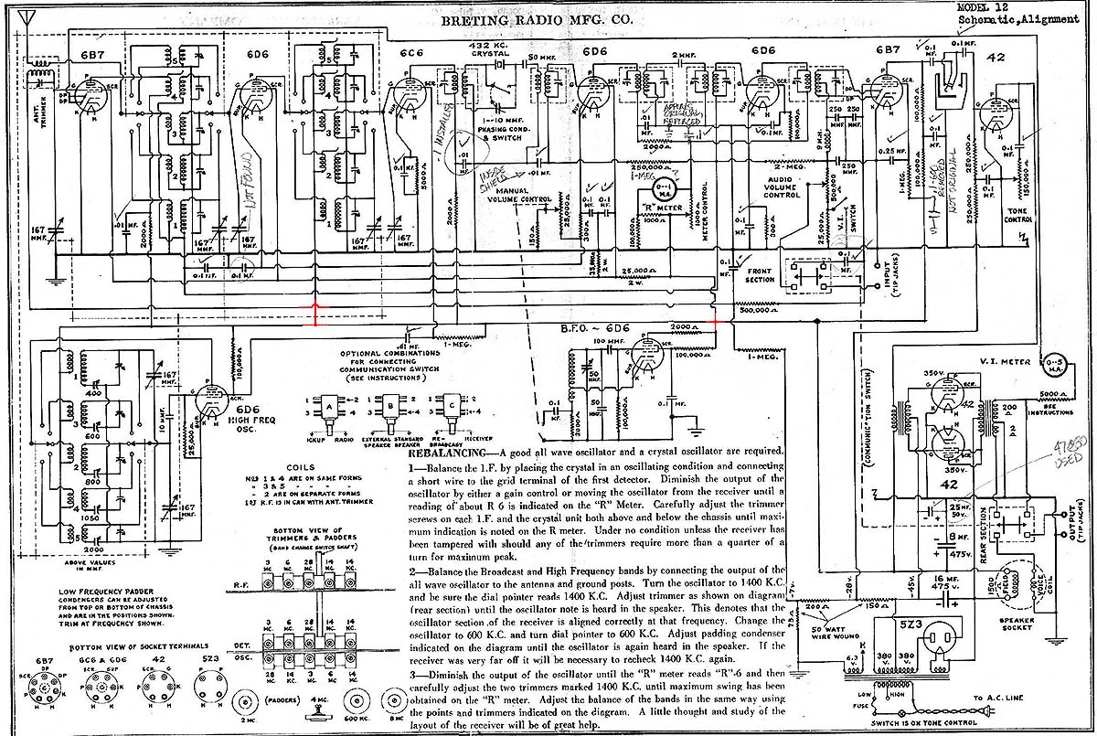
Breting Radio Manufacturing |
|||||||||||
|
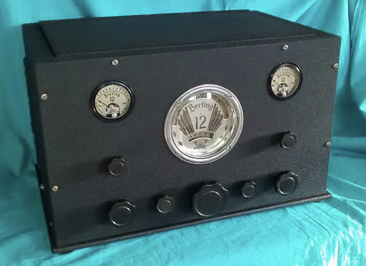
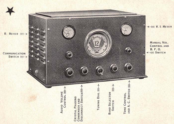
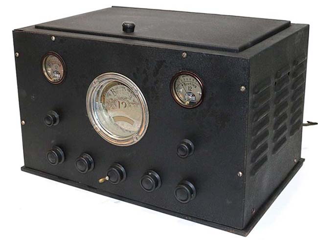
Paul J. Breting started selling communications receivers in 1935. Breting Radio Manufacturing didn't have the necessary RCA Superheterodyne license so their receivers were assembled at the exclusive "RCA licensed" Gilfillan plant in Los Angeles, California with Breting operating as a "sub-contractor" protected by Gilfillan's license. Breting was able to take advantage of Gilfillan's production processes, stock inventory and tooling while building his receivers. Ray Gudie, who was famous for the Patterson PR-10 design, was Breting's chief engineer. Gudie came over to Breting after a wage dispute with Emmitt Patterson. Gudie felt the success of the Patterson PR-10 should have warranted him a salary increase. The PR-10 was quite a popular communications receiver that sold very well but Patterson disagreed that it warranted a pay raise for Gudie. Patterson's disagreeable manner in the matter caused Gudie to resign and go to work for Paul Breting (both Patterson and Breting were located at the Gilfillan plant, so Gudie didn't have to go very far to be hired by Breting,..probably just across the hall.) The Breting 12 was Gudie's first major design for Breting and it was introduced in 1935. The advertising hype for the Breting 12 used the impressive description "Scientifically Correct D-X Radio" but exactly what that meant is vague. The list pricing for the Breting 12 shows several options. The receiver chassis without cabinet, meters or crystal (this meant the entire crystal filter unit, not just the crystal for it) was $135. The crystal (filter) could be added but not the meters for just the chassis with no cabinet for $145. The cabinet version could be purchased without the crystal (filter) for $145. The complete receiver listed for $155 but if the purchaser was a ham or experimenter a 40% discount was offered that reduced the cash sale price for the complete receiver to only $93. Most dealers seemed to offer the complete Breting 12 for about the same discounted price with perhaps a slight markup but still less than $100. All options included a 12" speaker and all of the vacuum tubes. Prices are from the Breting 12 sales brochure and old QST magazines.
|
|
|||
|
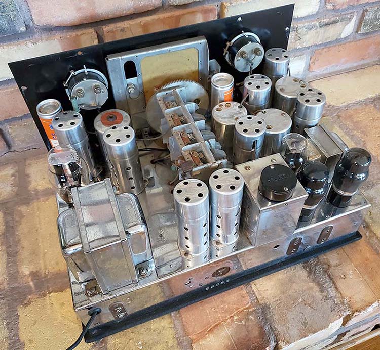
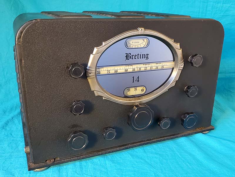
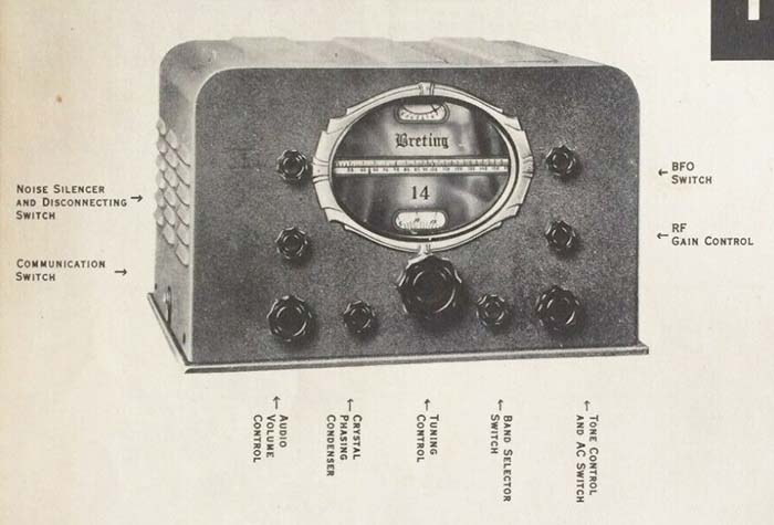
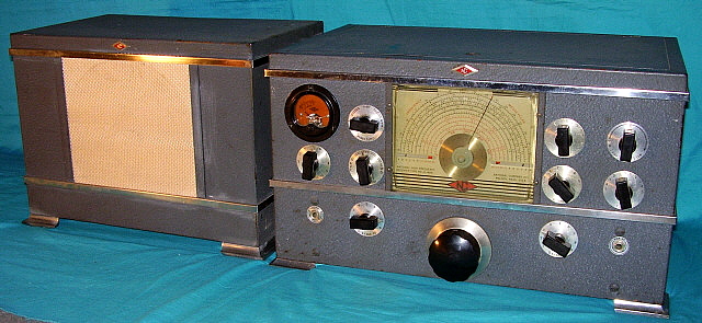
Designed by Ray Gudie, the Breting 14 circuit is almost identical to its predecessor, the Breting 12. The "14" sold for just over $100 and that price also included a chrome-plated chassis with P/P audio using a triode-connected 6F6 driver and triode-connected Push-Pull 6F6 output tubes. The magnificent mirrored dial inside an almost Art Nouveau style bezel also featured an edge-lighted translucent plastic tubular rotating dial-drum scale for band-in-use readout and a red translucent pointer is backlit onto the logging scale (the same style bezel though slightly smaller was used by Patterson for their PR-15 receiver.) The "R" meter also had an edge-illuminated translucent scale. Certainly the dazzling dial illumination during operation gave the Breting 14 an impressive bench presence that hopefully made up for some of its design idiosyncrasies. However, that fabulous front panel infatuation soon vanished when the owner needed access to the chassis for routine tube testing or minor adjustments. The cabinet has no lid and requires complete removal for any sort of "top of the chassis" checking. The cabinet is only mounted with four large thumbscrews but a lid still would have been more convenient. The bottom cover is attached by way of the metal glides that when threaded into the chassis mounting brackets not only hold the bottom cover in place but also act as feet. Tuning Dial Vernier Variations - The original bandspread was mechanical and was a vernier mechanism that allowed several turns of the main dial in slow-motion and then, if tuning in the same direction continued, a direct drive type of fast tuning engaged allowing quick placement of the tuning condenser to the desired location. If the direction of tuning was reversed, then the "slow-motion" re-engaged for several turns again and then the fast tuning again engaged. This allowed all fine tuning to be accomplished with just one dial. On the receiver shown in the photos, SN:49555, the vernier tuning control is accomplished using the knob on the lower right side of the panel. The vernier action is by a tuning belt that runs from a large pulley on the tuning condenser shaft mounted just behind the logging dial to a very small diameter pulley on the vernier shaft. The belt is a type of small diameter, tightly coiled spring that is very flexible and able to provide its own tension. This vernier control is obviously very different in design and also "Rube Goldberg" in its crude implementation. The construction of the vernier drive appears to be original due to the way the pulley is mounted to and as an integral part of the logging dial. The construction of the small vernier shaft while crude appears original. The small pulley is actually made from a plaskon control knob that has a groove machined into its perimeter. The operation of the spring belt was somewhat noisy. The entire vernier mechanism design and construction looks like a prototype and not something that would found in a production receiver. Other changes in this receiver are that the RF Gain control occupies the BFO switch location and, as mentioned, both of the BFO controls are located underneath the cabinet and original holes in the bottom plate indicate these locations are original to this receiver. The original artwork shown RF Gain control position is occupied by the Tone-AC switch in SN:49555. All of the wiring looks original and has the "patina of age" appearance. The mechanical differences look original albeit crude in workmanship. Breting 14 AX and Another Vernier Tuning Variation - In 1938, a circuit change in the Noise Silencer prompted a designation change to "Breting 14 AX" but the documentation for this change was never published. The common belief was that the 6H6 duplex diode was changed to 6C5 triode however the circuit modification was much more elaborate and actually used the 6C5 as the R-meter amplifier (how the BFO tube could double as the R-meter amplifier was a mystery when examining the schematic.) Additionally, the last IF amplifier tube was changed from a 6L7 to a 6K7 and Crystal Filter modified so that the 432kc crystal could be mounted under the chassis. The mirrored dial was changed to "14 AX." The vernier tuning was also changed. As mentioned above, the first vernier was a dual-speed mechanism on the main tuning shaft. SN:49555 has the lower right-most knob and a belt system. There was another vernier version on the 14 AX that used a rubber drive wheel and utilized the knob that had been for the Crystal Filter (which, of course, was also then relocated to the lower left-most control.) Lack of any Breting detailed documentation or documentation of any upgrades is a problem common to the all subcontractors that were building their radio receivers at Gilfillan. It's also quite likely that Breting offered the "14" in a floor console cabinet as he had with the "12." Very few built and there are few-to-no survivors. Also, some 14 AX versions show up with gray cabinets. Some may even have silk-screened control nomenclature.
|
|
|
Utah Radio Products Company - UAT-1 "Add-A-Unit" Amateur 80 Watt Transmitter Kit Utah Radio Products sold many different types of radio components from the 1920s up into the 1950s. Although mainly known for loudspeakers in the 1920, Utah also produced various type of transformers and chokes along with many other radio components. In 1937, Utah introduced the "Add-A-Unit" series of transmitter kits. There were five different kits that could be purchased with the designation being "Kit No.1," "Kit No. 2," etc., up to "Kit No. 5." Kit No. 1 was an 80 Watt input power transmitter that used a metal 6L6 crystal controlled oscillator and two parallel connected metal 6L6 tubes as the PA. Plug-in coils had to be wound as part of the kit construction with plans for coil sets covering 160M, 80M, 40M and 20M. Additionally, Utah would supply construction details on 10M coils on request. Three coils comprise each set with an oscillator coil, a PA input coil and a PA output coil. Four pin Hammarlund forms are used for the oscillator and PA input coils and a Hammarlund large five pin coil is used for the PA output coil. The PA output is link-coupled to either an antenna that is cut for a specific operating frequency or to an antenna matching device. Power supply is built-in and uses all Utah "iron." Price was $49.75 Kit No. 2 was a 50 Watt Modulator priced at $44.50. Kit No.3 was the Antenna Coupler priced at $13.95. Kit No. 4 was a 500 Watt input RF amplifier priced at $49.75. Kit No. 5 was a 250 Watt Class B Modulator priced at $49.75. When all five kits were assembled together, the builder ended up with a 500 Watt AM-CW transmitter. The idea of "Add-A-Unit" was driven by the Depression and the fact that most hams didn't have the money to purchase all of the kits simultaneously. A prospective builder could start with Kit 1 and probably Kit 3, which would result in an 80 Watt CW crystal-controlled transmitter that could be matched to several types of antennae. Later, Kit 2 could be added for AM operation. Then perhaps last, Kit 4 and Kit 5 could be added giving the builder a complete 500 Watt AM-CW transmitter with the purchase spread out over the time necessary. Shown to the left is the UAT-1 80 Watt transmitter and a copy of Kit 3 Antenna Coupler. The coupler requires balanced feed line going to a dipole antenna. I usually can get about .6amps of RF antenna current. I had a two-way QSO with K7RLD (Washington state) with this set-up. K7RLD was using his Utah UAT-1 transmitter. Probably the first two-way UAT-1 QSO in several decades. |
|
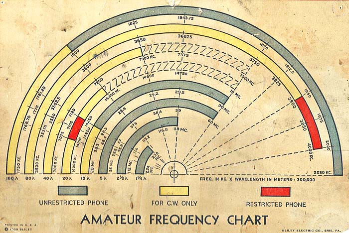
Bliley
Electric Company Did you ever wonder what the granted ham frequencies were before WWII? Shown to the right is a 1939 multi-color chart put out by Bliley Electric Company, the famous quartz crystal manufacturer. 160M band shows 1750kc up to 2050kc. It was the popular Phone band because it could be used by newly licensed hams (Class B.) 50kc was CW only. The 1936 ARRL HB shows the lower end of 160M was 1715kc at that time. 80M was the same frequencies as today but was CW only except for 100kc Phone for Class A licenses. 40M was the same frequencies as today but was totally CW only. 20M covers 14.0mc up to 14.4mc and only had a small 100kc section for Class A Phone. The remaining 300kc was CW only. 10M was from 28.0mc up to 30mc and allowed Class B licenses to operate Phone from 28.5mc up to 30mc. 500kc was CW only. "Restricted Phone" indicates Class A license. "Unrestricted Phone" was for Class A or Class B licensees. Class A required one year experience and a more difficult test. Class B required no experience and a less difficult test. Class A, B or C had a 10wpm code test requirement. Class C license was the same privileges as Class B but testing was administered by mail and volunteer examiner. |
|
|
|
||
|
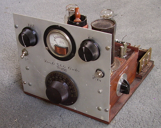
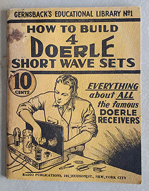
Doerle Globe Circler In the 1930s, Walter C. Doerle of Oakland, California, came up with several types of regenerative detector receivers for the "homebrewer." Hugo Gernsback published a book (in 1935) that was titled "How to Build Four Doerle Short Wave Receivers" and it became a very popular publication. In fact, the Doerle-circuit receivers became so popular with "homebrewers" that some builders started "Doerle Receiver" clubs. The receivers generally were a regenerative detector in combination with a single stage of audio amplification. The antenna was capacitively coupled to the plug-in coil so no primary winding was used on the single RF coil but a tickler coil winding was used. Usually, type-30 tubes were specified but 201A tubes or 99 tubes were also sometimes used by builders (although they didn't have the gain that type-30 tubes did.) To keep costs down, the Doerle receivers were almost always battery-operated. Audio reproduction was for a Hi-Z headset. Doerle did come up with many improvements to the design by adding a RF amplifier and AC power supply as part of the plans. Like any homebrew or kit, Doerle receivers are unpredictable as performers. Most homebrew builders weren't radio engineers or technicians. They weren't experienced assemblers like those that worked in radio factories so many homebrewers lacked the basics in good soldering ability. Most homebrew builders during the Depression didn't have any test equipment. Careful winding of the coils required experience and well-made coils helped to provide the best performance from the simple Doerle circuit. Doerle himself states that the coil wire, the coil forms and careful winding were necessary for top performance from the receiver. Since many homebrewers lacked basic electronic skills, very few adhered to layouts or even read the instructions or understood the information provided. So, most of the Doerle receivers will have a variety of problems from wiring lead dress and component placement to fundamental wiring errors. Plus, since the receivers were usually built during the Depression, used parts and sometimes wrong component values were used since the builder probably couldn't afford anything else.
Many radio enthusiasts still build Doerle regenerative receivers. Some builders prefer to use mostly vintage parts while others, trying to get "the most" out of the circuit, use modern equivalents. There's ample info on the circuits and performance reviews on the Internet. Typical of 1930s radio write-ups, don't expect a lot of theory or details on circuit function from the Doerle book (yes, I've read it.) It's written in the vernacular of the radioman of the time and is humorous in its style. It's a little short on theory but there's enough building data for a homebrewer to complete a receiver that would function as described. Doerle probably didn't know much more than the average well-experienced ham of the day when it came to the theory of receiver design but he did know "receiver construction" and how to get the most out of a simple, two-tube receiver. NOTE: Where the heck did I find this Doerle Globe Circler? Of all places, right here in Dayton, Nevada. Around 2015, there was a massive "yard sale" here in Dayton. But, it was so massive it was being held in a vacant field a mile or so away from my QTH. There was an incredible amount of "stuff" just laying around in the field. From barbeques to horse saddles, old barely-running cars to house electrical and plumbing items. But, there were a lot, and I mean a LOT, of vintage electronics and ham gear also laying around in the field. I talked to the guy running the "sale" and he said all of the electronics had come out of a house and garage in Silver City, Nevada (halfway between Dayton and Virginia City.) There were several pretty nice ham-related items including a few boatanchor receivers and a lot of test gear. A real surprise was this Doerle receiver in amongst the junk parts. Price? $5.00. |
|
The Hallicrafters, Inc. SX-11 The SX-11 was a major step forward for Hallicrafters. As a continuation of the design and manufacturing style that was used with contactors, Hallicrafters' engineers designed the SX-11 to be built from purchased parts that could be assembled into a first-rate communications receiver. The SX-10 and SX-11 were the first receivers that Hallicrafters built without the use of contractors. The SX-11 boasts several firsts for the company. It was Hallicrafters' first receiver with Push-Pull audio output, first with a tuning-eye tube, first to use a separate speaker. The 11 tube superheterodyne circuit also has such unusual features as variable injection BFO, 0-200 bandspread scaling, illuminated main dial, 6L6 tubes in the P/P audio output (14 Watts of audio) plus the fabulous styling that remained in the Hallicrafters line for the next several years. The SX-11 evolved during production with early versions sporting SX-9 type knobs and several circuit differences from the later versions. From the factory, the SX-11 was housed in a metal enclosure painted black wrinkle but the advertised SX-11 was also sometimes pictured in an after-market, shielded (copper sheeting on the inner surfaces,) solid-walnut cabinet. These wooden cabinets were not a Hallicrafters' product but were available from various "jobbers" during the thirties and the cabinet dimensions allowed the installation of several other makes and models of receivers. |
|
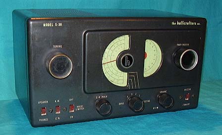 The original 1946 Hallicrafters S-38 used six tubes, had a real BFO and had a Noise Limiter circuit. |
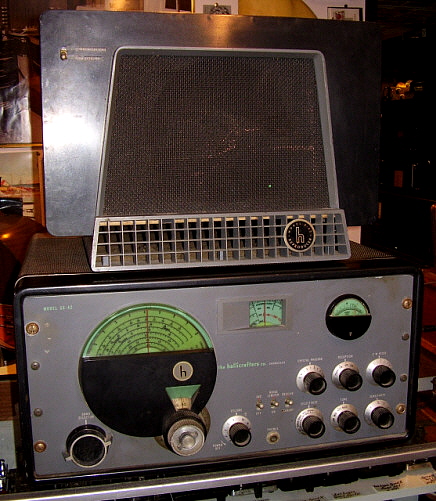
the Hallicrafters, Inc. - S-38 Series The S-38 was a post-war continuation of the "introductory" type receiver line, characterized by the pre-war Sky Buddy series. Intended to introduce young radio enthusiasts the shortwave broadcast reception, the S-38 was low-priced, easy to operate and most users were able to get decent performance results considering the receiver's obvious circuit limitations. Introduced in 1946, the initial S-38 had six tubes with Bandspread, BFO and Noise Limiter circuits. All of the S-38 series receivers were AC-DC operated. Shortly after its introduction, the circuit was changed to a five tube set with no noise limiter and a CW position that used a gimmick to actually set-up a regenerative oscillation in the IF. There certainly must have been complaints about the performance of these later S-38s since CW is next to impossible to receive with the IF amplifier in oscillation. The gimmick used was a length of wire under the chassis that is moved around until the regenerative oscillation seems like it might allow CW copy. Needless to say, most youngsters were listening to SW BC and hams on AM phone anyway (unless they really wanted to become hams - then good CW performance was important.) S-38 versions A, B and C have semi-circular dials while the D and E versions have slide-rule dials. Selling price was around $40 in 1946 but by production's end, in 1961, the price had climbed to $55. The first version cabinet was designed by Raymond Loewy, though Loewy actually won an award for the SX-42 cabinet design. Also available were two custom finish S-38E models. These were the S-38EB, a blonde faux finish version and the S-38EM, a faux mahogany finish version (shown to the right.) |
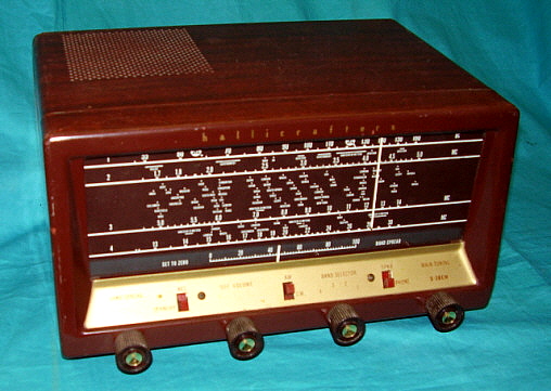 The faux mahogany finish of the S-38EM |
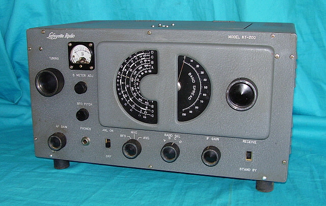 |
Lafayette - KT-200 - aka: Trio HE-10 or "S-38 Look Alike"
In 1959, Lafayette began selling a receiver kit that was designed and produced by Trio of Japan (later to become Kenwood.) The KT-200 was essentially the Trio HE-10 in "kit form." When assembled, the new owner had a receiver that was capable of "on the air" communications. With a tuned RF stage and two stages of IF amplification along with bandspread tuning, an S-meter and an AC operated power supply, the KT-200 was pretty much a standard "ham receiver." The superheterodyne circuit used nine tubes and was "miles ahead" of the S-38 in performance. The KT-200 also had a real BFO and could copy CW without too many headaches. The receiver front-end and IF transformers came "pre-aligned" to ease assembly and final testing. As would be expected, dial accuracy was vague at best. For about $70 and a few hours of assembly and final testing, the new KT-200 owner had a receiver that looked like a Raymond Loewy creation (actually like a S-38 on steroids) and performed well-enough to actually use "on the air." Whether the operator was a Novice ham and or a frugal but experienced ham, the KT-200 could provide decent reception. Some users would add a Q-multiplier to help with selectivity. There was also a matching loudspeaker available. The KT-200 was available from 1959 up to about 1964. |
|
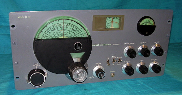
the Hallicrafters, Inc. - SX-42 The SX-42 was introduced in mid-1946 as the post-war successor to the company's former "flagship" - the SX-28A. The SX-42 was a complete departure from the usual receiver styling of the time. Well-known industrial designer Raymond Loewy created a receiver exterior that didn't look like any piece of radio gear that had proceeded his futuristic, award-winning design. The main tuning escutcheon with its green tinted plastic and green main tuning dial resembled something from under a then modern jet canopy. A coaxial tuning system allowed the user to "lock" either the main tuning or bandspread tuning depending on which was going to be used. Besides the ultra-modern exterior, the receiver circuit boasted a very wide frequency coverage of .54 to 108MC with the addition of Frequency Modulation capabilities from 27 to 108MC. The receiver used 15 tubes like its predecessor the SX-28A did but a Converter tube is used rather than separate LO and Mixer tubes. Additionally, a VR tube was included along with Limiter and Discriminator tubes for FM. The SX-42 was single-conversion with double pre-selection on all bands (except band 1, AM-BC) using two seven-pin miniature tubes for RF amplifiers (6AG5 tubes.) Four Loktal type tubes were also used in the circuit and the remaining nine tubes were standard Octal types. The audio circuit used P-P 6V6 tubes and provided 500Z ohm and 5000Z ohm outputs. Selling price was $250 but, by 1947, the price increased to $275. There were several matching speakers available but the R-42 table-top bass-reflex speaker is generally pictured with the receiver in Hallicrafters' advertising. Another accessory was a table top "Tilt-Mount" on which the receiver was placed. The Tilt-Mount then allowed the entire receiver position to be moved in any angle to allow a comfortable view the receiver front panel. |
 |
|
|
Early versions of the SX-42 will have a greenish colored bezel on the bandspread dial and a black background "h" emblem on the dial. Later versions have a light gray bezel on the bandspread dial and a silver background "h" emblem. The are a multitude of engineering upgrades to the circuit and manufacturing process all through the SX-42 production. The SX-42 was really never a very popular receiver with hams. Certainly the expense of the receiver was an important issue for many but its unusual looks, which hams may have been considered "too modern" in the then age of "wrinkle finish black panels," may have also been a factor. The coverage of the then new FM band (88 to 108MC started in 1946) may have made hams feel that the receiver was more of an expensive luxury for the well-to-do consumer than for a typical budget-minded ham. At any rate, production of the SX-42 was stopped in early 1948 - a fairly short lifespan for a "flagship" receiver. The SX-62 took the SX-42's place as the high-end Hallicrafters receiver but it seemed to again be more for the consumer market and very few hams bought them as their station receiver. The popular SX-71, certainly designed for hams, filled in that portion of the ham communications receiver market after the demise of the SX-42. Today, the features that resulted in the SX-42's only moderate success are what attract collectors to the receiver - the futuristic styling (which won an International Design Award for Raymond Loewy from the NY Museum of Modern Art,) the wide-swing FM-BC coverage, the fabulous audio (when using the proper Z speaker) and the relative rarity of finding an example in nice cosmetic condition all contribute to the SX-42's desirability. Additionally, the SX-42 is featured in a plethora of late-forties "B" movies, from Gene Autrey to low-budget science fiction movies, early TV shows like Sky King, meaning that SX-42 fans can regularly spot their favorite receiver in a multitude of film backgrounds. Shown in the photo to the left is a later version of the SX-42 along with the matching R-42 bass reflex speaker. This combination was purchased for K6HUZ by his father as a special gift for passing the General Class license exam. It was 1954 and the SX-42 and R-42 were found in a pawn shop not far from the Federal Building, where the FCC administered the amateur exams, in downtown Los Angeles. K6HUZ kept the receiver and speaker in great condition for 57 years, then donating it to our museum. The photo above in the header shows an earlier version of the SX-42. I found this receiver in a backyard shed in Gardnerville, Nevada. It had been the victim of poor troubleshooting and had several modifications to the circuit trying to correct a fundamental mis-wire that happened when the filter capacitors were replaced. I had to strip out the IF section of the receiver and rebuild it to stock. I went ahead and fully re-capped the receiver. It now works fabulously with great audio and respectable sensitivity. I have yet to have the "gun metal dark gray" paint matched so I can restore the cabinet on this early version SX-42 |
|
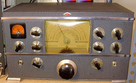
National Company, Inc. - NC-240D (aka: NC-2-40D) National's "Moving Coil" receivers utilized a cast-metal catacomb that carried the various front-end coils and placed them into contact with the tuning condenser by way of small contact pins and pin-receiving contacts. The catacomb was rack and pinion driven with a large knob on the front of the receiver. The initial "Moving Coil" receiver was the 1936 NC-100. In 1940, the NC-200 was introduced and it featured both general coverage coils and amateur band spreading coils. During WWII, National produced the NC-200 receiver for various uses. However, like most military receivers, the amateur band spread function was eliminated. These receivers were designated as the NC-240CS. Immediately after the war ended, National did sell some NC-240CS receivers to the civilian market but most were considered "commercial" receivers. The NC-240CS was also used as an Airways Receiver designated the RCR. In a short time, National reinstalled the amateur band spread and designated the new receiver the NC-240D although some ads and a few manuals show the model as NC-2-40D (this was probably a literal representation of vocally how the model was referred to,..."NC two-forty D.") The NC-240D added metal pedestal feet to the receiver cabinet. The single large knob that provided tuning when pushed in and changed bands when pulled out was unchanged from earlier versions of the NC-200 series. Initially, the NC-240D was supplied with the round flange Marion Electric S-meter, which was the same S-meter used in many pre-war National receivers including the HRO Senior. By 1947, the round flange meter was replaced with a square flange S-meter, also from Marion Electric. |
|
|
Note in the photo above-right, the NC-240D dial has all of the Band Spread scales near the center of the circular arc of the dial. Later NC-240D dials will have the Band Spread scales directly above the A, B, C and D General Coverage bands (see lower photo.) Production of the NC-240D continued through most of 1948. The NC-240D was the last of the "Moving Coil" receivers produced by National - a design that was produced from 1936 up through 1948 and included the famous WWII Navy RAO line of receivers. |
||
|
|
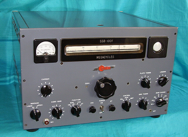
Eldico Electronics - SSB-100-F
Eldico is mainly known for the Collins S-line "clones" they built around 1960. These initially were part of a military second-source contract between Eldico and the Air Force, however Eldico then decided to also sell the "clones" directly to the general public. That Eldico was using the S-line clones to apparently compete with Collins upset that company, who then pressured Eldico to stop production of the clones. However many examples were sold and they are still relatively easy to find. Supposedly, the designer of the Collins 75S-3 was also the designer of the Eldico R-104 (urban legend?) The SSB-100-F came out in 1957. It was a balanced modulator-crystal filter ssb supression type transmitter that used 5894 in the final PA. The transmitter covered 80M thru 10M with 10M covered in three individual bands. 11M was also covered since the SSB-100-F was a pre-CB era rig. The circuit uses 22 tubes including a 1CP1 1" diameter CRT that is used to provide a trapezoid pattern for monitoring transmitted audio quality. The SSB-100F was rated at 100 watts PEP input power in SSB, 50 watts input power on CW and 25 watts SSB-AM. Only one sideband could be transmitted in the AM mode. Carrier was reinserted post-filter to accomplish a SSB-AM signal. VOX or Manual operation was provided but not PTT. Not too many SSB-100-F were produced. Priced at $795, it's not surprising that sales were slow. Estimates are around 300 to 500 units were produced, which is probably too high for the actual production based on how few SSB-100Fs are found nowadays. The SSB-100-F shown is serial number 0067. I also have a "parts set" SSB-100F with the serial number 0079. Eldico also produced a SSB-100MIL version that provided 12 crystal-controlled selectable channels besides a VFO. Eldico also produced a linear amplifier, the SSB-1000. |
|
 |
DCS-500 - Homebrew Double-Conversion Superhet Receiver From the 1962 Handbook up to the 1964 Handbook, the "top of the line" homebrew receiver project was the "DCS-500." This was a formidable project for the homebrewer consisting of a 12 tube plus two transistor, double conversion superhet that had an impressive layout and appearance that was sure to also have a dominating bench presence if the project was successfully completed. The receiver used plug-in coils to eliminate complicated bandswitching and reduce losses that might otherwise be encountered with having all of the coils present under the chassis. The plug-in coil design simplified a portion of what was already a fairly complex receiver. The first conversion was at a fairly high frequency of 4500kc while the second conversion was very low at 50kc. The very low 50kc IF was popular in the 1960s as it provided excellent selectivity. J.W. Miller TV coils were slightly modified and used for the IF transformers and BFO. The 4500kc IF had its bandwidth determined by a four crystal IF filter that utilized surplus FT-243 crystals. The second conversion oscillator also used a surplus FT-243 crystal operating at 4495kc. Four positions of selectivity were part of the circuit with the bandwidth determined by fixed capacitors. The detector was a standard envelope (diode) detector but the BFO injection was robust so SSB signals could be demodulated easily. AGC, Noise Limiter, BFO, Crystal Calibrator (where the two transistors were used) Antenna Trimmer and a S-meter were all features of the DCS-500. Audio output was either a headset using the phones jack on the front panel or 3.2Z ohm loudspeaker using terminals on the rear chassis. Other features available on the rear of the chassis were remote standby, 50kc IF output, accessory B+ output and the 3.2Z ohm speaker terminals. The project in the Handbook shows the receiver built with many National Company parts, J.W. Miller coils and a large Bud Industries cabinet. The build-concept was to use easy-to-obtain parts (at the time they were easy to obtain,...not now.) Almost everything could be ordered from any of the large catalog suppliers like Allied, B-A or Lafayette. This DCS-500 was constructed using almost all of the recommended manufacturer parts and therefore is very close in appearance to the project receiver shown in the ARRL HB. |
Most likely, if the DCS-500 was going to be constructed, the homebrewer probably was experienced in electronic construction techniques and probably was a competent sheet metal worker. Many electronic "kits" or less complicated homebrew projects were often built by beginners with no electronic assembly experience. A close inspection of the soldering quality is generally a clue that indicates the level of experience of the builder. Overall this DCS-500 receiver looked like a very talented and experienced builder had performed the construction. However, appearance and functionality don't necessarily relate to each other. As found, this DCS-500 was non-functional. It was in very good cosmetic condition although very dirty and obviously contaminated with some kind of white residue that adhered to mostly the plastic items. I didn't have the correct year ARRL HB, so my first task was to find a 1963 HB (and that was easily and quickly found on eBay.) I decided to go ahead and do the preliminaries before any documentation arrived. One shorted 6U8A tube was found with all other tubes checking out in good condition. The power supply filter capacitor was reformed but, although not shorted, it didn't filter very well either. A couple of "piggy-backed" electrolytics got the hum down enough to proceed. Starting at the audio circuitry, I had output with a 400hz signal injected to the grid of the 6AQ5. I injected a modulated 50kc signal at the grids of the IF amplifier tubes and also had audio through to the speaker. Injecting a 4500kc signal into the Mixer stage also produced a speaker response but nothing could be heard with the signal generator connected to the antenna. Further testing showed that the first conversion oscillator wasn't functional. I checked the oscillator plug-in coil and noticed that the trimmer capacitor (air variable) was shorted. The type of trimmer used the hex collar to secure the rotor shaft. The hex collar had come loose and dropped the rotor and that was shorting the trimmer. I repaired the hex collar (sweat soldered the hex collar in position) and now the oscillator seemed to be somewhat functional. There now was "tunable" noise although not anything like 40M signals. At this point, my 1963 HB was going to be delivered the next day, so I stopped troubleshooting since more information in the form of the schematic and the HB write-up would be immensely helpful. By this time, I had discovered that the Crystal Calibrator had never been functional since there was no connection to the chassis. I had also discovered two unsoldered joints, one on the first conversion oscillator coil pin and one on the antenna coil pin. Although the soldering looked fine as far as quality, more problems were discovered as troubleshooting proceeded. It was beginning to look like this DCS-500 was never totally completed and, positively, it was never functional. The lack of any dial frequency nomenclature was one clue that no calibration took place. The lack of a chassis connection for the 100kc calibration oscillator was another indication. Once I got the receiver somewhat functional, I found that it had never been aligned. The 50kc IF was resonate at around 55kc which was probably where the slugs were set from J.W.Miller. The S-meter was wired backwards. The Audio Gain control didn't have a connection to chassis and ran "full on" until corrected. Although the dial tuning was loaded with "birdies" it did tune in a couple of SW BC stations - only they were around 9.3mc rather than 7.3mc. This problem was caused by the LO coil being wired incorrectly inside the coil form. The non-functional BFO was caused by the BFO coil being wired with the grid side being connected to the rotor of the BFO tuning condenser that was also physically connected to chassis. Rewiring the tuning condenser corrected the problem and got the BFO working. The second 4500kc IF coil (L5) wouldn't adjust. This problem was caused by a "never installed" wire that connected the B+ side of L5 to the crystals. Noisy operation of the 4500kc IF was caused by an unsoldered bypass capacitor. Finding each of these problems resulted in the DCS-500 working better and better with many 40M signals now being received. This DCS-500 only had one set of coils with it,...the ones that were installed. They were for 40M. Tracking is set at the high end of the band with the LO and Mixer trimmers. The low end "spread" is set by "pushing turns" on the coils. Each set of coils would be different and dependent on how the coil was wound by the builder. I had to "push" the LO winds closer together to get the 40M band to track from 7.0mc = 10 on the dial to 7.3mc = 90 on the dial. This allows a little tuning above and below the ham band for checking other types of signals. I checked my junk boxes and found two blank polystyrene coil forms, a four pin and a five pin. I needed one more five pin. A short while later, I found a couple of 80M coils for the DCS-500 at "Ham & Hi Fi" in Sparks, Nevada. I still have to wind the Antenna coil for 80M. If more of the clear polystyrene coil forms are found, I would then next wind a set for 20M. When I have the 40M and the 80M coil sets complete, I'll add calibration to the National tuning dial. Improvements to the DCS-500 could be some additional shielding and better filtering on the power supply. A bottom cover would probably help a lot. If the receiver is installed in a cabinet then the chassis should be bolted to the cabinet so that it provides the bottom shielding. An extra filter choke and filter capacitor would be a big help for the hum level which is fairly high if the receiver is operated with the AVC off, AF gain high and riding the RF gain for best SSB and CW reception. This set-up does result in noticeable hum. The DCS-500 can be operated with the AVC on when in CW or SSB, but, receiving in poor conditions is improved with the manual gain set up with AVC off. The HB article recommended an angle aluminum extrusion be mounted to the top of the chassis to "stiffen" it. This particular DCS-500 doesn't have that installed but I think it would help to improve stability if it were installed. |
|
|
Radio Boulevard
Western Historic Radio Museum
Vintage Radio Communication Equipment Rebuilding & Restoration Articles,
Vintage Radio History and WHRM Radio Photo Galleries
1909 - 1969
- 60 years of Radio Technology -
This website created and maintained by: Henry Rogers - Radio Boulevard, Western Historic Radio Museum © 1997/2025
