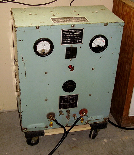
| PP-1104 Operation -
Using the PP-1104 to operate dynamotors eliminates most of the headaches
since the power supply is capable of providing the required starting
current without hesitation. Also, since the PP-1104-C can be adjusted to
over 40vdc output voltage, adjusting to 28vdc under load is easy and
allows the BC-375 (or any other DC operated military transmitter) to run
efficiently and with maximum RF output power (around 75 watts output
typically for the BC-375.) The usual load at +28.5vdc input for a BC-375
is about 8 amps in standby and about 25 amps during transmit. The BC-348
receiver will add another 2 amps making the total current draw for the
BC-375 and BC-348 about 27 amps with some increases in current demand
with voice peaks. Be aware the the "instantaneous starting current" on any dynamotor
is much higher than the "at speed" current. Typically the BC-375 will
"peg" the current meter for an instant as the dynamotor begins to
rotate (but the accuracy of this measurement is unknown but it an
estimate is probably 60 amps minimum.) As soon as rotation begins the
current requirement drops rapidly and the dynamotor attains full RPM in
less than half a second. Most power supplies will have two ratings, one
is continuous current and one is "peak" current specified for a limited
time period. Linear power supplies generally can supply "peak" current
for a longer period of time than switching power supplies but as
switching power supply technology improves, the "peak" current time
durations are increasing with some switchers able to provide peak
current for 10 seconds or more, which is much longer than the dynamotor
needs to come up to speed. Another PP-1104-C Suggestion
- In looking at the photo of my PP-1104-C above you will probably see
that I have it setting on a small furniture dolly. I bought the small
dolly at Harbor Freight Tools but I think they are available at almost
any large hardware or tool store. The small dolly is a perfect fit for
the PP-1104 and allows it to be moved around the shop with ease.
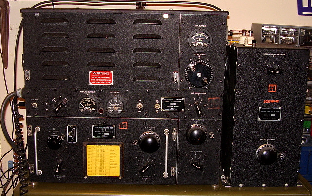
IMPORTANT - The PP-1104-C Needs to be Operated on
240vac -
The PP-1104-C operates much more efficiently when powered by a
230-240vac line voltage. These power supplies were originally delivered
set-up for 230vac operation. The cover on the right side of the cabinet
can be taken off to reveal TB1 terminal strip and if terminals 2 and 3
are jumped, the input voltage should be 230vac. If terminals 1 and 2 are
jumped and terminals 3 and 4 are jumped, the input voltage should be
115vac. AC line input is on terminals 1 and 4 (and 4 is jumped to 5 at
all times.) The momentary output voltage drop when a large load is
switched on is greatly reduced when the PP-1104-C is operated on 230vac.
However, the PP-1104-C does operate okay, in most cases, on 115vac.
I've been running the Gladding-Keystone on 120vac for over ten years and
only twice have I had problems but both problems were related. In one case
had a problem running a DY-12 dynamotor. Although that dynamotor ran
fine once up to speed, on many occasions the
PP-1104C output voltage dropped so low with the dynamotor's
instantaneous starting current demand that the dynamotor's start-relay would
"chatter" a few times before the motor started to move and the current
demand dropped. The second problem affected the R-648 receiver that was
also being powered by the same PP-1104-C simultaneously. The "chatter"
of the dynamotor load and the spiking of the PP-1104-C output because of
the rapid load changes, blew the motor winding on the dynamotor of the
R-648. From then on I never operated any equipment in parallel with the
PP-1104-C. The R-648 needed a new dynamotor for the repair. A test of
the "problem" DY-12 operating on a second PP-1104-C
running on 240vac didn't produce any "chattering" when powering up an
ART-13 transmitter. I now operate all of my PP-1104-C power supplies on
240vac.
|
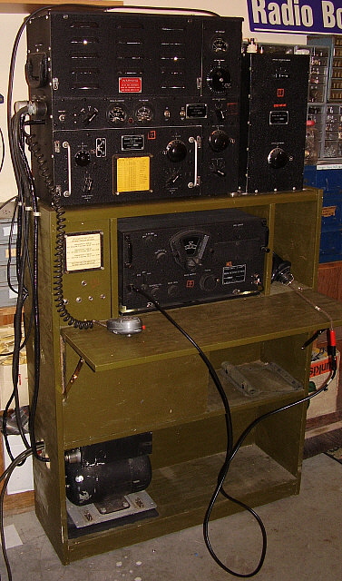
Eliminating the
PP-1104-C
No doubt, a PP-1104-C will take up a lot of space. It's a very
heavy power supply that's about the size of a large, stand-up laundry
hamper that weighs 100 pounds! Finding a good one that operates quietly
is difficult and most PP-1104-Cs are usually fairly expensive. Shipping
a PP-1104-C requires the seller to be willing to prepare a 100 pound
device for safe shipping, usually by freight. Then, when you have a
PP-1104-C, it will only operate correctly and to spec when running on
240vac. A lot of headaches.
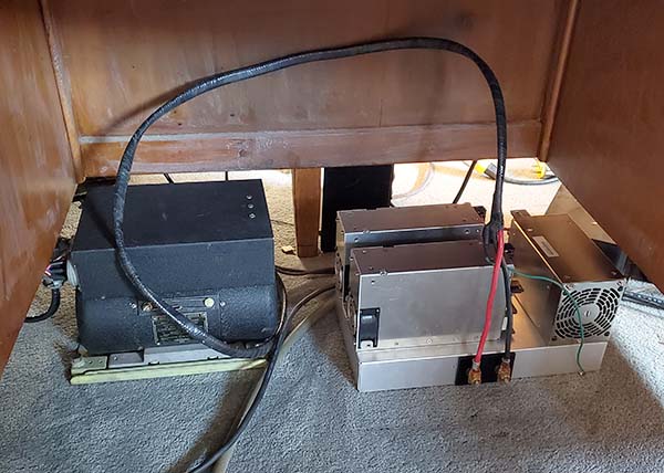
Recently (2024), I rebuilt a USN ATD Aircraft
Transmitter that I wanted to operate upstairs using its original ATD
dynamotor. This required +28vdc with a minimum of about 60 amps
for the instantaneous starting current. Moving one of the
PP-1104-C power supplies upstairs was "out of the question," so
I had to come up with a "light-weight" method to supply +28vdc
at a minimum of 60 amps. I used three 24vdc 27 amp Lambda
"CE-rated" switching power supplies connected in parallel. If
adjusted accurately to exactly the same voltage from each power
supply, the entire power supply will have the current
availability that's the sum of the current availability from
each power supply. In this case, 81 amps, with a peak current
availability of 93 amps! The best part is
that this power supply only weighs 15 pounds and is built on a 14" x
9"
x 2" aluminum chassis. Because of the CE rating and my use
of grounding with shielded
cables, the "switchers" don't create any RFI.
The best part is that this power supply runs on 120vac with no
problems.
The following write-up is detailing the +28vdc 80amp power
supply (80A-PS) experiments
and building the supply. It references the USN ATD Aircraft
Transmitter but this same 80A-PS can power any +28vdc dynamotor
with ease. There is a difference between the ATD dynamotor and
the BC-375 dynamotor. The ATD is a dual voltage output while the
BC-375 dynamotor only produces +1000vdc output. The "motor side"
of both dynamotors have the same type of high-current demand
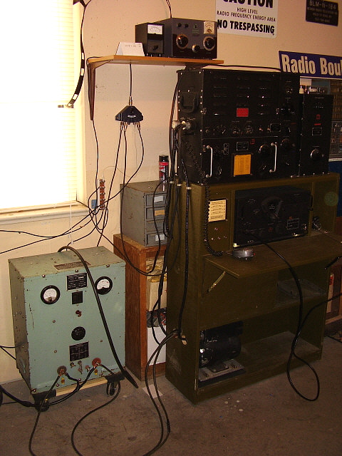
requirements. Shown in the photo to the right is the 80A-PS
located under the operating desk in the foot well area. Note that the
power supply is about the same size as the ATD dynamotor. |
 |
| My first tests involved using some spare 24 volt
Meanwell switchers I had,...
A Tiny Power Supply for Dynamotor
Operation - To power up the ATD dynamotor requires at least
45 amps of starting current. I tried 40 amps and the dynamotor pulses,
the relay chatters and the armature slowly rolls but never increases
speed. At 53 amps the dynamotor starts right up and gets to full speed
in about a half-second. Actually, these switchers will supply even more
current "peak" for about ten seconds which is more than enough time to
start up the dynamotor. The "peak" current available is about 65 amps. I
used an old ART-13 dynamotor battery cable that I modified by reworking
the connector. The ART-13 dynamotor uses pin 2 for +28vdc input while
the ATD dynamotor uses pin 3 for the +28vdc input. I had to simulate the ATD PTT that "turns on" the dynamotor. For
this I used two test leads,...one for +28vdc going to pin 1 and then
ground going to pin 4. This connection actuates the dynamotor relay and
starts the unit. I measured the voltage output with no load and had
about +1050vdc on pin 8 and about +405vdc on pin 5 (as mentioned above,
the ATD dynamotor is a dual output voltage unit.)
The test setup is shown to the right. I found the two spare Meanwell 24vdc 13A
power supplies out in the shop. They're connected in parallel using 16
gauge wire to
provide 26 amps. The Lambda PS is to the far right and it's connected
in parallel to the Meanwell combo. The Lambda provides 27 amps. I had
purchased the 27A Lambda for an ART-13 power supply that I never built. All
three supplies were set to +27.02vdc (this was the highest voltage that
one of the Meanwells would adjust to, so it determined the voltage
setting for the other two supplies.) Most of these types of switching
power supplies that are rated at 24 volts can be easily adjusted to
28volts using the trimmer pot that's provided. The output of the Lambda has the
battery-type cable that has the ATD-Dynamotor connector on the other
end (this cable is also shielded so it doesn't radiate any RFI.) Since the output of the +HV is +1000vdc, I couldn't use the Fluke
DDM, I had to use the Triplett VOM to measure that voltage.
Note,...this is one LOUD
dynamotor (like a big shop-vac) I was worried about the "screaming
fan" on the Lambda PS,...I can't even hear it when the dynamotor is
running. NOTE:
Meanwells are inexpensive switching power supplies that will function
okay for powering dynamotors. I prefer the Lambda type as they have
better adjustability. The 24 volt Lambda units will always adjust up to
28 volts. I use the Meanwells for experimentation projects. |
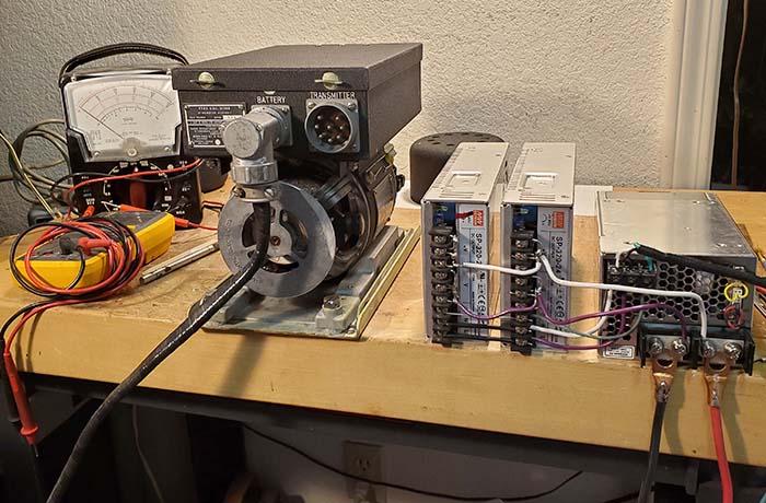
Here's the "test set-up" for the ATD
Dynamotor. The parallel switcher-type power supplies provide 65 amps
peak at +27vdc, more than enough current to handle the "instantaneous
starting" current to get the dynamotor spinning quickly (with "no
load.") |
| Since it seemed that 53 amps was probably about just 5 or 6 amps over
what was necessary just to get the dynamotor to spin with no load, I
wondered how the extra load of supplying the +28vdc necessary to power up the ATD
would affect the dynamotor operation. About 5 amps are required for the
+28vdc on the ATD alone. Each time the PTT is depressed, the dynamotor
would have to "start up" and that brings in the "instantaneous starting"
current issue. It would be nice to have a lot more "head
room" as far as current availability to smooth out the +28vdc
during the PTT actuation. Would it be possible to order two
more 24vdc 27amp Lambda power supplies? Yes, there are many listed on
eBay. Would it be possible to connect three of these type Lambda Power
Supplies in parallel and have the current availability be 81 Amps
continuous and 93 Amps peak? It
seems so. I've ordered the two additional Lambda power supplies and when
they arrive,...more experiments will reveal if operation of the complete ATD-dynamotor
system is possible with these tiny (but noisy) power supplies. In actual
operation, the high current would only be necessary to start the
dynamotor. As soon as the armature begins to rotate, the current demand
rapidly drops off. When running at speed, the maximum current draw is spec'd at
19 amps and that's the total current including the 5 amps of current
that is necessary for the tubes and relays in the ATD. However, the
instantaneous current draw for starting the dynamotor from a "dead stop"
can be quite high and has obviously been demonstrated to be between 45
and 50 amps,...and that's with "no load." So high current availability
is necessary for quick-starting with the PTT actuation and minimal
fluctuation of the +28vdc to the ATD. Construction
of an 80 Amp +28vdc Power Supply That's Physically the Same Size as the Dynamotor
- When the new Lambda power supplies arrived, I discovered that although
they had the same specifications, they were longer in length and not as
wide as the old 27A Lambda. One letter in the Part Number made the difference.
It doesn't matter as long as they all can provide 27A. I tested these new
supplies and they work fine. I had planned on using a
small BUD Industries cabinet that was NOS condition. It measured 12"W x
8"H x 9"D and it had an unused aluminum chassis that fit inside. However, with the different
dimensions of the two new supplies, this BUD cabinet is too small. But,
I have another unused cabinet that measures 8"H x 14"W x 9"D and it also
includes a chassis (the chassis is 14"x 9"x 2".) But, thinking about the power supplies and their
fans and the cooling,...why use a cabinet? The power supplies can just
mount on top of the chassis. I had thought that due to the noise of the
dynamotor and the power supplies, I'd place both units under the desk.
There's plenty of space and lots of air available. The location would have the
direct noise blocked, the cables are long enough, etc., so just a chassis
for the PS
should be easy and will work fine. I plan on using 14 gauge wire for the AC input
connections and 10 gauge for the +27vdc 80A output. As mentioned above,
this high-current is only "momentary" but I want to make sure that the
IR drop is as low as possible and that's achieved with large gauge
wiring. The normal "running" current demand will be about 20A, so I'll
have plenty of "head room" and that should allow AM modulation voice
peaks to not affect the +380vdc very much (or the +1000vdc HV.) |
| I made my own terminal
blocks out of .250" thick delrin. Delrin is a type of nylon that is
very strong and heat resistant. I drilled and tapped holes in one block
for 4-40 brass screws. The holes were countersunk to allow the screw
heads to be flush with the surface when installed. Then a second delrin
block was used for the insulated base mount. This allowed the terminal block to be
bolted to the chassis and the brass screw heads were insulated from the
chassis by the delrin base. The 14 gauge power cord was routed into the
chassis at the side and the Line, Neutral and Ground wires
soldered to the ends of the three brass screws of the terminal
block (the ends were .750" long.) Then three additional 14 gauge
wires were soldered to the Line and the Neutral terminals and
these routed up through chassis holes to the AC input to the
three power supplies. These chassis holes had rubber grommets
installed. |
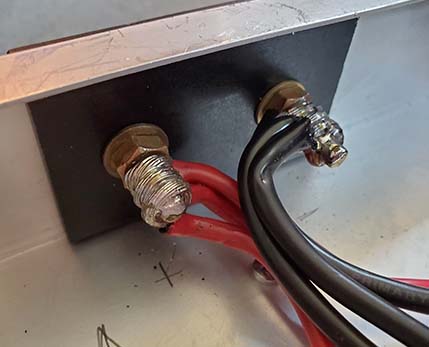
DC Output Terminal Block Inside
Chassis - the studs are 1/4x20 brass and the wires are 10ga. |
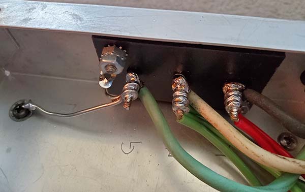
AC Input Terminal Block Inside
Chassis |
| Since the Lambda power supply chassis are all
mounted directly to the aluminum chassis and the Ground terminal on each
Lambda power supply is connected to the power supply chassis, the
individual Ground terminals on each power supply don't have to be routed
to the AC ground wire terminal. But, the AC power cord Ground wire is
connected directly to chassis in two places one of which is a lug under
one of the Lambda power
supplies mounting screws. The AC input to each power supply uses a soldered
ring lug to connect the 14 gauge wires to Line and Neutral. There isn't
a power switch or fuse in the AC input line. The AC line "bounce" is
very noticeable when powering up the dynamotor so a switch and fuse would
just limit the available AC line current somewhat. The 80A PS would only
be plugged in when it's being used. I use a circuit-breaker type power
strip for the AC power.
The DC output of each Lambda was then adjusted to +28.0vdc BEFORE the three
were connected in parallel. I tried to get
the output voltages exactly the same from each supply for equal
distribution of the current carrying ability (within +/- .002vdc.) The DC output terminal block was made from two
pieces of .25" thick delrin with 1/4x20 brass studs and brass nuts and
washers to act as the high current output connections. The clearance holes through
the chassis for the DC terminal block studs were .750" in diameter. The 10 gauge
wires were soldered directly to the back end of the DC output studs. The
power supply end of the 10 gauge wires had ring lugs soldered on and
then these were attached to the PS output terminal strip. The wires were
routed through the chassis by way of grommet-lined holes. With the
completion of the wiring, I connected the ATD dynamotor using the
shielded ATD dynamotor cable. Pin 1 has to connect to +28vdc and pin
4 is connected to ground to energize the dynamotor relay. Start up was
immediate with no hesitation and the armature got up to speed in about 1
second. |
|
Switching noise is always a concern with these types of power supplies.
To keep the RFI as low as possible the AC input and the DC output were
bypassed with .05uf capacitors. The DC cable to the dynamotor is
shielded and the power cable from the dynamotor output to the ATD is
also a shielded cable. Each power supply is in a metal shielded case
that is mounted directly to the PS chassis and the chassis is connected
to the AC house ground. I switched on the Siemens E311 receiver tuned to
3.9mc and using a 50ft wire on the floor as a "noise pick up" antenna.
The power supply noise wasn't noticeable (not above the ambient noise
level.) The starting of the
dynamotor is quite a load, so the receiver reacted to the momentary AC
line bounce but when the dynamotor was up to speed no RFI noise
was heard.
NOTE: As an ultimate
test of this little power supply's current capability, I connected it to
the GRC-19 transmitter-receiver. The GRC-19 is the highest current
demand piece of equipment I have consisting of a T-195 transmitter with
a R-392 receiver operating together. I turned on the GRC-19 and it came
up in Stand By with no problem and no hesitation from the 80A-PS. I
pushed the PTT and the T-195 was putting out 140 watts without any
problem. Modulation was excellent with no change in supply voltage at
all. The 80A-PS powered the GRC-19 just as well as the PP-1104-C does.
No RFI either.
COST: Price on eBay of these Lambda 24vdc 27A power supplies is usually
between $45 up to about $65 each for used, tested good "pulls" plus
shipping - but they're light-weight so shipping isn't too expensive. The
80A-PS cost was about $170 total, although I only had to buy the Lambda
power supplies. The chassis, wire, delrin, hardware and the 14-3 power
cable I salvaged from the junk box. |
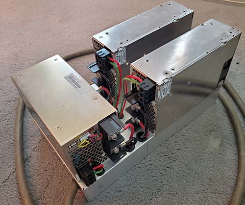
Rear View of 80A-PS showing the
wiring
to the 3 Lambdas |
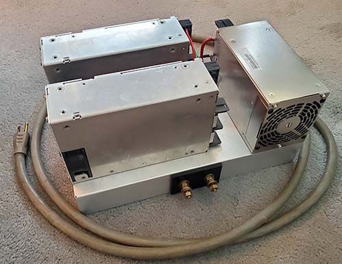
Front View of the 80A-PS showing
the DC Output terminals and Heavy-duty 120VAC power cord (14-3
conductors) |
|
The following,...more than any other factor,...has had a
devastating effect on the future of BC-375/BC-191 preservation,
restoration and operation,...
|
|
The Audiophile (actually, Vacuum
Tube Investor) Market for VT-4/211
Tubes and its Effect on Preserving and Operating BC-375/BC-191
Transmitters
More than anything else, the audiophile/vacuum
tube investor
market for the VT-4/211E tube has made buying or
selling a BC-375 or BC-191 a quandary,...and that's whether the
VT-4 tubes are present or not. If the transmitter is offered for sale without tubes it's
virtually worthless unless the prospective purchaser already has a set
of tubes. If the BC-375 is offered with tubes, then
the purchase price is going to be astronomical. No one would be
interested in the purchase of a BC-375/191 if the "investor price" of the
VT-4s is factored in. And, if the BC-375 is priced less than the going
VT-4 market prices then the purchaser will no doubt be a "tube dealer"
who will pull the VT-4 tubes, sell them on eBay and then "junk" the
transmitter. The last single VT-4 that I saw sell (that was pre-tested and guaranteed) sold
for $500 on eBay. A quad of VT-4 tubes in similar condition would sell
for much more than the four times one would expect. Fair Radio's
2021 price is $250 for known good but not NOS 211-E tubes. Most NOS,
boxed 211E/VT4 tubes sell on eBay (2025) for $1000, incredible but true. The last "tube-less"
BC-375, that I know about, sold for $10 (and that was after the "dealer"
had sold the tubes out of it.) This isn't a brand new situation either
and the escalating prices seem to indicate there's no end to how much
the Hong Kong-based vacuum tube investors will pay for VT-4 tubes. That
leaves the BC-375/191 owner almost afraid to power up his transmitter
for fear he might ruin a tube and then need a replacement. I know one
BC-191 owner that keeps his VT-4s wrapped up in socks and stored in a
safe. The tubes aren't in the transmitter where they should be. It's
possible to slightly modify the BC-375/191 to use the 805 tube,...but,
the audiophile/investors have also discovered the 805 tube, so it's also going
higher in price everyday and they aren't a cheap substitute
anymore. 805 tubes are usually about half the price of the 211.
I'm sure that today the majority of VT-4/211E tubes are NOT being
used. The current audiophile/vacuum tube investor purchasers have no intention of ever
powering up a VT-4. They won't be installing them into any type of audio
amplifier. The only intention is to hoard them for future sale - an
investment. And, because of this hoarding/investment and its effect on
VT-4 prices, today, (2021) it's rare to hear a BC-375 or BC-191 on
the air. I don't know of any that are undergoing restoration.
Most military radio enthusiasts figure "why try to operate a
transmitter that is so expensive to restore and so difficult to get
to sound good when, for a fraction of the cost, an ART-13 can be
purchased and it runs twice the power output - and sounds really good
doing it - and the tubes for it are cheap and of no interest to audiophiles
or investors."
If you're patient, with a little luck in checking swap meets and ham
radio listings, it might be possible to find VT-4/211E tubes
"one-at-a-time" for a more reasonable price. Among most military
enthusiasts the VT-4/211E does sell for much less than eBay prices but
it's still an expensive tube regardless of the source (typical
"mil-collector" price usually runs from $75 to $125 for a known-good tube,
not NOS in original box, but this typical sale would
usually be "in person" and definitely not on the Internet.) The key is patience. It might take quite a while
to find a complete set of tubes at a reasonable price but it is still
possible. Undoubtedly, these reasonably priced tubes will be "used" but
should work fine in the BC-375. UPDATE:
March 8, 2021 - I may have to "take back" what I thought about the value
of a "tube-less" BC-375-E. One just sold on eBay for $405.00.
More information, including a possible source of cheap "new" VT-4/211E
tubes,...read on,... |
|
The End of
Operational BC-375 Transmitters? |
|
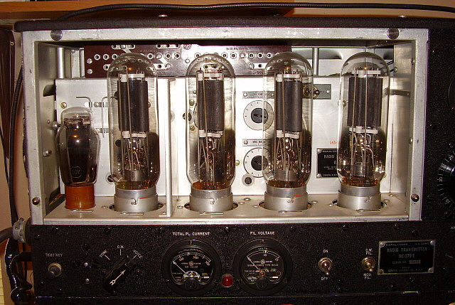
Shown to the right is the interior of the BC-375 showing
the four VT-4/211E tubes along with the 10Y/VT-25 tube to the far left.
The demand by audiophiles (actually by "vacuum tube investors") for the 211E has had a catastrophic effect on
many future restorations or rebuild attempts of the BC-375 transmitters.
It's not at all uncommon for a single 211E in good usable condition to
sell for $250 (that's Fair Radio's 2021 price) and, if the tube is NOS
in the original box, it would sell for double that on eBay (even more
now in 2025.) Power triodes that interest tube investors always sell
for more in a set, so a good condition "quad" of 211E (necessary for a
"tubeless" BC-375) could easily sell for $1200 to $2000. Luckily, these
insane prices are only found on eBay and only when dealing with tube
investors from Asia (or USA sellers that ONLY want to sell to tube
dealer/investors in Asia.) Between military radio enthusiasts a more
common price is about $125 a piece for a good usable 211E but that's
still $500 for a quad if you have a "tubeless" BC-375. The 10Y is
still not expensive (except the Western Electric VT-25 version.)
There is a fairly common VT-4 substitute tube, the 805.
However, although the 805 is an identical tube to the 211E, the external
structure is different in that the 805 employs a plate cap where the
211E uses a base pin connection. There's ample room for plate leads
without drilling holes so the incorporation of 805s into a BC-375 can be
accomplished fairly easily. The only problem is that the tube dealers
have now discovered the 805 also and the price of that tube has
started to climb. 805 tubes are still cheaper than the 211E,...but for
how long?
The high prices of power triodes like the 211E or the
805 have
certainly halted or, at least, slowed down most BC-375 rebuilds. Today,
the "standard condition" is to
find most BC-375 are for sale "without tubes."
Unfortunately, the high cost to "retube" a BC-375 has relegated "tubeless"
transmitters to a "parts set" status. And, if a complete "tubed"
BC-375 is for sale, the "tube investor" price will certainly be factored
in.
What about newly manufactured 211 tubes for a
"tubeless" BC-375?
|
 |
| IMPORTANT UPDATE: AUG
30,2021 - Chinese-built Type 211 "new tubes"
- Fellow BC-375/BC-191 enthusiast Charlie Liberto W4MEC mentioned
in an e-mail that he had rebuilt a BC-375 for installation into a B-17
restoration that he equipped with Shuguang 211 tubes and that these tubes
were a fraction of the price of vintage USA-built VT-4C/211E
tubes. The price was about $70 each for new tubes. Charlie indicated
that these Shuguang 211 tubes functioned fine in the transmitters. When
Charlie was restoring the BC-375, he checked the website
https://www.thetubestore.com/power tubes/
and was able to order the Shuguang 211 tubes he needed then. I checked in 2021 and found the 211s were on back order with no definite date
provided for availability (because of COVID.)
2025 UPDATE:
I just rechecked recently (on June 24, 2025) and found that
thetubestore now
offers three versions of the VT-4/211. The first is an original NOS
vintage, USA-built, boxed tube at $750 but then two Chinese new-builds are offered from two different
Chinese tube manufacturers. One is from
Natural Sound, their 211-T priced at $129.95. The second is
from Shuguang, their 211 priced at
$87.95. Check the link provided above regularly if
you're interested in bargain 211 new tubes. The Tube Store is located in
Canada. A set of four of the Shuguang $87.95 211 tubes will still cost
$351.80 plus shipping. But, that's still less that half of what just one vintage
USA-built 211 would cost - and that's $351.80 for all four tubes.
Hopefully, these new 211s will help resurrect some of those "tubeless"
BC-375 transmitters that have been waited to be restored.
|
|