| Teleprinters go back to 1849 when a loop circuit between
Philadelphia and New York City was started. The machines were crude and
had many problems that seemed to delay any significant developments
until about 1902. At that time, engineer Frank Pearne approached Joy Morton (Morton
Salt Co.) with the idea of financing a mechanical reading and
writing
telegraph machine. Morton did supply the money and also brought
in Charles Krum to assist in the development. Shortly after that
(about one year) Frank Pearne left for a university teaching position,
which left Krum working with Joy Morton's son, Sterling Morton.
By
1906, Morton and Krum formed the Morkrum Company to develop various types of teleprinter
machines but any serious interest in large-scale usage by major
companies wasn't happening. About this time, Charles Krum's son, Howard
Krum,
joined his father in the teleprinter business. In 1915, the Associated Press decided to try
out a Morkrum machine and that seemed to be the turning point for the
business. However, competition was now coming from Edward Kleinschmidt
who had also been producing various types of teleprinters concurrent
with Morkrum. Both companies had added a "start and stop" pulse to
the code to actually have the teleprinters function correctly and, rather
than spend endless time and money over courts and lawyers, Morkrum company merged with Kleinschmidt
Corporation in 1925 becoming the Morkrum-Kleinschmidt
Corporation. In 1928, that company name was shortened to Teletype
Corporation.
In 1930, AT&T bought Teletype Corp. for $30 million dollars in
stock and placed Teletype Corporation as a division of AT&T's
manufacturing subsidiary, Western Electric.
After the AT&T
purchase, Kleinschmidt's agreements with Teletype Corporation expired
(1931)
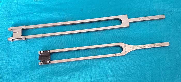
and Kleinschmidt went back into the business of building their own
teleprinters as Kleinschmidt Laboratories, Inc. During WWII,
Kleinschmidt demonstrated a portable, 100wpm teleprinter machine to the
Navy. The Navy ended up purchasing the machines which became a standard
for the Navy (along with several varieties of Kleinschmidt and Teletype Corporation
machines.) Kleinschmidt is still in
business as Kleinschmidt Inc., doing business in electronic data
exchange equipment.
Teletype Corporation operated with a slightly different business
model in that they could sell directly to other companies outside of the
Bell System, which eventually included sales to all branches of the
military. From pre-WWII up into the late-1970s, Teletype machines were
used in almost all business communications for most companies. Most
business product
ordering was by TELEX.
Teletype machines evolved over the years
with several different codes tried but Baudot and then later
ASCII were the main successful codes used. The most popular
speed was 60wpm but 75wpm and 100wpm were also popular and, after about
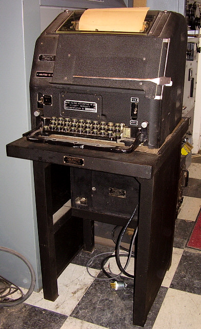
1950, most Teletype machines had a three speed selector switch. Early machines were
generally robust, heavy and usually fairly large. All early machines
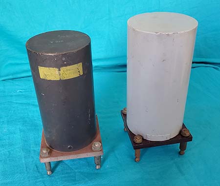
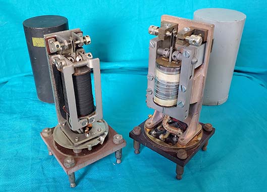
required routine maintenance to keep them running reliably. All wire TTY setups employed
polar relays to assure low noise on the line and reduce printing and
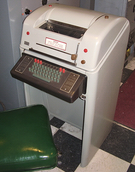
sending errors. Later machines, from the 1960s on, though
smaller and lighter weight, used plastic gears and levers, and were generally not the indestructible
behemoths of the 1940s (in many cases, the plastic hasn't aged well
either, becoming brittle and breaking easily.) As computers became
more and more powerful they were also being installed into much smaller,
light weight packaging. The computers required almost no maintenance
since they were virtually all electronic. By the 1980s, a Teletype
machine for company communications was becoming unnecessary and
ultimately
undesirable. By 1990, Teletype Corporation
was no longer in business.
There were three companies in the
USA that built teleprinters,...Teletype Corporation, Kleinschmidt
Laboratories and
Mite Corporation. Overseas in England, Creed built teleprinters. In
Germany, Seimens & Halske along with Lorenz built teleprinters. In
Italy, Olivetti built teleprinters. |