|
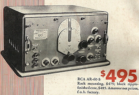
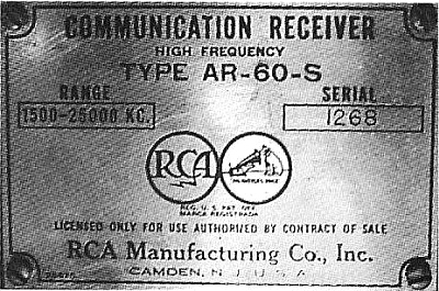
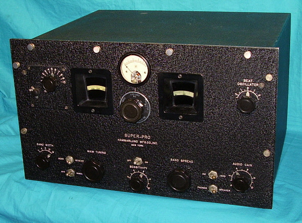
AR-60-S - This was the Deluxe version with two-tone gray finish. The
top cover-cabinet was aluminum metal painted smooth gray. The receiver sat on a wooden base to
that was also painted smooth gray. The panel was a slightly different shade of
gray and was "ripple finish" (RCA's advertising name for
wrinkle finish - which is the name used in the RCA AR-60 manual.) Dials and control escutcheons were light
silver color with black nomenclature. This is the version generally seen
in all advertising from RCA and consequently is the most often seen
photo version of the AR-60. Selling price was $495.
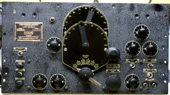
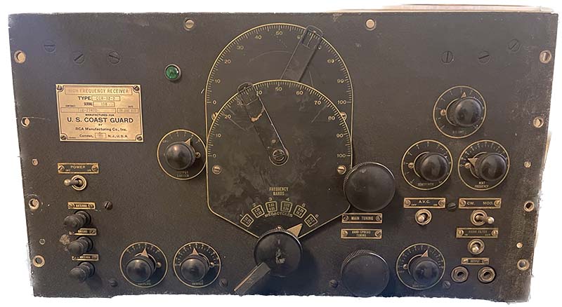
AR-60-T -
This was a Table top version that had a black "ripple finish" panel with black dials and escutcheons on
the early versions. Later versions had gray "ripple finish" panels. The panel is the same
width as the aluminum cabinet which was "ripple finish" painted the same color as the
panel. Selling price was $485. Some "T" receivers may have been supplied
with a painted wooden cabinet (see K4RAR Collector's Gallery.)
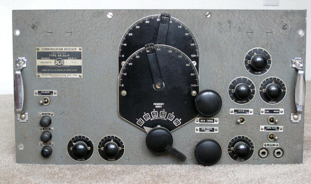
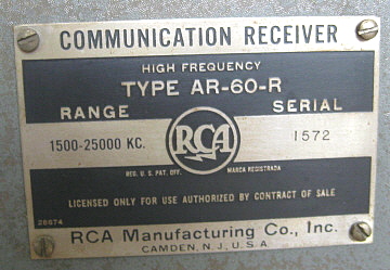
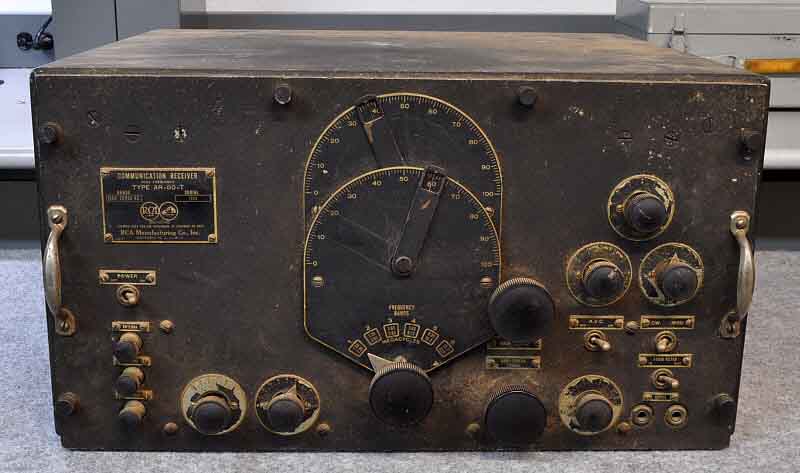
AR-60-R -
This is the Rack mounted version that had a black "ripple finish" panel with black dials and escutcheons
on early versions. Later versions had gray "ripple finish" panels. The
19" wide panel had
rack mounting holes not the usual slotted openings. The aluminum dust cover
was painted smooth finish black and secured with
two rear thumb screws that are on the rear of the cover. The dust cover entirely encloses the receiver chassis
(top, bottom, back and both sides.)
Selling price was $475
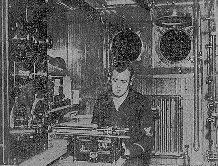
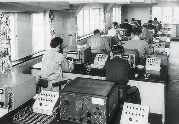
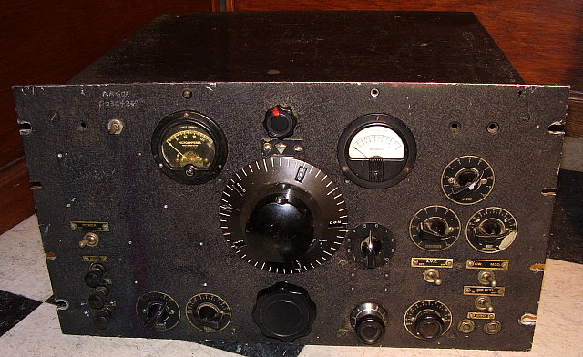
AR-60-G -
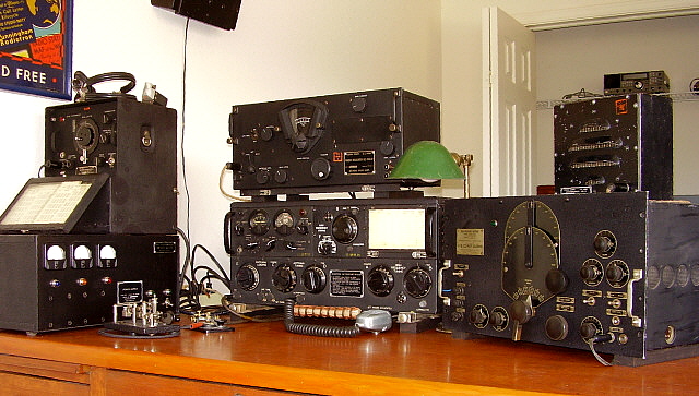
This was the U.S. Army Signal Corps version. Unfortunately the only known Signal Corps' photo
shows two different types of AR-60 receivers. Specifics are not known at
this time but receiver was certainly an AR-60-R version with some
changes for Signal Corps use. It appears from the
Signal Corps' photo (shown below) that both black and gray panels were
used.
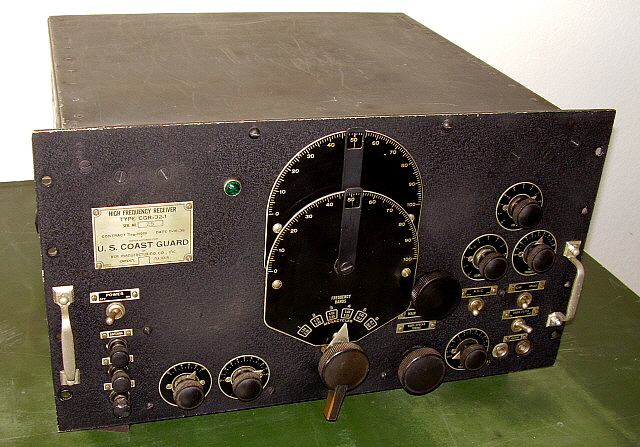
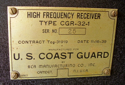
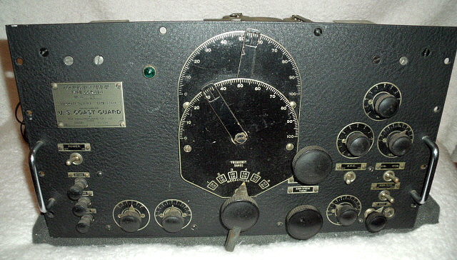
CGR-32-1 & CGR-32-2
- Special U.S. Coast Guard versions with black "ripple finish" panel, black dials and
escutcheons. Receivers are basically the AR-60-R with some minor changes. The first
contract for AR-60-R
receivers used by the USCG could have been designated as CGR-32 with no
specified "dash number," although
this hasn't been confirmed. It might be possible that the earliest
AR-60-R receivers used by the USCG didn't even have the
special CGR designation at all and were merely AR-60-R receivers. Certainly by 1937, the Coast Guard
designation of CGR-32-2 was in use (CGR-32-2 SN: 103, contract
Tcg-26741,
dated March 12, 1937 resides in the Hammond Museum in Ontario) which
implies that perhaps a CGR-32-1 contract existed before 1937. So far, the only
confirmed USCG models are CGR-32-2 and CGR-32-1. My Coast Guard receiver is
CGR-32-1 SN:25, contract
Tcg-31939 dated November 16, 1939.
USCG CGR-32-2 from Tcg-27470, 24 June, 1937 sn: 138
is owned by KN4R (reported
- 2023)
Andy KD6TKX owns a CGR-32-2 with a different set of numbers. It has
an "order number" rather than a "contract number." The info is:
CGR-32-2 SN:101, order TIPB 1651, date May 1, 1937.
As RCA Manufacturing Company, Inc. supplied the USCG with receivers,
it's probable that the initial batch of receivers were built under a specific
contract number with later receivers being built with the same CGR-32-1
or 32-2
designation but under different contract numbers. This
would be the same situation as the more modern R-390A receivers that
always have the same designation (R-390A/URR) but were built over a
period of several years under many different contracts. I would expect
that only a few CGR-32-1 and -2 contracts were issued between 1935 and 1939.
Each of these contracts were probably for small quantities of the
receivers. One has to remember that this time period was long before
WWII and the demands of the military in the 1930s were minimal.
Contracts from that time period are generally for 100 (or more often less) units per contract.
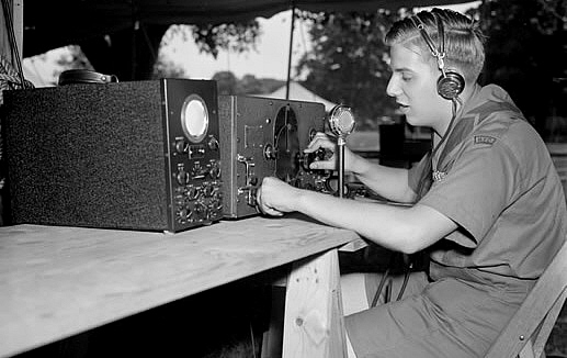
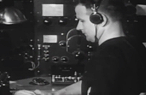
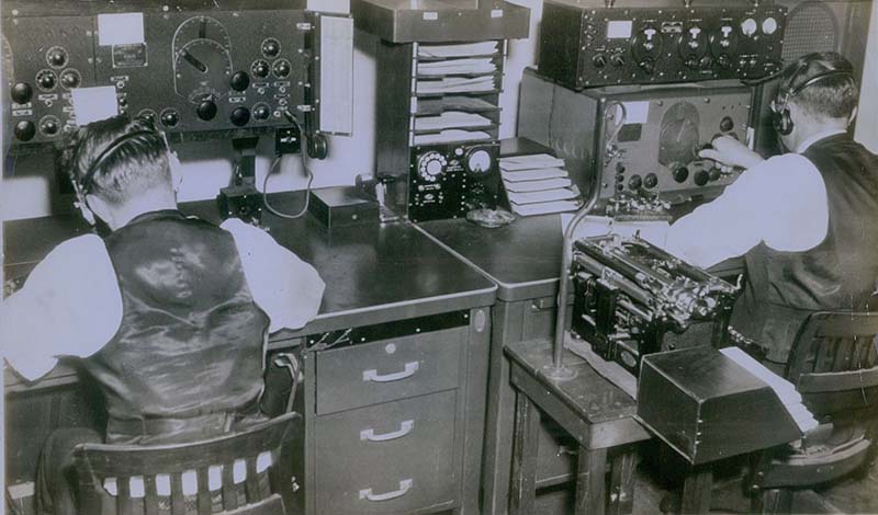
According to
Chief Radioman Leo G. Bellarts, in an article titled "KHAQQ Calling
ITASCA", the receivers used on the ITASCA in July, 1937 were CGR-32-1
types. Although this designation is outside of Bellarts' quote and was
added by the authors (David Bellarts and David Bowman) the information
must have come from Leo G. Bellarts. Other sources also identify the
USCG
ITASCA receivers as CGR-32-1.
A "new contract" for the CGR-32-1 was issued for the Coast Guard on
contract Tcg-31939 dated
November 16, 1939. This was probably the last
contract for CGR-32-1 receivers. Some of the variations noted on the
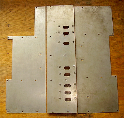
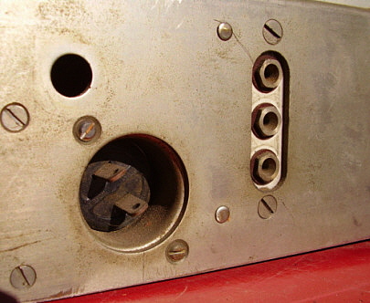
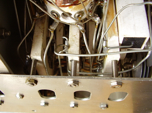
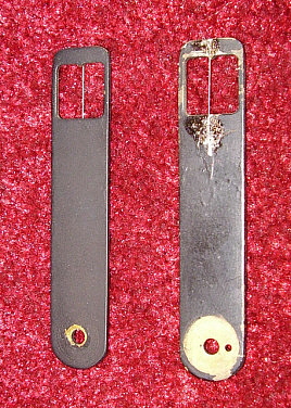
1939 CGR-32-1 included removal of the side antenna input jacks, possible
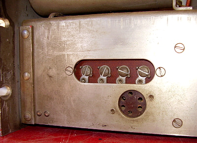
relocation of the AC fuse board from under the chassis to top of
chassis, modification of left side bottom cover with cutout portion to
allow access to antenna links. Whether all CGR-32-1 receivers have these
variations is not known at this time. These last "contract" CGR-32-1 receivers were supposedly to be
installed on the newly rebuilt "Lake Class" Cutters (ca. 1940.) It is
generally thought that about 30 "last contract" CGR-32-1 receivers were
built but perhaps this was the typical quantity of any of the CGR-32 contracts.
At present, we don't have enough information to report on what the
exact differences are between the CGR-32-1 and the CGR-32-2 versions.
|