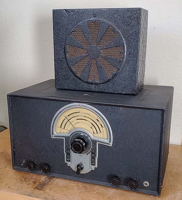
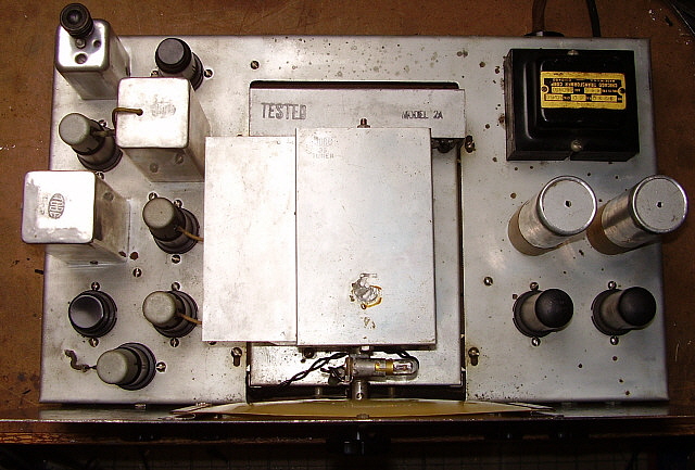
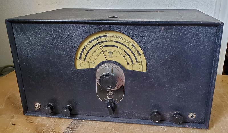
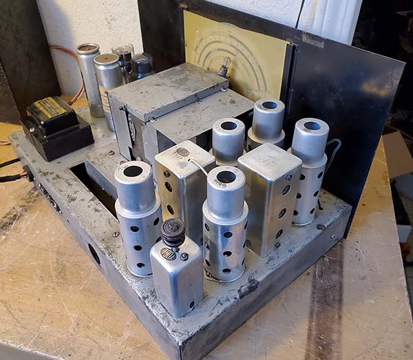
|
The Creation of Radio
Corporation of America, Superheterodyne Licensing and Gilfillan Bros., Inc.
In 1919, GE was working on a sale of
their important wireless patents, including the Alexanderson
Alternator, to the British Marconi Company (known as Marconi's Wireless Telegraph
Company Ltd. in England) When the U.S. Navy "got wind" of this intended
sale, they were livid. Especially since the information had come to them through
"ordinary trade channels." The Navy had just spent the past
few years (WWI) securing and protecting US wireless stations along with
protecting the transatlantic communication cables which were the sole
communications between the US and Britain during WWI*. Developing
reliable U.S. maritime radio communications was a top priority for the Navy and, here was GE, ready to sell
their major wireless licenses and patents to the Brits.
The Navy sent
their top brass, headed by Commander Stanford Hooper and Rear-Admiral William
H.G. Bullard, to GE to persuade them to not
sell USA wireless patents to a foreign nation, even if they were a
longtime ally. The Navy wanted GE to create a "radio company" that would
"do everything in radio." That would include
building equipment for the Navy, operating and maintaining
commercial wireless stations, building and selling radios and parts and, generally, be the exclusive manufacturer of
"all things radio"
for the United States and
especially for the
Navy.
Admiral Bullard, who was the newly appointed Director of
Naval Communications for the Navy Department, was able to convince GE's chief console and
vice-president Owen Young that this "radio company" was not only a patriotic
response to British Marconi's intent to purchase the USA wireless
technology but that such a "radio company" could be a very
lucrative arrangement for the GE. Owen Young convinced the other GE board members
that the sale to British Marconi should be
cancelled. In October 1919, GE set up the preliminary version of "the Radio Corporation"
using just their own assets. This didn't seem to be enough since no
manufacturing facilities were included, especially for
the type of company
the Navy (and now GE) had in mind.
GE knew that the American Marconi Company had long been concerned
that the majority of their ownership was in British hands. Ed Nally Jr, vice-president of American Marconi and A. G. Davis (of GE)
were sent to Britain to first, cancel the GE-British Marconi deal and to
second,
negotiate a new deal to buy American Marconi. Davis and Nally were
successful and were able to have GE buy the entire American Marconi
company, including their manufacturing plant in Adelaide, New Jersey. >>>
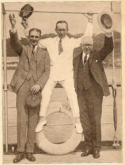
photo right:
Owen Young (left) vice
president of
GE and board member of RCA,
Guglielmo Marconi (center) of
Marconi's Wireless Telegraph Company Ltd. and
Ed Nally Jr.
(right) the first president of RCA. Aboard Marconi's yacht, Elettra, in 1922.
Photo from: "Radio Journal"
Sept, 1922
|
|
|
 |
>>> In November 1919, RCA was
officially formed and announced to the wireless world. Ed Nally Jr. was
the new president of RCA with Owen Young becoming a powerful RCA board
member. The RCA formation seemed set to launch the "Radio Corporation"
into the wireless business, but, at the last moment, General Electric
decided that too much strategic manufacturing power would be in the hands of RCA and that GE would
have little control of RCA operations. To have and maintain control over
RCA, GE retained the American Marconi plant for themselves and
essentially took all of RCA's ability to function as a manufacturer away
from them. RCA became what was essentially a sales agent for all of the
members of the "Radio Group," an unofficial name for the
patent-sharing and cross-licensed radio companies headed by GE. These
companies were RCA, AT&T, United Fruit Company and Westinghouse. RCA
sold radios and parts built by these companies (but, in most cases, with the RCA name on
them) through most of the twenties.
However, many of the old American Marconi
responsibilities became new RCA duties. The old Marconi Institute for
training radiomen became the RCA Institute performing the same function. Many of the commercial
wireless stations had to be maintained by RCA and, in some cases,
operated by RCA. This was how RCA operated
through the early-1920s. However, RCA was determined to become more than
just a sales-agent for the Radio Group and throughout the 1920s was
slowly purchasing various patents, developing the radio business and
growing into what the Navy had first envisioned. It would take a decade
of time and the
Federal Government to make it happen, though.
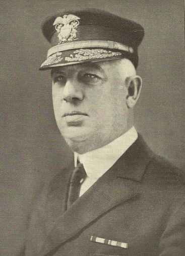
photo left:
Rear-Admiral William H.G. Bullard was Director of Communications for the
Navy Department. Bullard was instrumental in convincing GE to
form RCA.
Photo from: "Keeping the Stars and Stripes in the Ether"
- "Radio Broadcast" - June,
1922
* During WWI, Britain had laws in-place that prevented using
wireless for wartime transatlantic communications therefore all of these
important
communications between Britain and the US went by wire telegraph over the
transatlantic cable. The US Navy feared German submarines could have the
ability to destroy
these cables and seriously delay wartime communications. Thus the Navy
spent considerable effort to defend these cables against attack.
|
|
RCA during the 1920s
- Through most of the 1920s, almost all consumer-entertainment radio
manufacturing business for RCA was controlled by GE and to a certain
extent by Westinghouse. These two companies continued to build all of
the consumer radios that RCA sold during the twenties. RCA, though,
continued to buy other radio interests, radio patents and create other
businesses related to radio. In 1923, RCA bought Wireless Specialty
Apparatus Company from the United Fruit Company. This company
specialized in marine radio gear and continued to build that gear for
RCA to sell. Since this wasn't infringing
on the lucrative broadcast radio market, the Radio Group (minus United
Fruit Co.) didn't object. In 1925, RCA
bought a New York radio station and from that created the first network
broadcasting entity, National Broadcasting Company, or NBC.
In 1927, RCA was able to purchase the TRF patent (not the Neutrodyne TRF,...that belonged to Hazeltine and the Independent Radio Manufacturers.)
Additionally in 1927, RCA purchased Independent Wireless Co. and
combined it with Wireless Specialty Apparatus and created Radiomarine
Corporation of America, which became a subsidiary of RCA handling all of
the marine radio business.
In 1928, RCA got involved in the movie industry as part of RKO. RCA's
first president Ed Nally Jr. was president from November 1919 up to late-1922, at
which time he retired. Looking at the photo above (taken aboard
Marconi's yacht) one would think that Nally died but he lived on quite a
long time after retiring from RCA and died well-into his nineties (in the early
1950s).
RCA's second
president was a retired military man, James G. Harbord. He ran RCA
from late-1922 up until he retired in January 1930. Harbord viewed radio as a
powerful medium that was destined to grow and become an essential
resource for the business world and for daily human life. Most of his
"radio predictions" did become reality.
 |
David Sarnoff
becomes RCA President - January 1930
Harbord's retirement was to allow general manager David
Sarnoff, age 39, to become president of RCA. David Sarnoff had
been with American Marconi before it became RCA and had worked
his way up through the company. He was head of RCA up into the
1960s. Sarnoff is usually credited with starting NBC and with
developing the idea of broadcasting via networks of radio
stations.
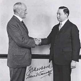
Photo left shows James Harbord (left) and David Sarnoff (right)
apparently depicting Harbord handing Sarnoff the "RCA reins."
photo from: www.sweetliberty.com |
|
RCA-Victor
Beginnings and the
1930 Anti-Trust Suit
- Around 1927, RCA was approached by the owners of the Victor Talking Machine Company. It
seemed that VTM Co's CEO Eldridge Johnson had been in declining health
and had sold his Victor interests to a banking syndicate in 1926. The
bankers now needed someone to run the failing Victor company, or to buy
it outright. RCA initially took over operation of VTM Co
manufacturing and began to incorporate GE or Westinghouse-built radios into elaborate combinations with
Victor phonographs. VTM Co. under Eldridge Johnson had viewed radio as a
competitor but now Victor created a few radios using the RCA held TRF
patent. These became the Victor Microsynchronous Radios found in many VTM
Radiola-Electrolas. These machines were moderately successful but RCA
really needed to "own" VTM Co to expand and develop their radio
business and become independent of GE. To purchase VTM Co was going to
require a substantial amount of cash - $15 million along with an
additional $15 million to convert Victor, essentially an old "victrola" manufacturer, into a modern, up-to-date radio
manufacturing company. Amazingly, RCA made a deal with General
Electric and Westinghouse to have them supply the needed cash "up front" in
trade for RCA stock to be transferred later down the road. Sarnoff was
running RCA at this time because James Harbord had taken a leave-of-absence
through most of 1928 to campaign for Herbert Hoover in the presidential elections of 1928.
Harbord retired in January 1930 to allow 39 year old David Sarnoff to
then become
president of RCA. The Victor factory in Camden,
New Jersey was converted to a radio factory by late-1929. RCA created a couple of
small companies, "Radio-Victor" and "Audio-Vision Appliance" to operate VTM
Co. This cumbersome arrangement was quickly changed to one company
called "The Victor Division of Radio Corporation of America"
better known as "RCA-Victor." Almost immediately, the federal government
stepped in and served up an Anti-trust suit against everyone that was
left in the old "Radio Group." At the time the suit was filed, that included GE, Westinghouse, RCA
and AT&T. The government singled-out GE and Westinghouse for punishment.
RCA was singled-out for rewards.
The settlement turned literally
everything "radio" over to RCA. The superheterodyne patent that had been
owned by Westinghouse was now RCA's. Additionally, all of RCA's debt to
GE and Westinghouse (involving the VTM Co. deal) was cancelled. Also, GE and Westinghouse couldn't
compete in radio with RCA for two years (they actually had to buy
RCA-built radio chassis to install in their own cabinetry until 1933.) RCA came out of the settlement
not powerful in radio,...they were
OMNIPOTENT in radio. They owned or controlled almost all aspects
of radio. All "legal" radio manufacturing in the US required a license from RCA. In essence, the government had stepped in and re-created RCA
into the "all-powerful" entity that the U.S. Navy had wanted eleven years earlier. |
|
Superheterodyne
Licensing, Sub-contractors
and the Gilfillan Bros.,Inc.
The anti-trust settlement also stipulated that RCA would now have to license other
manufacturers to build superhets. Every major radio company had to have the RCA
Superheterodyne License in order to remain competitive even though there were
royalties, certain rules to be followed and other conditions with having the license. By mid-1930,
most of the major radio companies had their superhet licenses and were
designing their new models for the 1931 sales year (Fall 1930 to Spring
1931.) However, some of the conditions required that the manufacturers had to produce radio chassis in sufficient quantity and of high quality in order
to qualify for the RCA license. This left many small companies unable to qualify for the
license due to their limited market, small overhead and the expenses involved in producing
high quantity and high quality chassis.
Fortunately, for the small radio companies, there
was a option in the RCA license rules and conditions that allowed a license-holding
company to build chassis for other un-licensed companies. Gilfillan Bros., Inc. in Los
Angeles, California had the only RCA Superheterodyne license in the West
(exclusive license-holder for 11 Western states.) This arrangement was the
result of a 1928 "face to
face" confrontation between S. W. Gilfillan and David Sarnoff, (who admired
Gilfillan's determination.) At the time of the Sarnoff-Gilfillan meeting, James
G. Harbord (RCA President from 1922 to 1930) had taken a leave of absence to
campaign for presidential-candidate Herbert Hoover and that left general manager, David Sarnoff, in
charge. The Sarnoff-Gilfillan arrangement was the offer of exclusive RCA
licenses in exchange for closing all Gilfillan operations not in the
Western States. Specifically, the Gilfillan plants in Kansas City and New York
City were the
apparent targets of the agreement. At the time, this licensing was mainly for TRF
circuitry but, in 1930, the superheterodyne was added to Gilfillan's exclusive
licensing. >>>
|
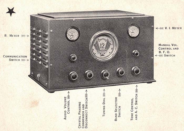
>>> Gilfillan allowed
subcontractors to build their own chassis on the second floor of the Gilfillan
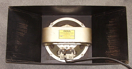
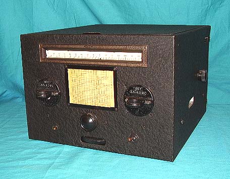
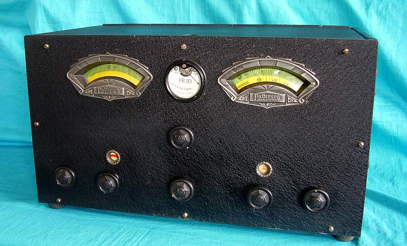
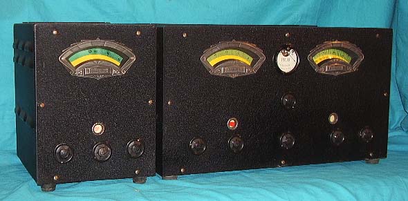
plant. This included Los Angeles companies such as Patterson, Breting, Jackson-Bell,
Packard-Bell, Kemper and Pierson-Delane along with dozens of other smaller companies,
all in the Los
Angeles area. During the early 1930s, the sub-contractor policy was not very strict and the
complete radio
didn't have to be totally assembled by the licensed company. Some
sub-contractors only had the radio chassis and cabinets built and then completed assembly themselves. The subcontractor was
protected because he was building the radio using a chassis supplied by the licensee
and the building process was supervised by the licensee. Some companies (including Gilfillan) allowed sub-licensed
companies to supply their own assemblers, set up their own production lines,
utilizing plant stock and tools, using plant
floor space at the license holder's company.
The sub-licensing policies
allowed many small radio companies the start-up operations because the major
expense, that is, purchasing real estate, building a factory, purchasing equipment and
production stock expenditures were
eliminated. This left the new radio company/sub-contractor to only have to hire
personnel and have a good design to build. During the Depression, this really
was the only option for a small company to produce quality radios, be able to
sell those radios and profit from that business. Also, those profits were shared
by the licensed
company (5% to Gilfillan which they split with RCA.) The subcontractor licensing
allowed everyone involved to profit during the difficult economic times of the 1930s.
There was the added benefit to the would-be purchasers that, because the
subcontractor radio company's overhead was so low, the radio products could be
sold for a much lower price and still net a profit for that subcontractor and
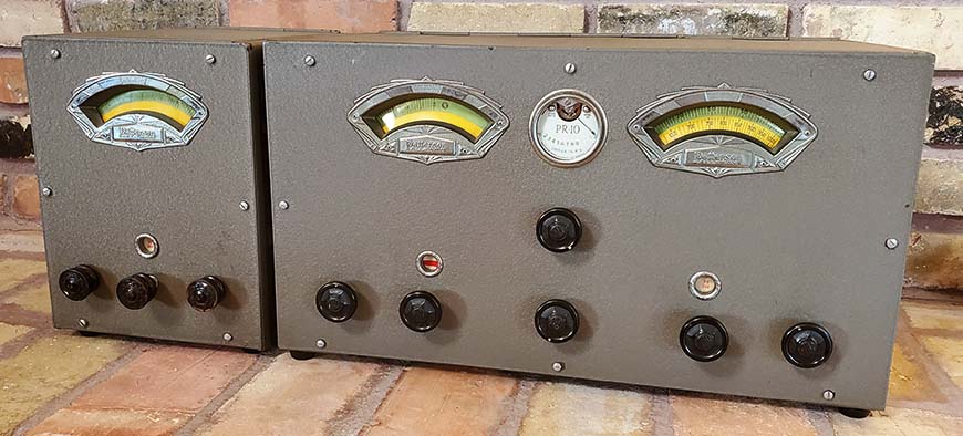
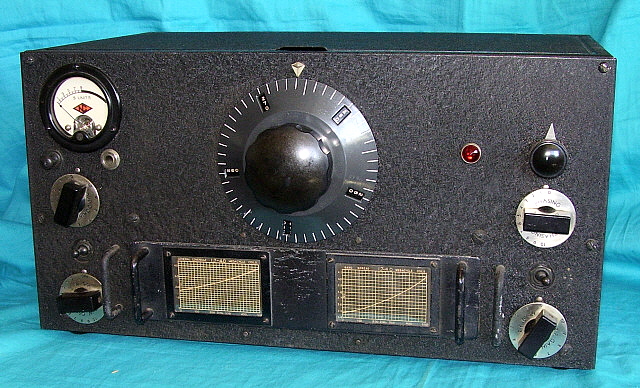
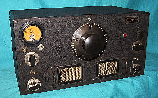
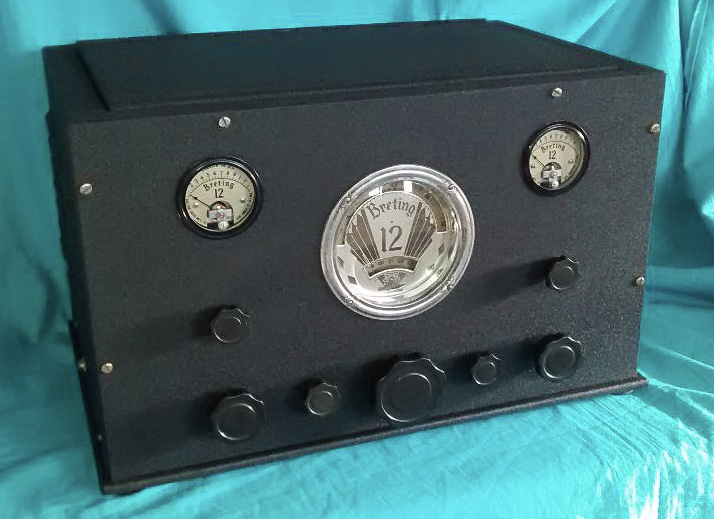
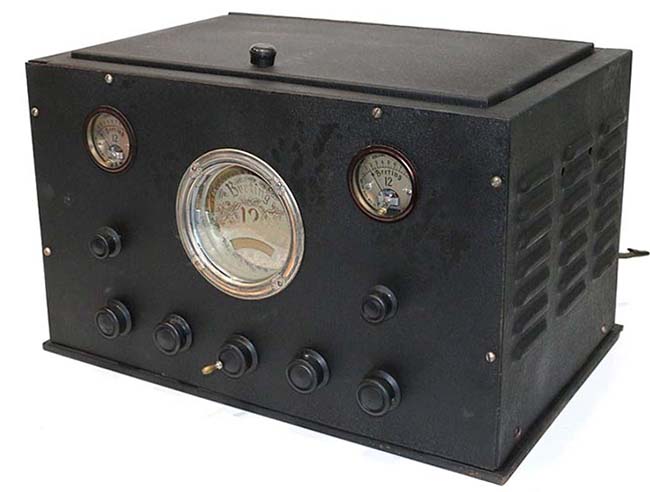
for Gilfillan. On average, Breting and Patterson receivers sold about 40% to 50%
less than a comparable National or Hammarlund product and about 30% to 40% less
than a comparable Hallicrafters product.
In 1940, RCA decided
that there was not enough quality control on the chassis produced for the smaller
companies by the license holding companies and began to stop allowing the sub-licensing
option. The RCA license structure was also changed at that time to allow most smaller
companies to obtain their licenses direct from RCA. However, Patterson had quit
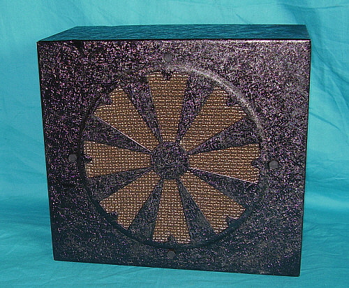
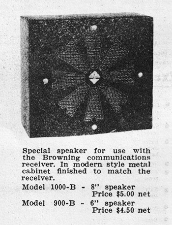
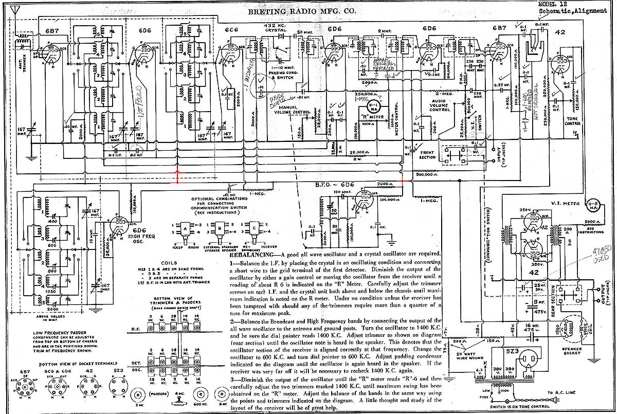
the radio business in 1939 and his major West Coast competition, Breting Radio
Manufacturing, quit the radio business in 1940.
|
|

