Radio Boulevard
Western Historic Radio Museum

 
WHRM Radio Photo Gallery
 

Post-WWII Ham Gear
1946 to 1960+

 Amateur Radio Receivers
 and
Amateur Radio Transmitters


I1LOV, Augusto Lovisolo, Varese, Italy  (ca:1958) with Collins KWS-1 and 75A-4  (photo from his QSL card.)

Post-WWII Ham Gear -  1946 to 1960+


National Company, Inc.  -  HRO-5A1, HRO-5C, HRO-6, HRO-7 


HRO-5A1
- At the end of WWII, most manufacturers had been building for the war effort since 1942. They didn't have anything new or ready for production for the 1946 model year. National offered the WWII version HRO-5 in late-1945 as their new table model receiver. The HRO Senior had evolved through WWII but by the end of the war, it still didn't look very different than the old pre-war receiver. The major changes during the war involved the crystal filter design, the changeover to metal octal tubes, a new non-ventilated cabinet and the use of mostly JAN parts. These late-WWII receivers were designated as the HRO-5 and the HRO-W. The first HRO-5 receivers offered after WWII were models that didn't have the bandspread coil sets. In a short time period (probably by 1946,) bandspread was added to the A, B, C and D coil sets and the receiver designated as the HRO-5A. As with the late-WWII coil sets, the post-war coil sets used a single aluminum plate with silk-screened graphs. Many of the HRO receivers sold by National in the early post-WWII period will have several variations that seem to confirm that National was trying to "clear out" old stock. Many post-WWII HROs will be found with pre-WWII S-meters installed. Several front panels have turned up with extra holes for the long data plate used on the HRO-W. Expect to find many variations when examining HRO-5 receivers sold up to about mid-1946. By mid-1946, the HRO-5A1 replaced the HRO-5A and added a noise limiter to the circuit (built on a small chassis mounted on the large chassis.) When the receiver was in a table top cabinet it was designated as the HRO-5TA1 (rack mounts were HRO-5RA1.) The HRO-5A1 used 12 tubes - two additional tubes were necessary for the noise limiter circuit. Early versions of the HRO-5A1 may be found with the round S-meters, earlier surplus front panels which will have the National HRO-5A1 tag mounted just above the Noise Limiter control and many other minor variations that show that National was still trying to clear out old stock. The "last version" of the HRO-5A1 receivers will have a square S-meter, cadmium-plated chassis, Noise Limiter is built directly on the chassis, a stepped-switch Crystal Filter Selectivity control and plastic insulated wire under the chassis in the wiring harness. These receivers are consistent in construction using all new parts and components. All of the "last version" HRO-5A1 receivers were built on production run 184 and a small quantity on run 189.


photo above: HRO-5TA1 SN:184 1054 is how the last of the black wrinkle finish versions of the receivers looked. SN: 184 1054 is the highest reported HRO-5TA1 serial number in run 184, so far.
HRO-5C "Deluxe Receiver" - The HRO-5C was considered a "Deluxe Receiver" because the total package included the HRO-5RA1 receiver, the SPC panel that included an 8" loudspeaker, Model 697 power pack and spare coil set storage unit. A chassis-built Model 697 power pack was mounted on top of the rear part of the coil box directly behind the loudspeaker. The coil storage had bays for five coil sets. With one coil set in the receiver plus five in the bays, coil storage capacity was six coil sets. This was usually sufficient for standard coil sets D, C, B and A in addition to the most commonly purchased optional coils sets, F and E (AM BC band and 160M general coverage.) The receiver and the SPC were both mounted in a MRR table rack that was 29 inches tall. Black, wrap-around side trim pieces covered the rack mounting screws and three stainless steel trim pieces finished the installation of the HRO-5RA1 and SPC into the MRR rack. The 1947 selling price of the standard table model HRO-5TA1 with coils, power pack and loudspeaker was around $300 from most dealers. The HRO-5C selling price was almost certainly close to $400. The HRO-5C was available from mid-1946 up to mid-1947 when the HRO-7 was introduced.

The HRO-5C shown to the left is SN: 184 0009, a very early example from run 184. It probably dates from August 1946 and was probably sold in the Fall of 1946. Almost all "last version" HRO-5A1 receivers were built on the 184 production run with a small quantity on run 189 (run 189 was mostly HRO-7s.)

HRO-6 - In late-1946, a handful of HRO-6 receivers were produced in a very small production run within run-184, the same production run designation that was used for "last version" HRO-5A1 receiver. The HRO-6 is identical to the "last version" of the HRO-5A1 receivers with the only difference between the HRO-5A1 and the HRO-6 being the identification tag. The commonly referenced Noise Limiter circuit "difference" actually was incorporated into the HRO-5A1 receivers at the beginning of run-184. National designated only some of the HRO-5A1 receivers built after July, 1946 as the "HRO-6." It appears the change to HRO-6 started around sn: 184 03xx and continued until around sn: 184 07xx. At present, only one HRO-5A1 receiver has been reported within this serial number range. It's doubtful that 400 HRO-6 receivers were produced. With only two reported serial numbers, the inference would be less than 100 receivers were tagged as HRO-6. This assumption implies that the HRO-6 and HRO-5A1 designations were intermixed during production.

National must have considered that the ham consumers might assume that the HRO-6 would be National's "new 1947 model" since it appeared in late-1946 (when the "1947 models" were usually announced.) National was actually doing the engineering design work for their new model HRO that eventually became the HRO-7. National dropped the HRO-6 designation and quickly changed back to using the HRO-5A1 designation. National apparently didn't want the hams thinking that their new 1947 receiver looked just like the pre-WWII HRO receivers. Several hundred more HRO-5A1 receivers were built on run-184 after the HRO-6 designation was dropped. The HRO-7 was announced in August 1947.

HRO-7 - For 1947, the HRO-7 was introduced and this receiver totally changed the appearance of the black wrinkle finish HRO. The HRO-7 was light gray smooth finish, the cabinet was modernized with rounded corners, the S-meter was mounted behind the panel and viewed through a cut-out and the knobs were restyled. The matching speaker was also restyled to match the new HRO-7's appearance. Internally, a voltage regulator was added and the LO changed to a 6C4 miniature tube. Coil sets were changed to not employ handles for removal but utilized levers instead. Additionally, the graphs and charts were replaced with a linear calibration scale. Although the physical appearance of the HRO-7 changed dramatically, internally most of the updates to the HRO-7 were rather conservative. The HRO-7C offered the rack mount HRO-7 in black wrinkle finish with the SPC and MRR rack.


National Company, Inc. - NC-240D (aka: NC-2-40D)

National's "Moving Coil" receivers utilized a cast-metal catacomb that carried the various front-end coils and placed them into contact with the tuning condenser by way of small contact pins and pin-receiving contacts. The catacomb was rack and pinion driven with a large knob on the front of the receiver. The initial "Moving Coil" receiver was the 1936 NC-100. In 1940, the NC-200 was introduced and it featured both general coverage coils and amateur band spreading coils. During WWII, National produced the NC-200 receiver for various uses. However, like most military receivers, the amateur band spread function was eliminated. These receivers were designated as the NC-240CS. Immediately after the war ended, National did sell some NC-240CS receivers to the civilian market but most were considered "commercial" receivers. The NC-240CS was also used as an Airways Receiver designated the RCR. In a short time, National reinstalled the amateur band spread and designated the new receiver the NC-240D although some ads and a few manuals show the model as NC-2-40D (this was probably a literal representation of vocally how the model was referred to,..."NC two-forty D.") The NC-240D added metal pedestal feet to the receiver cabinet. The single large knob that provided tuning when pushed in and changed bands when pulled out was unchanged from earlier versions of the NC-200 series. Initially, the NC-240D was supplied with the round flange Marion Electric S-meter, which was the same S-meter used in many pre-war National receivers including the HRO Senior. By 1947, the round flange meter was replaced with a square flange S-meter, also from Marion Electric.


NC-240D from 1946

Note in the photo above-right, the NC-240D dial has all of the Band Spread scales near the center of the circular arc of the dial. Later NC-240D dials will have the Band Spread scales directly above the A, B, C and D General Coverage bands (see lower photo.) Production of the NC-240D continued through most of 1948. The NC-240D was the last of the "Moving Coil" receivers produced by National - a design that was produced from 1936 up through 1948 and included the famous WWII Navy RAO line of receivers.

The NC-240D is a single preselection receiver with two stages of IF amplification. A Crystal Filter is provided as is a Noise Limiter and a Tone control. The audio output is from push-pull 6V6 tubes but the audio circuitry utilizes a phase inverter rather than an interstage transformer (National began using the phase inverter circuit with the NC-200 in 1940.) The matching speaker (also with chrome bars and pedestal feet) had the P-P audio output transformer mounted to the frame of the 10" Jensen speaker (so, ideally, each NC-240D should have its matching speaker included in the sale nowadays.) The phone jack on the left of the front panel is for headset operation while the phone jack on the right is an audio input (for phonograph or similar device.) Since National had lots of "left-over parts" from the war production, the early versions of the NC-240D do have many small variations from receiver to receiver (just like the HRO-5.) The chassis appears to have been punched for many variations so expect to find almost any NC-240D to have unused large holes in the chassis. By the later versions, most of the parts are standardized and the receiver produced was consistently the same.  National used "T" in the model number to indicate that the receiver was in a table cabinet while "R" was used for the rack mounted version.

The NC-240D can be an excellent vintage receiver in a vintage ham station. The receiver is fully capable of excellent sensitivity and can cope with just about any type of QRM. The audio reproduction is excellent if the original loudspeaker is used. A full rebuild is usually necessary followed by a complete IF and RF alignment to achieve the performance that these receivers are capable of providing.


photo above: NC-240D from 1948 (last production run) showing how the late-builds look.


The original 1946 Hallicrafters S-38 used six tubes, had a real BFO and had a Noise Limiter circuit.

the Hallicrafters, Inc.  -  S-38 Series

The S-38 was a post-war continuation of the "introductory" type receiver line, characterized by the pre-war Sky Buddy series. Intended to introduce young radio enthusiasts the shortwave broadcast reception, the S-38 was low-priced, easy to operate and most users were able to get decent performance results considering the receiver's obvious circuit limitations. Introduced in 1946, the initial S-38 had six tubes with Bandspread, BFO and Noise Limiter circuits. All of the S-38 series receivers were AC-DC operated. Shortly after its introduction, the circuit was changed to a five tube set with no noise limiter and a CW position that used a gimmick to actually set-up a regenerative oscillation in the IF. There certainly must have been complaints about the performance of these later S-38s since CW is next to impossible to receive with the IF amplifier in oscillation. The gimmick used was a length of wire under the chassis that is moved around until the regenerative oscillation seems like it might allow CW copy. Needless to say, most youngsters were listening to SW BC and hams on AM phone anyway (unless they really wanted to become hams - then good CW performance was important.) S-38 versions A, B and C have semi-circular dials while the D and E versions have slide-rule dials. Selling price was around $40 in 1946 but by production's end, in 1961, the price had climbed to $55. The first version cabinet was designed by Raymond Loewy, though Loewy actually won an award for the SX-42 cabinet design.

Also available were two custom finish S-38E models. These were the S-38EB, a blonde faux finish version and the S-38EM, a faux mahogany finish version (shown to the right.)

The faux mahogany finish of the S-38EM

Lafayette - KT-200 - aka: Trio HE-10 or "S-38 Look Alike"


If you really loved Raymond Loewy's original S-38 exterior design BUT you knew that the circuit of the S-38 just wasn't capable of "on the air" communications AND you didn't mind spending a little bit more money AND you also didn't mind assembling your new receiver, then you could invest in the Lafayette KT-200.

In 1959, Lafayette began selling a receiver kit that was designed and produced by Trio of Japan (later to become Kenwood.)  The KT-200 was essentially the Trio HE-10 in "kit form." When assembled, the new owner had a receiver that was capable of "on the air" communications. With a tuned RF stage and two stages of IF amplification along with bandspread tuning, an S-meter and an AC operated power supply, the KT-200 was pretty much a standard "ham receiver." The superheterodyne circuit used nine tubes and was "miles ahead" of the S-38 in performance. The KT-200 also had a real BFO and could copy CW without too many headaches. The receiver front-end and IF transformers came "pre-aligned" to ease assembly and final testing. As would be expected, dial accuracy was vague at best. For about $70 and a few hours of assembly and final testing, the new KT-200 owner had a receiver that looked like a Raymond Loewy creation (actually like a S-38 on steroids) and performed well-enough to actually use "on the air." Whether the operator was a Novice ham and or a frugal but experienced ham, the KT-200 could provide decent reception. Some users would add a Q-multiplier to help with selectivity. There was also a matching loudspeaker available. The KT-200 was available from 1959 up to about 1964.  


the Hallicrafters, Inc.  -  SX-42

The SX-42 was introduced in mid-1946 as the post-war successor to the company's former "flagship" - the SX-28A. The SX-42 was a complete departure from the usual receiver styling of the time. Well-known industrial designer Raymond Loewy created a receiver exterior that didn't look like any piece of radio gear that had proceeded his futuristic, award-winning design. The main tuning escutcheon with its green tinted plastic and green main tuning dial resembled something from under a then modern jet canopy. A coaxial tuning system allowed the user to "lock" either the main tuning or bandspread tuning depending on which was going to be used. Besides the ultra-modern exterior, the receiver circuit boasted a very wide frequency coverage of .54 to 108MC with the addition of Frequency Modulation capabilities from 27 to 108MC. The receiver used 15 tubes like its predecessor the SX-28A did but a Converter tube is used rather than separate LO and Mixer tubes. Additionally, a VR tube was included along with Limiter and Discriminator tubes for FM. The SX-42 was single-conversion with double pre-selection on all bands (except band 1, AM-BC) using two seven-pin miniature tubes for RF amplifiers (6AG5 tubes.) Four Loktal type tubes were also used in the circuit and the remaining nine tubes were standard Octal types. The audio circuit used P-P 6V6 tubes and provided 500Z ohm and 5000Z ohm outputs. Selling price was $250 but, by 1947, the price increased to $275. There were several matching speakers available but the R-42 table-top bass-reflex speaker is generally pictured with the receiver in Hallicrafters' advertising. Another accessory was a table top "Tilt-Mount" on which the receiver was placed. The Tilt-Mount then allowed the entire receiver position to be moved in any angle to allow a comfortable view the receiver front panel.

Early versions of the SX-42 will have a greenish colored bezel on the bandspread dial and a black background "h" emblem on the dial. Later versions have a light gray bezel on the bandspread dial and a silver background "h" emblem. The are a multitude of engineering upgrades to the circuit and manufacturing process all through the SX-42 production.

The SX-42 was really never a very popular receiver with hams. Certainly the expense of the receiver was an important issue for many but its unusual looks, which hams may have been considered "too modern" in the then age of "wrinkle finish black panels," may have also been a factor. The coverage of the then new FM band (88 to 108MC started in 1946) may have made hams feel that the receiver was more of an expensive luxury for the well-to-do consumer than for a typical budget-minded ham. At any rate, production of the SX-42 was stopped in early 1948 - a fairly short lifespan for a "flagship" receiver. The SX-62 took the SX-42's place as the high-end Hallicrafters receiver but it seemed to again be more for the consumer market and few hams bought them as their station receiver. The popular SX-71, certainly designed for hams, filled in that portion of the ham communications receiver market after the demise of the SX-42.

Today, the features that resulted in the SX-42's only moderate success are what attract collectors to the receiver - the futuristic styling (which won an International Design Award for Raymond Loewy from the NY Museum of Modern Art,) the wide-swing FM-BC coverage, the fabulous audio (when using the proper Z speaker) and the relative rarity of finding an example in nice cosmetic condition all contribute to the SX-42's desirability. Additionally, the SX-42 is featured in a plethora of late-forties "B" movies, from Gene Autrey to low-budget science fiction movies, early TV shows like Sky King, meaning that SX-42 fans can regularly spot their favorite receiver in a multitude of film backgrounds.

Shown in the photo to the left is a later version of the SX-42 along with the matching R-42 bass reflex speaker. This combination was purchased for K6HUZ by his father as a special gift for passing the General Class license exam. It was 1954 and the SX-42 and R-42 were found in a pawn shop not far from the Federal Building, where the FCC administered the amateur exams, in downtown Los Angeles. K6HUZ kept the receiver and speaker in great condition for 57 years, then donating it to our museum.

The photo above in the header shows an earlier version of the SX-42. I found this receiver in a backyard shed in Gardnerville, Nevada. It had been the victim of poor troubleshooting and had several modifications to the circuit trying to correct a fundamental mis-wire that happened when the filter capacitors were replaced. I had to strip out the IF section of the receiver and rebuild it to stock. I went ahead and fully re-capped the receiver. It now works fabulously with great audio and respectable sensitivity. I have yet to have the "gun metal dark gray" paint matched so I can restore the cabinet on this early version SX-42


James Millen 90800 Exciter with gray finish

James Millen Mfg. Co., Inc.

90800 - 50 Watt Exciter

James Millen left National Company in May, 1939. Millen's story was the departure was to start-up his own business although there were many other reasons that influenced his decision. Most of Millen's products were mechanical parts and various types of components and assemblies. Some products were based on popular projects that had appeared in QST magazine. The "Swing-Arm VFO" and this 50 watt Exciter were a couple of examples that started out as QST projects. Though the first couple of decades, Millen's products didn't change. Later, some updating was applied to the more popular items with gray paint replacing black wrinkle finish. Millen really didn't make any money on his ham products. James Millen Mfg. Co. primary and most successful business was as a contractor building oscilloscopes for RCA and two-way radios for GE.

The 90800 was available just after WWII ended. The price was about $40 without tubes or coils. The oscillator is a metal 6L6 tube that can be either crystal controlled or can be operated with a separate VFO. The PA is an 807. Plug-in coils are used for the oscillator grid, oscillator to PA coupling and PA output. Coils were available from Millen. A separate power supply was required and, although Millen offered one, most hams built their own. Most of Millen's products for hams were component units that would be used to build-upon and then, with a few other components and some homebrewing, a complete transmitter could result.


Collins Radio Co.  -  75A-1 
 

Art Collins began selling amateur transmitters in the early thirties. High quality and great performance brought in commercial and military customers making Collins Radio a major supplier of radio equipment during WWII. Collins entered into the communications receiver market after WWII with a double conversion superheterodyne receiver that was entirely permeability tuned. Using a precision Permeability Tuned Oscillator (called a PTO - Type 70E-7) along with a multiple crystal controlled oscillator and by keeping the maximum coverage of each band to just 1.0 MC, Collins was able to achieve 1.0 KC accuracy in the dial read out with receiver stability that was incredible. The linear dial system features "band in use" illumination and requires twelve #328 lamps - two lamps for each band. The 75A was an introductory model that was probably not produced in any quantity. It was superseded by the 75A-1 in 1947 - the only noticeable difference was the addition of a Noise Limiter circuit with a front panel switch. Though the 75A-1 is a 1947 design, the receiver's performance is a pleasant surprise - more like a receiver from the 1960s with impressive stability, dial accuracy, sensitivity and selectivity. The 75A-1 is a first-class receiver for a vintage ham station with performance that is still competitive, even on 10 meters. Audio in the AM mode may be considered somewhat restricted due to the 75A-1's excellent selectivity but, after all,  it is a ham bands communication receiver. The 75A-1 receiver shown is SN: 1832.

See the 32V-Series web-article for details on rebuilding the slide rule dial. The 75A-1's dial is virtually the same and is rebuilt in the same manner. Use Home-Index at the bottom of this page for navigation.


Collins Radio Co.  -  32V Series Transmitters

32V-1 - The 32V-1 transmitter was introduced in late-1946. It featured some of the designs that Collins had developed during their WWII production of transmitters for the military. The 32V Series of transmitters use a Permeability Tuned Oscillator, a PTO, as the VFO-Master Oscillator and several tuned multiplier stages to create a tracking exciter that allows the transmitter to stay "in tune" as the frequency is changed. All that was required of the operator was to set the frequency and then "match" the transmitter output to the antenna impedance. Other than the Pi-network, all circuits were automatically tuned as the frequency dial was adjusted. Collins used their coil-slug rack carriers in the frequency multiplier section and full permeability tuning is used throughout the oscillator and multiplier stages. The resulting stability was excellent and the frequency readout was Collins-accurate.

The PA tube is a Raytheon 4D32 and the 32V Series allowed selectable plate voltage - either +600 or +700vdc -  the lower voltage allowing the 4D32 to run at the manufacturer's specifications for continuous duty and also allowed for reduced output power for driving other devices. The 4D32 tube itself is notorious for developing gassy conditions so be sure to stock several spares. The modulator tubes are the ubiquitous 807s. The power input was rated at 150W CW and 120W Phone. Audio response is 200hz to 3000hz and the power output on AM phone is generally around 100 watts if +700vdc plate voltage is used and about 65 watts output if +600vdc plate voltage is used. If the +600vdc plate voltage is used, then the Modulator bias (chassis mounted pot adjustment) will have to be set lower to 50mA and the transmitter has to be loaded to around 180mA of plate current. On +700vdc plate voltage, plate current on AM phone is about 225mA and Modulator bias is 55mA.

The COARSE ANT LOADING control is located under the lid and mounted next to the Pi-network inductor. Changing bands or even a QSY from CW to Phone required lifting the lid to access this control for adjustment of the Pi-network loading.

32V-2 - The 32V-2 transmitter was introduced in mid-1948 and had many improvements over its predecessor, the 32V-1. The major change for the 32V-2 transmitter was the redesigned Pi-network ANT LOADING control that now adjusted both coarse and fine loading with one control movement of the front panel control - no more lifting the transmitter lid to adjust the COARSE ANT LOADING. The inconvenience of having to access the COARSE ANT LOADING under the lid must have been a source of customer complaints regarding the 32V-1. The 32V-2 integrated the coarse loading (switching in fixed-value mica capacitors to the Pi-network) as part of the front panel ANT LOADING control (air variable C) by using a Coarse Loading switch that advanced one switch position with each rotation of the ANT LOADING control. A turns-counter indicator was viewable through a small hole just above the adjustment knob. As convenient as the new ANT LOADING control was its misuse then made it easy for the operator to casually adjust the ANT LOADING across a C-switch point with the key down (while tuning the transmitter) and destroy the Pi-network fixed-value mica capacitors.  

The V-1 didn't have a "TUNE" position switch to allow low-power adjustments of the transmitter loading - the 32V1 had a green pilot lamp in that position of the front panel. The V-2 added a reduced power "TUNE-OPERATE" toggle switch to help protect the Pi-network fixed-value capacitors from switching transient damage if the ANT LOADING was allowed to advance the C-switch with the transmitter key down (or in the AM mode without a telegraph key installed in the key jack.)

As the 32V-2 was being produced (1948 to 1952) minor improvements to the power supply and voltage regulation were added (very late 32V-1 transmitters did add two series-connected 0A2 tubes as screen voltage regulators which became standard for the 32V-2.) Very late production 32V-2 transmitters had two series connected regulator tubes added, a 0A2 and a 0B2, for the PTO screen voltage regulation.


Collins 32V-2

32V-2 Pi-Network Problems: The Pi-network used in the 32V-2 is subject to mica capacitor failure due to the upgrade that moved the COARSE ANT LOADING switch from a chassis mounted component accessed under the lid of the transmitter to a front panel control integrated to operate in conjunction with the ANT LOADING control. This problem usually only affects the 32V-2 model when a telegraph key is not installed in the key jack. The telegraph key forces the operator to hold the key down for tuning and loading functions. This usually prevents the operator from casually crossing the ANT LOADING C-switch points with the key down. Without the key installed in the jack, the transmitter is always "key down" and it becomes far easier to accidentally cross the C-switch points at full power while adjusting the ANT LOADING control.

The 32V-2 transmitters used five fixed-value mica capacitors in the Pi-L Network. These mica capacitors were rated at 2500wvdc. There are three micas that are fixed-C values for 80M and 40M Pi-Network operation. It seems to be common for one or more the three capacitors used in the network to fail. Symptoms are inability to tune the transmitter on 80M or 40M but operation on 20M and up is normal. The probable cause of the mica capacitor failure is loading the transmitter at full power "key down" (e.g., in AM w/o key in jack) while crossing the "COARSE LOADING" switching points while turning the ANT LOADING control. It's likely that the "switching voltage transients" destroy the mica dielectric causing capacitor failure. As the LOADING air variable is rotated, each turn of the control knob results in a change in the switch position for the fixed-value capacitors (COARSE LOADING) that are in parallel. The fixed-value capacitors are only used in position 1, 2 and 3 of the ANT LOADING so the failures only occur on either 80M or 40M (or both) operation.


Collins 32V-3

32V-3 - Introduced in 1952, the 32V-3 was the last of the 32V series of moderate-power, AM-CW transmitters produced by Collins. From the time that the 32V transmitters were first introduced in late-1946 up until the 32V-3 version, television broadcasting had grown explosively. Everyone was trying to receive TV broadcasts "out of the air" via their roof-top antenna. Many of these TV-fans were in rural areas ("fringe areas" as it was called for TV reception) and "over-the-air" TV signals in those areas were very weak requiring a large TV-yagi antenna mounted on a tower in order to receive a fairly clear picture. In addition to the TV signal strength problem, many early television circuits used a 21mhz IF strip for the video. At the time of design, 15 meters wasn't an accessible ham band although it was designated to become one. Additionally, the 21mhz IF was harmonically related to the 40 meter ham band. All of these potential TVI problems and their seeming insolvability seemed to restrict many hams from being able to operate in a neighborhood populated with roof-top TV antennas. As a result of this ever-increasing TVI problem, most of the commercially-built ham transmitters underwent considerable modifications in an effort to minimize harmonic radiation. Most manufacturers redesigned the mechanical housings of their transmitters to hopefully eliminate (or at least reduce) the harmonic RF emissions. Pi-L networks were incorporated to reduce harmonic emissions and 30mhz-cut-off, low pass filters were installed by most ham operators. Coaxial cables became the only accepted method to transfer RF from the rig to the antenna. As a result of the TV-boom of the early fifties, Collins redesigned the 32V-2 so it would be able to function in "TV-land" without causing interference (if the transmitter was set-up and operated correctly.)

There are several changes found in the 32V-3 and most were specifically for reducing TVI. Full shielding of the PA and antenna matching network is accomplished with a two-piece, wrap-around, purf-metal shielded cage. Lots of mounting screws assures good grounding and certainly makes any routine tube checking in the PA and multiplier sections (five tubes plus two regulators) a task. The antenna matching network was extensively changed to provide a more durable and higher-Q Pi-L network that reduced the possibility of harmonics making it to the antenna. The fixed-value, individual mica capacitors with the 2500wvdc rating were changed to series pairs that increased the working voltage to 5000vdc.

The cabinet was completely redesigned to be "RF-tight" by eliminating the access lid and, again, making any routine maintenance a "chassis-out-of-the-cabinet" job. Since RF harmonics had a tendency to radiate by getting into accessories, the Antenna T-R relay drive, receiver muting access and AC power inputs were all routed through capacitive bypass, feed-thru filters. Both meters now had filters on their terminals. Other updates included the 70E-8B PTO change (32V2 used the 70E-8A,) +LV power transformer and +HV input choke changed to hermetically-sealed units (also found in late-production 32V-2 transmitters) and changes to the rear covers necessary because of the Antenna T-R relay power, receiver muting and AC input updates. The 32V-2 had a built-in CW sidetone oscillator and since that required external connections to a reproducer that might contribute to harmonic radiation, the sidetone oscillator was eliminated in the 32V-3. Also, a separate filament transformer for the PTO tube along with screen regulator tubes for the PTO were added to the 32V-3 that aren't present on the 32V-2. The PTO filament transformer is actually a "hum-bucker" setup with the filament winding CT connected to the -75vdc bias line. The PTO tube filaments were not connected to ground so the -75vdc bias voltage "swamped" the AC on the filament and providing a DC voltage on the PTO tube filament. The "hum-bucker" eliminated any AC hum from modulating the PTO output. An additional filter capacitor was added to the -75vdc bias voltage supply to further filter any hum. The PA current specified in the manual was reduced from 220mA (in +700HV) for the 32V2 to 200mA (in +700HV) for the 32V-3. The reduction in PA current was probably to reduce the possibility of TVI due to excessive loading causing saturation of the PA tube.

The 32V-3 appearance is somewhat changed with "grab-handles" (left-over ART-13 handles) mounted to the front panel (since you were now going to have to withdraw the chassis from the cabinet to do any routine maintenance.) The cabinet was changed to have several patterns of vent holes in the top and sides. Also, the cabinet is slightly taller than its predecessor (due to large rubber bumper type feet.) Also changed was the interlock switch location. Since the cabinet lid was eliminated, the interlock switch was relocated at the rear of the chassis. Removal of the chassis from the cabinet opened the interlock switch which opened the +HV line preventing the complete operation of the transmitter outside of the cabinet. +LV and tube heaters were still operational so the transmitter can be aligned, that is, the PTO and Multipliers are operational but the Modulators and PA aren't.

The 32V-3 had its design influenced by an environment that was difficult for the ham radio operator due to the public's "over-the-air" TV BC reception. When cable-TV came on the scene, providing TV-fans with very strong signals routed through shielded cables, the level of ham-generated TVI was greatly reduced. Almost simultaneously with cable-TV's introduction, the popularity of SSB voice transmissions replacing AM voice also tended to greatly reduce TVI due to the lack of an AM carrier envelope that was easily rectified by just about anything related to TV reception. Much later, when HDTV moved the whole TV BC much higher in frequency, TVI became a "non-issue." Today, the vintage ham radio enthusiast can operate either the 32V-2 or the 32V-3 without any TVI problems (other than perhaps fundamental overload - too much signal, too near the TV receiver.) So, maybe the 32V-3 can be considered a "relic from the past" that represents one of the most "difficult times" in ham radio. A time, that to-this-day, has influenced how the ham radio operator is perceived in his own neighborhood.

For much more detail and lots of photos on the design, rebuilding and maintenance of the entire Collins 32V Series of amateur transmitters, go to "Collins 32V Series Transmitters" - Use the Home/Index for navigation


National Company, Inc.  - HRO-60R


Introduced in 1952, the HRO-60 was the last version in the evolution of tube-type HRO receivers from National. The power supply was built-in but, to the last, National retained plug-in coil assemblies and the famous micrometer dial (it wouldn't have been an HRO otherwise.) The HRO-60 was double conversion above 7MC, had two RF amplifiers, three IF amplifiers and P/P audio output using 6V6s - 18 tubes in all. The selling price was high at $480 but by production's end, in the early sixties, the price had escalated to an unbelievable $750! Coil assemblies were available for frequency coverage from 50-430KC, 480KC-35MC and 50-54MC. The linear dial used removable plastic scales that were mounted to the dial drum which could be rotated using a small panel knob to provide single band-in-use readout. Two accessory sockets were provided an optional NBFM adaptor and 100KC-1MC Crystal Calibrator.

Shown in the photo to the left is the unusual HRO-60R, a rack mount version that included the MRR-2 table rack and the SC-2 speaker panel that featured an eight-inch Jensen PM speaker along with storage for extra coil assemblies behind the two hinged-doors. There are ten coil storage bays in the SC-2 plus the one coil in the receiver providing the owner storage for up to eleven coil sets. The HRO-60 has tremendous sensitivity with low noise, impressive selectivity (QRM is rarely a problem) and "respectable" audio from the P/P 6V6s. Due to the lack of a true speaker enclosure, all rack mounted HROs sound a little "thin" when used with the SC-2 type of speaker panel. I've noticed that if the back of the rack is placed up next to a wall very thin audio will result. Better audio reproduction will be experienced if the rack is situated on a desk so there is no wall behind it. Dial accuracy is vague because of the scale resolution but these scales are a big improvement over the charts and graphs of the early HRO receivers. The PW-D micrometer dial can be used as a logging dial for accurate frequency resetability.

Some Ham AM ops consider the HRO-60 receivers inferior in performance when compared to the earlier HRO-50 (single conversion, two IF amps) though this opinion is usually based on the audio response which is more restricted on the HRO-60 due to its increased selectivity. The HRO-60 (and the HRO-50-1) used pairs of IF transformers connected to create a tertiary coil type of coupling to increase the passband selectivity and then added an extra IF stage of amplification compared to the earlier HRO-50. The HRO-60's increased IF selectivity was necessary due to the crowded band conditions of the fifties. Regardless of the version, all HRO receivers only have the Crystal Filter for increased selectivity. 

Another issue with the HRO-60 was the alignment instructions contained in the National manuals. Many HRO-60s are incorrectly aligned due to the confusion of at least two different first conversion oscillator frequencies used at various times during production. National published at least two different manuals with different first conversion oscillator frequencies, 1990KC and 2010KC. Also, hand-written in one of my original HRO-60 manuals says "1995kc - per National" which appears to have been an owner notation based on a response to a question to National. Generally, the early version HRO-60s use 2010kc and the later versions use 1990kc. The different conversion frequencies will only affect coil sets B, A and the various A bandspread coils sets since these are the only ones using double conversion. Possibly, a slight tracking error may show up if the improper conversion frequency is used. If the tracking seems off on 20M or 10M, then select the other conversion frequency. Tracking should be very good when everything is correct. 

I've owned this particular HRO-60R twice. The first time was in 1990 when I purchased it from a ham in New York state. It was shipped to Nevada and I set-up the HRO-60R to run with a Johnson 500 I had at the time. After a couple of years, I traded the HRO-60R to NU6AM for a really nice National FBX receiver with the band spread coil sets. Sometime later, NU6AM traded it to K6DGH who in turn sold it to KG6YV. All of the trading and selling took place over a period of several years. Around 2003, I asked NU6AM if he knew the whereabouts of the HRO-60R. Jim told me that as far as he knew Greg, KG6YV, still had it. A telephone call to Greg set up the deal and a trip down to California was made for the pick up. I couldn't believe that after ten year absence, I was able to find my old receiver fairly close by and was able to purchase it back.

Over the years since reacquiring the HRO-60R I've been able to find nearly all of the coils sets that were available for the receiver. The eleven coil sets provide frequency coverage from 50kc up to 430kc (J, H and G,) 480kc up to 30mc (F, E, D, C, B and A,) 21mc to 21.5mc (AC-15M band) and 50mc to 54mc (AD-6M band.) There were a few other coils sets available that were minor variations of the A coil range. The C and B coil sets are the only ones with original frequency stenciling still readable. I had to redo all of the other coils sets because some didn't have identification (the LF coil sets) and others had apparently been "washed off" by excessive cleaning. Besides the standard "dual" scale linear dial strips that provide GC and BS on one strip, there were also "single" scale bandspread-only dial strips available for 80M, 40M, 20M, 15M, 10M and 6M. The F and E coils plastic dial strip and H and G coils plastic dial strip use "dual" GC scales so only one plastic strip is needed for the two coil sets. I don't have the J dial strip (probably a single scale strip) or the AD dial strip.

If you want a good laugh and happen to have some older issues of Electric Radio magazine, check out the cover of ER issue #27 - July 1991 - for a photo of this HRO-60R shown here along with yours truly, WA7YBS. If you don't have issue #27 and still want a good laugh, CLICK on:  ER#27-Cover Boy


NC-183 Receiver  SN: 241 0262   ca: 1948
This NC-183 is on production run 241 which is before any of the HRO-50 production runs which start at run 280. The last HRO-7 receivers were produced on run 232 and that indicates that this NC-183 was produced shortly after the last of the HRO-7 receivers, probably in 1948

National Company, Inc.  -  NC-173, NC-183 & NC-183D

History and Circuit Description - National introduced this style of receiver with the 1947 models NC-173 and NC-183. Both were single conversion receivers with the NC-183 offering double pre-selection. The NC-183 also featured a high fidelity audio system using push-pull 6V6 tubes for 8 watts of low-distortion, high-quality audio output power. Early NC-183 advertising stated that a Crystal Calibrator could be installed in the accessory socket but this wasn't the case (unless a homebrew or kit was used.) The accessory socket was for either the NBFM adapter or for the Select-o-ject. Both the NC-173 and the NC-183 used two stages of IF amplification and had a tube compliment that consisted of mostly metal octal tubes (rectifier, regulator and audio tubes were glass octals.) The NC-173 used 13 tubes and sold for $199 in 1950. The NC-183 used 16 tubes and sold for $268 in 1950. The NC-173 was available from 1947 through 1951. The NC-183 was available from 1947 up to 1952 when it was replaced with the NC-183D.

By the early fifties, evolution in tube types available and circuit design improvements resulted an updated version of the NC-183, the NC-183D. The new version was produced from 1952 up to about 1958. Selling for around $370, the NC-183D was certainly an expensive receiver ($370 in 1955 is equivalent to about $4100 today in 2023) but it did provide the owner with excellent performance that included fabulous audio reproduction. Frequency coverage was from .54mc up to 30mc and additional tuning of 47mc to 55mc for 6M amateur band coverage. Double preselection on all bands (two tuned RF stages of amplification) and dual conversion on bands A, B and C (the highest frequency coverage) was employed with the IF frequencies being 1720kc and 455kc for dual conversion and 455kc for single conversion. Like the NC-183, the "D" had P-P audio output supplied by a pair of 6V6 tubes providing about 8 watts of low-distortion, high-quality audio power (11 watts maximum was available.) The audio response was flat from about 50hz up to 7Khz and at -5db at the upper and lower roll-off the audio response was from 20hz up to 12Khz. The Tone control only reduces the upper audio frequency response leaving the lower end unchanged.

An 8 Z ohm and a 500 Z ohm audio outputs were provided. Band spread was provided and featured calibrated scales for 80M, 40M, 20M, 15M, 10M and 6M along with a 0 to 200 logging scale. A six-position Crystal Filter allowed for a wide range of adjustability to the received bandwidth. The three stages of IF amplification utilized pairs of IF transformers with the output of the first transformer (in the pair) coupled to the input of the second transformer (in the pair) to form a tertiary coupling for better IF passband shaping (steep sides and "flat nose" type of curve.) This IF system was also employed in the HRO-50-1 and HRO-60 to provide the steep bandwidth skirts necessary for good selectivity - something that was essential to cope with the congested ham bands of the fifties and sixties. The NC-183D receiver used 17 tubes.

Yellow Acetate-Phenolic Dials versus the NC-183D Dials  - The NC-173 and the NC-183 used acetate-based plastic dials that were pale yellow when new but nearly all of these types of dials have darken considerably to an amber-color due to the photo-sensitive nature of the plastic used. These dials along with the S-meter scale were backlit resulting in one source of intense light near the dials as long as the receiver was on. Bright sunlight directly on the dials also contributed to intense darkening of the dials. This darkening is deep in the plastic and there's no way to reverse the process.

The NC-183D addressed this problem by using copper metal-backing plates that had a plexiglass dial that was riveted to the backing plate. The plexiglass was reverse-side silk-screened to give the dial "depth." These dials had to be illuminated from the edge with the lamplight going through the plexiglass which makes the silk-screened numbers very visible.

The yellow phenolic dials were pinch-wheel driven at the rim. The NC-183D dials were pinch-wheel driven at the metal rim of the backing plate.

Only One Accessory Socket - Only one accessory socket was provided for either an optional NBFM adapter or for the optional National Select-O-Ject (not both, and not for a plug-in Crystal Calibrator.)

Cosmetic Issues - The cosmetic department always seems to be problematic at best. The paint used was very durable but since the light gray-slightly silvery paint job on the NC-173 and NC-183 or the gunmetal dark gray-silver paint on the "D" was very thinly applied and it was a smooth semi-gloss finish it always will show the "hits" that the cabinet has taken from just about anything setting on top of or next to the receiver. Touch-up paint can hide most small defects quite well but major paint damage is difficult to fix. Most repaints don't ever seem to look correct and should be avoided if possible. 

Electronic Rebuilds - Many as-found condition NC-173, NC-183 and NC-183D receivers will have a variety of operational problems nowadays generally due to poor storage, hamster rework in the form of "junk box components" used for repairs that are "hook-spliced" into the circuit. Sometimes unnecessary and destructive modifications are incorporated into the circuit. In addition to those problems, some original leaky paper-dielectric capacitors can potentially cause heat-related failure of the power transformer if the receiver is operated for long-hours without a proper rebuild. A full rebuild and complete alignment is normally required to obtain the "top performance" that these receivers are capable of providing. If you're planning a NC-183 rebuild, there are 30 paper-dielectric capacitors to replace. But, if you're planning on a NC-183D rebuild then only 19 paper-dielectric molded plastic capacitors are in the circuit. The NC-183D used .01uf capacitors ceramic disks that won't require replacement. There are 5 electrolytic capacitors that will need replacement in all versions of the receiver. All components are easy to access. Check the carbon resistors for being out-of-tolerance since any leaky bypass capacitors can easily over-heat associated load resistors. Many of the 470K resistors are in parallel with other components in the circuit and will not measure their actual value "in the circuit" and will need one lead "lifted" for accurate measurement (if you feel it's necessary - like if you're having trouble with the circuit.) On replacement parts, use only new capacitors. Polyfilms will work fine or CDI 715P Orange Drops can also be used. Replacement resistors should be NOS JAN CC types, if possible, and their value must be verified with an accurate resistance measuring device (some brands of carbon resistors will drift in value even if they have never been used. Allen-Bradley JAN types are the best for holding their value.) Replace any tubes that don't exceed minimum acceptable transconductance by a significant percentage (NOS tubes are best.) Finish with a complete IF and RF tracking alignment and your NC-173, NC-183 or NC-183D should become an easy-to-use station receiver that provides excellent sensitivity, the necessary selectivity if you use the Crystal Filter and very high-quality audio reproduction.


photo above: NC-183D SN: 430 1035 is setting on top of the Jensen KW Bass Reflex Box with a Jensen 15" coaxial speaker inside. The NC-183D is one of the few communication-type receivers that can really drive this speaker box. 8 watts of audio is available and up to 11 watts peak audio.

Performance - The original advertising (and even the manual) for the NC-183 indicate that National wasn't building the receiver specifically for hams. The manual has one section for neophyte radio operators and another section for experienced users. The post-WWII time period did have a lot of interest in shortwave listening due to world events going on at the time. In addition to that, High Fidelity was just beginning to become popular. National thought that combining SWL, Hi-Fi and Ham use into one receiver would appeal to many potential buyers. Unfortunately, the upshot was that the less-sophisticated NC-173 out-sold the NC-183 by a large margin due to its much lower selling price and that low cost seemed to be more important to buyers than Hi-Fi audio and double preselection. But, today's vintage ham gear enthusiasts appreciate National's combination of robust audio with great reception possibilities making the NC-183 and, even more so, the NC-183D very popular choices for vintage ham station receivers.

The vintage AM ham users favor the NC-183D primarily because of its superb high fidelity audio reproduction. The receiver was originally supplied with a 10" PM speaker in a matching housing, the NC-183LS. The original 10" National speaker actually sounds very good, but, if an even better speaker system is available, the NC-183D can produce really fabulous audio on AM signals. Lots of bass is available and the IF bandwidth is sufficient for fairly wideband audio reproduction. The audio bandwidth specs are a surprise for a communications receiver and feature a -5db 20hz low end, flat from 50hz to 7khz and an expected drop off beyond that to -5db down at 12Khz. The NC-183 and especially the NC-183D are also sensitive enough and provide adequate selectivity to deal with most actual reception issues. I've used both the NC-183 and the NC-183D as a station receiver on 75M and either receiver is able to cope with all of the QRM and QSB issues along with having a good ability to copy very weak signals in the AM mode. It's also convenient that remote standby is easy to set up and use.


E. F. Johnson Co. - Viking 1 Transmitter Kit

The "TC" Viking 1

Introduced in late-1949, E. F. Johnson Co. entered into the ham transmitter market with the Viking 1 Transmitter Kit priced at $209. Johnson had been in business since the early-1920s building components for transmitters and ceramic insulators for their "Q" antenna systems. In 1947, they purchased Speed-X from Les Logan and started to provide both straight keys and speed keys. Starting with the Viking 1, Johnson went into the ham transmitter market and quickly expanded their equipment line, becoming one of the top ham transmitter producers in the late-1950s up through the late-1960s. Unfortunately, rather than developing modern, improved ham transmitters in the late-1960s, Johnson decided to dive into the new Citizen's Band market place. They sold their Speed-X line to William Nye and ended all ham equipment production in the early-1970s. The CB market didn't last and Johnson couldn't compete with the imported Japanese ham gear, so the company went back to just producing small components which are still their main products today.   >>>

>>>  The Viking 1 transmitter used a Raytheon 4D32 as the PA modulated by a pair of 807 tubes. The Crystal Oscillator was a 6AU6 tube and the Buffer/Doubler was a 6AQ5 tube. The speech amp was a 6AU6 and the audio driver tube was another 6AU6. The rectifiers consisted of a parallel set of 5R4 tubes, a single 5Z4 tube and a 6AL5 bias rectifier. Ten crystals could be front panel switch-selected for convenient QSYing but most users opt'd for the Johnson 122 VFO when it became available. The input power at the PA was 150 watts on phone or CW. Output power was guaranteed to be at least 100 watts into a 50Z load. The output matching used a Pi-network. All parts were included with the Viking 1 kit including a pre-assembled harness that eased the wiring, an already punched aluminum chassis, a screened steel front panel and a table cabinet (early cabinets were aluminum, later cabinets were steel that added quite a bit of weight.) 

160M IN-OUT Switch - Fortunately, the Viking 1 circuit is basic and the chassis doesn't really have anything that is difficult to access,...except the "160M IN-OUT" pulley-driven switch. I know it was a "last minute design thought" to include 160M on the transmitter but this switch really is "Rube Goldberg." The problem is that the pulley-drive set up has to be fully assembled before the Pi-network is mounted to the chassis and before the front panel installed.

The "TC" Viking 1 (shown in the photos) never had the dial string installed to make the 160M IN-OUT switch pulley-drive system work. The initial assembler must have thought "I'll never work 160M. Who cares." Well, 160M capability is one of the great features on the Viking 1 and that meant the 160M IN-OUT switch had to function. Installing the dial cord onto the two pulleys, one on top of the chassis and one underneath, can't be accomplished after the Pi-network assembly is completed. To install the dial cord required that the Pi-network be partially disassembled and removed in order to "string the pulleys" and get the 160M IN-OUT switch to function. Since the Viking 1 was designed to be built by hams, the disassembly of the Pi-network is really pretty easy.

The First Viking 1 - I've owned two different Viking 1 transmitters. The first one was purchased around 1990. It had come out of the National Guard Armory in Carson City, Nevada. This transmitter was in fantastic cosmetic condition but despite what the seller told me about how nice of a transmitter it was, it really didn't function very well at all. All of the electrolytic filter capacitors were bad and had to be replaced. I replaced the paper dielectric capacitors also and that got the Viking 1 working okay. It seemed that 100% negative modulation was impossible to achieve, even with the Audio Gain at maximum. Then I found out about "Johnson Mod B" - a product of the engineers at Johnson responding to that very "stock" modulation problem.

The Importance of Johnson Mod B - As originally designed, the Viking 1 couldn't achieve full audio modulation. It's thought that the Johnson engineer's initial belief was this would protect the modulation transformer from "amateurs who are always over-modulating" since that condition now couldn't happen with the Viking 1. Enough complaints poured in that Johnson came up with Mod B for both the Viking 1 and the Viking II. What Mod B does is to change the audio driver tube from a pentode to a triode by rewiring the socket. Then the negative feedback is not necessary so it's removed. The gain of the audio speech amplifier is increased by changing the value of some of the resistors. Cathode bypass electrolytic capacitors are added to the audio circuit and 22 ohm CC resistors are added in the plate leads going to the 807 tubes. Mod B provided an audio response of 250hz to 3000hz and the ability to easily over-modulate the transmitter.

One change that wasn't part of Mod B but does help the lower end response is to change the speech amp grid load resistor from 1meg up to 4.7meg. This only benefits crystal microphones. At the time of Mod B, the use of crystal microphones versus dynamic microphones was about even, so Johnson opt'd to keep the 1meg grid load. If you intend to use a crystal mike that is a direct connection, that is, the crystal element is connected directly to the speech amp grid, the optimum value for the grid load resistor is about 5meg ohms. If you intend to use a dynamic mike then the grid load can be 1meg or less. Remember that the Astatic TUG-1 amplified base found on most D-104 mikes will have an output impedance much lower than the actual Astatic D-104 crystal element. If you intend to use a TUG-1 amplified base, then leave the 1meg installed.

That first Viking 1 did get used it quite a bit and I even wrote up an article for the Carson Valley Ham Club Newsletter about that Viking 1 used in combination with a National HRO-5TA1 receiver I had (still have.) I even used the first Viking 1 on 160M CW a few times. I had many high-speed CW practice QSOs with W7TC using this initial Viking 1. I didn't use the Viking 1 after moving to Virginia City and ended up selling it around 1997. 

The "TC" Viking 1

The Second Viking 1 - THE "TC" VIKING 1 - I first encountered the second Viking 1 shown here in these photos in 2008. My old friend W7TC (now SK) became interested in having a Viking 1 for some reason. He had found or had purchased three of them. One had a very nice front panel but the chassis was virtually destroyed by hacked-in modifications. The second transmitter had a very nice chassis but the front panel was really beat-up and it didn't have a cabinet. The last transmitter was just a chassis that was used for a parts source. "TC" wanted me to "build" him a nice, working Viking 1 from these three examples he had found.

The rebuild used the good condition chassis to start. The best parts from the other two chassis were transplanted as needed. I had to entirely rebuild the Pi-network using parts from both of the "parts sets." The nice front panel was further cleaned and given a very gentle rubdown using Wenol's polish. I didn't want the panel to be glossy but to just have a slight sheen. The front panel apparently was a later version that had holes along the upper edges. This was probably for some sort of TVI shielding that had been taken off in the past. The holes were filled with screws and nuts. The meter shield was also something found on later Viking 1 transmitters. A good set of knobs were cleaned and polished. I found that the chassis had just a portion of Mod B installed, so I completed the installation of Mod B. All paper dielectric caps were changed to new polyfilm types. New electrolytic capacitors throughout. A "zip cord" line was brought out to drive a Dow Key relay that would operate in parallel with the Plate switch. "TC" also had acquired a Johnson 122 VFO that had a few problems with unsoldered connections that created some unstable output. Fortunately, I kept a list of all of the problems to give to "TC" and now, 16 years later, I have that very same list. It shows that 30 steps of assembly or operational problems were found in completing the job. I was surprised in rereading this list at how many problems were related to poor soldering. But, after rebuilding several ham radio kits now,...maybe I'm not that surprised. I ended up delivering the complete and functional Viking 1 and the 122 VFO to "TC" in March of 2008.

"TC" used the Viking 1 quite a bit. He even used it through an attenuator to drive a Johnson Thunderbolt amplifier. In 2015, "TC" went SK. I handled the deposition of his ham gear for his XYL. The 122 VFO was gone, I never did find it, so was the Thunderbolt. The Viking 1 was sold to KØDWC here in Dayton. "DWC" had to buy a 122 VFO off of eBay but eventually did get the Viking 1 on the air a few times. With other interests, "DWC" had packed the Viking 1 away in storage. In 2023, "DWC" had expressed an interest in acquiring a BC-224 receiver. I knew he still had the "TC" Viking 1 stored away, so I proposed a trade,...a really nice BC-224 with dynamotor and shock mount for the "TC" Viking 1 and a 122 VFO. The trade happened on Jan 2, 2024. To me, this wasn't just any old Viking 1. This was the one that I personally had built for "TC" so I really had a special interest in preserving this transmitter.


Viking 1 top of the chassis


75A-4 sn: 875 (with all up-grades.) I purchased this 75A-4 in April 1970

Collins Radio Co.  -  75A-4 

Considered by many radio amateurs to be the finest "ham bands only" tube-type receiver ever produced. The Collins 75A-4 was introduced in 1955 and manufactured up to about 1958 or so, with around 6000 total production. The 22 tube circuit featured a 3.1 kc mechanical filter and a product detector, making the 75A-4 ready for SSB - but it could also copy AM quite well since a separate AM envelope detector was also provided. For better AM copy an optional 6.0 kc mechanical filter could be purchased or, for CW, an 800Hz filter was available. Later, other filter frequencies were offered, e.g., 500 cycle for CW, 2.1 kc for SSB, plus others. Up to three mechanical filters could be installed, providing optimum selectivity for CW, SSB or AM. Frequency readout was "Collins accurate" and sensitivity was competitive. Audio was fairly good because of the envelope detector used on AM but the 6.0kc is necessary for adequate bandwidth unless only one sideband is listened to on AM (one sideband makes for better AM copy even when using the 6kc filter.) The 4:1 vernier knob was an early option that allowed for very smooth tuning and the later models had it installed "from the factory." Earlier models had a fairly high hum level and problems with the AVC. Collins installed up-grades rather early in production to correct these issues, although there were many upgrades from Collins through most of the 75A-4 production. Collectors usually favor the later serial numbers (higher than 4000) since all up-grades were in place by that time. However, Collins offered service bulletins and up-grade kits which many owners installed themselves, so serial numbers alone do not tell you the performance capabilities of a particular 75A-4.

In use, the 75A-4 is an excellent performer. Its ability to eliminate adjacent frequency QRM is amazing. Using the Passband Tuning, an offending signal can be "dropped off" of the edge of one sideband while another offending signal on the opposite sideband can be eliminated using the Rejection Tuning. This ability to effectively eliminate two interfering signals simultaneously is impressive and makes the 75A-4 a valuable addition to a vintage AM station, even though the receiver is generally considered a SSB/CW receiver.


KWS-1 sn: 616 set-up with Collins Lab 51J-4 sn:4723 - antenna is a 75M collinear array

Collins Radio Co.  -  KWS-1

The KWS-1 was an incredible transmitter when it was introduced in 1955. At a time when AM dominated the voice mode of communications, Collins introduced a high-power SSB transmitter that was so expensive, nobody could afford it - $2100. NOTE: $2100 in 1955 was equivalent to an incredible $23,340 in 2023 dollars. Everything about the KWS-1 is first-class. The construction was military-grade, the components first-rate and the design was "cutting edge" for 1955. Total production was around 1600 transmitters.

The KWS-1 is capable of 1KW PEP input power SSB transmission utilizing a 3.1kc mechanical filter and balanced diode-ring modulator to create the selectable USB or LSB signal with suppressed carrier. Further mixing in various stages converts the signal to the proper output frequency. It is then routed into the Class AB-1 Linear Amplifier comprised of two 4X150 external anode, air-cooled tubes run in parallel (now 4CX250Bs.) Plate voltage is 2KV. The power output "key-down" of a properly operating KWS-1 is around 625W. In the AM mode, the carrier is reinserted but the signal is still kept in a single-side band mode. Operating a KWS-1 in the AM mode will usually foment some negative comments from the "BC-Audio Crowd" but, unless mentioned, many "more tolerant AMers" never notice that only one sideband is being transmitted. Since AM is a 100% duty-cycle mode, the power has to be reduced to about 150W of carrier output. In the CW mode a full 1KW (input power) can be utilized since the duty-cycle is usually around 50%. Due to the 3.1kc mechanical filter, the KWS-1 sounds incredible on SSB today since most hams are used to hearing rather narrow SSB (2.1kc) and generally a QSO will garner positive comments on its SSB audio.

The KWS-1 power supply is contained in the larger floor mount pedestal. Originally, a pair of 866A HgV tubes were used as rectifiers but most have been replaced with 3B28 HV rectifiers or some even go SS rectifiers (I use 3B28s.) The regulated screen voltage is adjustable and so is the plate voltage to a certain extent (you can move the connections to different taps on the plate transformer.) The squirrel-cage blower is also mounted in the base of the pedestal. It is fairly noisy (bearings should be lubed every few years and many just need to be replaced) and the air output is routed through a 2" diameter radiator hose (for lack of a better description.) The 2KV plate voltage is run through a cable made from RG-58U and the connector on the RF unit is somewhat problematic in its ability to stay connected. The remaining power is routed through a flexible cable with rectangular Amphenol multi-pin connector. 

I purchased my KWS-1 sn:616 from Al Burnham, K6RIM, in December, 1970. Al had purchased the KWS-1 in used condition, in 1960, from Amrad Electronics in Burlingame, California (later called Ham Radio Outlet in Burlingame) K6RIM is still very active DXing on HF (and he does know the whereabouts of his old transmitter.)

SN 616 has been my main transmitter for many years and has proven to be a super-flexible unit capable of high power SSB and CW with reduced power AM and RTTY communications. There was a ten-year time period from 1980 up to about 1990 when the KWS-1 was in storage inside a fairly large, well-insulated pump house on our property back then. It managed to survive this neglect without any issues since the pump house was very dry and well-insulated (never got below freezing and never got any warmer than about 80F - and it was dark, unless I opened the door.) In fact, the KWS-1 has only had routine maintenance performed on it over the years (meaning the KWS-1 is mostly all original.) I did have to repair a broken flex connection on one of the roller inductors a few years ago, also a broken wire in the microphone connector. I now use the KWS-1 on AM on the Vintage Military Radio Net where it provided a unique type of AM for enthusiasts to hear - one selectable sideband with carrier. The KWS-1 has a long association with military MARS stations and, of course, the SSB promotion that involved 
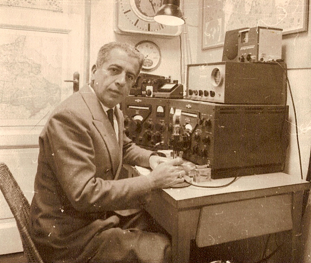
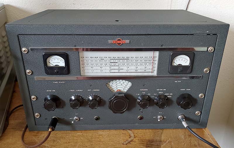
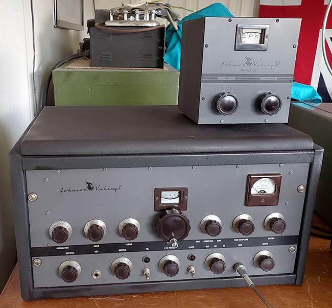
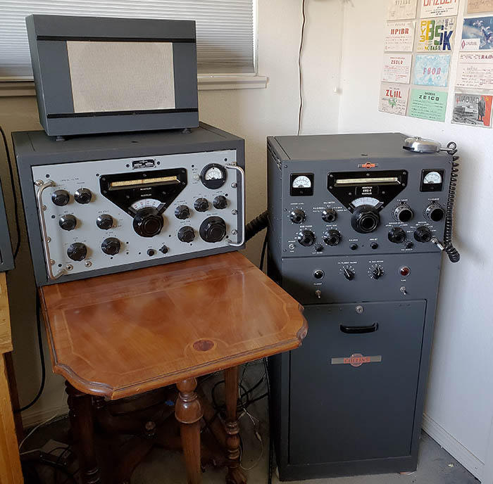
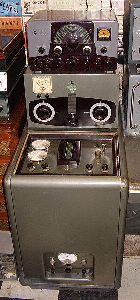
Art Collins and the Air Force in the mid-fifties. I've had sn: 616 set-up with a Collins Lab 51J-4 sn: 4723 as shown in the photo above. The KWS-1 is certainly one of the best from the "Golden Age of Ham Radio."

OPERATIONAL NOTES: AM on the KWS-1 is not without headaches - mostly in the form of "Critical Audio Reports" from the BC-audio crowd. The KWS-1 will NEVER sound like double-sideband AM and it will NEVER sound like high fidelity AM. No matter how many times you describe the KWS-1's method of generating an AM signal and the fact that it's a "single sideband signal with reinserted carrier" you'll still run into those listeners that expect AM BC Collins 20V-quality audio from anything built by Collins - I don't know why,...most of Collins' equipment was for communications. However, a few things performed during AM set-up can avoid most "Critical Audio Reports" when using the KWS-1. Be sure to run the carrier reinsertion (Carrier Level) so that it results in about one-quarter output power as compared to full power output. This is usually about 150 watts of carrier and is usually achieved at about 250mA of PA current. Use an inline watt meter to be sure of the carrier power output. Typical full power output DC on a KWS-1 will be around 625 watts so one-quarter would be around 150 watts. Be sure to run the Audio Gain very low - usually about 1 or so - and NEVER use the ALC - always keep the ALC at full CCW in the AM mode. Be sure to monitor the PA Grid current - it should never move from 0. Any grid current flowing will create distortion. Even a minor fluctuation of the Grid Current meter needle is indicating non-linearity and resulting distortion. Keep the Audio Gain low (around 1) and avoid excited, over-animated voice levels (if possible.) Use an oscilloscope to monitor your modulation and watch the Grid Current constantly. Following these suggestions will have your KWS-1 producing "its type of AM" about as well as it can. You'll still get "Critical Audio Reports" and sometimes you'll just have to tell the "reporter" that the KWS-1 wasn't designed as a plate modulated AM transmitter. It wasn't designed as an AM broadcast transmitter. It's a high-power SSB transmitter that can do AM in a method that produces "communications quality" audio with a narrow bandwidth and THAT was what was important for hams (and some limited military use) in the 1950s.

One other thing on the Collins procedure for setting up for AM operation,...Collins really thought that nobody was going to operate AM at one-quarter power when they could operate full-power CW or SSB. So, their AM set-up is sort of "try and see" how it will work. Basically, Collins has you set-up for full power match to the antenna with the Carrier Level producing about mid-scale grid current and PA current at 500mA. Then switch to AM and reduce the Carrier Level to show 250mA and set the Audio Gain as required. The problem is how the antenna load reacts to different carrier wave envelopes that are produced at about 650 watts DC and 150 watts DC. I've found the mismatch is noticeable and the efficiency is greatly reduced at low power. What I do is to follow the Collins set-up but at the point where I've reduced the Carrier Level for 250ma of PA current, I then readjust the PA Tuning for the correct "dip" and then I might adjust the PA Loading slightly and "re-dip" for the best antenna match. I've found that with the approach of "retuning" after the reduction of carrier injection the KWS-1 PA current is very stable and rarely needs to be adjusted after setting it lower, to about 230mA. I actually have to reduce the PA current (Carrier Level) for best ratio of Audio modulation to Carrier Level. This results in an increase in output power to about 175 watts with with a reduction in PA current to 230mA, in other words, better efficiency. Also, much better stability and the audio modulation is very high with no grid current showing.

More complaints are to be expected in modes other than AM. Especially nowadays when the majority of hams are using modern transceivers and expect absolutely no drift. The KWS-1 will drift. In the 1950s through the early 1970s, the slight <1kc drift that the KWS-1 exhibits during a QSO was not considered a problem because every ham used separate receiver-transmitter setups and a slight retuning of the receiver was normal operating procedure. Besides, the KWS-1's <1kc drift was so much better than most other rigs. But, today any frequency drift is unacceptable and you're likely to receive a "critical frequency stability" report when operating some modes. Some KWS-1 users will employ a synthesizer as an external VFO or use a DSO device at the EXT. VFO input to keep the KWS-1 at "zero drift." The only mode where the "stock f drift" isn't noticed is on AM. SSB will garner complaints and RTTY using a stock KWS-1 is impossible anymore (in the 1970s, I ran this KWS-1 at reduced power doing "real machine" RTTY with no problems. Not anymore! An attempt at RTTY in 2022 was a disaster because of the "zero drift" necessity when communicating with modern transceivers that have built-in RTTY mode. Nowadays, when operating RTTY, a drift of 20 or 30 hertz will put your FSK signal out of the filter's bandwidth, so very little drift can be tolerated in the RTTY mode anymore. Older RTTY TUs were more forgiving and many military TUs worked on one audio frequency and any deviation was part of the Baudot code being sent, so drift wasn't too much of an issue.) CW QSOs are so short with very short exchanges that the KWS-1 doesn't have time to drift much. Most users believe that excessive heat from the PA box being so near the PTO is the cause of the f drift. Modifications include fans and adding insulation on the exterior of the PA box near the PTO. However, the use of an external modern synthesizer device connected to the EXT. VFO input is the easiest solution and it is non-invasive. 


E. F. Johnson Company -  Viking Desk Kilowatt, Viking Ranger, Viking KW Match Box

The Viking Desk KW was introduced in 1955 and was available up to around 1964. The "Desk" is a high power RF amplifier with a high power audio modulator, power supplies and all of the control equipment built into a fairly compact "pedestal." The Desk KW features continuous tuning from 3.5 to 30mc. The PA operates Class C and has two output levels, low power for tuning up or operation at 250 watts carrier output or high power for 1KW input power. Plate voltage is either 1300vdc or 2600vdc depending on the output power selection. Originally, 872 MV rectifiers were used for the Plate supply but many amateurs have replaced these with 4B32 Xenon rectifiers or with Solid State rectifiers. An external relay (operated by the exciter) must be used with the Desk KW for linear operation for SSB to allow switching between "Blocking Bias" and "Operating Bias." The PA requires 30 watts of drive for full output and the modulator requires 15W for full audio drive on AM. The PA tubes are a pair of 4-250A tubes (4-400 on later Desks) modulated by a pair of 810 tubes. The entire unit is on guides and rollers and is easily accessed for testing or adjustments. The desk itself was a $123.50 option that could be bolted to the side of the pedestal for complete operating station desk with room for the exciter and the station receiver. The Desk KW sold $1595 without the desk. The Desk KW shown is number 280 of the 402 built.

The Viking Ranger was a 75 watt CW or 65 watt AM exciter-transmitter that covered 160M to 10M and had a built-in VFO that was very stable. The audio section featured a special modulation transformer with a winding that was used for negative feedback resulting in excellent quality audio. The PA tube is a single 6146 and the modulator tubes are a pair of 1614 tubes. The Ranger had all of the outputs accessible to interface with the Desk KW for sufficient drive for full output from the Desk KW. Generally a small attenuator is inserted between the Ranger RF output and the Desk KW input to allow better adjustment of the Ranger's drive and output circuits. Rangers were very popular as a stand-alone transmitter also, especially for Novices since the power limit then was 75W on CW only, crystal control (you got to use the VFO after you up-graded your license.) Still today, the Ranger is a popular transmitter for vintage AM because of its excellent audio and "bullet-proof" construction. Over 14,000 Rangers were built. They were available as either a kit or fully assembled. Prices were $293 assembled or $214.50 as a kit. The later version was designated as the Ranger II and featured different modulator tubes, a two-tone gray paint job and dropping the 11M coverage in favor of 6M coverage.

The Viking Match Box was a heavy duty, balanced antenna coupler that was link coupled, used bandswitching and had two split-stator variable capacitors that allowed matching various kinds of antenna loads to a transmitter. The Match Box was specifically designed for balanced antennas but could also match coax fed loads or end fed wires. The SWR bridge required an external Directional Coupler to function but the Match Box was available without the SWR bridge option in which case there is no meter installed. A built-in antenna relay is included inside the box with access via an external terminal strip mounted on the rear of the unit.

The Viking Desk KW shown was partially disassembled and was going to be "parted out" by the University of Nevada (in 1997.) A friend of mine that worked at UNR saw the Desk KW (disassembled) in the hall on the second floor of the Electronics Building. His phone call to me was something like,... "you interested in a Johnson Desk KW? Well you better get over here, they're throwing one away!" When I got to the Electronics Building, I found the Desk KW apart and looking like it was destined for destruction. I asked around and finally found that the Wolf Pack Ham Club had gotten the Desk as a donation and they weren't sure what to do with it since they couldn't move it to the third floor where their ham club station was. I made a deal with them of cash for some equipment they wanted to buy and then the Desk KW was on its way to Virginia City. The KW Matchbox was included in the deal. I rebuilt the Desk KW and it is now fully operational and usually on the air on the Saturday Morning West Coast AM 75M Net, 8AM Pacific Time, 3870 KC (not anymore. After two decades of providing AM operating hams an opportunity to be on the air without the QRM of nighttime operation, two California SSB hams decided they would "take over" 3870kc at 8AM Saturday mornings. Deliberate high power SSB QRM was endured for a few weekends and then the futility of the situation was realized and the 3870 AM net was shutdown for good. Last time I checked, those two California hams are no longer using the frequency, which is to be expected since it was deliberate sabotage of the Sat Morn AM Net.) The Viking Ranger was the XYLs Novice transmitter back in 1975. We've always kept it in operational condition. Several years ago I replaced all of the aging capacitors. Other than increasing the wattage rating of the regulator resistor (but not changing its proper location in the VFO) no mods are installed  - Rangers sound very nice with stock audio and changing the value of the coupling capacitors just ruins the audio. The microphone grid input resistor is purposely a very low value to reduce bass response and this resistor can be changed to some value greater than 1 meg ohm for better bass response without changing the coupling capacitors (4.7meg is ideal.)

Inside the Viking Desk KW - The Desk KW is the type of transmitter that is going to require maintenance from time to time. The most common annoyances will be located in the Potter-Brumfield relays since their contacts always seem to need attention after a year or two of operation. It's pretty easy to access the relays since they are located in the front of the two-tier chassis. Clean the contacts with 400 grit Alu-Ox paper and do the final clean with De-Oxit on a piece of paper pulled through the contacts. These contacts are always pitted so don't worry about the 400 grit paper damaging the contacts - they are already damaged.

One of the main problems with the Desk KW is that it was wired with solid conductor wire which has a real tendency to break when moved. Of course, Johnson thought you'd never be moving the harness around but you have to when going through the transmitter. Keep an eye on the wires while doing any rework as you're sure to break at least one wire during the process.

The four fans used in the Desk KW are also problems. The two main fans "push and pull" the air through the Desk chassis to keep everything cool. These open frame fans don't last forever and many have been replaced over the years. There are exact duplicates of the fan motors still available and many suppliers stock them. Reuse the original fan blade and be sure that you have the lower fan pushing air in and the upper fan blowing air out. The originals should be serviced every year or so. Oil the felts by saturation with light machine oil.

If you're using a Ranger to drive the Desk KW, you'll be plugging the Ranger into the AC socket that is provided at the rear of the Desk chassis. If you have the Ranger's AC plug oriented one way, the relay drive to the Desk works. Oriented the other way, the Desk relays won't work. Once you've determined which way is correct, paint the upper part of the Ranger's AC plug with red paint. That way, in the future, you'll always know which way to plug-in the Ranger.   >>>
>>> I had to replace the two toggle switches on this Desk KW. The originals are rated at 3A at 125vac - a pretty hefty switch - but they became intermittent after 50 years of use. I replaced them with 10A 125vac toggle switches. For the AC power switch (SPST) this is no problem since there's plenty of room. For the meter selection switch though I had to modify the switch terminals by cutting them down as low as possible. Then I drilled a 1/16" hole in each shortened terminals for the wires to mount into. Also, the switch has to be mounted as far forward as possible. Because the switch is in front of the meter terminal board and both are located in the shielded meter box, there isn't much room for a large toggle switch but with slight modification, it all fits together.

The Desk KW chassis rolls out but only so far until you are going to have to support the front. I use a $12 dolly that you can find at Home Depot or many other hardware stores. The dolly is placed under the Desk chassis and as you pull the chassis out you move the dolly more to the center of the chassis until the chassis is entirely out of the pedestal. Then you'll have a way to roll the chassis around for easy access to all areas. The chassis weighs close to 200 lbs with all of the iron installed, so the dolly helps a lot. When re-installing the chassis into the pedestal, I use a lever (a five foot long piece of 3/4" pipe) to lift each back edge of the chassis into the pedestal. Once both edges are in, then it's easy to push the chassis back in on the internal rollers.

I use 6156 tubes in the final PA because these RCA versions of the Eimac 4-250A are usually cheaper but have the same specs. The only difference is the 6156 doesn't have the metal base shroud to direct air flow around the tube. Since we only run the Desk KW in the "Tune Mode" it is never really running more than at just "an idle" and therefore the 6156s work fine. I also don't use the original 872 MV rectifier tubes but use 4B32 Xenon rectifier tubes.


E. F. Johnson Company - Viking Navigator
 

The E. F. Johnson Company has been in business since the 1920s and is still active in the component business. During the post-WWII period up to about 1974, Johnson was a major builder of ham transmitters, ham accessories and other communications equipment. The Viking Navigator was introduced in 1957 and was available for about four years. It could be purchased as either a kit or fully assembled. The transmitter-exciter is only 40 watts input power with a little over 25 watts of output power on CW only. Coverage is 160 meters through 10 meters. The PA tube is a 6146 with about 400vdc on the plate.

 
The Navigator featured a fairly standard Johnson VFO, although regulation is somewhat different than their standard VFO as found on the Ranger, for example. Also, a keyer tube is used which provides adjustability of the CW keyed waveform shape. The keyer circuit is also quite different from the Ranger. The "Iron Vane" meter is a source of many problems and its accuracy is always in question. The slide switch that selects Grid or Plate current is also somewhat problematic. Many times, Navigators are found with these two parts replaced. A great QRP CW transmitter that is very small and light weight. Original selling price was $199.50 factory-wired and $149.50 as a kit. Only 840 Navigator transmitters were produced. The Navigator was donated to the museum by K6QY.
 

Photo left shows the Navigator with the stock iron vane meter and stock "Grid-Plate" slide-switch.

Just How Bad is the Original Navigator Meter? - Absolutely Awful. When operating a Navigator as a CW QRP transmitter, the "Iron Vane" meter is constantly "banging" against the zero-stop. Sooner or later, this must have resulted in the meter needle breaking off and ruining the meter. Also, switching transients sometimes caused the coil to "open." That's probably why nowadays so many Navigators have replacement meters. It's very easy to install a jumper across an original meter's terminals to protect the meter and then use an external watt meter to load up the transmitter. A defective original Navigator meter will be next to impossible to replace so this easy protection assures a functional original meter will survive indefinitely (well,...maybe.)

I can't stress the point strongly enough that the original Johnson Navigator "iron vane" meter is a real "piece of junk" and is not really repairable if a problem develops in an original unit (who'd want to fix it anyway.) The plastic cover is glued all around the perimeter of the meter scale backing plate and any attempt to cut away the glue cracks or breaks the plastic cover. Apparently, if a problem developed in the meter, Johnson wanted you to replace the entire meter instead of repairing it. That might have been okay in the late 1950s but now, 60+ years later, I don't think Johnson still stocks Navigator meters. Johnson's decision to install a $2 meter into a $200 (factory-wired price) transmitter was certainly profit-motivated. However, it is possible to fit a Johnson Ranger meter into the Navigator and with some minor adjustments to the shunt(s) it becomes an accurate and useable instrument (which the original Navigator meter never was.) Here's how it's accomplished (after you've found a Viking Ranger meter, of course.

The Johnson Viking Navigator "DeLuxe"

Installing a Viking Ranger Meter into the Navigator - In 2016 I got the chance to actually do something about the original "El Cheap-o" meter used in the Navigator. I was able to obtain a Viking Ranger meter from a junk Ranger that was being "parted out." I tested the meter, which was in very nice cosmetic condition, to see if it was usable electrically. The Ranger meter is a ~5mA FS unit that is a d'Arsonval rotating-coil meter. This design is far more accurate than the crude "iron vane" meter that relies on magnetic attraction of a "vane" to move the meter pointer. A quick test is to just measure the DCR of the meter coil. In this case it measured ~20 ohms. A more accurate test is to actually measure how much current is required for a full scale indication. An adjustable low-level dc voltage is connected in series with a 1K ohm resistor, a current meter and the meter under test. The dc voltage is adjusted until the meter under test shows a full scale indication. The current meter will now show how much current is needed for full scale deflection on the meter under test. In this case, it is 4.5mA. Linearity can also be checked at half-scale, in this meter it was 2.2mA. 

Something Interesting with the Original Meter - I hadn't operated the Viking Navigator since I had moved from Virginia City in 2012. The Navigator had been in storage in the upstairs lab which is a stable environment with no extremes of any sort. In my research before actually performing the Ranger meter installation, I thought I'd test the original iron-vane meter. A measurement of the coil showed no continuity at the terminals. I had run into this problem once before when I first got the Navigator. At that time, loosening the terminal nuts and retightening them got the meter functional. This time, no amount of loosening and tightening helped. The meter coil was disconnected from the terminals. There is no repairing the original meter. It can't be taken apart since the plastic cover is glued to the back and any stress on the plastic results in cracks. Better to leave the original meter in good cosmetic condition albeit non-functional since I was planning on installing the Ranger meter anyway.  >>>

The Installation Plan - One can't just remove the old Navigator meter and bolt-in the Ranger meter. These are two different types of meters that have different FS indications and FS current requirements. This will require re-calculating the shunt values needed for the Ranger meter to accurately read PA grid current and PA plate current in the Navigator.

Additionally, the Ranger meter isn't exactly a perfect replacement fit. The original Navigator meter requires a 2" diameter hole while the Ranger meter requires a 2.187" hole. The original Navigator meter was mounted using a bracket that attached to the back of the meter and pushed against the back of the front panel to hold the meter secure. The Ranger meter mounts conventionally using four studs that use 4-40 nuts and washers to secure the meter to the panel. This means some modification to the front panel is necessary. Fortunately, if for some reason the original Navigator meter was to be re-installed, the modified larger clearance hole and the four mounting holes are covered up by the overall size of the original meter.

Originality versus Cool Functionality - Anyone who reads any of my articles knows I'm a serious advocate for strict originality. How could I actually want to modify a rarely encountered transmitter to the point where I'd actually be "cutting and hacking?" It seemed unthinkable! However, that's just how BAD the original Navigator meter is. I would think that the E. F. Johnson decision to use the iron-vane meter was based on keeping costs low so the Navigator would be reasonably priced (it really wasn't.) If Johnson could have put another $15 to $20 into the cost, they would have used the Ranger meter. The Ranger meter is a genuine, contemporary to the Navigator, "Johnson" part and it even has the Viking head on the scale. Additionally, it is an illuminated meter (the original iron vane meter isn't.) So, my argument for performing this modification is "Johnson would have liked to have built the Navigator this way but it would have cost a lot more and sales would have been even less than they already were!"  Maybe Johnson should have offered this version as the "Navigator DeLuxe."  

Before Cutting the Sheet Metal,...Test - Always a good idea. Make sure your modifications are actually going to function correctly. In this case, the modification was to the shunts used in the Navigator. We don't really need to know what the original iron vane meter required since it was now non-functional. So, if your Navigator has a bad original meter or some sort of replacement meter and you want to install a Viking Ranger meter, you'll need to calculate the shunts. Normally, you can use the formula of R shunt=R coil/n-1 where n=change in scaling. In the case of the Ip our FS is 200mA and the FS meter movement is 5mA so n=200/5 or 40, so n-1=39. The formula then is R shunt=20/39 or ~0.5ohms. An accurate digital current and ohm meter that will read low value ohms and milliamperes accurately helps in final accuracy of the shunt calculation and resistor selection.

I did a quick test for the grid current using 10mA FS with R shunt=20/4 or ~ 5 ohms. I installed a 5.1 ohm resistor for the grid current shunt. Although the original meter didn't require a shunt, the Meter switch has an extra unused pin (pin 9) that can be used for a grid current shunt resistor connection into the circuit.

During testing I wanted to double-check the accuracy of the Ranger meter and the shunts. I did this by using an accurate current meter installed directly into the grid circuit. I adjusted the Navigator to show 4mA of grid current. I then connected the Ranger meter which showed 2.5mA. A slightly higher shunt resistance was needed so I installed a 6.8 ohm resistor and this then allowed the Ranger meter to show 4mA. I did the same with the plate current shunt and ended up with 1.0 ohm, 1.2 ohm and 1.5 ohm resistors in parallel, or about 0.27 ohms, for an accurately reading plate current meter.

As to why the actual shunt values were slightly different from the calculated values was probably due to the meter I used to measure the Ranger meter coil resistance. I really needed a digital meter that was capable of measuring "very low ohms" accurately which I didn't have. Also, the actual FS current for the meter was 4.5mA and I used 5.0mA in the calculations. With these two changes my calculations would have been accurate. As it was, I got close and then "trimmed" the values to have the Ranger meter read accurately by comparison with a known accurate current meter.  >>>

Sheet Metal Work - Now that we had the Ranger meter working with the Navigator we had to actually modify the front panel so that the Ranger meter would fit and could be mounted. Trying to do sheet metal work with the panel mounted to the chassis will result in difficulty getting an accurate fit. It's better to entirely remove the front panel so you can rework the meter hole neatly and drill the four mounting holes precisely. There are many ways to enlarge the meter hole but since we were only removing 3/32" around the perimeter of the hole, I carefully used a nibbling tool and then finished with a fine round file. The mounting holes were drilled. See photo below for the appearance of this "hand fitting" job.

Mounting the Meter - When mounted in the Ranger, the meter had a full metal rear cover that provided shielding and mounting for the chokes, bypass capacitors and lamp socket mounting. The meter cover mounted via the two meter studs using various insulator washers and nuts. The meter itself mounts to the front panel using the four studs with lock washers and nuts. Then the meter cover shield mounts to the meter studs and has its flex fingers pushed against the inside of the front panel to provide a chassis ground connection. The lamp socket "snaps" into the hole provided and this has the lamp placed the proper distance from the meter scale for full illumination.

Meter Cover Shield Modification - To install the rear meter cover in the Navigator requires a clearance hole be cut in the bottom of the cover. This is necessary because of the proximity of the Grid-Plate slide switch (directly below the meter.) The opening width has to be 1.75" and the depth is 1.125" and this is easily cut using a hack saw and then dressing the edges with a file. If carefully executed, the opening looks stock. Mounting the cover requires an insulating washer on the inside and on the outside of each stud. I used the type of insulating washer that has a molded shoulder that provides insulation of the stud through the hole in the cover. See photo to the right.

Connecting the Meter - Each meter connection is filtered with a choke and bypass capacitor. The 6.3vac to the meter lamp is also through a choke and bypass capacitor. The meter studs have terminal solder lugs and the wires from these connect directly to the Grid-Plate slide switch. The meter lamp choke filter is connected to the 6.3vac dial lamp buss connection. The finished Johnson Ranger meter installation is shown in the photo to the right.

Keying Adjustment - R-9 adjusts the keying circuit to produce a "shaped" wave envelope that has a somewhat slow start and finish to the pattern. This reduces "clicks" that are sometimes heard with CW transmitters. The procedure is to adjust R-9 for full "on" keying and then adjust in the opposite direction until the keying just turns "off." Then continue slightly past the turn "off" position. A little vague. I adjusted by listening to the keying with the Navigator on the dummy load and listening on a R-390A receiver. I found the best sounding keying was actually quite a bit farther into the pot rotation rather than just "slightly." I found the keying tended to "bloop" if R-9 wasn't adjusted quite a bit past the "off" position.

Panel Mounting Screws - Since the cabinet for the Navigator is made out of aluminum it's pretty easy to strip the threaded holes when mounting the Navigator chassis and panel into the cabinet. But, since the cabinet is aluminum is fairly easy to recondition the threaded holes to have enough material to allow gentle tightening of the panel screws. The holes can be deformed using a tool to compress the hole edge material  The compression will slightly reduce the size of the hole. A small vise grip type of tool can usually deform the aluminum enough. Then a 6-32 tap can "chase" the threads or self-tapping screws can be installed. In either case, don't over-torque the screws, just barely tight will work fine.

Operation - Testing into a dummy load plus a Drake W-4 wattmeter showed that I could load the Navigator to about 25 watts maximum output power. The Navigator was rated at 40 watts input power so the 25 watts equates to about 62.5% efficiency which is about right for Class C PA operation at the plate voltage the 6146 is provided with (around +400vdc.) On CW, 25 watts output power is sufficient for communications provided a decent antenna is used. I used a 135' center-fed inverted-vee fed with 94' of ladder line. When used on 40M this antenna becomes "two half-waves in-phase" and begins to exhibit a little gain - not much,...maybe 0.5db over a regular dipole. I selected 40M so I could do my test QSO during the day. Although there isn't a tremendous amount of activity on 40M CW during the day, there isn't any QRM either. The interesting thing was that, even then, I managed to work everyone that was a "daytime 40M CW op" in about three days (and that was in just three QSOs!)


Photo left shows the "Navigator DeLuxe" with the Johnson Viking Ranger meter installed. The top scale is 0 to 200mA and used for plate current. The 0-5-10 middle scale is used for 0 to 10mA grid current.


Eldico Electronics  -  SSB-100-F


Eldico Electronics was formed by Donald J.S. Merton in the late-1940s. Originally the business was called "Surplus Radio Inc." but the name was changed early-on. Merton's ham-call was K2AAA but earlier he held the calls W2UOL and W9ROI. The company was first located in Douglaston, L.I., NY and Eldico Electronics had a factory at 29-01 Borden Ave. in Long Island City, L.I., NY. The company produced mostly ham transmitters. Eldico later became a subsidiary of Radio Engineering Labs (REL) of Long Island City, NY.

Eldico is mainly known for the Collins S-line "clones" they built around 1960. These initially were part of a military second-source contract between Eldico and the Air Force, however Eldico then decided to also sell the "clones" directly to the general public. That Eldico was using the S-line clones to apparently compete with Collins upset that company, who then pressured Eldico to stop production of the clones. However many examples were sold and they are still relatively easy to find. Supposedly, the designer of the Collins 75S-3 was also the designer of the Eldico R-104 (urban legend?)

The SSB-100-F came out in 1957. It was a balanced modulator-crystal filter ssb supression type transmitter that used 5894 in the final PA. The transmitter covered 80M thru 10M with 10M covered in three individual bands. 11M was also covered since the SSB-100-F was a pre-CB era rig. The circuit uses 22 tubes including a 1CP1 1" diameter CRT that is used to provide a trapezoid pattern for monitoring transmitted audio quality. The SSB-100F was rated at 100 watts PEP input power in SSB, 50 watts input power on CW and 25 watts SSB-AM. Only one sideband could be transmitted in the AM mode. Carrier was reinserted post-filter to accomplish a SSB-AM signal. VOX or Manual operation was provided but not PTT.

Not too many SSB-100-F were produced. Priced at $795, it's not surprising that sales were slow. Estimates are around 300 to 500 units were produced. The SSB-100-F shown is serial number 0067. I also have a "parts set" SSB-100F with the serial number 0079. Eldico also produced a SSB-100MIL version that provided 12 crystal-controlled selectable channels besides a VFO. Eldico also produced a linear amplifier, the SSB-1000.


Eldico SSB-100F  SN: 0067  ca: 1958


DCS-500 - Homebrew Double-Conversion Superhet Receiver

From the 1962 Handbook up to the 1964 Handbook, the "top of the line" homebrew receiver project was the "DCS-500." This was a formidable project for the homebrewer consisting of a 12 tube plus two transistor, double conversion superhet that had an impressive layout and appearance that was sure to also have a dominating bench presence if the project was successfully completed. The receiver used plug-in coils to eliminate complicated bandswitching and reduce losses that might otherwise be encountered with having all of the coils present under the chassis. The plug-in coil design simplified a portion of what was already a fairly complex receiver. The first conversion was at a fairly high frequency of 4500kc while the second conversion was very low at 50kc. The very low 50kc IF was popular in the 1960s as it provided excellent selectivity. J.W. Miller TV coils were slightly modified and used for the IF transformers and BFO. The 4500kc IF had its bandwidth determined by a four crystal IF filter that utilized surplus FT-243 crystals. The second conversion oscillator also used a surplus FT-243 crystal operating at 4495kc. Four positions of selectivity were part of the circuit with the bandwidth determined by fixed capacitors. The detector was a standard envelope (diode) detector but the BFO injection was robust so SSB signals could be demodulated easily. AGC, Noise Limiter, BFO, Crystal Calibrator (where the two transistors were used) Antenna Trimmer and a S-meter were all features of the DCS-500. Audio output was either a headset using the phones jack on the front panel or 3.2Z ohm loudspeaker using terminals on the rear chassis. Other features available on the rear of the chassis were remote standby, 50kc IF output, accessory B+ output and the 3.2Z ohm speaker terminals. The project in the Handbook shows the receiver built with many National Company parts, J.W. Miller coils and a large Bud Industries cabinet. The build-concept was to use easy-to-obtain parts (at the time they were easy to obtain,...not now.) Almost everything could be ordered from any of the large catalog suppliers like Allied, B-A or Lafayette. This DCS-500 was constructed using almost all of the recommended manufacturer parts and therefore is very close in appearance to the project receiver shown in the ARRL HB.

Most likely, if the DCS-500 was going to be constructed, the homebrewer probably was experienced in electronic construction techniques and probably was a competent sheet metal worker. Many electronic "kits" or less complicated homebrew projects were often built by beginners with no electronic assembly experience. A close inspection of the soldering quality is generally a clue that indicates the level of experience of the builder. Overall this DCS-500 receiver looked like a very talented and experienced builder had performed the construction. However, appearance and functionality don't necessarily relate to each other.

As found, this DCS-500 was non-functional. It was in very good cosmetic condition although very dirty and obviously contaminated with some kind of white residue that adhered to mostly the plastic items. I didn't have the correct year ARRL HB, so my first task was to find a 1963 HB (and that was easily and quickly found on eBay.) I decided to go ahead and do the preliminaries before any documentation arrived. One shorted 6U8A tube was found with all other tubes checking out in good condition. The power supply filter capacitor was reformed but, although not shorted, it didn't filter very well either. A couple of "piggy-backed" electrolytics got the hum down enough to proceed. Starting at the audio circuitry, I had output with a 400hz signal injected to the grid of the 6AQ5. I injected a modulated 50kc signal at the grids of the IF amplifier tubes and also had audio through to the speaker. Injecting a 4500kc signal into the Mixer stage also produced a speaker response but nothing could be heard with the signal generator connected to the antenna.

Further testing showed that the first conversion oscillator wasn't functional. I checked the oscillator plug-in coil and noticed that the trimmer capacitor (air variable) was shorted. The type of trimmer used the hex collar to secure the rotor shaft. The hex collar had come loose and dropped the rotor and that was shorting the trimmer. I repaired the hex collar (sweat soldered the hex collar in position) and now the oscillator seemed to be somewhat functional. There now was "tunable" noise although not anything like 40M signals. At this point, my 1963 HB was going to be delivered the next day, so I stopped troubleshooting since more information in the form of the schematic and the HB write-up would be immensely helpful. By this time, I had discovered that the Crystal Calibrator had never been functional since there was no connection to the chassis. I had also discovered two unsoldered joints, one on the first conversion oscillator coil pin and one on the antenna coil pin. Although the soldering looked fine as far as quality, more problems were discovered as troubleshooting proceeded.

It was beginning to look like this DCS-500 was never totally completed and, positively, it was never functional. The lack of any dial frequency nomenclature was one clue that no calibration took place. The lack of a chassis connection for the 100kc calibration oscillator was another indication. Once I got the receiver somewhat functional, I found that it had never been aligned. The 50kc IF was resonate at around 55kc which was probably where the slugs were set from J.W.Miller. The S-meter was wired backwards. The Audio Gain control didn't have a connection to chassis and ran "full on" until corrected. Although the dial tuning was loaded with "birdies" it did tune in a couple of SW BC stations - only they were around 9.3mc rather than 7.3mc. This problem was caused by the LO coil being wired incorrectly inside the coil form. The non-functional BFO was caused by the BFO coil being wired with the grid side being connected to the rotor of the BFO tuning condenser that was also physically connected to chassis. Rewiring the tuning condenser corrected the problem and got the BFO working. The second 4500kc IF coil (L5) wouldn't adjust. This problem was caused by a "never installed" wire that connected the B+ side of L5 to the crystals. Noisy operation of the 4500kc IF was caused by an unsoldered bypass capacitor. Finding each of these problems resulted in the DCS-500 working better and better with many 40M signals now being received.  

This DCS-500 only had one set of coils with it,...the ones that were installed. They were for 40M. Tracking is set at the high end of the band with the LO and Mixer trimmers. The low end "spread" is set by "pushing turns" on the coils. Each set of coils would be different and dependent on how the coil was wound by the builder. I had to "push" the LO winds closer together to get the 40M band to track from 7.0mc = 10 on the dial to 7.3mc = 90 on the dial. This allows a little tuning above and below the ham band for checking other types of signals. I checked my junk boxes and found two blank polystyrene coil forms, a four pin and a five pin. I needed one more five pin. A short while later, I found a couple of 80M coils for the DCS-500 at "Ham & Hi Fi" in Sparks, Nevada. I still have to wind the Antenna coil for 80M. If more of the clear polystyrene coil forms are found, I would then next wind a set for 20M. When I have the 40M and the 80M coil sets complete, I'll add calibration to the National tuning dial. 

Improvements to the DCS-500 could be some additional shielding and better filtering on the power supply. A bottom cover would probably help a lot. If the receiver is installed in a cabinet then the chassis should be bolted to the cabinet so that it provides the bottom shielding. An extra filter choke and filter capacitor would be a big help for the hum level which is fairly high if the receiver is operated with the AVC off, AF gain high and riding the RF gain for best SSB and CW reception. This set-up does result in noticeable hum. The DCS-500 can be operated with the AVC on when in CW or SSB, but, receiving in poor conditions is improved with the manual gain set up with AVC off. The HB article recommended an angle aluminum extrusion be mounted to the top of the chassis to "stiffen" it. This particular DCS-500 doesn't have that installed but I think it would help to improve stability if it were installed.


1. "Communications Receivers - The Vacuum Tube Era, 1932-1981"  by Raymond S. Moore - Undoubtedly the best reference book on tube-type superheterodyne communications receivers. History of receivers and the companies along with circuit description and photos of each receiver. Four editions have been printed.

2. "Shortwave Receivers Past & Present - Communications Receivers 1942-1997"  by Fred Osterman - Excellent reference book on later communications receivers. Includes many foreign makes. Circuit descriptions, photos, prices. There is a new, expanded edition now available (2016.)

3. QST, Radio News and Shortwave Craft magazines from 1945 up to 1960s - These vintage magazines are excellent sources for contemporary reviews of equipment and pre-production articles by the designers. Advertisements are invaluable for dating and development of the model line.

4. Operator's Instructions, Factory Manuals, Rider's Troubleshooting Manuals - Original manuals are excellent sources for circuit descriptions, design intentions and performance expectations. Many times the same information is included in the appropriate Rider's Troubleshooting Manual.


Return to Home/Index


Radio Boulevard
Western Historic Radio Museum

 Vintage Radio Communication Equipment Rebuilding & Restoration Articles,

 Vintage Radio History and WHRM Radio Photo Galleries

1909 - 1969

- 60 years of Radio Technology -


This website created and maintained by: Henry Rogers - Radio Boulevard, Western Historic Radio Museum © 1997/2023