Radio Boulevard
Western Historic Radio Museum


Patterson Radio Company

PR-10 "All Wave" Communication Receiver
PR-10 Pre-selector

LA Radio Mfg'ers History, Patterson Radio Co. History, PR-10 Details,
Pre-selector Details, Serial Number Analysis, Restoration Details,
Competition Comparisons, Expected Performance Details


by: Henry Rogers WA7YBS-WHRM

The Patterson PR-10 was a "Los Angeles-built," superheterodyne communication receiver that was produced early enough to have many unique or, at least, unusual design features. Some of these features became "standards" for communications receivers while others are only found on the PR-10 and its matching Pre-Selector. Besides its unusual design, the PR-10 has an important place in history relating to radio manufacturing on the West Coast in the 1930s. The PR-10 has always been a favorite of mine, probably because it was the first communication receiver I owned (second-hand, of course,...I was age fifteen at the time.) This write-up includes circuit details, restoration suggestions and a performance report.  -  H.Rogers Mar 2016  

Patterson Radio Company


Why Were Patterson Radios Built at Gilfillan Bros.,Inc. in Los Angeles?

A Brief History of Los Angeles Radio Building in the 1930s

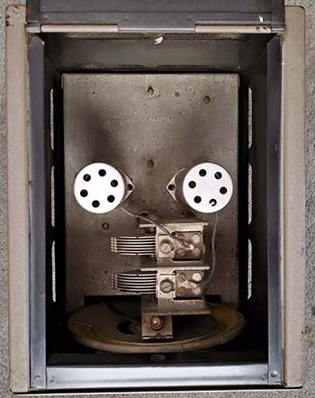
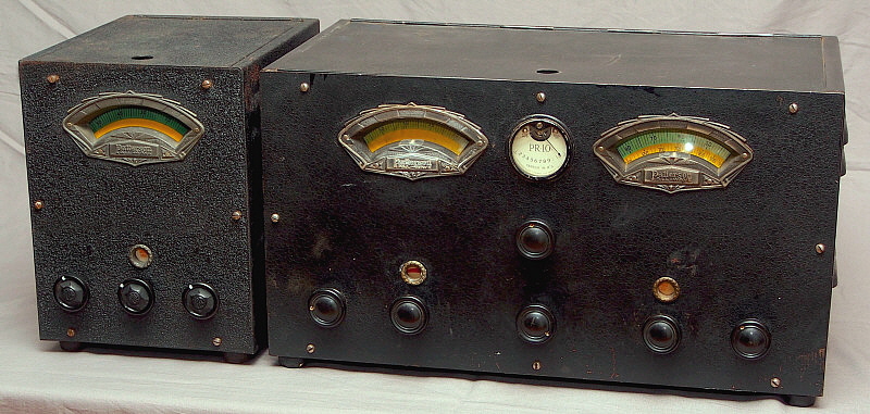
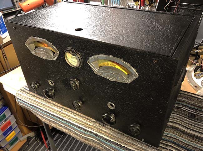
To understand why Patterson Radio Company built the PR-10 at the Gilfillan Bros.,Inc. plant in Southern California, requires some familiarity with Los Angeles radio manufacturing history.

Before 1927, radio building on the West Coast was uninhibited and pretty much any type of radio could be built and sold without very much interference from the license-holding and patent-owning radio manufacturers located on the East Coast. California was just too far away and their share of the booming radio market didn't seem to impact the radio-selling profits enough to enlist infringement-busting lawyers to pursue those who were violating patents.

By 1927, RCA was beginning to assert some control over some of their newly acquired patents. Mainly the "Tuned Radio Frequency" circuit (not the Neutrodyne configuration though, that belonged to the Independent Radio Manufacturers) was important at the time although anything resembling a superheterodyne was almost certain to be a target for the radio lawyers, too. Although RCA didn't own the superhet-patent (Westinghouse did,) they handled most of the legal actions because of their cross-licensing with the members of the so-called "Radio Group," consisting of General Electric, at the head, with Westinghouse and AT&T (former member United Fruit Company had sold their radio holdings to RCA around 1924.)

RCA was beginning to pressure the Gilfillan Bros.,Inc. (Sennett and Jay Gilfillan,) the only large-scale radio builder in Los Angeles (actually in the entire West) who also had other assembly plants around the country. The pressure became intense enough that eventually Sennett Gilfillan got on a train heading East with the intention of a "face to face" meeting with RCA officials.

Arriving in New York City, Gilfillan made his way to the RCA headquarters where he asked to see "the man in charge." At the time, David Sarnoff, who was general manager, was running RCA because actual RCA president James G. Harbord had taken a leave of absence to campaign for Herbert Hoover in the upcoming 1928 presidential election. RCA was still in debt to General Electric and Westinghouse over patents and RCA's newly acquired Victor Talking Machine Company (located in Camden, New Jersey) but the company was beginning to assert itself in the radio industry. Sarnoff easily avoided meeting with Gilfillan for several hours but that just seemed to incense Gilfillan more. Finally, in the late afternoon, Gilfillan got his meeting with Sarnoff. "You're not going to put me out of business!" Gilfillan shouted at Sarnoff who thought to himself, "This guy's got some real moxie coming all the way to New York just to chew me out." Sarnoff cooled things off by asking Gilfillan to come into his office to "talk things over."

In the meeting Sarnoff told Gilfillan, "We (RCA) don't really care what you do out West. What we don't like is the Gilfillan plant that you have in Kansas City. If you would close the Kansas City plant and just do business in California, we'll give you the exclusive radio manufacturing licenses for ALL eleven Western states."

Of course, Sennett Gilfillan knew that was an excellent offer and agreed to the deal. Within a short time, Gilfillan Bros.,Inc. was out of Kansas City and basically in total control of radio manufacturing in California and the entire West.  >>>

>>> The "licenses" at the time were the general TRF radio circuit patents that had recently been acquired by RCA. By the middle of 1930, after RCA acquired the patent, it included the essential superheterodyne patent. 

The assignment of the exclusive manufacturing license for the eleven Western states changed how and who built radios in the West. Now, all legally-built radios had to go through Gilfillan Bros,Inc. Part of the licensing arrangement with RCA allowed for Gilfillan's license to "protect" non-licensed radio builders by designating these builders as "sub-contractors" who were supervised by Gilfillan to a certain extent. RCA insisted that a protocol be followed that all radios produced had to meet a certain standard of manufacturing quality which essentially meant that the radio had to be built, at least in part, in the Gilfillan plant in Los Angeles.

The second floor of the LA plant was not being fully utilized so Gilfillan set it up as an area for the "sub-contractors" to build their radios. These sub-contractors could (and did) use all of Gilfillan's tools, components, materials, supplies, processes and they could also set up their offices on the second floor. All of the sub-contractors hired their own engineers, assemblers and other staff they needed. When the prototype radio was completed, it was reviewed by Gilfillan and, if accepted, it could then go into production. Marketing of the radio was the responsibility of the sub-contractor.

Many of the sub-contractors used the 1617 Venice Blvd. address of the Gilfillan plant as their official address since, for most, that was the 
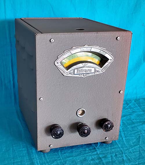
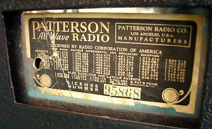
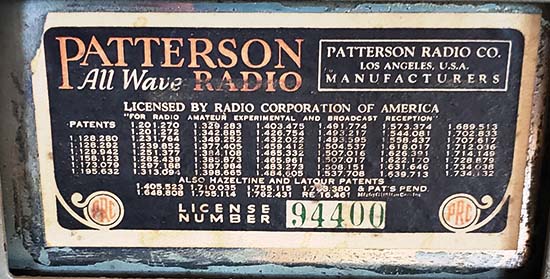
location of their entire operation. Emmitt Patterson and Patterson Radio Company was an exception. He used a different location for his office and official address of the company (1320 South Los Angeles St.) and avoided any overt connection to the Gilfillan Brothers.

Some of the "wanna-be" radio builders simply couldn't qualify to be sub-contractors. RCA insisted that a specific number of radios be produced and a specific minimum production level had to be maintained in order for qualification. Some LA radio builders just didn't sell enough radios to qualify. As long as these builders kept their radio building output below a specified level (usually less than 100 radios per week) RCA or Gilfillan wouldn't be at all interested in pursuing them for patent or license violation.

This sub-contactor license protection lasted through all of the 1930s. During the tough economic times of the Depression it helped a lot of radio builders that just couldn't afford to buy property, build a factory, buy tooling and essentially spend a fortune just to get started. The cost was minimal for the sub-contractor with just 5% of the radio-selling profit taken by Gilfillan who then split that with RCA. The RCA sub-contractor licensing through Gilfillan only required the builder to hire his own staff and come up with a good design to then start building and selling radios. Los Angeles radio manufacturers that were successful included Jackson-Bell, Packard-Bell, Kemper Radio Co., Patterson Radio Company, Breting Radio Company, Pierson-DeLane and many others.

By 1940, RCA was becoming less and less involved with the licensing and loosened many of the requirements. The major change was now the license to manufacture could be obtained directly from RCA. This really only affected the remaining companies that were successful enough to "go it alone." It spelled the end for Paul Breting who quit building radios in 1940. Emmitt Patterson had sold his end of Patterson Radio Company to Karl Pierson in 1937. Pierson partnered up with DeLaplane and continued to build the Patterson PR-15 under the Pierce-DeLane brand but also eventually dropped the PR-15 in 1940 and went into building two-way radios until WWII. Pierson did start up a short-lived company after WWII that built a couple of types of ham receivers. Emmitt Patterson quit radio altogether in 1939.

Patterson Radio Company - History

Emmitt Patterson - With the general history of radio manufacturing in Los Angeles covered in the section above, most of what was specific to Patterson can be detailed briefly. In 1920, Emmitt Patterson started his company called Patterson Electric Company. Although some sources indicate 1919 as the year, Patterson Radio Company literature states that 1920 was when the company started. Patterson sold mostly parts and electrical items. As Radio Broadcasting came on the scene, building your own radio was somewhat of a "rage." Plans were everywhere, in magazines, in newspapers and selling the components to build these sets was very profitable. By the mid-twenties, Patterson was able to start carrying a line of radios. Patterson changed the name of the company to Patterson Radio Company and selling radios (along with components) was their main function. In 1927, the RCA licensing for radio manufacturing structure changed the Los Angeles radio building landscape and all legal radio assembly had to be performed at the Gilfillan Bros.,Inc. plant on Venice Blvd. in LA. Patterson had gone into the Gilfillan sub-contractor mode by 1929 and was apparently, according to company advertising hype, already building "all wave" receivers by 1930. He probably had hired Ray Gudie as his chief engineer around 1930. Gudie was a talented radio engineer who designed Patterson's first popular and successful communication receiver, the Patterson "All Wave 10." The ten-tube superhet had great features and excellent performance besides selling for a fairly low price of $119.50 list. The "All Wave" was produced for a very short time and with a few minor changes became the "PR-10." Besides the PR-10 Communication Receiver, Patterson produced several Gudie-designed consumer-entertainment radios based on the PR-10 chassis "looks." Models 60AW, 70AW and 80AW were table models in cathedral type cabinets (six, seven and eight tube chassis, respectively.) The 507AW, 508AW, 510AW and 610AW were floor-models with seven, eight and ten tube chassis, respectively. It appears that none of the entertainment sets sold as well as the PR-10, which may have listed for $119.50 but was being sold for as little as $70.25 by many dealers (see the Henry's Radio Shop flyer in a section further down this page. Henry's Radio Shop in Butler, Missouri [Bob Henry] eventually became Henry Radio.) 

Ray Gudie, the PR-10 and Emmitt Patterson - The PR-10 and the other Patterson All Wave radios were quite successful. Some sources indicate that 50,000 PR-10 receivers were built although serial number analysis doesn't support this dubious claim. With the success of the PR-10 and the other Patterson radios, Ray Gudie felt that his significant contribution to Patterson warranted a raise. Whether Gudie asked in a manner that upset Patterson or whether Patterson was adamant against raises or felt the company just couldn't afford it, the entire query ended with Ray Gudie resigning. He wasn't unemployed long - maybe just the length of time it took to walk a few feet over to Paul Breting's office (Breting Radio Manufacturing) in the Gilfillan plant. Breting hired Gudie "on the spot" and the result was the fabulous Breting 12 receiver along with several other successful Breting receivers all designed by Ray Gudie. Of course, Breting's receivers were also built at the Gilfillan plant.


photo above: Breting 12 designed by Ray Gudie

What about Patterson post-Gudie?  Emmitt Patterson felt that he was a competent radio engineer and it's likely that Gudie had an engineering assistant that was still employed by Patterson. The Patterson Radio Company was in the middle of designing the new "Communications" PR-12 when Gudie resigned. The new PR-12 was based on a 12 tube entertainment radio Patterson was selling installed in a floor console cabinet. The new "Communications" PR-12 would replace the aging PR-10.

After Gudie resigned, Patterson took over the project but after a few weeks realized he (and anyone else in the company) didn't have a sufficient engineering background to enable him to complete the "Communications" PR-12 design. Apparently, a few prototype "Communications" PR-12  receivers have survived since a few have turned up in radio collections over the years. The known examples appear crude and very much like a prototype rather than a production receiver. It's likely that the "Communications" PR-12 wasn't really ever finalized for production. Of course, Patterson advertised the "Communications" PR-12 but that was (and still is) typical practice for marketing to get ahead of actual production.

photo above: Patterson PR-16C designed by Karl Pierson

Karl Pierson and Patterson Radio Co. -  Emmitt Patterson hired Karl Pierson to finish the new "Communications" PR-12 design. Pierson took one look at the PR-12 and scraped the entire project. Within three weeks, Pierson had designed the PR-16, an incredible receiver in some respects, with a power-house audio section capable of 20 watts output power. The PR-16 also featured parallel RF amplifier tubes (2-6D6s) which, in theory, increased the gain and reduced thermal noise. But, it also allowed the receiver to be advertised as having two RF amplifiers, even though there was only one set of RF coils per band and the receiver was essentially a single preselection front-end. Despite its quirks, the PR-16 put Patterson Radio Company back into the competition. It was $101 and it performed admirably although from a machine art perspective it suffered from a particularly stodgy appearance due to its bleak front panel layout with miniscule dial apertures and a heavily louvered cabinet. There are a few different versions, one with P-P 6A3 tubes and the later version with P-P 42 tubes. Also, the crystal filter was considered optional and the PR-16C versions did include the crystal filter.

Karl Pierson followed the PR-16 with a really great Patterson receiver that had the "looks" to go along with its fabulous performance, the PR-15. Although it shares the same style bezel as the Breting 14 (though the PR-15's bezel is slightly smaller than the Breting 14's), that's probably a result of the "parts sharing" that was a byproduct of using Gilfillan's stock. The PR-15 was a modern receiver with true double-preselection on all bands, crystal filter, push-pull audio from a pair of 6V6 tubes. The PR-15 was used by hams and professionals alike.


photo above:  Patterson PR-15 designed by Karl Pierson

Pierson-DeLane - It was 1937 and Emmitt Patterson really wanted to get out of radio. He sold his share of the Patterson "communication receiver business" to Karl Pierson, who then continued to build the PR-15 receiver. Pierson needed cash to continue production, so he partnered up with his business advisor, a man named DeLaplane, who also became VP of the new company, Pierson-DeLane.  The PR-15 continued to be produced with the Pierson-DeLane name on it up until about 1940, when the company started building two-way radios.

Patterson may have produced some entertainment radios late in the thirties but they weren't sold in any quantity. Patterson Radio Company was closed in 1939. Patterson himself retired from radio and lived the remainder of his life in Southern California.


The PR-10


photo above:  Patterson PR-10 SN: 6361 ca: 1934. Controls are left to right, B+ on/off & BFO switch, Band Spread tuning & push in for Tone control, Volume & AC power on/off (lower control), Manual Gain & AVC switch (upper control), Main tuning & push in for Band Switch, Trimmer control. The Main Tuning dial and Band Spread dial are illuminated and project a transparent red pointer-indicator onto the back of the dial. Note that the AM BC band (yellow Main Tuning dial) is calibrated in kilocycles but shortwave (green Main Tuning and Band Spread dials) is not calibrated and instead has a 0 to 100 scale. The R-meter works off of the AVC voltage so, as a signal is tuned in, the AVC becomes a more negative voltage and, since the meter is in the cathode circuit of the VTVM tube, the meter reads lower. To have the meter pointer appear to move "up scale" as a signal is tuned in the meter is mounted upside-down. The small viewing ports are Tone (left) which shows an increasing red arc as the highs are decreased. The Band Switch viewing port (right) shows the tuning ranges in Meters except for the AM BC which shows "BROAD CAST."

By 1933, listening to short wave broadcasts was becoming increasingly popular. Most new radios being sold featured some ability to receive at least one shortwave band. From the beginning, shortwave broadcasters knew they had to offer something different if they were going to attract listeners. For the most part, they all agreed that the programs on shortwave should promote and feature the culture of the country where the broadcast originated from. Idiomatic music, foreign languages, news direct from Europe and other areas of the world interested a new group of radio listeners. These may have even been some of the same radio DX enthusiasts from a decade earlier when medium wave radio broadcasting had started in earnest.

The market for shortwave receivers initially consisted of kit radios like Pilot Wasps and Pilot Super Wasps. Regenerative detectors with additional stages of both RF and AF amplification along with plug-in coils. The first successful superheterodyne shortwave receiver that was commercially-built was Hammarlund's Comet receiver from 1931. This receiver, although advanced in design and performance, still used plug-in coils. By 1933, short wave receiver kits were still available. One could buy the National SW-4 or SW-5 in kit form. National's SW-3 (fully assembled) was becoming popular. National began to offer the "top-of-the-line" AGS superheterodyne receiver. At the time, all National receivers used plug-in coils and separate power supplies.
 

The AW-10 Circuit - In 1933, Patterson Radio Company was one of the first commercial radio companies to offer a 10-tube communications receiver with coverage from 15 meters to 575 meters (20mc to 550kc) using band switching capability - no plug-in coils. The receiver was called the "Patterson All-Wave 10." It also featured an IF of 452kc, BFO referenced the tube grid LC to ground, AVC operation in all modes (no Manual Gain control) and a meter to measure signal strength. The AW-10 used a cadmium-plated chassis and the black knobs were similar to those used on Pilot radios.

Apparently, the AW-10's use of approximately 452kc for the IF resulted in leakage of signals from powerful coastal radio stations (ship-to-shore stations) operating in the 400kc region of the spectrum into the receiver's IF causing reception interference. Gudie changed the IF to 432.5kc for the new Patterson PR-10. Additionally, the AW-10 used a BFO that had a grounded-grid hook-up with a tuning condenser in the cathode-suppressor grid to ground (in addition to the Plate-Screen LC tuning.) Gudie revamped the PR-10 BFO to use just the tuned Plate-Screen LC that was magnetically coupled to the grid tickler coil. It's likely that these changes were incorporated into the AW-10 during its production run (probably not all simultaneously, either) and weren't necessarily strictly for the PR-10 introduction. It's possible that some AW-10s may have had PR-10 upgrades installed as part of a warranty repair since some examples seem to have later, PR-10 circuits or component values installed.

The PR-10 Circuit - The PR-10 didn't have an RF amplifier. Design Engineer Ray Gudie claimed that this arrangement was used because to attain "worthwhile" RF gain required extensive shielding that couldn't be accomplished in the PR-10 and maintain a reasonable selling price. The coil arrangement is unusual in that only one primary winding is used and that is only on the AM BC band coil. All Shortwave bands are coupled to the antenna by a fixed mica capacitor. There are no RF transformers used on the Shortwave bands, only parallel LC circuits are used for tuning. The "Trimmer" control isn't an antenna trimmer, it actually fine tunes the capacitance on the Antenna coils and the Mixer coils across each of the Shortwave bands, however, it is not connected when receiving the AM BC band. 

There are no adjustments on the Shortwave bands other than the padding capacitor on the 200M to 75M LO coil. All tracking alignment is accomplished with the trimmers on the main tuning condenser and the two padding capacitors (AM BC and 200M to 75M) and possibly bending plates on the tuning condenser, if necessary. Gudie recommends that only a single wire antenna be used and indicates that a balanced antenna (e.g., dipole) shouldn't be used. This is because the antenna input coils don't use primary windings except for the AM BC coil and that primary coil is grounded on one end. Only one Antenna terminal and one Ground terminal are provided.   

The AM BC band used a calibrated dial but the three shortwave bands used a 0-100 scale. Band Spread was provided on all four bands with only the Local Oscillator being tuned by the Band Spread dial (as mentioned, the Trimmer control is used to keep the Antenna and Mixer stages "peaked.") The LO coils for BC band and 200M to 75M were located under the larger shield can behind the tuning condenser. The BC band Antenna and Mixer coils were placed under the smaller shield can behind the tuning condenser. The Antenna and Mixer coils  for 33M to 15M and 75M to 30M were not shielded and were located on top of the chassis. The 75M to 200M Antenna and Mixer coils are next to the band switch under the chassis. The LO coils for 75M to 30M and 33M to 15M band were located under the chassis and can be identified since there are three coils on the form - the two oscillator coils and one common tickler coil.   >>>


photo above:
The top of the PR-10 SN:6361 chrome plated chassis with polished aluminum shields.


photo above: Under the chassis showing rubber friction drives for tuning. Note that the grounds are directly soldered to chassis. This photo was taken after restoration. All capacitors have been rebuilt (restuffed) so appearance is close to original. The .25uf AC bypass capacitor located on the Volume-AC switch is not original but was a vintage addition that was retained. (SN: 6361)

>>>  Three IF amplifiers were used with the IF set at 432.5kc. Gudie claimed in a magazine article that this IF was "quieter" and better suited since there were many ship-to-shore communications on 462kc and that was close to a popular IF of 465kc (used by Hammarlund.) Leakage of coastal station transmissions into the IF of older radios was somewhat of a problem if you happened to live on either coast. Usually, a tunable wave trap was part of the radio circuit which was tuned to the IF to keep transmitter signals from interfering with the listener's radio. Rather than install a wave trap that probably wouldn't be needed, Gudie suggested that the IF could be moved somewhat (~2kc) if any coastal station interference was encountered in the IF section of the PR-10. The three IF amplifier stages use slightly different transformers. The first IF transformer is very loosely coupled. The second and third IF transformers are identical in that they are designed to give the sharpest peak at the maximum response. The fourth IF transformer is "over-coupled" for a broad response to the second detector. The resulting IF bandwidth was very narrow and Gudie claimed it was as good as a crystal filter without loosing weak CW signals (that would be if the crystal filter was only used for narrowing the bandwidth.) PR-10 IF bandwidth was listed as 7kc but most are found to be much narrower (Patterson's alignment instructions state that the bandwidth is 1200 cycles each side of the signal or 2.4kc.) AVC and Manual Gain was provided as a switch that was combined with the Manual Gain control located just under the R-meter.

The BFO was switched from the front panel but the BFO frequency control was under the lid of the receiver with a knob provided for easy adjustment. Gudie coupled the BFO through a 0.1uf to the IF amplifier cathodes. This method provided a very strong clean note but had a tendency of "masking" weak CW signals. Later, this capacitor value was changed to .006uf to reduce the "masking" effect. In an early magazine write-up on the PR-10, Gudie suggested if weak CW signal masking was a problem the BFO should be loosely coupled to one of the second detector diodes instead of to the IF cathodes but this was never done in production.

The R-meter has its own VTVM circuit using a type 57 tube. With the grid of the VTVM connected to the AVC line, the varying negative voltage (which is dependent on the signal's carrier level) will cause the current through the meter to also vary.   >>>


photo above: PR-10 Pre-selector and PR-10 Receiver

>>> With calibration adjustments, the meter will give a relative carrier level reading expressed in "R" numbers which proceeded "S" units as a signal strength indicator. To have the meter appear to read upscale with negative voltage it is mounted upside-down. The power supply uses a 5Z3 rectifier and the filtering consists of a choke in the CT to ground connection and the electrodynamic speaker's field coil as a second choke with electrolytic capacitors on each side of the field coil (dual filters in one unit.) Although remote standby is not provided there is a panel switch for removing B+ to disable the receiver. Gudie claimed that one could duplex within 20kc of the tuned frequency to avoid disabling the receiver during transmit. A Volume control with AC power switch and a variable capacitance Tone control, that was actuated by pushing in the Band Spread tuning control, were provided. There was also an "overall" IF gain control that was a screw driver adjustment on the chassis. This set the maximum amount of IF gain that could be attained with the PR-10 in AVC or with the Manual Gain control at maximum. The audio output was from a type 59 tube and a 10.5" electrodynamic speaker was provided with the receiver (field coil R was 1500 ohms.) The speaker was not in a cabinet and it wasn't even mounted to a baffle board. The customer was provided with minimal instructions on building two types of suitable speaker baffles. The headset phone jack is located on the left side of the PR-10 and inserting a plug will disconnect the audio input to the type-59 tube and operate the headset from the type-55 First AF Amplifier tube. The AC power cord used was a brown cloth-covered line cord that was approximately six feet long. The type of AC power plug most often seen is a round bakelite type with embossed leaf design, usually brown in color, but black has also been seen.

Shown above is the PR-10 receiver SN:6361 with the PR-10 Pre-selector SN:1473. The Pre-selector is normally located on the left side of the receiver since this results in the shortest connections for tube heater voltage and B+ voltage. Patterson's recommended hook-up is to attach insulated wire leads from the 59 audio output tube pins and route them through one of the receiver's louvers to the Pre-selector power socket. B+ could be accessed at the speaker socket-plug. The Pre-selector output was connected to the PR-10 antenna terminal.

The Pre-selector added two stages of tuned RF amplification ahead of the PR-10 resulting a significant reduction in the image response at the higher frequencies. There was also some gain involved with using two tuned RF amplifiers but, for the most part, the PR-10 without the Pre-selector performed quite well on 160M, 80M and even 40M. The gain of the two RF amplifiers did help substantially with 20M reception since the Pre-selector was designed to have its maximum circuit gain at 20M. However, as the frequency was decreased the tube gain continued to increase resulting in the tendency of the Pre-selector to oscillate at lower frequencies when the RF gain was increased too much.

Most hams usually operated the PR-10 receiver with a resonant or tuned antenna. On 160M, 80M and 40M this type of operation afforded excellent performance. However, most SWLs used a random length end-fed wire antenna without any matching device. This would have seriously limited the ability of the PR-10 to pick up weak DX signals. With a non-resonant antenna, the Pre-selector would probably have helped on most bands. While examining several vintage QSL cards where the ham operator was using a PR-10 receiver, it was found that none were using the Pre-selector. However, all of these QSLs were for 160M or 80M operation.

Shown to the right are the chassis of the Pre-selector and the PR-10. The two tubes in the Pre-selector are type-58. Behind the power transformer is the audio output tube, type-59. To the right of the 59 is the type-57 VTVM tube (R-meter.) Next right is the type-55 Det/AVC/1st AF tube. In front of the 55 is the type-57 BFO tube. The knob of top of the can-shield is to adjust the BFO frequency. To the right of the 55 is the third-IF amplifier, a type-58 tube. Next right is the second IF amplifier, a type-58 tube. Continuing right and down is the first IF amplifier, a type-58. In the lower right corner of the chassis is the Mixer, a type-57 tube. Behind the left side of the main tuning dial is the LO tube, a type-56. In front of the power transformer is the rectifier tube, a type-5Z3. Note that the Pre-selector chassis is not chrome plated. Standard chassis finish on the Pre-selector was cadmium plating.


PR-10 and Pre-selector in Gray-Umber Wrinkle Finish

The standard PR-10 and Pre-selector finish was black wrinkle. There was also a deluxe finish available on the PR-10 that featured a chrome-plated cabinet. Shown in the photo left is PR-10 SN: 6102 from mid-1934 and PR-10 Pre-selector SN: 1247 from a somewhat earlier production. Both appear strikingly different in gray-umber wrinkle finish. Was there a gray finish available for the PR-10? It's not mentioned in any Patterson literature. Looking at the first-class quality of the paint finish, it's not immediately noticeable that the gray wrinkle paint is sprayed over the standard black wrinkle finish cabinet on both units. However, the gray paint is "real" wrinkle finish painted over a prepared surface and not "smooth" paint sprayed over an original black wrinkle. The quality isn't typical of amateur painting and a further indication of the professional nature of the refinishing is that the escutcheons were obviously removed for the repaint. These were originally mounted using rivets and the re-installation post-painting was also accomplished using rivets. Also, typical of a professional job, the escutcheons were nickel-plated before they were remounted. Also, the R-meter bezel was nickel-plated indicating that the entire repaint job was well thought-out and obviously wasn't some amateur job. Another observation is the lack of gray paint on the inside of the cabinet and on the cabinet lid lip. I've seen other repainting jobs that were "from the factory" (RME, for instance) and the repaint to a gray finish was accomplished in the same manner, that is, exterior surfaces only.    >>>

>>>   So, is this original Patterson work, the work of a professional or is it the work of a talented amateur? It's very unlikely that the gray paint is from Patterson Radio Company. It's far more probable that the repaint was done by professionals after a purchase of the PR-10 and Pre-selector as second-hand equipment. A clue might be with the former owner of this Patterson PR-10 and its matching Pre-selector, Arthur Sinclair W6FKQ (licensed in 1931.) Sinclair had a long career in the electronics field with Pacific Wholesale Supply as a sales representative along with many other functions in the San Francisco Bay Area. One of Sinclair's earlier jobs was as a civilian contractor working at the Alameda Naval Air Station servicing, repairing and rebuilding Navy radio electronics. This allowed him access to many of the Navy depot processes involved in rebuilding radio gear. Sinclair's son, Jim (from whom I purchased this receiver,) thinks that his father was able to get these two Patterson cabinets "repainted" at the Navy depot. Certainly possible. Another clue would be the color. In 1934, when the PR-10 was newly built, gray equipment was almost unheard of. Black wrinkle was the finish of choice at that time. The popularity of gray really started in the late-thirties and, by the post-WWII era, almost all radio equipment was painted gray. So, the most believable set of events would be that the PR-10 and Pre-selector were acquired by Sinclair second-hand in the early 1940s. He used his position with the Alameda Naval Air Station to access their radio repair depot processes and had the PR-10 and Pre-selector cabinets professionally repainted in gray along with having the escutcheons nickel-plated. These two Patterson pieces have spent the last seventy-odd years in the SF East Bay Area in Arthur Sinclair's home. Arthur Sinclair died in 2010 (age 94.)

It took about six months of informal planning to finally meet-up with Jim Sinclair at Lake Tahoe. He was going to be vacationing in the west from his Chicago-area QTH so we timed our meeting to allow Jim to bring the PR-10 and Pre-selector from his father's house in Oakland up to Lake Tahoe. Of course, the other attractions in and around the Lake Tahoe area were the primary reason for Jim's trip but the PR-10 purchase-delivery worked out to be convenient for both of us and took place on August 18, 2019.

PR-10 SN:6102 is in excellent condition on the exterior although there are various small nicks and other minor blemishes as would be expected on a 75 year old paint job. The chrome on the chassis has suffered from the SF Bay Area's somewhat salt-air moisture environment. Luckily, the PR-10 was stored somewhere fairly dry since the chrome is only lightly spotted and would probably "polish out" quite well. All I did was remove the dust and dirt using Glass Plus. I didn't do any "polishing." Under the chassis, SN: 6102 is complete and all original with the following exceptions. Three paper wax capacitors had been replaced with newer style plastic molded caps, ca. 1950s. The type-59 audio output tube's cathode bypass electrolytic was replaced with a 1950s vintage cap. The filter capacitor appears to be a vintage Aerovox, maybe from the early-1940s, perhaps a bit earlier. It isn't polished like the original filter was but has a vintage Aerovox paper label. All other parts appear original. Storage must have been thermally stable and fairly dry because the Velvet-Tuning is still functional and pretty smooth for 85 year old rubber. I replaced the missing rubber feet, the missing fillister-head panel screws and the two 1/4x20 bolts and washers that secure the chassis to the cabinet.


PR-10 Pre-selector SN:1247 is also excellent on the exterior and includes the seldom-seen "rosette" wooden knobs that were used on some of the Patterson PR-10 units. Since the chassis is cadmium plated its condition appears typical of its age with no oxidation other than the normal darkening and a few minor spots. Under the chassis appears complete and all original with the exception of one ceramic disk capacitor (ca.1950s) and two 50K resistors. One resistor appears to be early-1940s vintage while the other is 1950s vintage. These are the screen to cathode 50K resistors that are found on many PR-10 Pre-selectors. These resistors increased the grid bias and helped with oscillation problems. Again, the Velvet-Tuning is in very good condition and functions fine. I replaced the damaged rubber feet, the missing fillister-head panel screws and the two 1/4x20 bolts and washers that secure the chassis to the cabinet.


Patterson PR-10 Receiver Detailed Information

Tubes Used in the PR-10 and PR-10 Pre-selector

Pre-selector:  1RF - 58,  2RF - 58     Dial Lamp - #14 (2.5v @ 300mA or .75W)  or  #41 (2.5v @ 500mA or 1.25W)

PR-10:   Mixer - 57,  LO - 56,  1IF - 58,  2IF - 58,  3IF - 58,  DET/AVC/1AF - 55,  BFO - 57,  VTVM - 57,  AF OUT - 59,  RECT - 5Z3     Dial Lamps - #14 or #41

PR-10 Variations - The PR-10 didn't vary physically too much throughout its production. There are differences between the one and only published schematic and many of the PR-10 receivers but this is primarily due to the fact that the schematic was never updated. Patterson apparently didn't have time or the resources to publish any updated documentation. However, the PR-10 and the Pre-selector had engineering upgrades incorporated at the production line. See section below "PR-10 Production Wiring versus Schematic" further down this page for details on the circuit variations. The following are some of the physical variations.

1. The All Wave 10 had a cadmium-plated chassis while the PR-10 chassis was chrome-plated. The Pre-selector chassis was always just cadmium-plated.

2. The R-meter on the AW 10 had "Patterson ALL WAVE" printed on the meter scale while the PR-10 meter scale had just "PR-10" printed on it. The B&W artwork (Henry Radio flyer below) shows the AW-10-type meter installed on a PR-10 receiver. This could indicate that very early PR-10 receivers might have had the "Patterson ALL WAVE" meters while later production receivers were equipped with the "PR-10" meters.

3. Sometimes the dial escutcheons will appear bronze, other times dark silver and black. This might be a wear factor for the patina-type oxide finish that was originally supposed to look like pewter. Years of dusting or wiping the panel (or perhaps mild corrosion) resulted in the brass showing through giving the bronze-look to some escutcheons.

4. Three knob styles are found on various examples of the PR-10 and the Pre-selector. The earliest style (as seen on the AW-10) is a round black bakelite knob with convex face with a concentric ring near the rim shown in photo 1. This style is also seen on early PR-10 receivers (SN:5521.) However, the 1934 PR-10 artwork on the Henry Radio flyer (below) shows the "rosette" type knobs. As mentioned before, this artwork pictures a very early PR-10 with a "Patterson ALL WAVE" meter scale. These wooden (painted black) "rosette" knobs have actually been found on PR-10 Pre-selector SN:1247, which probably dates their use to the first part of 1934. Photo 2 shows the "rosette" knob. Both of these early style knobs were probably from Gilfillan's stocked parts. By early-1934, the latest style knob was being used - the "PRC knob" - shown in photo 3. "PRC" was embossed in the center of the knob standing for Patterson Radio Company indicating these knobs were made specifically for the Patterson. 

1

2

3

PR-10 Flyer from "Henry's Radio Shop, Butler, Missouri" - This PR-10 flyer was used by several discount radio dealers in May, 1934. Besides this "Henry's Radio Shop" example, I also have a "Seattle Radio Supply, Inc." flyer that is identical (other than the name of the dealer on the back.) The flyer was obviously written by Patterson Radio Company for any dealer to give to prospective buyers to furnish all of the details on the receiver circuitry, including the schematic.

To the left is the front cover of the flyer indicating the "40 and 2%" (42%) discount from list price. Note that this flyer indicates that Patterson started in 1920. Also in the last paragraph is the statement that "Patterson has built regular ALL-WAVE Receivers for four years." The assumption is that "regular" probably indicates entertainment radios with shortwave coverage since the sentence continues ",...and, coming to the Amateur field with this wealth of experience assures you of the ultimate in AMATEUR RADIO.," confirmation that the PR-10 (and the preceding ALL WAVE 10) was the first Communications-Amateur receiver that Patterson built. Handwritten note that "Shipping Pre-Paid."

"Equal Gain All Frequencies...Complete Band Coverage...No Coils to Change" One has to remember that in 1934, this was probably somewhat true. It did probably seem like the PR-10 had equal gain on all frequencies but that was probably when connected to test equipment rather than an antenna. There was a reduction in efficiency of most circuits at the time when the frequency of operation was increased. When connected to an antenna, the PR-10 behaves like a typical 1930s receiver in that signals in the AM BC band or 160M or 75M are much stronger and drive the R-meter much higher than a signal tuned in on the 16M shortwave band.

The high frequency coverage was somewhat better than most receivers. The typical "All Wave" receiver of the time covered AM BC up to 18mc. The PR-10 will usually tune to about 21.5mc (remember, the 15M ham band didn't exist at that time.) However, by 1934, National Company had announced that 10 meter coils were available for the FB-7 and AGS receivers. Hams were pushing into the higher frequency regions at the time. Mainly, because the 10 meter band openings were just beginning for that particular sunspot cycle and the DX reception was incredible.

"No coils to change" is a direct reference to National and Hammarlund. All National receivers at the time used plug-in coils as did Hammarlund's Comet Pro receiver.

The PR-10 "Deluxe" featured a chrome-plated metal cabinet rather than the standard black wrinkle. Price was $134.50
 

photo left: Henry's Radio Shop flyer for the PR-10 - front cover

To the right are the two inside pages with specific details about the PR-10.

The first paragraph contains important information in saying that the PR-10 was introduced in May, 1933. Also, that this flyer is one year later, or May 1934.

Particularly humorous is the third paragraph, "The PR-10 is not with Byrd at the South Pole. If all Radios were on the Byrd Expedition that are claimed, there would be no room for anything else."  At the time, it seemed every ad for almost any communication receiver indicated that the receiver model was part of the equipment Byrd took with him to the South Pole.

Note Distinctive Feature #38 - "Over 25,000 Velvet Dials in use on Patterson All-Wave Radios. Not ONE back for service!"   That certainly isn't the case today as almost all Patterson Velvet Dials either slip or have a rough feel to the tuning. The full details on restoring the Velvet Dial drive is in the "Restoration" section further down this page.

One other point of interest is the Guarantee. The PR-10 was guaranteed for six months. This included all components, even the vacuum tubes! The implication is that the warranty repairs were carried out by Patterson (at the Gilfillan plant.)


photo above:  This is the back page of the May, 1934 PR-10 flyer with all of the testimonials from various customers. Note that the letter from Berkeley, Calif. mentions his PR-10 serial number is 5734 and the letter from Seattle, Wash. indicates his PR-10 serial number is 5770. These are relatively low serial numbers for May 1934 if the total number of PR-10 receivers built was over 50,000. An examination of several PR-10 serial numbers will be required for determining if the SNs are sequential and exclusive to the PR-10.

More in "Serial Number Analysis" further down this page.
 

PR-10 Features That Became Standard for Communication Receivers - When the AW-10 was introduced in early-1933, only the Hammarlund Comet and National AGS were available as commercially-built superheterodynes. As the AW-10 evolved into the PR-10 (by May 1933) only the National FB-7 and the RME-9 had been added to the superhet line-up. Although some consider the improved RME-9D as the first receiver to offer all of the "standards" in mid-1934, the Patterson PR-10 was not far behind.
 

1. Consider that both the RME-9D and the PR-10 receivers have a carrier level meter for measuring signal level in "R's." Neither the Comet Pro nor the FB-7 or AGS had carrier level meters.

2. Another standard was band spread. Both the RME-9D and the PR-10 feature band spread along with Hammarlund's Comet Pro, but the FB-7 or AGS required special "band spread coils" for that function.

3. A tuned RF amplifier was included in the RME-9D but not the PR-10 or the Comet Pro or the FB-7. The AGS did have a TRF stage.

4. A Crystal Filter was included in the RME-9D and optional on the later Comet Pro. Also, optionally available on the FB-7 (as the FBX) and AGS (as the AGS-X.) The PR-10 didn't include a Crystal Filter (Gudie claimed the 2.4kc bandwidth allowed for "single signal" CW reception without the use of a crystal filter.)

5. A stand by function was very useful and it is found on the PR-10, RME-9D and the FB-7 but the Comet Pro and the AGS didn't have a stand by switch.

6. Front panel operated BFO frequency control was only found on the RME-9D and the National AGS-X receivers. All other receivers had the BFO frequency control under the lid of the cabinet.

7. A trimmer control was included on the PR-10 and RME-9D. The Comet Pro provided individual Mixer (WL) and LO (OSC) tuning along with bandspread. A trimmer control wasn't used on National receivers.

8. Band switching (no plug-in coils) was provided on the RME-9D and the PR-10. All other communication receivers of the time used plug-in coils.

9. A built-in AC power supply was used on the RME-9D, PR-10 and the Comet Pro. All National receivers used separate power supplies.


In this comparison, the PR-10 only lacks the tuned RF amplifier, front panel BFO freq-control and a Crystal Filter in the list of standards. The Crystal Filter was optional in all other receivers but was standard equipment for the RME-9D. If one purchased the matching PR-10 Pre-selector, then two stages of TRF were available, making the PR-10 one of the top receivers available in 1934. In examining QSL cards from the late-1930s, the PR-10 does show up occasionally as the station receiver indicating that it was fairly popular (especially in California.) The hams certainly found the price of $70.25 attractive and adding to that the Pre-selector, at around $20, the entire receiver package cost less than $100 for what was essentially a twelve-tube, double pre-selection receiver. Interestingly, most hams wouldn't even use a crystal filter (even on CW) as James Millen found out in a 1936 survey that ultimately spawned the HRO Junior.

The PR-10 "Learner's Card" - Some manufacturers didn't provide any nomenclature on the front panels of their communication receivers. Though this may have been economically driven, the argument provided was, "The owner of the receiver is a radio amateur. He knows what the control functions are. There's no need to label them." Of course, the instruction sheet or manual provided with the receiver did have the function of the controls shown and experienced hams only needed a minute or two to familiarize themselves with location and function of the controls. Radio novices might need more help so Patterson went one step further. The PR-10 came with a "Learner's Card." This was a heavy paper overlay that had cut-outs for all of the front panel controls with identification as to what the control function was. The new owner had to remove the knobs and then place the "Learner's Card" holes over the control shafts and then reinstall the knobs. The idea was that after a few days, the new owner would know the control functions and could take the "Learner's Card" off. Since most were discarded afterward, not many original "Learner's Card" examples survived.

photo above: Reproduction of the "Learner's Card" made from a surviving original.

Vintage Photo shows "Learner's Card" Installed on PR-10 - The photo to the right is from a "photograph" QSL card from W5DUK, Otto L. Pietaner from Kemph, Texas. The QSL is for a Phone QSO on 160M on October 10, 1935 with W9UIJ. The card is postmarked the next day. A good guess would be that the photo was probably taken earlier that same year, 1935. Of course, very apparent is that W5DUK has his "PR-10 Learner's Card" installed on his receiver.

W5DUK's H.B. transmitter is a 210 Crystal Oscillator, an 801 Buffer Stage, a pair of 203A tubes for the PA and a pair of P-P 830s as the Class B modulator. Antenna is listed as a Marconi (vertical but may have been a "T" configuration of wire construction) with a Collins Pi-network for matching.
 

AC Voltage Level Input Selection - The PR-10 allowed the user to select the proper AC input voltage depending on what his particular house voltage was. A three clip fuse holder allows the user to position the line fuse to select either 110vac to 115vac or 115vac to 130vac. The fuse holder was located behind a fiber board cover on the rear of the chassis. Nowadays, with most house line voltage levels at 120vac or slightly more, one should place the fuse in the 115vac to 130vac position. This will result in the proper tube heater voltages and close to the specification B+ voltage. The photo to the right shows the fuse in the 115-130vac position.

Antenna Considerations - Ray Gudie suggested that only an end-fed wire should be used as the antenna because of the grounded parallel LC networks used for tuning. Using a dipole (balanced feed line) antenna would have required a primary winding on the antenna input coils and the PR-10 didn't provide a primary winding on the short wave coils. Gudie further suggests that the antenna size should be 75 feet to 200 feet long and configured as an inverted "L" antenna. Gudie doesn't go any further but typically the ham installation would have included an "L" network for matching the single-wire unbalanced input to the transmitter link output which would have one end of the link grounded for an unbalanced output. The "L" network could have provided an unbalanced "tuned antenna" for the PR-10 which would have been ideal for reducing images and providing strong signals.

Today, many hams use a "tuned dipole" fed with open feed line since this antenna is essentially "multi-band" in that you can tune it to match almost any frequency. These antennas are balanced but always go to an antenna coupler (tuner) that matches impedance and provides an unbalanced output for the radio equipment. This is an ideal set-up for the PR-10. Just use RG-58U coax to run from the tuner to the receiver with the shield connected to the ground terminal and the center conductor connected to the antenna terminal. With this set-up you can use the tuner to provide the PR-10 with a matched antenna for just about any frequency resulting in stronger signals and it will help somewhat with image rejection, too. I've used the PR-10 alone (that is, without the Pre-selector) with this type of antenna set-up and have found the performance on 80M and 40M to be fabulous.

Main Tuning Dial Graph - One of the problems with the PR-10 is the 0 to 100 scaling used on shortwave. Add to that the use of wavelength for identifying the tuning ranges. It all ends up in confusion as to where in the RF spectrum the PR-10 is tuned.

I've created the graph to the left to aid in tuning the PR-10. Each plotted line is identified by the band switch wavelength identifier. However, the graph is in frequency rather than wavelength which should be easier to understand.

Be sure to set the Band Spread to "0" for this graph to be accurate. Also, there will be slight differences for each PR-10 but, overall, the graph should be a good guide as to where your PR-10 is tuned.

Here's the Main Dial settings for WWV with Bandspread at "0."

2.5MC =  49.5 (200M-75M)    10.0MC = 84.5 (33M-15M)

5.0MC = 65.5 (75M-30M)        15.0MC = 48.0 (33M-15M)
 

Patterson's documentation mentions that a "tuning graph" was supplied with each receiver. Few, if any, have survived.
 

PR-10 Bandspread Instructions - Patterson provided instructions for setting the Main Tuning for complete band spreading of the ham bands but it was confusing and didn't specify whether the band spread dial was set to 0 or to 100, in fact, it showed both on some of the ham bands.

Shown to the right is an easy way to set up the receiver to band spread each ham band. Band Spread is set to 0 for the highest frequency then tune the Band Spread to higher numbers for lower frequencies within the selected band.

                                                  80M                                           40M                                                 20M

     Set Band Sw to:        200M-75M                                 75M-30M                                          33M-15M

     Set Main Dial to:              7.0                                              28.5                                                  52.5

          Freq = BS                 4.0mc = 0                                  7.3mc = 0                                          14.4mc = 0
                                              3.9mc = 31                                7.2mc = 29                                        14.3mc = 26.5
                                              3.8mc = 51.5                             7.1mc = 46.5                                     14.2mc = 42.5
                                              3.7mc = 66.5                             7.0mc = 61                                        14.1mc = 51.5
                                              3.6mc = 79                                                                                          14.0mc = 68
                                              3.5mc = 90


Patterson PR-10 Pre-selector - Detailed Information

The Patterson PR-10 receiver didn't have an RF amplifier ahead of the Mixer and Local Oscillator. Although there are tuned Antenna LC circuits (not RF transformers,) which give a slight edge to image rejection, it would be normal to encounter images beginning around 30 meters or 10mc. The larger and higher the antenna the stronger the signals will be and the more likely that an image response will be tuned and heard 865kc below a strong station's actual frequency. Of course, our tendency today is to tune in WWV at 10mc and to check for images at 9.135mc. But, this test will show the images at their absolute worst. WWV is usually a very strong signal at 10mc, also its signal content is very, very recognizable. This makes the 10mc WWV image really super-easy to spot. The reception of an average CW ham signal on 14.090mc showing up as an image on 13.225mc would be very difficult to hear or to find. But, back to preselectors,...  The increased selectivity provided by two tuned RF amplifier stages would provide an improved image ratio which translates into much weaker image signals. Of course, there's also the benefit in actually providing some Tuned RF amplification which might help in weak signal reception. Reduction of images and increased RF gain are the reasons to use a pre-selector.

Patterson started to offer the PR-10 Pre-selector around 1934. The PR-10 Pre-selector production was limited with probably only a thousand (or so) built. It provided two stages of tuned RF amplification using two type-58 tubes. The heater voltage and the B+ had to be taken from the receiver that the Pre-selector was going to be used with. Although designed specifically for the Patterson PR-10, the Pre-selector could be used with almost any other Patterson All Wave radio or with any other receiver that didn't have a TRF stage ahead of the Mixer and LO. Since 2.5vac is needed for the heaters, it would be necessary for the main receiver to provide that voltage along with a B+ level of around +225vdc. It was possible, if the intended receiver operated with six volt heaters, to change the Pre-selector tubes to two type 6D6 tubes and it would still function as designed.

In the hook-up, Patterson suggested that the heater voltages could be accessed at the type-59 tube in the PR-10. The Pre-selector's plug-in power cable had a green and a black wire for the heaters and a red wire for B+ (screen.) Each wire had a terminal loop at the end with the Green wire going to pin 1 (chassis), black going to pin 7 (2.5vac) on the type 59 tube. The loops were slipped over the correct tube pins and then the tube reinserted into its socket. One had to be sure the wire insulation was fully keeping the wire loops from shorting against the chassis. B+ Screen was accessed at the Speaker socket using pin 4. The Pre-selector power cable plug connections are Pin 1 - 2.5vac,  Pin 2 - B+ (screen voltage level,)  Pin 3 - Preselector Output,  Pin 4 - Chassis. The power required for the Pre-selector was seven watts.  >>>


PR-10 Pre-selector SN: 1473

>>>   Patterson recommends an end-fed wire for a receiving antenna and that no ground connection should be used between the PR-10 ground terminal and the Pre-selector ground. Since one side of the tube heaters is grounded in both the PR-10 and Pre-selector, a common ground connection already existed.   

As with the PR-10 receiver, Ray Gudie again chose to not use a primary winding in his tuned circuits. The antenna is capacitive coupled to parallel LC "tuned circuits" on the grid inputs. This resulted in strong signal levels but lacked the selectivity gained by using actual RF transformers for tuned circuits. The tuning dial is scaled 0 to 100 with 100 being a fully-meshed tuning condenser and thus the lowest tuned frequency for the particular band selected. This matches the PR-10 short wave tuning and band spread dials.

The left control turns the tube heaters on and also is the RF gain control. Patterson's brief instructions warn users that advancing the RF Gain control excessively can easily over-drive the PR-10 causing oscillation or distortion of the received signal. The RF gain should only be advanced to just before the oscillation point on higher frequencies and much less advanced on lower frequencies. The center control tunes the Pre-selector and, when pushed in and turned, selects the particular tuning range desired. The tuning range is shown in the hole above the tuning knob. The right control selects "direct" which bypasses the Pre-selector and connects the antenna directly to the PR-10 receiver or "pre-selector" if the Pre-selector is to be operated ahead of the PR-10 receiver.

PR-10 Pre-selector Variations - The Preselector didn't use a chrome-plated chassis. All chassis appear to have been cadmium-plated. Almost every example of the PR-10 Pre-selector will show something different in construction or components. I've been able to examine four Pre-selectors and all had some variations in construction.

One interesting variation found on SN:1473, which shows the lack of parts or economical use of what parts were on hand, is the use of tube sockets tagged as "2A5" but having a cloth identification ring with "58" printed on it that is glued over the "2A5" ID. Also, the four pin socket on the rear of the chassis that is for heaters, B+ and Antenna inputs is marked "SPEAKER." I assume that originally this socket also had a cloth identification ring installed. My guess is that not all of the Pre-selectors will have this variation and most will have the properly ID'd tube sockets. NOTE: Pre-selector SN: 1247 has the "SPEAKER" socket but the two tube sockets are stamped/white-filled with "58" identifications.

Another oddity on SN: 1473 is that the tuning dial doesn't clear the sides of the cabinet. Some of the Pre-selector cabinets had the sides cut in an arc that allowed easy removal of the chassis. This example has no relief cuts and it is somewhat difficult to remove the chassis requiring sliding the chassis to one side and working the dial out pass the cabinet side before the chassis can be removed.    NOTE: This "no relief cuts" on the cabinet was also found on Pre-selector SN: 1247. Perhaps the "arc'd sides" example that was seen was an owner's solution for easy removal of the Pre-selector chassis from the cabinet.

Serial Number 1473 shown in the photographs left and right has an additional shield that is soldered under the chassis. The sheet metal appears to have been professionally cut (or well-done, anyway) and the soldering appears first rate. My guess is the shield isn't factory installed though. It's the only time I've seen a shield installed on a Pre-selector and it is not shown in any factory advertising artwork. It's purpose seems redundant since the Pre-selector is shielded when installed in the cabinet. However, the shield may provide "tighter" shielding and higher capacitance to reduce the tendency of the Pre-selector to oscillate.

Additionally, Serial Number 1473 has a 50K resistor between the screen and cathode of the first RF amplifier tube. This would increase the grid bias in relation to the cathode potential and reduce the gain of the tube. It was probably installed to reduce the tendency of the Pre-selector to oscillate if the Gain is advanced too far. The soldering appears to not be factory but is first rate work and the resistor used is a B.E.D. which would be period for 1934. This might be an after-market upgrade installed under warranty or recommended from Patterson to PR-10 Pre-selector owners.   NOTE: In SN: 1247, both 58 tubes have a 50K screen to cathode resistor. In this Pre-selector the two 50K resistors are a much later vintage than the mid-thirties and are probably late-forties vintage. This seems to eliminate the warranty possibility. I haven't found anything in Patterson literature about the Pre-selector that details this resistor addition. The instructions mention more than once that the Pre-selector gain should only be advanced slightly on lower frequencies otherwise oscillation will occur. Based on what's written in the instructions, one would assume that advanced RF gain and resulting oscillation must have been a problem. Somewhere (that I haven't found yet) this 50K resistor addition must have been published as a partial solution.


PR-10 Pre-selector SN: 1473 with shield installed (not original.)

RF chokes on some versions were made by National Company while earlier chokes appear to be a larger solenoid-type mounted to the chassis. The National RFCs appear to be factory soldering installations. SN: 1247 has the large solenoid RFC and the smaller RFC mounted on a wooden dowel.

Some versions of the Pre-selector have smaller diameter coil forms. Shown in the photos are the most often seen, larger style coils

Note on SN 1473 that the .25uf bypass capacitor is mounted at the rear of the chassis and is connected to the black wire on the power socket. This wire is to the tube heaters and power on switch. The published Preselector schematic shows this capacitor bypassing the B+ (screen supply in the PR-10,) not the tube heaters. This capacitor is a Consolidated Red Head Brand which isn't original and was obviously part of a repair that was incorrectly installed. Although original artwork shows the B+ bypass capacitor installed by the second RF amplifier tube there wasn't any room for that location because of the National RFC installation. The capacitor was installed by the power socket. SN: 1247 shows an original installation. Other differences can be seen when comparing the band switches, the chassis grounds for the Pre-selector "in-out" switch, minor variances in component mounting and the location of the antenna coupler adjustment.  

All indications are that the Pre-selector was evolving as it was being produced. Unlike the PR-10 receiver that was very consistent in production, the Pre-selector seemed to be subject to change depending on many factors with parts availability and on-going redesign being the most prevalent reasons. It also seems from the two examples here that perhaps some Pre-selectors were upgraded later. Whether these upgrades were installed by Patterson Radio Company (unlikely) or by radio dealers or by ham owners is unknown. As far as I know, there isn't any documentation regarding any after-market upgrades for the PR-10 or the Pre-selector (other than the BFO coupling suggestion in Gudie's magazine article on the PR-10.)


photo right: PR-10 Pre-selector SN: 1247 - note the "rosette" knobs


photo above: SN: 1247 under chassis. Note the one RFC mounted on a wooden post and the other large solenoid choke with aluminum shield.


Schematic Errors and Engineering Changes

PR-10 Production Wiring versus the Schematic - If your PR-10 requires any in-depth troubleshooting you're sure to notice that the receiver doesn't agree with "the one and only" published schematic. Apparently, documentation wasn't a priority at Patterson. That was also true at Breting and their schematics are fraught with errors that were never corrected (neither were Patterson's.) Scant documentation was typically common with most of the West Coast radio builders that were operating out of the Gilfillan Bros. plant.

The following is a list of discrepancies I've found in the 1934 version PR-10 receiver versus the schematic. It is noted in the text whether the discrepancy is an error or an upgrade.

1. B+ "Candohm Resistor has one more resistor in the package - six terminals instead of the five shown on the schematic. A 100 ohm winding between the Sensitivity control and the shown 50 ohm winding prevents "max'ing" the sensitivity by full-on Manual Gain (minimum R) and having the Sensitivity pot set to "Max" (minimum R.) If these were the settings then still 100 ohms would be in the circuit preventing taking the cathode of the last IF amplifier directly to ground. It appears that even the AW-10 used a six-terminal Candohm resistor which seems to indicate that this is probably a schematic error and not an engineering upgrade.

2. BFO coupling capacitor will probably be .006uf while the schematic shows 0.1uf. Original PR-10 did use the 0.1uf but it masked weak CW signals. Changed to .006uf, probably in 1934, but schematic never updated. The 1934 Operation Instructions for the PR-10 indicate that the correct value is .006uf and if more BFO injection is desired, then a 0.1uf capacitor can be installed in parallel with the .006uf. Ray Gudie (the PR-10 designer) mentions two methods of BFO coupling in an early magazine article on the PR-10, the standard IF cathode feed with a 0.1uf capacitor or lightly coupling the BFO to one of the second detector plates. The latter was never done as part of production. Upgrade.

3. First IF transformer plate coil B+ bypass capacitor shown as 0.1uf on schematic but .05uf is usually installed and .05uf is the value shown on the parts list. Schematic Error.

4. IF amplifier AVC tc capacitor shown as 0.25uf on schematic but 0.1uf is usually installed. Gudie mentions that the AVC action is slow enough to not respond between "the dot and dashes" of a CW signal but was fast enough to keep 20M phones signal constant. Probably when the BFO coupling capacitor was changed to a .006uf, the AVC tc was also changed to make the AVC response faster to benefit phone signals and Gudie figured that most CW ops would operate the receiver with the AVC off in Manual Gain. It's apparent from the lack of a Manual Gain control on the AW-10 that Gudie initially intended the CW operators to run the receiver with AVC on at all times. With the PR-10, Gudie provided a method to allow the CW ops a choice and eventually, by the 1934 versions, had pretty much decided to optimize the PR-10 for communications and that meant CW reception. Upgrade. Interestingly, Gudie's first receiver design for Breting Radio Co. (Breting 12) also used the idea of an AVC circuit that was "always on" and couldn't be turned off. Reducing the RF or IF gain control would reduce the AVC action which was supposed to allow the operator to find the perfect balance of sensitivity and reduced AVC action for CW reception, or at least that was Gudie's intent.

5. Cathode resistor on the type-59 audio output tube is shown as a 500 ohm resistor on the schematic but usually a 600 ohm resistor is installed. This slightly increased the negative bias on the grid in relation to the cathode for better audio quality. However, this could also be a result of stock parts availability since the change is only 20%.  Interestingly, Russ Webb's Patterson AW-10 also has a 600 ohm cathode resistor for the type-59 tube. So, the resistor value may have been 600 ohms all along but erroneously shown as 500 ohms on the schematic.    >>>

>>>   6.  No shielded wiring is shown on the schematic but there are shielded wires from the Antenna input to the Antenna Coil switch, from the Tone control, from the Volume control and to the head phone jack. These shielded cables are used even in the AW-10 receiver so this was probably just an oversight when the schematic was drawn.

7. Schematic doesn't show the AC power switch or an AC bypass capacitor - if there was one. The capacitor value found installed on my PR-10 SN: 6361 was a .25uf but since the capacitor is not an Aerovox (it's a Consolidated Red Head Brand) and an AC bypass cap isn't specifically shown on the parts list and the .25uf value seems rather high for an AC bypass, I doubt its originality. PR-10 SN: 6102 doesn't have an AC bypass capacitor installed. Schematic oversight on just not showing the AC power switch.

8. Most receivers will have a 300 ohm resistor installed from the cathode of the VTVM tube to the + on the R-meter. Not shown on the schematic. Oversight or possible upgrade. (Thanks to Don W9BHI.)

9. Most receivers will not have the 250K resistor from the First IF Amp grid (IF secondary coil to AVC line) shown on the schematic. Upgrade. (Thanks to Don W9BHI.)

10. A small brass trimmer capacitor is in parallel with the Mixer stator on the Trimmer control to allow balancing the two sections of the Trimmer to the LC of the Mixer and Antenna stages. Not shown on the schematic and not mentioned in the Patterson Alignment Instructions. Schematic oversight.

11. Local Oscillator tube is not identified on schematic. It's a type-56. Schematic oversight.

12. BFO tube grid is connected to chassis ground inside the BFO coil can. This connection isn't shown on the schematic. Schematic oversight. (Thanks to Stan Carter.)
 

Documentation Issues - Other problems with Operating and Alignment Instructions and with the Parts List.

1. Alignment instructions casually mention the 100pf padding capacitors that are in the circuit for adjusting the lower end tracking on the AM BC band and on the 200-75 meter band. The instructions are not specific about their adjustment. The padding capacitors are accessed on the right side of the chassis when facing the front of the chassis. 

2. If you're looking for the .05uf bypass on the Mixer plate coil (B+ side) and the 0.1uf IF amp grid coil AVC tc capacitor they are under the shield can of the first IF transformer. Same for the 0.1uf AVC tc capacitor for all of the IF amps. It's under the shield can of the third IF transformer.

3. Errors in parts list No. 101, items 112 thru 116 are electrolytic capacitors (although only 112 and 113 are used in the PR-10) are shown with decimal points in front of their actual value, e.g., the 10uf 25vdc cathode bypass for the 59 used in the PR-10 is shown as .10uf 25v.  

Above is a "red-lined" schematic of the PR-10 receiver showing the engineering changes made in production by 1934. These "minor" changes are also described in the text above.

PR-10 Pre-selector Schematic - The schematic is shown to the right. As with the PR-10 receiver, this is the only schematic that was ever published for the Pre-selector. In examining serial numbers 1473 and 1249, I found these Pre-selectors did agree with the schematic with one exception. That is the 50K resistor added between the screen and the cathode of the First RF amplifier. I've marked the 50K location in red on this schematic. However, I'm not sure that it was an official "engineering change" and may have been added by a repair technician or by a talented owner.

The 50K resistor doesn't seem to dramatically effect performance but may have provided some stability to the first stage and helped with oscillation when the RF gain was fully advanced. The resistor will increase the grid bias on the first RF amp by increasing the positive voltage on the cathode (in addition to the 35K that's original.)
 
UPDATE: Pre-selector SN: 1247 has 50K resistors installed on both type-58 tubes. These are later types of resistor styles which seems to indicate that this installation was a "known upgrade" though I've not found any Patterson paperwork that shows this upgrade. Was it "common knowledge" among PR-10 owners? Was this upgrade published in one of the ham magazines of the day? The 50K resistor mod must have been circulating around while the PR-10 and Pre-selector combo was still in use in ham shacks. This would imply the publication of the mod must have been in some pre-WWII magazine. My guess would be 1935 to 1937.


Hooking up an Electrodynamic Speaker to the PR-10

Operating the PR-10 without the Original Speaker - Let's face it, nearly all of the original PR-10 electrodynamic speakers have become separated from their parent receivers over the years. The original field coil was part of the receiver's power supply filtering providing a choke inductor function along with a certain amount of DC resistance. That DC R was shown as 1500 ohms on the schematic. Any electro-dynamic speaker with a field coil DC R that is near 1500 ohms will work. Avoid field coils that are less than 1000 ohms. You can use, e.g., a 750 ohm field coil and series a wire-wound resistor that's 750 ohms with a 25 watt rating. The field coil will act as the choke and the additional resistance will make up the DC R necessary for the B+ to be close to specifications. Don't use just a 1500 ohm 25 watt WW resistor. No filtering will result and the hum level will be higher than normal for the PR-10. However, a lower than 1000 DC R field can be used with a WW resistor to make up the resistance necessary.

It's also possible to just use more than one choke connected in series to substitute for the field coil and then use a standard PM speaker with audio output transformer the matches the type-59 output tube. I've used up to three series-connected chokes to get the DC R up to 1500 ohms with no problems. Be sure the chokes are rated for around 90mA or so. 

Audio Output Transformer - The PR-10 doesn't have the output transformer mounted on the chassis. It was mounted on the original speaker. The transformer necessary should have a primary impedance of  approximately 7,000Z ohms. The audio output is a single tube so only Plate and B+ connections are necessary. You can use a P-P CT-type primary but your connections depend on the impedance. You might only use one end to CT if that is near 7000Z. If the winding is 3500Z each side of CT, then use the entire winding (don't connect CT to anything.) Be aware that these are impedance measurements, not DC resistance. The DC resistance will be dependent on the watt rating of the transformer. Use a transformer that's rated for a minimum of 3 watts. DC resistance should be around 250 ohms to 350 ohms on the primary. It's not critical. Anything close will work fine.    >>>

>>>  Specifics for a type-59 tube are plate load 7K, watts output with 250vdc B+ is about 3 watts if self-biased with 500 ohm resistor. The secondary impedance should match the voice coil impedance of the speaker to be used. If you're using a modern speaker combined with a choke to substitute for the field coil then you'll know what the voice coil Z is. If you're using a vintage field coil speaker that doesn't have an output transformer already mounted then you probably won't know what the voice coil Z is. Most voice coils were between 2.5Z ohms up to about 8.0Z ohms. Try 4.0Z ohms for vintage field coil speaker voice coil Z and it will probably sound fine. Remember, the speaker voice coil is rated as a "nominal" impedance because the Z will vary with frequency and normal listening is a constant mix of frequencies. Speaker nominal Z is "the lowest impedance that a VC will present as a load when operating under normal listening conditions" - pretty vague,...so don't worry too much if the VC is 3Z, 4Z or 8Z. 

Connecting the Speaker to the PR-10 - The PR-10 has a four-pin socket on the rear chassis for the speaker connection. The two larger pins are for the field coil and one of the small pins will go to the type-59 plate while the other one is jumped to B+ at the large pin that runs B+ to the type-59 screen and to the rest of the receiver circuitry. The proper connections are: 

Pin 1 (+HV) - should connect to the field coil input. 
Pin 2
(B+ Screen) - should connect to B+ on audio output transformer.
Pin 3
(59 Plate) - should connect to PLATE on audio output transformer.
Pin 4
(B+ Screen) - should connect to field coil return.

On field coils, usually the input will be the inner most start of the winding and the return will be the outer most finish of the winding (highest voltage nearest the pole piece for highest magnetism.) If the input or return can't be determined, it usually isn't too important. Just experiment with both field connections and use the one that seems to provide the least hum and the best sound (although you probably won't be able to tell any difference.)

Most audio output transformers are marked but some only have color coded wires. Normally, the red wire is connected to B+ and the blue wire is connected to the Plate. If neither color code or markings are present, the inner most wire nearest the iron core is the start of the transformer primary winding and this will be the B+ connection and the next wire toward to outside of the windings will be the Plate connection. The two remaining outer-most wires are for the voice coil of the speaker.


Restoration of the PR-10 and PR-10 Pre-selector

To really enjoy using the PR-10 and PR-10 Pre-selector both units should be in very good mechanical condition and excellent electronic condition. Just about any 80+ year old device is going to have problems that require restoration. Other than the standard "replace the original capacitors" type of rework, your Patterson PR-10 equipment is certain to have problems with the rubber-cushion, rim-drive tuning system and may have problems with the tuning condenser rubber mounts. The BED "dog bone" resistors used at this time in radio manufacturing were somewhat unstable and many will have "drifted" in value to the point where they will affect circuit performance. After the rebuild, full IF and RF alignment will be required. With all of this rework performed, the PR-10 and Pre-selector will provide an excellent operational example of a top receiver design from the period. Whether that performance would be considered competitive today is subjective and probably depends on how dedicated the user is to "experiencing the past."  


Mechanical Problems with the "Velvet Dial" Rubber Friction-Drive Tuning

The PR-10 receiver and matching Pre-selector are both fraught with mechanical tuning problems due to rubber deterioration in the "Velvet Dial" friction drive tuning system used in both units. Since the rubber used is now 80+ years old, all of the rubber drive wheels are no longer pliable and usually are glazed and "hard as cement." Naturally, this affects the gripping ability of the drive wheel and causes "slipping." The hardened rubber wheel generally will have a flat spot where it was against the dial rim and when tuning the receiver the action is not smooth, usually is noisy and feels like the rubber drive is "lumpy."

The other mechanical problem is the Main Tuning Condenser that is mounted to the chassis using natural rubber mounts. After 80+ years these have deteriorated to the point where the dial rim is rubbing against the tuning shaft. Most PR-10 receivers and Pre-selectors will have their natural rubber tuning condenser mounts "flattened" by the weight of the condenser thus lowering the position of the tuning condenser and allowing the dial rim to rest on the tuning shaft. As the tuning knob is turned the shaft to dial rim contact causes "roughness" to the feel and a scraping noise as the shaft rotates.

It's interesting to note that the PR-10 I bought back in 1965 didn't have any problems with the tuning. The receiver was just 31 years old at the time. The next PR-10 I bought, in 1985, did have the hardened rubber drive wheels and rough tuning. At that time, I just reconditioned the rubber by turning the hard rubber in a lathe and removed the surface a little at a time until there was good condition rubber on the contact surface. That worked at that time. The PR-10 in this restoration section was purchased in 2005. Both the rubber tuning wheels and the rubber condenser mounts were shot. It's interesting to see the progression of deterioration over decades and in three different examples of the same type of receiver. I didn't keep the earlier receivers so this observation is from my memory as a fifteen year old on the first PR-10 but the second PR-10, since it required some rework, is still a vivid memory. The restoration of the PR-10 SN: 6361 in this article took place in March 2016.

The detailed procedure to repair both of these problems follows.

Restoration of the "Velvet Dial" Rubber Friction-Tuning - Perhaps the most common mechanical problem of the PR-10 and the PR-10 Pre-selector is deterioration the rubber cushion friction tuning. Mounted to the tuning shafts of both the Main Tuning and the Band Spread Tuning is a metal cylinder that is mounted with a set screw to the tuning shaft. The metal cylinder piece has a rubber cushion between it and the dial rim. The cylinder-rubber piece (called the drive wheel) is conical spring loaded to push the rubber cushion against the dial rim. Both the Main Tuning and the Band Spread controls are dual purpose in that by pushing the knob moves the shaft inward where it engages a slot inside the "U" shaped piece that provides bearing support and carries the control position indicator. These "U" shaped piece is set screw attached to the control shaft. Main Tuning also acts as the Band Switch when pushed in and turned. The conical spring-loading will return the shaft back to its normal position as the Main Tuning. Band Spread works in the same manner to actuate the Tone control.

It's unfortunate that thirties-vintage rubber doesn't age well (and these Velvet Dial rubber treads are all 85 years old or more.) All PR-10 and Pre-selectors (and any other Patterson that uses the rubber cushion tuning) will have "flat spots" on the rubber tread where it was left in the same position over the decades of storage. Most of the rubber treads are glazed and hardened to the point where they are about as pliable as cement. This causes slipping of the tuning dial and a rough, lumpy feel to the tuning.

To disassemble the tuning shafts for either Main Tuning or Band Spread first loosen the set screw on the rubber drive wheel. You can now extract the tuning shaft out the front of the chassis. Keep track of the fiber washer as it has a recessed area for the conical spring to set into. Usually, you'll have to dress down the front part of the shaft because of set screw marring from the tuning knob. 

To rebuild the drive wheel will require two 3/4" diameter rubber feet (like what is used on a lot of electronics equipment.) Use new rubber feet that mount with a screw and nut not "stick on" types. Be sure the rubber feet you buy are the domed-shape (as shown in the photos.) Make sure the feet are no taller than 3/8". These types of rubber feet will have a washer molded inside defining the mounting hole. These washers are easy to remove with needle nose pliers. With the washer removed, use a 1/4" diameter drill bit to enlarge the hole. This can be done by hand and be sure to use the drill bit from both directions as this will cleanly cut the hole in the rubber. Now glue (I used Duco cement) the rubber foot to the metal cylinder backing piece. Insert the tuning shaft through the rubber and backing piece. Now, attach a knob to the front of the shaft and slide the rubber side up against the back of the knob and tighten the set screw of the backing piece. This will hold the rubber foot centered while the glue sets up.   >>>

photo right top: The original dial drive with original rubber. Note that the dial rim is setting on the tuning shaft

photo right bottom: The rebuilt rubber drive tuning showing using a rubber foot for the drive.

>>>  When the glue on the rubber drive wheel is set then disassemble and reassemble the parts back into the receiver.  You'll want the shaft to protrude about 15/16" from the front chassis bearing for tuning and about 3/4" when pushed in. Once the assembly is complete try the tuning. It should be ultra-smooth feeling with no slipping of the dial. Even minute movements of the tuning knob will result in a minute movement of the tuning dial. Just like when it was new.

If your Main Tuning dial rim is rubbing against the tuning shaft you'll still have a rough feel to the tuning. You'll need to replace the Tuning Condenser rubber mounts. Procedure follows next,...

photo right: Close up of original rubber - hard as cement and well-glazed.
photo far right:
New rubber wheel and the other tuning parts ready to install

Alternative to the Rubber Feet - Stan Carter and some other PR-10 fans have found that there are rubber faucet washers that are an exact match to the original rubber cushions on the Velvet Dial tuning drive. I think one would have to go through the faucet washers at the hardware store to find which particular ones are a match. Knowing Patterson, I wouldn't be surprised if faucet washers were what was originally used. I've heard this suggestion more than once and from other collectors, so check the hardware stores. Glue the faucet washer in the same manner as described above.  Thanks to Stan Carter who was the last person to tell me about this,...

Restoration of the Tuning Condenser Rubber Mounts - The rubber-mounting of the tuning condenser can also cause problems with the rubber-drive tuning. With aging (remember, they're at least 85 years old,) the rubber mounts deteriorate and the weight of the tuning condenser will allow the rim of the dial will sag low enough that the rim will be in contact with the tuning shaft. If severe rubber deterioration has happened then the rubber drive may not overcome the weight of the dial rim on the shaft and tuning will slip, be very rough-feeling or cause erratic acting dial movement. The cure is to replace the rubber cushions under the tuning condenser.

Normally, one can replace these natural rubber cushions that are essentially grommets with modern black rubber types. The typical mounting usually included spacers that prevented over-tightening and crushing the rubber but the PR-10 doesn't use any spacers. The mounting will have the tuning condenser stud against the brass washer against the rubber on top and then a brass washer and nut on the bottom. The nuts are soldered to the stud and a wire is also soldered to the nut for a ground connection to the chassis. The tuning condenser has four studs. Two nuts are easy to access and two nuts are somewhat difficult. Of the difficult ones, the hardest to get at is the one under the band switch but there is enough room for a small pencil soldering iron to go under the switch and for the nut driver to go through the space between the second and third switch wafers.

The procedure is to use a soldering iron to heat the nut and then remove the ground wire. Next, heat the nut and using a short-bristle paint brush, brush off the molten solder. You should now see the outline of the stud threads. Using the soldering iron, heat the nut until the solder is molten then remove the soldering iron and quickly loosen the nut with a 1/4" nut driver. Solder isn't particularly strong when cold but it's very weak when hot (not molten.) Remove the four nuts in this manner. However, the nut under the SW LO coil form can't be accessed with a nut driver. You'll have to use a 1/4" box wrench. Next, desolder the wire going to the dial lamp socket. Then desolder the three wires that connect to the tuning condenser stators. You'll have to remove the Mixer tube and the first IF amplifier tube to have access to the connections. Use a small pencil soldering iron. When the joint is molten, pull down on the wire using a small but long needle nose pliers. The wire should come directly out of the lug connection. With all of the wires disconnected, the tuning condenser will now just lift off of the chassis.  >>>

photo left: The original natural rubber mounts that are deteriorated and flattened.

>>> Keep the entire tuning condenser assembly together. It's better to not remove the dial as the dial will protect the red index piece. This red index is extremely fragile and will break with the slightest pressure. 

Once the tuning condenser and dial assembly is dismounted, then remove the old rubber cushion-grommets and clean the chassis area. Then install the new black rubber grommets. The mounting holes are 3/8" diameter but you can insert 7/16" diameter grommets for a tight fit. Since the original mounting didn't include spacers, you'll have to be careful to not over-tighten the nuts. Just snug is enough without deforming the rubber grommets excessively. The grommets should be slightly compressed and the tuning condenser should seem firmly mounted but it can be moved just slightly. Check the clearance between the tuning dial rim and the tuning shaft. If you have clearance that is comparable to the band spread tuning shaft and dial rim, then the height of the tuning condenser is correct. Solder the nuts and be sure to install the grounding wires. Reconnect the wires to the tuning condenser stators and reconnect the wire to the dial lamp. If you've rebuilt the rubber drive then test the tuning, it should be very smooth and even feeling. If you still have the original, lumpy rubber drive then you'll need to rebuild the rubber drive wheel before you can feel the improvement.

More than likely, if you also own the PR-10 Pre-selector, you will have to do the same procedure to its tuning condenser.

NOTE:  Luckily, the PR-10 band spread condenser is mounted directly to the chassis without any rubber cushions.

photo right: The tuning condenser dismounted. One new grommet installed for test fit before cleaning the chassis.

Rebuilding the Capacitors

Rebuilding the "Rolled End" Aerovox Paper Capacitors - Since the PR-10 is a scarce vintage receiver I would opt to "restuff" the original paper-wax capacitors rather than replace them with new modern equivalents. All of the original paper-wax caps are Aerovox brand. These are the older style with the rolled ends. This type of paper housing is not difficult to work with but one has to be careful since the paper shell has to be "split" using a razor blade.

You should position your cut so that it is opposite the labeled value of the capacitor. That way the completed rebuilt capacitor will have the split against the chassis with the capacitor value in full view. When slicing the shell, first cut through the rolled ends. The carefully cut a straight line from end to end (1.) When pushing the razor blade you will feel it cut through the paper shell. When both ends and the end-to-end slice is completely through the shell, carefully work the shell open with a gentle bend that is just wide enough to remove the capacitor and the two end covers (2 & 3.) Clean, if necessary, the inside of the shell of any foil or paper residue. A little wax is okay. Insert the modern poly-film capacitor with the leads exiting through the end covers (4.) Use melted bee's wax to hold the capacitor in place and to semi-fill the ends to hold the end covers in place (5.) Hold the capacitor shell for a few seconds to let the bee's wax cool. Add melted bee's wax to the area where the two ends of the slice come together and rub the wax into the seam. Then hold the capacitor shell so the seam is tight until the wax cools and sets up.* Now give the capacitor shell a coating of bee's wax and when that sets up, it's ready to reinstall (6.)

I use the soldering iron to melt the bee's wax a drop-at-a-time. This doesn't hurt the soldering iron tip, in fact, it helps clean it. Depending on your piece of bee's wax, you might have to cut small slices off of the larger piece in order to melt the wax into the capacitor shell.  

The numbers refer to the photographs below showing the process in steps. Note that the seam is difficult to see on the rebuilt capacitor and when installed with the component value facing up the seam will be next to the chassis and not visible. The added bee's wax coating will make the capacitor look authentically vintage. >>>

>>>  Be sure to count the caps necessary before you start the rebuilding so you have enough new caps for the job. You have to use the polystyrene film capacitors that sometimes have a bright yellow shell since they fit into the original shells nicely. Lately, some of these "yellow jackets" have come with a white shell which is a welcome relief from the bright yellow. It really doesn't matter since they go inside the original paper shell anyway.

One other problem with the PR-10 is that many of the capacitors that have one end grounded with that lead soldered directly to the chassis. It requires a "hefty" soldering iron to apply enough heat quickly to solder in the rebuilt capacitor without damaging it. Originally, the assemblers at Patterson used the large 250 watt irons that had the huge bluntly pointed tip. These put a lot of heat at the joint fast allowing the assembler to quickly solder components without overheating them. If you have one of the gargantuan old irons, you'll have to use it for some of the capacitors. If not, the large size, 240/325 watt Weller soldering gun will also work. Only use these ultra large soldering tools when desoldering or soldering directly to the chassis. Be sure to use a pair of needle nose pliers as a heat-sink when soldering the lead to chassis. Gripping the lead with the needle nose will conduct the heat away and prevent the wax from melting around that end of the capacitor. All other soldering work can be done with a standard 25 watt Weller soldering station.


*NOTE:  If I had to do this again I wouldn't use the bee's wax to hold the capacitor slice together. I've found that after a month or two, the wax doesn't really hold the slice together very well and the some of the shells will "crack" slightly open. Next time I do something like this (another PR-10 and Preselector turned up here in August 2019.) I'll use hot melt glue to entirely fill the cavity around the poly cap. The extra surface of glue to the cap shell area inside should be enough to hold the seam together. The external wax coating would then only be to hide the seam.

1


Using a utility razor blade, slice the backside of the shell lengthwise

2


Spread open the shell and remove the original capacitor

3

Clean inside the shell if necessary

4

Place end caps on new poly-film capacitor

5

Spread shell and install new capacitor and end caps. Be sure the end caps are in their recessed "grooves."

6

Wax inside to hold capacitor in place. Hold shell together and wax the split joint and entire outside of capacitor shell. Hold together. Let cool.


photo above:  This shows two of the Aervox "Rolled End" capacitors after re-stuffing. About all you can notice is a little extra wax in the ends.

The Three Hidden Capacitors - There is a 0.1uf  capacitor and a .05uf capacitor located inside the first IF transformer and there is one 0.1uf  paper-wax capacitor located inside the third IF transformer. The metal shield can will have to be removed to access these capacitors. The screw on top of the IF shield has to be removed and then the shield can be lifted to the extent of the length of the grid wire to the grid cap. This only provides enough access to see the capacitors. To remove the shield can,...first, unsolder the grid cap from the grid wire. Then tack-solder a six inch long wire to the end of the grid wire. Then slide the shield off but not so far off that the shield can doesn't still have the extension wire going out of the hole in the can. Remove, rebuild and replace the capacitor(s.) When replacing the shield you'll find that the long wire extension on the grid wire allows for easy routing of the wire through the hole in the shield. Remove the extension wire after mounting the shield and then resolder the grid cap at the end of the grid wire. 

IMPORTANT NOTE: When soldering the capacitors that are inside the IF cans back in place be sure to mount them so the body of the capacitor is as far away for the IF coils as possible. With long leads you can lay the capacitors on the chassis and run the B+ and Grid leads parallel with the wires connected to the same terminals. You will probably have to solder extension wires on the rebuilt caps to have enough length to have the capacitor bodies against the chassis. Add sleeving to the B+ and Grid sides of the caps since the wire leads will be near the shield can. The proximity of the capacitor bodies to the IF coils will de-tune the LC and it also affects the coupling between the primary and secondary of the IF transformer which affects the selectivity by causing some regeneration.


photo above: Showing the two capacitors located under the shield can of the first IF transformer. The Aerovox is the original .05uf that bypasses the B+ side of the plate coil to chassis. The other capacitor is a replacement from an early repair that used a Consolidated Red Head Brand capacitor. Value is 0.1uf. Both caps are soldered directly to chassis for the ground connections. Note that both capacitors are mounted away and below the coils inside the IF transformer to avoid detuning and regeneration. Even better is to mount the cap bodies fully down against the chassis.

Rebuilding the Filter Capacitor - The dual 8uf electrolytic filter has both capacitors in one housing. The original capacitor was filled with black wax to seal in the moisture but even the best ideas for sealing electrolytics seem to fail after 50+ years and these caps are over 80 years old. Even so, my PR-10 filter still had one good capacitor and one bad capacitor. Most likely the one that tested good would have failed rapidly with high voltage applied.

To rebuild the PR-10 filter capacitor first disconnect the wires and components from its terminals. Then unscrew the capacitor body after loosening the large nut that mounts the capacitor to the chassis. I use a fine blade hacksaw to saw the cap apart just slightly above the indentation. Be sure to mark the body with a Sharpie pen before cutting to aid alignment when putting the can back together. The area around the indentation is not filled with black wax so the cutting will be easy. After the cut is finished you'll see that there are two wires riveted to the two terminals. Cut these wires.

Now you'll have to remove the black wax from the top can. I use a heat gun (and heavy gloves) to apply heat to the outside of the can. You have to get the can hot evenly around the outside. This will take about three minutes or so. Test pull the wire leads with a pair of needle nose pliers and see if the wax is soft enough to allow pulling out the old capacitor. If not, apply more heat to the outside of the can for a minute or two and try again. When the wax is hot enough the capacitor will just pull out of the can. Throw that cap away.

Now, clean the inside of the can by scraping the remaining black wax out with a knife. You really only need the inside of the can to be clean for about one inch up from the cut. The rest of the wax can be left in place. 

Next, go back to the base. You'll notice that the wires that are attached to the terminals are riveted in place. This is because the wires are aluminum. Use a pair of "flush cut" side cutters to remove the rivets. This leaves the terminals, which are copper, with holes for mounting the new capacitors. Next, drill a small hole (~ 3/32") in the top of the threaded mount out away from the terminals but centered between them. Try to get the hole fairly close to the edge of the threaded mount.   >>>

>>>  Solder the positive ends of two 10uf 450wvdc electrolytic capacitors to each terminal. You'll have to clean and tin the terminals before solder will adhere well. Next, tie the two negative terminals together and then solder an insulated black 20 gauge stranded wire to the negative terminals. Install some shrink tubing over the solder joint and the bare leads on the negative side of the electrolytics. Push the insulated wire thru the hole (see photo right.)

Now, install a cardboard sleeve that fits fairly well into the inside of the base. I use a toilet paper tube cut down to about two inches long. You'll have to cut the tube and then overlap and tape together to get it to fit into the can properly. Test fit the entire capacitor assembly dry. If everything aligns well then take the top can off and the cardboard sleeve out. Next, mix some five minute epoxy up. Coat (fairly heavily) the sleeve on the outside and install it into the base. Then install the top over the coated sleeve, twisting it to make sure the epoxy is well coated around the joint. Align the marks made before the cutting was done and the capacitor body should be straight and very little seam should show. Let the epoxy cure.

After the epoxy is cured coat the seam with silver paint to hide the cut. Then install the filter capacitor back in the chassis. Be careful not to twist the can. Just tighten the nut to mount. Too much torque on the can will break the epoxy joint - even though it is pretty strong. Solder the connections to the terminals. Then find the closest ground connection and solder the insulated wire there which connects the filter negatives to chassis.

Resistors - The resistors used in the PR-10 and Pre-selector are B.E.D. carbon resistors with the wire wrapped ends (sometimes called "dog bones.") The carbon mix formulas used to make the resistor will change somewhat with age but in particular it will change dramatically if subjected to heat over a long period of time. Thus, resistors used as screen loads or plate loads will change very little unless an associated bypass capacitors begins to have leakage current causing the resistor to overheat due to excessive current. AVC resistors are stable for the most part. Cathode resistors are low values which tend to be more stable but sometimes excessive current can cause drift especially in audio circuits.

Checking the value of the resistors will easily show any that have drifted excessively. I usually allow for up to 30% drift from the marked value. Most of the B.E.D. resistors were 20% tolerance to begin with so 30% isn't too far out of spec.  

When measuring the resistor if the value reads less than the marked value be sure there isn't something in parallel with the resistor in the circuit causing the low reading. Sometimes you'll have to disconnect one end of the resistor from the circuit for an accurate measurement.  

If, when measuring the resistor, the meter reads higher than the marked value then the resistor has drifted. The resistor can't have anything in parallel with it that would cause it to read a higher resistance so the only explanation is that the value must have drifted. You can disconnect one end of the resistor to be sure but chances are you'll be replacing that resistor.   >>>

>>>   I use correct vintage and correct style resistors that haven't drifted. If you don't have access to large collections of vintage resistors then you'll have to use something more modern. Carbon composition resistors aren't being made anymore. Nowadays, resistors are etched film resistors. These are ceramic forms that are coated with the resistive material that is then etched off in a spiral until the desired resistance is achieved. Since the etch creates, in effect, a coil, there is a certain inductance in parallel with the resistance when RF is in the circuit. Usually, the frequency has to be above 15mc before any effect is noticed. Try to use vintage carbon resistors in high frequency circuits if possible. In DC circuits, film resistors are okay to use.

NOTE: I got this hint in an e-mail from a fellow restorer. The hex-sided "dog bone" resistors can be replicated by using the plastic body of a BIC-type ball point pen. Disassemble the pen to remove the pen parts just leaving the plastic body. Measure for the correct length and cut. You can usually make two or three resistors from one pen body. Insert a carbon or film resistor of the needed value (and that will fit) into the plastic body. Fill the ends with either epoxy or hot melt glue. Paint the plastic body the correct BED color code. Solder into place being careful not to heat up the lead too much. This replica will look very close to original but, of course, it doesn't have the wire-wrap around the ends. To replicate the wire wrap - before painting, with some 18ga wire, make two wraps around each end with the inside wrap wire extending down about 2.5" and epoxy in place. Wrap the internal resistor's leads around the wire wrap at the base where it just exits the plastic body. Carefully solder the resistor lead using a pair of needle nose pliers as a heat sink to prevent the heat from melting the plastic body. Now paint the BED color code. This resistor will look very close to the hex body BED "dog bone" resistor. Be sure that the modern resistor used has sufficient dissipation for the circuit in which it is to be installed.  

The R-Meter - The meter usually works fine. It was a very good quality design that is housed in a solid stamped brass housing,...not the spun brass meter housings that are always split. There is a shunt inside the meter case that lowers the DC resistance of the coil and shunt to a total of about 12 ohms. If it's necessary take the meter apart, first use the blade screwdriver recess in the front cover rim to pry the rim and glass cover off. If you have to remove the meter movement then remove the rear nuts and the movement can then be pulled out the front of the housing. The only problem I've ever had with one of these meters was to have the coil armature jump out of the rear bearing (probably from extremely rough treatment of the receiver - like dropping it) resulting in a "stuck" meter. The front bearing had to be loosened to allow the spindles to be placed back in the bearings. Then the front bearing was readjusted for best movement and accuracy. You have to watch the insulating washers when reassembling the meter. These don't have a shoulder to center themselves so careful alignment is necessary. Align the zero adjust pin to the zero adjust yoke when putting the front cover back on. Correct Panel and Cabinet Screws - Although my second PR-10 had round head screws as panel screws, the correct type of front panel screws are 8-32 Filister Head screws (sometimes called "Cheese Head Screws" by the British.) These were the type on my first PR-10 and on my presently owned PR-10 and Pre-selector and also on the gray PR-10 and Pre-selector. Length on these panel screws is very short, 1/4" and this is because any longer in the top center position will interfere with the operation of the ball-spring latch for the lid.

The screws for the rubber feet are 8-32 round head screws and length isn't too important with 1/2" being okay.

The chassis mounting screws are 1/4 x 20 round head screws along with a 1/4" fender washer. Length is 1/2"

The same size screws and washers are used for the Pre-selector cabinet.

Black Wrinkle Finish Care - To enhance the original wrinkle finish only requires cleaning the cabinet with Glass Plus and a soft brush, like a fairly large paint brush. Work the Glass Plus into the convolutions of the wrinkle finish. Use a lot of Glass Plus to keep the surface wet. Wipe the cabinet off with paper towels. Repeat the process until the paper towels are not showing too much dirt. Let the cabinet dry for a few hours and then apply a light coat of 10W sewing machine oil with a cloth. Wipe off the excess oil with a clean dry cloth. You can also try Armor All but I think it leaves the cabinet "slippery" feeling and too glossy looking. The oil works great and provides a "softer" luster than the Armor All. Consolidated "Red Head" Brand Capacitors - PR-10 SN:6361 and Pre-Selector SN:1473 both had several of these brand of capacitors installed. There were three in the PR-10 and one in the Pre-selector. The use of the same brand of replacement capacitor implies that the rework was performed by the same repairman. The most likely person was the ham-owner who bought his capacitors from the same supplier to do the repair work. The installation error in the Pre-selector seems to indicate a non-professional doing the rework.
 

IF & RF Tracking Alignment Procedure

This procedure is how I aligned my PR-10 and Pre-selector. The original instructions are very dated and assume that you don't have any test equipment. My procedure assumes that you have a good RF signal generator with the capability of providing a modulated RF waveform to the receiver. Also, that you have a digital frequency counter to verify frequency settings on the RF signal generator and a VTVM that is capable of measuring both AC or DC voltages. Alternately, if available, you can use an Audio Output Level Meter connected to the speaker voice coil. I also indicate that the PR-10 R-meter can be used as a "peak" indicator in some parts of the procedure. This alignment procedure will result in a much more accurately aligned receiver and pre-selector than if the 1933 original instructions were followed.

IF and BFO Alignment - Use 432.5kc for the Intermediate Frequency. Use an RF Signal Generator to inject a 432.5kc signal that is modulated at 400hz. Connect an AC voltmeter (or audio meter) to the speaker voice coil terminals. Have the PR-10 in Manual Volume Control. Connect the Signal Generator thru a .1uf capacitor to the Mixer grid. Keep the Signal Generator level as low as possible to have the AC voltmeter read about mid-scale on the lowest scaled setting. Start at the fourth IF transformer and adjust for maximum reading on the AC voltmeter. Move on the the third, then the second and first, each time adjusting for maximum on the AC voltmeter. Keep the Signal Generator level low while performing the adjustments. When complete, repeat the adjustments for a final "peaking."

As an alternative to the above set up, you can use the R-meter as a "peak" indicator but the AVC will have to be turned on. Keep the Signal Generator at a level that has the R-meter reading about mid-scale.

Turn on the BFO and adjust the knob in each direction about 1/4 turn. The frequency should equally change on both sides of zero beat. It's usually not necessary to adjust the trimmer. Set the knob to zero beat for general listening. If you plan on using the receiver for CW, set the BFO knob so that a 800hz note is heard. It doesn't matter which side of zero beat. This will produce better CW response. The "zero beat" setting would be to allow both upper and lower sideband reception by tuning one side of the other of a signal for proper demodulation.

NOTES on IF Alignment: If you're aligning a Patterson All-Wave 10 you may find that 452kc is the proper IF. There may have been an overlap for the introduction of the 432.5kc IF which would show up as "early" AW-10 receivers using 452kc and "later" AW-10 receivers using 432.5kc. Or, it might be possible that the 432.5kc IF introduction was during PR-10 production so that early PR-10 receivers might have been set up with 452kc IF. Check the gain of the IF at both frequencies to verify which frequency results in highest gain. Also check where the compression trimmers are set when at 432.5kc and at 452kc. It's been reported that at least one PR-10 had fully compressed trimmers before 432.5kc could be peaked. This required aligning the IF to 452kc on that receiver. Aligning to the incorrect IF will also produce tracking errors on the AM BC band but, whatever IF is selected, the AM BC tracking can be corrected, if necessary, by following the procedure outlined next.
 

RF Tracking Alignment - AM BC - The proper tracking of the shortwave bands depends on accurately setting the AM BC tracking first. Use the tuning condenser trimmers to set the LO trimmer (front-most trimmer) at some known frequency radio station. Then tune to another known frequency radio station at the low end of the band. If the tracking is off, adjust the padding capacitor on the right side of the chassis. The rear-most padder will adjust the BC band and the front-most padder is for the 200M to 75M band. The first step is to check the mechanical alignment of the Main Tuning dial to the Main Tuning (MT) condenser. Check that at full mesh the MT dial show slightly over 100. With the MT condenser at the unmeshed stop, the MT dial should show slightly under 0.

If AM BC tracking adjustment is necessary, you'll have to go back and forth between the high end of the AM BC band adjusting the Main Tuning LO condenser trimmer and the low end adjusting the padder capacitor until tracking is accurate. It normally works best to adjust the lower end of the dial first using the padder adjustment then checking the high end of the dial and using the LO trimmer to set the frequency. This will require some "back and forth" to have both ends accurate.   >>>

>>>  Next, check the accuracy at various points within the AM BC band. If the tracking was carelessly done sometime in the past it may be necessary to very slightly bend the outer plates of the LO rotor on the MT condenser to have the dial accurate throughout its entire range. Use known-frequency BC stations as markers and set the outer plates of the rotor for accurate dial indication. You will have to work between the LO MT condenser trimmer, the padder capacitor adjustment and slight LO MT rotor plate bending to achieve perfect tracking. Make the bends with the MT set to the desired station frequency and the slightly move the plate segment that is just coming out of mesh. Bend slightly until the desired station is tuned at its proper frequency.

It sounds difficult but it just takes a bit of time since you don't want to make radical adjustments. Only small bends are necessary and are accomplished by just lightly pushing or pulling on the segmented outer rotor plates. The plates are very soft aluminum and bend very easily. 

When the tracking is perfect, then tune the MT to the high end of the dial but not on a station. Around 1400kc is good as long as there's no station there. Switch to Manual gain and adjust to hear the noise level. Now adjust the Mixer trimmer on the MT condenser for maximum noise. Then adjust the Antenna trimmer (on the MT condenser) for maximum noise. You'll have to have a test antenna connected so use around 25 to 50 feet of wire - it's not critical - it can even just be wire laying on the floor. This completes the AM BC band adjustments.

Shortwave Tracking - The short wave bands don't have any adjustments other than the padding capacitor for the low end of the 200M to 75M band (front-most trimmer.) On 200M-75M, check that the high end of the dial tunes just above 4.0mc. Then tune to the low end and see if approximately 1500kc is at 100 on the dial. If not, adjust the padding capacitor until 1500kc is in tune. Check that the high end is still above 4.0mc at 0 on the dial. If not, then set the low-end to 1600kc and again check the high end. If over 4.0mc, this is a good setting for the padding capacitor on 200M-75M. What you're trying to accomplish is to have this band cover as close to 1500kc as possible and just slightly above 4.0mc. You'll probably end up with 1600kc to 4.1mc as the coverage on this band.    

Next to the Trimmer condenser is mounted a small brass compression trimmer capacitor that is in parallel with the Mixer stator section of the Trimmer Control condenser. This is used to balance the two gangs of the Trimmer Control condenser. To align, lightly couple a signal generator to the antenna input of the PR-10. Set the signal generator to around 7.0mc and tune in the signal on the PR-10. Peak the Trimmer Control for maximum R on the R-meter. Adjust the small trimmer for maximum R. This balances the two stator capacitance values to the Antenna and Mixer LC values and assures best performance of the Trimmer Control.

Set SENSITIVITY pot  by tuning in a average strength short wave station around 15mc with the AVC on. Turn through the AM signal and note if there is a tendency toward oscillation. This usually indicates too much gain. Reduce the SENSITIVITY until the oscillation clears up (this setting usually ends up at around 50% of rotation.) Check Manual Gain operation. You should still be able to "over drive" the receiver with the Manual Gain but in AVC the signals should be clean. The narrow bandwidth of the PR-10 does make the signals sound restricted and when an AM signal is tuned "on the nose" the audio response will be almost muffled sounding. This is normal and is due to the narrow bandwidth.

Pre-Selector Alignment - The Pre-selector alignment consists of the two trimmers that are located on top of the tuning condenser. To align, first tune the PR-10 to a frequency on the 33M-15M band. Use a signal generator to provide a signal that is steady and shows a level on the R-meter. Any frequency will work, around 16mc is fine. Now, tune the Pre-selector to the same numeral on its dial that the PR-10 is tuned to. You should hear the signal generator and see some indication on the R-meter. Now, peak the two trimmers on the tuning condenser of the Pre-selector by watching the R-meter. The 33M-15M band is the most difficult to hear actual gain, so alignment on this band assures best performance on the most difficult to use band. You might find that the Pre-selector is slightly off on the other, lower frequency bands but there is so much gain available, the peak tuning response is easy to find.


PR-10 Production, Serial Number and License Number Analysis

Patterson's Incredible Claim of 50,000 PR-10 Receivers - Total PR-10 production was at one time estimated at an incredible 50,000 to 70,000 receivers. Where this obviously inflated figure comes from isn't really know. It may have been Patterson's own advertising hype. The quantity of PR-10 receivers found today doesn't in any way suggest such a tremendous production output. To counter the argument of "lack of examples," the story goes that most of the PR-10 receivers were exported to Asia,...but to whom and for what purpose? Was this again company hype to back-up their incredible production claims? How could a small company that was building radios as a subcontractor at the Gilfillan Bros., Inc. plant,...a subcontractor company that was operating on the second floor of the Gilfillan plant (a space shared with other subcontractors,) using Gilfillan tools, Gilfillan stock, Gilfillan processes,...how could they build 50,000 PR-10 receivers, in addition to the other advertised Patterson radios, in a two year period? If Patterson assemblers worked a six-day week, just building PR-10 receivers, they would have to complete a minimum of 80 receivers per day to achieve an output of 50,000 receivers in two years. Those 80 receivers would also have to tested, aligned, final inspected, be packed and shipped, all in one day, requiring a formidable workforce putting in a busy workday to be sure. However, here's what the actual production evidence shows, so far,...

The PR-10 serial numbers reported so far seems to indicate a production level far less than what was commonly thought. So far, (as of Jan 2020,) with 12 serial numbers reported, the span is a low of 5521 to high of 6361. It's odd that these ten receivers all come from a production quantity spanning only 840 units. Serial number 5521 is obviously an early PR-10 version (it's shown in the Collector's Gallery.) Since we don't have any Patterson AW-10 serial numbers to examine, we might speculate that perhaps the first thousand serial numbers went to AW-10 receivers. However, AW-10 examples are rare. I've only seen two AW-10 receivers in 50 years of collecting. Based on examples that have been reported or seen, I'd estimate AW-10 production at around 500 receivers. With the PR-10, perhaps 25 or so receivers have been seen over the same time period. I'd estimate PR-10 production around 4500 receivers. I base that quantity on the comparison of other receivers with a known production level. For example, the pre-WWII National HRO receiver with a production level of perhaps 9000 receivers. Finding a pre-WWII HRO isn't difficult. One also has to consider that National took from 1935 to 1941 to build 9000 HROs. And, then Patterson claims to have built 50,000 PR-10 receivers in two years while on the top floor of the Gilfillan Bros. factory using Gilfillan's tooling, stock and processes? A more realistic production level, that includes AW-10 receivers, would be 2000 to 3000 units - and even that level isn't supported by the reported serial numbers. It's probable that the inflated 50,000 to 70,000 production level was at some time in the past confused with Patterson's total radio output that included his other models of entertainment radios and then over the years that inflated figure came to be applied to just the PR-10 production.

Certainly, more reported serial numbers will help to confirm my speculative conclusions or they may disprove them. On Patterson's serial numbers,...it appears, at this time, that certain "blocks" of serial numbers were assigned to different products. It appears that the PR-10 may have started in the 5000 block and progressed up from there. The Preselector appears to have used the 1000 block and progressed up from there. More reported serial numbers will help determine if this is true.

One also has to consider that Patterson was also serializing his other radio output, perhaps using other "blocks" of serial numbers.   

Serial Number - The PR-10 serial number is stamped into the chassis and is located just behind the band spread condenser. Although not enough serial numbers have been collected yet to establish a confirmed pattern, most likely the serial numbers are sequential and specific to the PR-10. Patterson Radio Company did produce many other models of radio receivers along with the PR-10. These were all entertainment radios that happened to also have shortwave coverage and were called "All Wave" receivers. Models contemporary to the PR-10 were available from six tube chassis up to ten tube chassis in a variety of cabinets. All of these "All Wave" radios didn't have Band Spread so the chassis of these radios are substantially different than the PR-10. Hopefully, the PR-10 chassis was a specific production line or built in specific runs and the serial numbers assigned were exclusive to the PR-10 chassis and were assigned sequentially.

The All-Wave 10 receiver serial numbers were not stamped on the chassis. There may have been serial numbers issued but they may have been on a paper label or some other ephemeral method that may or may not have survived. Lack of a serial number may not affect all AW-10 receivers. Perhaps late-versions of the AW-10 will have stamped SNs like the PR-10 does. More information is needed to confirm how the serial numbers were assigned and applied to the AW-10 (or even, if they were.)

Interestingly, the May 1934 PR-10 Flyer (back page) mentions two PR-10 serial numbers, 5734 and 5570. Assuming the letters that mentioned the serial numbers were somewhat recent when the flyer was printed, then mid-1934 should have serial numbers in the 6000 range. It's difficult to believe that over 50,000 PR-10 receivers were produced with serial numbers this low showing up in mid-1934. As more serial numbers are reported we should see a pattern develop that may help to answer these questions.

License Number - The paper label glued to the rear of the chassis has a "License Number" printed into a boxed area. Numbers are green but what do they mean? Note "LICENSED BY RADIO CORPORATION OF AMERICA" printed in bold lettering above the patent numbers. Since this "license number" does change on each receiver, it's probable that it was a way for Patterson and Gilfillan Bros. to track the total number of Patterson radios built. Each radio Patterson produced was, in a sense, "licensed" by Gilfillan's exclusive RCA licensing. A royalty was paid on each radio Patterson produced. It seems likely that this "License Number" (LN) pertains to the total number of radios Patterson produced and isn't specific to the PR-10. Also, note that no where on the LN tag is "PR-10" specifically shown. Only "Patterson All-Wave Radio" which implies that these LN tags could be installed on almost any Patterson radio.

As far as the general progression of the LN, note that in the reported serial numbers, SN 6361 is 275 numbers higher than SN 6086 yet their License Numbers differ by 1462 numbers. This seems to indicate the License Number relates to the total number of Patterson radios produced and not specifically to the PR-10 since the LN  numerically increases more than the SN progression. It's also interesting to note that SN:6086 has LN:94406 while 16 receivers later SN:6102 has LN:94400 or six numerically lower total. What this seems to indicate is that the chassis were stamped with the SN prior to assembly. Then the paper LN labels were applied as and when the receivers were completed. The LN labels were sequentially issued as each Patterson radio was completed - not necessarily each PR-10. Not all assemblers completed each radio or receiver at exactly the same time so it would be expected that the LN would have slight sequential differences when compared with that receiver's SN and when both are compared with other listings of SN/LN combinations such as our log shown below. However, it's obvious that the LNs do generally increase at a rate greater than SNs on the PR-10.

PR-10 Pre-selector - has its serial number stamped on top of the chassis in the area behind the two RF amplifier tubes. There isn't a "License Number" assigned to the Pre-selector and no paper tag is installed on the chassis. Perhaps this is because the Pre-selector isn't actually a "radio" and therefore didn't require the strict "licensing" that radio receivers did.

Send your Serial Numbers - Please report your PR-10 serial number and License Number by e-mail. Also, if you own the Pre-selector you can report its serial number. Be sure to specify if the serial number is for a Patterson ALL WAVE 10 (be sure to mention how your AW-10 receiver is serialized, stamped or paper label,) the PR-10 or the PR-10 Pre-selector. Also, if your receiver or pre-selector has differences from the receivers and pre-selectors shown in this article, please let me know. That way, we may be able to tie some of the changes to SNs and then maybe to a timeline.

Click Here to send your Serial Numbers in: WHRM Patterson PR-10 & Pre-Selector SN

Patterson PR-10 Serial Number/License Number Log  and PR-10 Pre-selector Serial Number Log

PR-10 Stamped SN/License No:

5521/91004 
5600/No LN 
5610/91048 
5706/92428 
5734/no LN 
5829/93187 
6029/93971 
No SN/94391 
6086/94406 
6102/94400 
6167/94867 
6299/No LN 
6325/No LN 
6361/95868

PR-10 Pre-selector SN:

1019
1164
1198
1235
1247
1473
1482


Competition Comparisons

Here are profiles of three communication receivers that were popular contemporaries of the Patterson PR-10. The Hammarlund Comet Pro, the National FB-7 and the Radio Manufacturing Engineers RME-9D. These receivers were found in many ham shacks from the mid-thirties up to WWII. Within a couple of years, by 1936, many high-quality communication receivers were on the market. But, in 1934, the field was limited and that allowed a West Coast builder like Patterson Radio Company to offer an advanced, competitive receiver for a bargain price.

Hammarlund Mfg - Comet-Pro - The Comet Pro was introduced as the Comet in 1931. By 1934, it had evolved into a first-class receiver. However, it used plug-in coil sets (two coils per band) and had a tuning system that required setting two dials, WL and OSC, and then tuning was accomplished using the band spread dial. The instruction manual did provide curves for the tuning to make it a bit easier to find stations. The Comet Pro didn't have AVC. There was no standby position, either local or remote. Early models didn't have a Crystal Filter. The antenna input was set up to work with a dipole balanced feed line or by grounding one terminal, a single wire could be used for the antenna. The Comet Pro didn't have an RF amplifier. The images using coil set AA (the highest frequency set) were difficult to tell from the actual signals. Selling price depended on options but most Comet Pros sold for around $125 in 1934.

Compared to the Patterson PR-10, the Comet Pro has many of the same features and many of the same disadvantages. The tuning system requires graphs to correlate readout to tuned frequency but both receivers have band spread capability. Neither receiver has an RF amplifier. The PR-10 used a band switch but the Comet Pro used plug-in coils. You could get the Comet Pro with a Crystal Filter but not the PR-10. The PR-10 has a carrier level meter while the Comet Pro doesn't. The PR-10 has AVC but not the Comet Pro (except for the very late versions made in 1935.) The Comet Pro tends to never stop drifting while the PR-10 is fairly stable. PR-10 price - $70, Comet Pro price - $125.

The Comet Pro is an excellent performer but so is the PR-10 with more features at a lower price.


photo above: The 1934 Hammarlund Comet Pro

National Company - FBX-A - National Company had introduced their first superheterodyne, the RHM, in 1932. It was designed airport communications and was a first-class receiver although it used plug-in coils and needed a separate power supply. The RHM evolved into the AGS receiver. Essentially, the AGS was the same circuit but with several upgrades installed. In March 1933, National introduced the AGS-X that added a Crystal Filter and front panel BFO control to the AGS. The AGS-X was a great performer but the problem was the selling price. At well over $250 (with all accessories,) nobody could afford the AGS-X. National decided to "cost reduce" the AGS for the typical 1934 ham's budget and the result was the FB-7 receiver. The FB-7 was basically the AGS without an RF amplifier, AVC, micrometer dial and the all aluminum construction. The FB-7 was a seven-tube superhet that provided hams with a good performer at a very reasonable price, about $70, in 1934. Within a short time, a Crystal Filter was added and the receiver became the FBX and when air variables were added for alignment trimmers, the receiver became the FBX-A. Since the FBX didn't have an RF amplifier, National offered an add-on Pre-selector, the PSK, that bolted to the right side of the receiver with long spacers. The PSK coils were extra at $6 each. The FB-7/FBX were popular receivers. One could order general coverage coil sets but the receivers came with ham band coil sets. The tuning dial is a slide-rule type with a 0 to 150 scale. A tuning chart is provided to correlate the dial readout to the tuned frequency. To operate the FB-7 receivers requires a 5897AB power supply and either a headset or loudspeaker.

Compared to the Patterson PR-10, the FB-7 had no AVC. For CW, this wasn't a problem. Also, the FB-7 had no carrier level meter. Of course, the FB-7 used plug-in coils versus the band switching capability of the PR-10. Ham band coils were provided but general coverage coil had to be ordered. The PR-10 has general coverage with band spread that operated on all bands, all frequencies. External power supply versus built-in power supply. The FB-7 sold for around $100 with most of the accessories necessary for operation. The PR-10 sold for $70 with the speaker included, so the PR-10 offered great performance, minimal accessories and probably was a better deal. 


photo above: The 1934 National FBX-A

Radio Manufacturing Engineers - RME-9D - Introduced in early 1933, the first version of this receiver was the RME-9. It had only one tuning dial and didn't have band spread. It was only manufactured for a short time and only about 100 receivers were built. The improved version was the RME-9D which was introduced in late-1933. The addition of a separate band spread dial greatly improved the tuning abilities of the receiver. The RME-9D was the first receiver to incorporate ALL of the features that soon were to become "standards" for a communication receiver. A carrier-level meter, a crystal filter, a front panel adjustable frequency CW oscillator (BFO,) a TRF stage, AVC/Manual Gain and a stand by switch were all features that defined a communication receiver. Add to that a built-in power supply and band switching capabilities and the RME-9D really was the earliest receiver to offer all of these features in one package and without the need of accessories other than a loudspeaker. Only about 500 RME-9D receivers were built at a selling price of around $125.

The RME-9D used a "Compensator" control similar to the PR-10's "Trimmer" in that it "peaked" the adjustment of the RF and Mixer stages. The 9D has five tuning ranges that are calibrated while the PR-10 has a calibrated AM BC range but the other three SW bands are not calibrated. The 9D has trimmer adjustments on the LO for tracking but the PR-10 only has full adjustments on the AM BC. The PR-10 is easy to work on with full access to almost all components. The 9D is difficult to work on with a very compact chassis that's tightly packed.

Comparing performance to the PR-10, the RME-9D tends to always come out on top. It was a very good receiver that eventually was repackaged into the RME-69 in November 1935.


photo right: A late RME-9D from mid-1935


Collector's Gallery

If you have a Patterson PR-10 receiver, whether restored or not, please send in a photo for the Collector' Gallery. Let us know a little about your PR-10 or Pre-selector and we'll add a write-up for your photo. E-mail your PR-10 and/or Pre-Selector photo to:  WHRM Patterson PR-10 & Pre-Selector Photo Gallery

Patterson All-Wave 10 - Russ' Old Radios

Russ Webb found this Patterson AW-10 in Dixon, California were it had been stored for many years, accumulating several layers of dirt and other indescribable contaminates. While the AW-10 was complete, it did require a "complete restoration." Russ' rework of the AW-10 is shown in photos and text on his website, Russ' Old Radios, with the URL link of http://www.russoldradios.com/blog  along with many other very interesting restorations.

Note on Russ' AW-10 that the receiver doesn't have the Manual Gain control/AVC switch.

Note the "Pilot-type" knobs used.

The R-meter has "Patterson ALL-WAVE" on the meter scale along with "Carrier in R's"

Although there are several differences in the circuit, it's amazing how similar the AW-10 is to it's younger brother, the PR-10.


photo above: This B&W is actually my second PR-10 and Pre-selector as it appeared in Antique Radio Classified, Nov 1989 issue.

WA7YBS - My First PR-10 and Subsequent PR-10 Acquisitions

Number One - By the time I was fifteen, I had collected a few old radios. I had a Zenith cube 6S222, a Radiola 60 and some other types of consumer-entertainment radios that received shortwave. I wanted to become a ham and was on the lookout for something that would do better on shortwave than the Zenith cube.

In town there was a business called "Lane's Hole in the Wall" which was a second-hand, curio-type of junk store run by a fellow named Walt Lane. Walt was an ex-biker that had an injured hip from a motorcycle accident long ago. He had bushy hair (when it wasn't in style) and wore black horn-rimmed glasses (when they weren't in style either.) Walt always kept the Hole in the Wall well-stocked with military uniforms, medals, knives, books, oddities and collectibles. The premises were comprised of two rooms with narrow, dark isles with lots of shelves full of merchandise to inspect.

One Saturday, I stopped into Lane's shop and there setting on the floor was a neat-looking, black wrinkle finished radio with really unusual dials and an R-meter marked "PR-10." On top of the lid was a single earphone plugged into the phone jack on the side of the radio. I asked Walt how much he was asking for the receiver. "Fifteen dollars," was the reply. I only had three dollars on me so I asked if he would hold it for me for the three bucks and I'd come back later with the balance. Walt agreed, as he always did. I got the remaining twelve dollars from my Dad who even drove me over to Lane's to pick up the receiver.

Of course, back in 1965, the Patterson PR-10 was only a little over thirty years old. It worked fine and listening on the single earphone seemed kinda neat to a fifteen-year old. The R-meter flicked around as stations were tuned in and staring into the green and yellow illuminated dials with the "lights out" seemed to make the signals even sound better. See photo to the right for a similar experience.

After a few weeks of listening, I noticed that I never seemed to receive any hams except for locals. I had a good antenna that consisted of about 50 feet of wire up on the roof of the house. I should be picking up DX. I thought I needed to upgrade the PR-10. I had thought about what my ham-mentor friend across the street had told me about how good metal octal tubes were. I was looking at those old 58s and 57s in the PR-10 and thinking that they were the problem (they weren't, of course. But who knows that when you're fifteen? More than likely, an alignment and a few new tubes would have cured the problem.

Even then I had a pretty good junk box and was able to find the tube sockets, the power transformer and all the octal tubes that I was going to install. I did all of the rework (destruction, actually) at Rios Radio & TV (where I worked during the summers.) Phil Rios was another mentor of mine. It took about four days to R&R everything. I was ready for DX. When switched on the poor old PR-10 it only picked up one station on the AM BC band. Alignment didn't help (although I probably aligned it to some other IF than 432.5kc since that frequency isn't specified in Rider's Perpetual Troubleshooters Manual.) The PR-10 ended up as a "parts set." I was pretty disappointed but it was an important lesson learned (although it probably took several years before I knew what the lesson was and could appreciate it.)

I still have the front panel to this "first" PR-10. The chassis is long gone but the cabinet went on to help restore a Patterson All-Wave 10 owned by fellow radio collector Dave Rinehart. The R-meter also went to help another collector with his PR-10 restoration.

PR-10 Number Two (also gone) - About twenty years later, I acquired another PR-10. It needed a correct wrinkle finish repaint and reworking the rubber drive wheels for tuning. After that, it worked well, especially after a correct alignment to the 432.5kc IF (it had been aligned to 455kc by someone.) Eventually, I found the PR-10 Pre-selector to go with the set. This particular PR-10 is the same one shown in Ray Moore's "Communications Receivers" 4th Edition. It was also shown with the Pre-selector in an Antique Radio Classified article I did titled "Patterson PR-10, the Almost Great Receiver" in the November 1989 issue (see photo above.) PR-10 Number Three - Another twenty years later (2005,) while running the Western Historic Radio Museum in Virginia City, I had a fellow come into the museum with a really nice condition, original PR-10 and Pre-selector that he wanted to sell. It had come out of Fallon, Nevada and was in complete and original condition (plus it was very reasonably priced.) I purchased it from him and that is the set that I still have today. It's the receiver and pre-selector that I've restored and photographed for this article. Unfortunately, I sold PR-10 Number Two and its Pre-selector years ago. But then,...who needs two of 'um,...right? Too bad I didn't log its serial number. PR-10 Number Four - This time I only had to wait fourteen years for another PR-10 and Pre-selector to show up. This one is a receiver and pre-selector combo that was professionally refinished in gray-umber wrinkle. The escutcheons had been dismounted, nickel-plated and remounted with rivets. The professional-quality refinish job was performed in the 1940s at a Navy facility in the SF area. The PR-10 chassis is all original except for three replacement capacitors, the 59 tube cathode bypass and the replacement filter capacitor. The Pre-selector has a extra ceramic disk capacitor and two 50K resistors added but is otherwise original. This receiver/pre-selector combo was acquired on August 17, 2019. So,...I'm back to two of 'um again.
 

W2WKU  -  PR-10 during WWII


I received this photograph and a letter back in November, 1989 in response to the article I wrote on the Patterson PR-10 that appeared in Antique Radio Classified  (November 1989 issue.) The letter was from W2WKU, Marvin Hess from Elma, New York.

Marvin wrote, "I was stationed at San Diego for a while right after Pearl Harbor. A ham from that area, that I got to know, gave me a PR-10. As you can see by the photograph it was set upon my operating desk and helped me keep up my code speed. I took the set overseas to North Africa and Italy with me. I left it in Italy as they would not let me bring it home."

The letter continued on about how Marvin had modified the PR-10 to take more modern metal tubes and that it didn't perform very well after that. I had done the same thing to my first PR-10 and that was part of the ARC article which was why Marvin could relate to the "modification mayhem" that we both had perpetrated on our PR-10 receivers.

Of interest in this WWII-vintage photo is the huge speaker baffle that is mounted in the room's corner above the receiver. Also note that some of the knobs are not original. On the desk, to the right of the receiver,...a pack of Chesterfields (a sign of the times.)


Early PR-10 with Later Preselector

KE7EPW


Rodney owns this early PR-10 with the serial number 5521 (earliest reported, so far.) Note the early All-Wave style knobs. Also shown is the matching Preselector that is a bit later manufacture and sports the later PRC-type knobs. The Preselector serial number is 1482. Rodney is working on the PR-10 and his restoration includes rebuilding the Velvet Tuning. He is experimenting with different sources for replacement rubber bumpers.


VE7GUH

 PR-10 - Refurbishment of SN: 6167


Gerry VE7GUH performed an amazing refurbishment of PR-10 SN: 6167 recently. The receiver belonged to a friend who wanted it brought back to functionality and to have a decent appearance. Once the receiver was closely examined a "rebuild" was decided upon instead of any level of "restoration." One major problem was the original power transformer was defective. It's a difficult part to find a replacement for but luckily Gerry had purchased two power transformers years earlier for a Silvertone radio rebuild and now the extra power transformer would be suitable as a replacement for the PR-10, even though it looked somewhat smaller than the original Inca transformer. The PR-10 power supply was slightly changed to allow better compatibility for the new transformer. The candohm resistor was totally defective and required outboard replacement resistors. The filter capacitor was disconnected and modern electrolytics mounted under the chassis.

For the physical refurbishment, the chrome plating was fairly poor but did clean up to be acceptable in appearance. The dial escutcheons were thoroughly cleaned and the cabinet cleaned and given a rub-down. The Velvet Tuning needed to be rebuilt and the main tuning condenser needed new rubber cushions for the mounting. The vari-C tone control needed internal cleaning to function correctly.

The PR-10 was aligned although Gerry found that and IF of 432.5kc couldn't be achieved since the trimmers were at full compression before peaking at 432.5kc. It seemed that 452kc (like the AW-10) was achievable and worked fine. Audio output was to an electrodynamic speaker that needed an output transformer installed and a little series DCR for the field coil.

Gerry's write-up is upcoming at the "Society for Preservation of Antique Radios-Canada."  go to:  www.sparcradio.ca/sparc-news


Performance of the PR-10 Alone and with the Pre-selector

Performance described in the following section is for a fully rebuilt and accurately aligned PR-10 and PR-10 Pre-selector. This provides the test evaluation with equipment that is close to original operating specifications which should result in performance that was typical of the receiver and pre-selector when new. No matter how nice the condition of an "all original" vintage receiver would be, its performance (if even operational) won't come even close to that of a fully rebuilt and fully aligned receiver.

Set-up - I set the PR-10 with a really heavy-duty 10" electrodynamic speaker. This particular speaker had a large field coil with a DC R of 1400 ohms - close enough to the 1500 ohms specified on the PR-10 schematic. I also used a large audio output transformer that was around 7K impedance and designed for a single audio output tube. The resulting audio for this set up was rich in bass, providing enjoyable AM on both the Broadcast Band and on Shortwave stations.

The antenna was my ham antenna that is a 135' center-fed tuned inverted vee with 92' of open feed line. This antenna has a balanced to unbalanced tuner that allows matching just about any frequency for maximum transfer of signal. The PR-10 uses an unbalanced input so this antenna set up worked fine.

The PR-10 Alone - On the AM BC, due to the antenna matching not extending below 1.8mc, the AM BC antenna was actually the ham antenna with the feed line shorted and then bypassing the tuner and fed directly as an unbalanced wire in a "T" configuration. The dial accuracy on AM BC is impressive. From the top to bottom all station frequencies are exactly shown. Signals are strong with great audio but due to the narrow bandwidth, signals tuned "on the nose" will be somewhat restricted in audio highs.

Using the ham antenna tuned to the received frequency is impressive. The 40M and 80M ham bands are excellent with full band spread coverage. In fact, the 80M band spread is from 0 up to 90, almost the entire dial scale. Band Spread on 40M and 20M is over 60 divisions on the BS dial. Sensitivity is impressive with many DX signals received on both bands. 20M is good but not at the levels of the lower frequency bands. Still, DX signals are pretty easy to find on 20M and the band spread is a real help. 

The Trimmer control actually vernier-tunes the Mixer and Antenna stages of the PR-10. This control is only connected on the short wave bands. You'll be "peaking" this control fairly often as it allows you to maximize the signal anywhere you've tuned to. 

Selectivity is very narrow bandwidth. I'd estimate around 4kc at 3db down. If AM signals are tuned "on the nose" then the upper audio response is quite restricted. This gives the PR-10 a kind of "mellow" sound that I guess some radio listeners liked. It also enhances the bass if the tone control is set for the lower regions of compensation.   >>>

>>>   For CW, the PR-10 selectivity is quite good. You have to switch out of AVC and go to Manual Gain (along with reducing the Manual gain) and advancing the Volume. This provides very nice sounding CW that is very stable for the period.

Not surprisingly, SSB is also easily tuned using Manual Gain to keep the ratio of signal level to BFO injection level at a point that provides good SSB demodulation. Since the PR-10 has bandspread tuning and ample BFO injection, SSB can easily be tuned in. Sometimes, especially with a full size, tuned antenna, the SSB signals are so strong that you can't reduce the Manual Gain enough to eliminate distortion.

To cope with extremely strong SSB signals using a full size antenna use the Trimmer Control to slightly detune the Antenna and Mixer stages in order to reduce the strong signal enough to clear up the distortion. 

Adjusting the BFO for zero-beat allows one to select either upper or lower sideband with the band spread tuning. Back in the thirties it was only CW and then tuning the BFO one kc off the IF would give good "single signal" effect on CW. Today most ops are going to be listening to SSB, so zero-beating the BFO works best. When tuning in a SSB signal you'll find one side of the signal is garbled and then the other side will sound normal and the sides will change depending on whether the signal is USB or LSB.

Stability is impressive for a 1930s receiver. Very little drift was noticed even on SSB signals. Compared to the Hammarlund Comet Pro (which never stops drifting) the PR-10 is rock-stable. Since you are tuning the Mixer and Antenna coils using the Trimmer control, this does affect the tuned frequency somewhat. The de-tuning should be somewhat noticeable but not to the point where you completely loose the tuned signal during adjustment of the Trimmer.

The PR-10 without the Pre-selector is an excellent receiver except on the 33M-15M band. Here it's difficult to tell images from signals but, without a TRF stage, that's not unexpected. The performance on 80M and 40M is fabulous and band spread vernier-effect eases tuning in any of the stations. Using a tuned antenna will provide tremendous improvement to the PR-10 performance when operating on 160M, 80M or 40M. On these ham bands the Pre-selector is not really necessary. Judging from 1930s vintage QSL cards examined, very few PR-10 users had the Pre-selector as evidenced by the W6JJA QSL card shown below.

Shown to the right is W6JJA Geo. Wiggins' 1936 QSL card. It's a "photo" QSL that has his transmitter and receiver in the picture. The receiver is the Patterson PR-10. Note that the loudspeaker is located under the table. The transmitter is homebrew and note that the Heinz-Kauffman HK354 is mounted directly on the front panel (top unit in rack.) Next down is the Taylor 50T, also mounted on the front panel of the unit. 1KW input is possible with a HK354 with about 4KV on the plate. It looks like the rectifiers are also mounted on the front panel in the lowest unit in the rack. The Patterson PR-10 was about a two year old receiver at the time of this QSO. Too bad the operating frequency is not mentioned anywhere on the card.

Connecting the Pre-selector to the PR-10 - The Patterson-recommended method of connecting the Pre-selector to the PR-10 is rather "Rube Goldberg" and results can vary depending on how well the contacts are made with the pins of the 59 tube and with the speaker plug. If your terminals are tight on the pins of the 59 tube, then the heater voltage will be just a slight amount lower because of the voltage drop across the wires. Be careful to have full insulation to the loop terminals so the wires don't short out against the chassis. The wires to the 59 tube have to be routed through one of the cabinet louvers. When connecting B+ to the speaker plug you'll have to again watch the insulation to the loop terminal for the same reasons. In this hook-up, I was able to operate the Pre-selector without any problems other than the slight voltage drop. Larger gauge wires would help on that problem. 16 gauge should be ample size for the current. I made the loop terminals using the wire itself and after getting it to fit tightly around the proper pins, I removed the loop and soldered it so it would hold its shape. A little re-fitting might be necessary depending on how much solder you use.

Other Methods - Some PR-10 receivers might be found with the Pre-selector cable permanently attached with solder connections under the chassis. This required the user to somehow have the wires exit the chassis. The easiest method is to run the wires out the same hole as the AC line cord. The grommet is usually soft enough and the opening large enough to accommodate the extra wiring. This method is recommended since no holes are drilled. Sometimes you'll find that a hole has already been drilled in the rear chassis apron - usually right thru the paper label on the rear of the chassis. If the hole has already been drilled then there's nothing that can be done about it so you might as well use it.

It might seem like it would be easy to run the permanently connected wires through the louvers that are under the cabinet but if you later want to remove the PR-10 from its cabinet, it becomes a hassle since you have to then unsolder the Pre-selector power plug and "fish" the wires thru the louvers as you are trying to get the PR-10 chassis out. A real pain. The best plan is to use either Patterson's recommended hook-up and do it carefully or route permanently connected wires out the AC line cord hole. The advantage with either method is that it's easy to disconnect the Pre-selector when necessary.

PR-10 with Pre-selector Performance - The operation of the Pre-selector ahead of the PR-10 does provide some usable gain, especially on 40M and on 80M. When used with a tuned antenna, the Pre-selector only offers a few advantages. The best advantage is having an RF gain control that allows adjusting the signal for best signal to noise response. Ample Pre-selector gain is available on 160M, 80M and 40M. In fact, if you are in Manual Gain with the PR-10 and running the Pre-selector, advancing the PR-10 Manual Gain too far will cause oscillation. You can "throttle back" on the Pre-selector gain and the PR-10 Manual gain and only use what is necessary. This is especially advantageous when tuning in ultra-strong SSB stations when using a full size antenna.

Since the Pre-selector has a tuning condenser and coils that cover the same frequency span as the PR-10, you don't have to constantly retune the Pre-selector when you're operating just the Band Spread tuning on a ham band. Since the two RF stages are still fairly broad in response, you can just re-peak the Pre-selector frequency about every 100kc of Band Spread.

On 80M and 40M, the Pre-selector is a nice addition allowing optimum RF gain settings for best reception. On 20M, you'll have to run the Pre-selector gain very high, almost at maximum. The PR-10 reception on 20M without the Pre-selector will be fraught with images (e.g., 15 mc WWV image at 14.135mc) but the Pre-selector all but eliminates images unless the signals are extremely strong. 

SW BC stations also benefit with the Pre-selector in operation. Tuning becomes an operation that keeps the Pre-selector tuned to about the same dial readings as the Main Tuning of the PR-10. Leave the Band Spread set to 0. With the Pre-selector, the ultra-strong SW BC stations don't turn up as images around 865kc below (or above depending on if you're on an image or the actual signal.)

You'll probably find that the dial of the Pre-selector usually doesn't exactly agree with the PR-10 tuning dial. This is mentioned in the Operating Instructions and is probably to be expected for the time period. The alignment procedure (in the Restoration section above) is to have maximum gain and performance on 33M-15M, so some minor tracking discrepancies may occur on the longer wavelength bands.

In conclusion, if the operations are going to be limited to 160M, 80M and 40M using a full-size tuned antenna, the advantages of the Pre-selector will be complete control of the front end gain allowing the ability to cope with extremely strong signals with ease. The Pre-selector is advantageous on 20M providing both gain and image rejection.

 
Conclusion - To me, the Patterson PR-10 represents one of the finest performers of the very early commercially-built superheterodyne short wave receivers. Add to that an appearance that represents just what we'd want an early-1930s amateur receiver to look like - arced dials behind gothic pewter escutcheons, an upside-down R-meter, square boxes with heavy black wrinkle finish - absolutely wonderful "technoid" styling. The fact that the PR-10 was not a product of the "big three" amateur receiver manufacturers - National, Hammarlund or the "soon-to-enter-the-market" company, Hallicrafters - makes the Patterson all the more interesting.

If you have a PR-10 that is doing-duty as a "shelf queen" and you thought it wasn't worth restoring because you've heard it wouldn't perform very well, you should reconsider. When rebuilt, the PR-10 tuning is "velvet-smooth" and there's nothing like the appearance of those green and yellow dials illuminated from behind with the transparent red pointers projected onto the back of the dial. Performance on 80M and 40M is fantastic when used with a full-size, tuned antenna in a RFI-quite location. With the calibration charts that I've provided in this article you should always know approximately where you're tuned. Enjoy your PR-10, it really is one of the great ones!

 
References:

1. Circuit Analysis of New Patterson Amateur-SW Receiver by Ray Gudie - This was published in 1933 in one of the radio magazines, probably Radio News. Unknown the exact issue since what I have is a copy that doesn't specify magazine or dates.

2. Operation of the PR-10 - A Patterson document that includes other Patterson radios

3. Rebalancing Patterson Receivers - Instruction Manual - another Patterson document that provides alignment information on all Patterson radios, including the PR-10.

4. The Newest in Amateur Radio - Patterson PR-10 - This is the four page flyer that dealers handed out to help sell the PR-10. It provides a lot of information on the company and on the receiver.

5. Los Angeles Radio Manufacturing - The First Twenty Years by Floyd Paul - The book covers radio manufacturing in the Los Angeles area from the early twenties up to about 1940. Full section on Gilfillan and their licensing arrangement with RCA.

6. Rider's Perpetual Troubleshooters Manual, Volume V - Schematic of PR-10 and Pre-selector, Alignment Instructions. The PR-10 and Pre-selector are only in the original complete Volume V. The Abridged Volume 1-5 doesn't have the PR-10 or Pre-selector information .

7. Russ' Old Radios - Russ Webb provides lots of information in his web-article on his rebuild of a Patterson All-Wave 10 with lots of photos. Many other interesting restoration articles, too. Here's the link  http://www.russoldradios.com/blog

8. Thanks to Jim Allen, Peter Brickey, Chris Dockery, Dave Rinehart, Jim Kreuzer and others who have provided material and information on the PR-10 over the years.

 
Henry Rogers, Radio Boulevard-Western Historic Radio Museum  ©  March 2016    Updates: AW-10 info April 2016, License Number info May 2016, Gray PR-10 & Pre-selector Aug 2019, Knob style details Aug 2019,
 

Return to Home Index


Radio Boulevard
Western Historic Radio Museum

 Vintage Radio Communication Equipment Rebuilding & Restoration Articles,

 Vintage Radio History and WHRM Radio Photo Galleries

1909 - 1969

- 60 years of Radio Technology -


This website created and maintained by: Henry Rogers - Radio Boulevard, Western Historic Radio Museum © 1997/2023