Radio Boulevard
Western Historic Radio Museum


  MEISSNER MANUFACTURING COMPANY

1941-42 TRAFFIC SCOUT - Ham Receiver
Kit No. 10-1169 (Complete Kit with Front Panel and Cabinet)
or the "Laboratory-Built Receiver"  Model No. 9-1051

1941-42 DELUXE SIGNAL SHIFTER - Ham VFO/Exciter
Model Nos. 9-1017 Series (1940) and 9-1077 Series (1942)

1941-42 TRAFFIC SCOUT
 

1941-42 DELUXE SIGNAL SHIFTER
 

If you enjoyed reading about the two Tobe Deutschmann-Glenn Browning ham receiver kits from 1935-36, you'll probably find this Meissner Traffic Scout ham receiver kit from 1941-42 interesting too. The Traffic Scout is a much more advanced design than the TOBE receivers and its surprising performance level means it wouldn't be too difficult to use it as a vintage station receiver. Once I got started on the Traffic Scout project, I remembered the old Meissner Signal Shifter that I've had stored-away for decades and decided to add it to the Meissner "Write-up Mix" with the possibility of a vintage All-Meissner CW QRP Station as an end-product. So, get ready for more OCD rebuilding with lots of protracted descriptions as this Meissner Traffic Scout and the Meissner Signal Shifter get their comeuppance.


MEISSNER MANUFACTURING COMPANY


  "TRAFFIC SCOUT"
 "Complete Receiver Kit" No. 10-1169  or "Laboratory-Built Receiver" Model No. 9-1051


Traffic Scout B&W Artwork from the 1942 Meissner Catalog

The Traffic Scout General Circuit Description - Starting in 1938 and proceeding up until the radio industry converted over to all-WWII production (April 1942,) Meissner Manufacturing Company offered the Traffic Scout ham receiver kit. It was only available in kit-form up until 1941-42 when a "Laboratory-built" version also became available. The receiver featured pre-aligned Meissner Iron-core IF transformers along with a pre-assembled and pre-aligned Band Switch/RF Coils assembly (this assembly didn't include the tuning condenser that was mounted separately on top of the chassis.) This eased the requirements for the average "kit builder" in that special tools or sophisticated test equipment wouldn't have been necessary to complete the receiver assembly and have it operate correctly.  >>>

>>>   The earliest 1938 version of the Traffic Scout used eight tubes and the circuit only provided one TRF stage and one IF amplifier. No Crystal Filter was installed in the early Scouts. Only four controls were provided plus the two tuning controls. A more advanced Traffic Scout replaced the early version in 1939 (shown in the 1939-1940 catalog.) This later version featured nine tubes with the circuit providing a single-preselection TRF stage, a crystal filter, two stages of IF amplification and a single 6V6G audio output but was still only available as a kit. The new VHF/TV tube, the 1853 was used as the RF amplifier (this tube was later identified as the 6AB7.) The Mixer was a 6K8 and the LO was a 6J7G. The two IF amplifiers were 6K7 tubes. The 6Q7 duplex diode-triode tube provided the second detector, AVC and 1st AF amplifier functions. The audio output tube was a 6V6G. The rectifier tube was a 5Y4G and the BFO was a 6SJ7. The Meissner Crystal Filter module-assembly housing bolted directly to the chassis. The Meissner BFO module-assembly housing also was bolted to the chassis (with the 6SJ7 BFO tube socket on top of the shielded housing.) Electrical Band Spread was included in the design using a small three section (dual rotor plates-single stator plate) variable condenser that provided plenty of vernier action plus the Band Spread tuning scale being eight inches long gave the user almost the ultimate in "fine tuning" ability (although the Band Spread dial was only calibrated with a 0-100 scale.) IF was 456kc. Five tuning ranges spanned .53mc up to 32.4mc. Both RF gain and AF gain controls were provided along with a variable Tone control that also functioned as the AC power on-off switch. Selectable AVC (on-off) was provided for good CW reception. A front panel Standby switch was also provided and it was in parallel with the remote standby terminals on the rear of the chassis. The power supply was a choke input type of filtering using standard chokes (standard for choke input set-up with input choke and swinging choke) within the circuit so that a regular PM loudspeaker could be used although the audio output transformer had to be mounted on that speaker since the receiver audio output connections are B+ and 6V6G plate (that must caused anxiety among the electrophobics.) The 1939-40 version of the Traffic Scout had a narrow nomenclature strip that is mounted between the knobs and runs almost the entire length of the front panel (see 1940 ad below.)

In 1941-42, the Traffic Scout front panel was changed slightly and the long-thin nomenclature plate was replaced with a rectangular, mildly deco-looking nomenclature plate. The round control knobs of the early version were replaced with stylized pointer knobs for the controls within the nomenclature panel while the tuning knobs remained unchanged and the BFO and Crystal Filter Phasing knobs were changed to smaller versions of the tuning knobs on the Scout I have. In the B&W artwork from the 1942 catalog (shown in the header) the RF and AF Gain control knobs are stylized round black bakelite types that were available out of the Meissner catalog. The Crystal Phase and BFO Pitch knobs shown are pointer knobs. The selling price of the complete kit was raised from $65.10 (1940 price) to $83.50 in the 1942 catalog. For the first time in the Scout's availability the "Laboratory-Built Receiver" version was offered. This was the Traffic Scout factory assembled, aligned and complete with tubes but minus a loudspeaker. The "Laboratory-Built Receiver" version of the Scout was priced at $107.10.

Almost all radio manufacturing went to "war production" by April 1942, so the availability of these later Traffic Scouts was undoubtedly halted as Meissner converted over to providing the military with various pieces of war-necessary equipment. As with all pre-WWII ham radio kits, the survivability of the Traffic Scout depended on the user-builder. Certainly most of the "kit" receivers were parted-out after WWII as "not worthy of a modern ham station." Some were modified into oblivion. For our Traffic Scout to have made it "basically unscathed" for over 80 years, well-into the 21st century, is a miracle.

Company History - Meissner Manufacturing Company was primarily known for various types of coils and IF transformers. From the 1939-1940 Meissner catalog statement "A Famous Name for Two Decades" the assumption would be the company started in the 1920s, probably supplying coils and components. From the mid-thirties up into the 1950s, Meissner was not only a top supplier of coil components they also provided many types of kit-based electronic equipment. Some of the devices Meissner sold were only available as fully assembled products. The famous "Signal Shifter" VFO-Exciter was one such product that could only be purchased fully assembled. The "Analyst" was another popular piece of test equipment that was only available fully assembled. During WWII, Meissner provided components and some types of test and measuring equipment. They were honored with several "E" awards with some "E" awards specifying their employees. About 1950, Meissner Mfg. was purchased by Thordarson Electric Mfg. Co. (who had previously been purchased by Maguire Industries, Inc.) and became known as Thordarson-Meissner but Meissner continued at their business location of Mt. Carmel, Illinois. Meissner used Thordarson power transformers in their kits and it was rumored that Meissner would sometimes built power transformers or other types of transformers for Thordarson. The kit products changed in the early-1950s with more of an emphasis on Hi-Fidelity audio and only one or two ham kits (a Novice transmitter was one ham kit available in the early-fifties.) The "kit business" was not going to be Thordarson-Meissner's main focus although it was something that the company had devoted a lot of engineering to and they had been providing kits since the late-thirties. By the early 1950s, Meissner had produced kits for many different types of home entertainment receivers, FM adapters, audio amplifiers, test-measurement equipment and many other radio kits as "learning projects" but, by about 1960, Heathkit had become the premiere electronic and ham equipment kit supplier and Meissner was out of the kit-business by that time. Thordarson had been acquired by Maguire Industries, Inc. sometime in the late-1940s (by 1950, anyway.) Meissner component boxes will sometimes have Thordarson-Meissner shown and sometimes "Meissner Mfg. Div. Maguire Industries." Sometime later, Thordarson seems to have reorganized and it is currently listed as a transformer supplier located in Las Vegas, Nevada (they claim Thordarson's history but it was probably a "name purchase.") As far as Meissner, the name seems to have disappeared around 1960.

Scout Assembly Instructions versus the "How to Build" Instruction Manual - The assembly instructions consist of two and a half pages of written text that describe the order in which the assembly should be accomplished plus test and alignment information. A large assembly drawing and a schematic were also part of the instructions. Brevity is common in radio kit assembly instructions from that time because building or homebrewing was part of being a radio amateur,...ALL ham radio manufacturers considered that the average amateur already knew how to build a receiver. The advantage of the kit was that all of the sheet metal work that would require expensive tools was already done. Alignments that required expensive, precision equipment were already done. That left the kit builder with just the task of assembly, wiring and basic testing to then have a professional-looking, decent-performing receiver.

It also seems likely that single page instructions specific to certain assemblies were also provided with the Scout kit. The specific instructions for the Band Switch/RF Coils assembly is actually mentioned in the standard instructions. Also, specific to the Scout I have, a slightly different power transformer was provided that must have had a single page instructions regarding its installation since the routing of the rectifier filament windings had to be changed slightly from what is shown on the assembly drawing. These ephemeral single page instructions haven't survived but their original existence is either mentioned directly or implied in the standard instructions.

More complete information was available in the Instruction Manual "How to Build," a 168 page booklet that Meissner published that contained many of their kit documentations and in the front sections of the booklet was a very complete study course in basic electronics and general construction techniques with an emphasis on receiver design and circuit details for builders. Nowadays, the proper "How to Build" book is almost essential for any detailed work on Meissner equipment.

Important: More detailed info on the "How to Build" manuals in the "Five Years Later" section further below. There were many editions and not all kits were in every edition of this booklet.

Traffic Scout Kit Options - Meissner offered the buyer a few different options when purchasing the Traffic Scout kit. The complete kit including cabinet and panel was identified as Kit No.10-1169 and the selling price was $65.10. The Traffic Scout kit without the cabinet or panel was identified by Meissner as Kit No.10-1170 and sold for $58.50. The panel by itself was $2.10 and the cabinet by itself was $5.10. These were net prices and options shown in the 1940 ARRL Handbook with "list" prices being much higher. List price for the complete kit, No.10-1169, was $108.50. The Traffic Scout cabinet is fairly large with dimensions of 10.5"H x 19"W x 13.75"D and the weight of the complete receiver is about 40 pounds. The 1942 prices were increased to $83.50 for the complete 10-1169 kit.

Longevity of the Scout - When correctly built, the 1940 Traffic Scout was a general coverage receiver that easily could have provided the newly licensed ham with good reception results that would certainly have improved as the builder "learned" to use his receiver. Within a year or two, many kit-built radios had to be repaired and for the Scout that timing would have put the repair during the middle of WWII when virtually no new parts were available. This left the repair to be accomplished with "junk box parts" that rarely were the correct value and sometimes were partially defective too. Sometimes the lack of any suitable parts forced the user to modify the circuit to work with the parts that were available. Post-WWII, when correct parts might have been available, the Scout was considered a relic from before WWII and not really worthy of a position in a modern ham shack. The end result was the Scout (if it wasn't parted out) would have been stored somewhere and years later discovered with what might have been considered "wrong parts installed." However, most ham receiver kits from pre-WWII never made it past the 1950s and became victims of the "modification mania" that was popular from the 1950s up to the 1970s (and beyond.)   >>>


1940 Version of the Traffic Scout Kit - Ad from 1940 ARRL Handbook

>>>   That this Traffic Scout has survived in one piece from before WWII up to the present time is really a miracle,...that's over 80 years surviving hamster repairs and the gauntlet of modification mania without being destroyed. And, the Scout has managed to survive with no extra holes having been drilled, no invasive modifications and it's in 100% complete condition (although many of the passive components aren't original anymore.) It's a very rare to find any pre-WWII "kit-built ham receiver" that's even recognizable after 80+ years on the Planet.

Finding the 1942 Traffic Scout - I bought the 1942 Traffic Scout from "Ham and Hi Fi" in Sparks, Nevada in September, 2018. It seemed that nobody at H&HF knew what it was,...and neither did I. There wasn't any name anywhere on the front panel, no model numbers,...nothing (originally, there was a paper label stuck on the back of the chassis with the information but only a trace of that label survived.) The receiver was in okay condition but the plastic dial cover was so sun-darkened the dial itself was hardly visible. The cabinet and front panel had been cosmetically restored by an inexperienced hamster that had the pieces powder-coated and that made the receiver look more like a "homebrew." Nothing else obvious had happened to the receiver. Since nobody knew what it was, it was offered to me for a mere $20, so I purchased it.

I suspected it was a Meissner of some type because of the IF transformers, the Crystal Filter and the BFO assemblies all had Meissner labels. When I got the receiver home, I removed the dial escutcheon and a very careful inspection of the lower right corner of the dial scale revealed in very small lettering "Meissner Mfg. Co." After finding that, I knew this receiver was either a Traffic Scout or a Traffic Master. I thought I remembered that the "Master" had lots of tubes and a S-meter. This receiver had nine tubes and no meter, so it must be a later version of the Traffic Scout.


Meissner's Traffic Scout from 1941-42

The Traffic Master - The Traffic Master had 14 tubes but the extra five tubes (compared to the Scout) were for a Lamb Noise Silencer (3 tubes, one is dual function with the 2nd IF stage) a Phase Inverter (using a dual triode) with Push-Pull Audio (3 tubes total but the Phase Inverter is also combined with the 1st AF amp using a 6C8G tube) and a VR tube (1 tube) so the extra tubes didn't really change the front end that remained a single pre-selection set up with two IF amplifier stages. The "Master" did have a lot of really nice features though, like the Tuning Unit that was entirely pre-assembled and was a complete chassis that was cushion-mounted to the main receiver chassis. The IF transformers were "Align-Aire" Ferrocart types (Meissner's best,) that is, iron core with air-trimmers, not compression trimmers. Also, a regulated +150vdc for some of the circuits for better stability and a S-meter that measured IF amplifier plate current rather than the AVC voltage (early Hammarlund Super Pro receivers used the same Carrier Level meter circuit.) The 1939-42 Traffic Scout might have been a better deal for the beginning ham since the cost was less, the assembly was easier and the actual signal reception capability was nearly the same as the "Master." But, the "Master" had some advanced features for top performance and utilized some of Meissner's best components even though it was still a single RF amplifier with two IF amps type of receiver. The "Master" sold as a complete kit for $88.80 in 1940. In 1942, a "Laboratory-Built" version of the Traffic Master was available for $144.50.

The Traffic Scout - If the front-end of the Scout is about the same as the Master, then what did Meissner use as "reduced cost" components for the Scout? There isn't a "Tuning Unit" in the Scout but rather a band switch and RF coil assembly that's bolted under the chassis and a three-gang tuning condenser with integral band spread variable condenser that's mounted on top of the chassis. The Band Switch/RF Coils assembly is a little more difficult to install into the receiver chassis but quite a few less parts are required when compared to the separate chassis for the complete Tuning Unit used in the Master. The IF transformers in the Traffic Master were Meissner's best "Align-Aire" Ferrocart types. The Traffic Scout uses standard iron-core IF transformers with compression trimmer capacitors. The part numbers assigned, 01070 and 16-5784, aren't in the Meissner catalogs as IF transformers they sold and the Meissner label on the transformers only states "Quality Coils." No Noise Limiter of any type is used in the Scout. No voltage regulation is provided for the B+. No push-pull audio output. So, this reduction of features and by using standard components the Scout could be sold for a lot less than the Master yet still have basically the same front end. The Traffic Scout "Laboratory-Built" version sold for $107.10 in 1942.

Traffic Scout Preliminary Inspection - Sept 2018 - After easily finding some Meissner documentation, a further inspection revealed, not unexpectedly,...being a kit,...this Traffic Scout didn't follow the assembly instructions. No extra holes but it appeared that the wiring in some parts of the circuit didn't match the schematic. Additionally, several replacement components weren't the value shown on the schematic. And, the values were off by a substantial amount, e.g., 5K installed where a 1K should be or a 27K where a 10K should be. On top of that, the hamster-rebuilder decided to "re-cap" (the neophyte assumption that replacing capacitors will fix everything including weak tubes and misalignment) and used orange-drop capacitors that were only rated for 100vdc in all circuits! Of course, just the screen bypass caps would have a voltage level that might be double that amount and coupling capacitors might have full B+ on the plate side. I doubt this receiver was ever powered-up after it "was worked on" and it certainly wouldn't have functioned. So, as is typical of all "ham radio kits" from the pre-WWII era, this Traffic Scout is going to require a thorough rebuild with careful attention to the several changes in component values and the obvious wiring changes (omissions, for the most part.) The assembly drawing will be used to carefully return the circuit to its original design. This seems to be about the only way to have the finished Traffic Scout actually performing "as it should have,...originally."

On the cosmetic side of things, I repainted the front panel with true black wrinkle finish (VHT brand) because the powder-coating job looked terrible. I used 0000SW to dull the gloss on the cabinet powder coating,...it helped a little. I also had a new vacuum-formed plastic dial cover made since the original was darker than the dial itself,...both victims of over-exposure to sunlight. With that, I lost interest in the Traffic Scout project, so it was relegated out to the shop where I didn't even install the chassis back into the cabinet. I actually installed a James Millen oscilloscope in the cabinet for a time. So, the Scout chassis had just accumulated a nice coating of dust when,...

Five Years Later,...

Nov 26, 2023 - It's been a while since I did "the quick-look" at the Meissner Traffic Scout. Five years ago, I repainted the front panel in real black wrinkle finish and had gotten a vacuum-molded plastic dial cover but that was about it. I suppose I was frustrated to see how much "hamster-disaster" had taken place and how much work and time it was going to take to correct everything. So, the Scout was put out in the shop for storage. Later, after having the experience of rebuilding TWO 1935-36 Tobe Deutschmann-Glenn Browning "kit" receivers, I became interested in pre-WWII "ham kit receivers." I knew that the Traffic Scout had the potential for a worthwhile project and from restoring the two TOBE receivers, I knew what really needed to be done to the Meissner. It was going to involve major disassembly and a strip-out of most of the components for a complete rebuild. Here's a "run-down" of the most obvious problems,..

1. All of the replacement capacitors installed are orange drops that are rated at only 100vdc. The original rating was 200vdc or 400vdc depending on the function.
2. Most of the resistors are originals or same vintage but almost all measure about 30% to 60% off. Found that most of the originals were actually less than 25% out of tolerance. I lifted one leg on resistors that were "way out" and found that the resistance was in parallel with other parts of the circuit and would measure well within 25% when isolated. I ended up removing almost all of the resistors out of the circuit as part of the rebuild and this allowed for very accurate testing. Ended up with only four original resistors that had drifted in value excessively.
3. Some of the replacement resistors are incorrect values, some are as much as 400% (WOW!) difference from the original value. Wrong is wrong so tolerance isn't a factor with these resistors.
4. The phone jack is missing two wires. Also, the 7500Ω resistor to the 6V6G screen is gone and the screen is connected directly to B+. These two changes are related because the original design had the output transformer primary shorted by inserting the phone plug and then the phones were C-coupled to the 6V6G screen.
5. The 2nd IF has several incorrect value parts installed. Looks like a "junk box parts" repair in this area.
6. The remote standby terminals aren't wired and the loudspeaker output socket isn't wired. Appears this was a modification to eliminate the Remote Standby function. Loudspeaker wiring was present but the wires were too short and not connected to anything. Possibly this was an unfinished rebuild?
7. One of the surprises in the circuit is the use of a bias cell for the 1st AF amplifier grid. Of course the cell is entirely missing and replaced with a 10meg grid load and grounded cathode. Coming up with -1.25vdc isn't too much of a problem. Small battery-cells are common (like a hearing aid battery or a SLR-type camera battery - they are also used in garage-door openers.)
8. Four of the bypass caps were replaced inside the Band Switch/RF Coils assembly but not the RF bypass which is the original cap. Replacement caps are plastic-molded, paper dielectric-types (like Black Beauties.) They're probably okay but I usually replace all of the capacitors with polyfilms stuffed in the original capacitor shells. These plastic-molded caps are certainly from a much earlier repair, probably in the mid-1950s.
9. Four unsoldered joints found that date back to the original assembly. These were stacked wires on terminals with the bottom wrap not soldered due to insufficient solder flow. Found during disassembly.
10. The replacement input filter capacitor is an 8µf cap. It should be 30µf. Will replace during the rebuild.
11. 5Y4G tube socket was rewired to accept a 5Y3GT. Will rewire back to use original type 5Y4G rectifier.
12. Power transformer doesn't match the assembly drawing but it appears to be original. The 5vac windings exit with the 6.3vac windings from the rear hole and the HV windings exit the forward hole with the AC line primary windings. The assembly drawing shows the HV and 5vac together from the forward hole (with the CT) and the 6.3vac with the AC line primary from the rear hole. The power transformer mounting is exactly correct for size and mounting holes and the mounting hardware appears to be original and undisturbed. Only how the windings exit the transformer are different. B+ is at +250vdc which is spec. It's likely that this is the original transformer. Separate instructions were probably included with the kit to show the correct installation for the supplied transformer. A single sheet of paper would have been sufficient and afterwards easily discarded or lost. With using copies and other types of incomplete documentation, I don't have any of the "unique to this receiver" instructions.
13. The tuning dial is somewhat darker than original due to exposure to bright light for decades. Original color was pale yellowish but the acetate-based dial scales used at this time are highly photo-sensitive and always seem to darken from pale yellow to a medium amber,...the color that this Traffic Master's dial has changed to. Nothing can be done, the discoloration is inside the dial material. No reproductions are being made that are correct since the original type of material hasn't been available for decades.
 

Important Information about the "How to Build" Instruction Manuals


When the Traffic Scout receiver-kit was purchased new it came with separate and specific installation/alignment instructions for the Band Switch/RF Coils assembly. These instructions were packed with that assembly. This detailed information wasn't included in the written receiver chassis assembly instructions meaning that it also wasn't included with the manual copy that I had. Additionally, the Band Switch/RF Coils assembly itself IS NOT SHOWN on the detailed Traffic Scout assembly drawing either (connecting wiring is shown.) So, if I had to rely on just the Traffic Scout copies of manuals that are commonly available, any detailed information on the Band Switch/RF Coils assembly would be missing.

Luckily, the "Tuning Unit" from the Traffic Master IS documented in detail and that information is INCLUDED in the 1943 Meissner 168 page booklet "How to Build" (starting on page 152.) The "Master" Tuning Unit uses exactly the same coil and band switch assembly so this set of instructions and drawings can be used for the Traffic Scout as well. There are some slight differences because the "Master" is a complete Tuning Unit while the "Scout" is a Band Switch/RF Coils assembly but the circuit and the connections are the same. The complete title of the manual is "The New Meissner 'How to Build' Instruction Manual." The copyright date on this manual is 1943, but the 1939-1940 Meissner catalog shows that an earlier edition was available.

Actually, several editions of this booklet/manual were available up well into the 1950s. Unfortunately, these booklets evolved as they continued to be published and much of the earlier kit documentation was eliminated from the booklet in favor of the documentation on Meissner's latest kits that were available. Therefore, if the information needed is for a Traffic Scout or Traffic Master or even the Signal Shifter or the Signal Spotter, the later editions of Meissner's "How to Build" booklets from the 1950s will have eliminated those earlier kit instructions and documentation. The Scout, the Master, the Signal Shifter and the Signal Spotter are all included in the 1943 edition but they are positively gone by the 1952 edition.

I think the earlier pre-WWII booklets are pretty easy to find. I picked mine up off of eBay a few years ago. I just checked eBay (Nov-23) and there were several of these manuals available but nearly all were the 1950s editions. I did see a couple available that were from the early-1940s. Make sure your intended purchase is for an early booklet (1940-1943) if you're looking for documentation on the pre-WWII kits. Interestingly, most of the ham radio kits were eliminated in the 1952 booklet. Only a Novice transmitter kit was documented. Mostly FM converters, Hi-Fi amps, small AM BC radios and instruction-types of simple radios.

Having the 1943 edition of "How to Build" certainly was a major help in the restoration of both the Traffic Scout and the Signal Shifter, along with references to the Traffic Master for the removal and reinstallation of the Band Switch/RF Coils in the Scout.


The New Meissner "How to Build" Instruction Manual
This is a 1943 copyright edition. These booklets "evolved" and later editions dropped the documentation on the Traffic Scout, Traffic Master and the Signal Shifter.


"Traffic Scout" - Rebuild
Chassis Strip-out, Component Rebuilding, Reassembly, Testing

Band Switch/RF Coil 
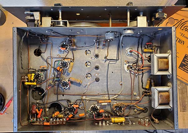
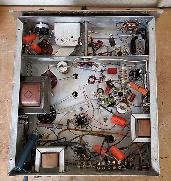
Assembly Removal - In order to correct the problems involving the RF amplifier, the Mixer and the LO circuitry, I'm going to have to remove the Band-Switch/RF Coils assembly. Most of the front-end circuitry is covered up and inaccessible when the Band Switch/RF Coils assembly is installed. Removal isn't too involved but, naturally, when the hamster-rework was performed, this assembly was left in place. This resulted in some of the accessible parts being replaced with wrong value parts that were sloppily installed. But, the remaining capacitors (the inaccessible ones) in the front end appear to be originals. Inspection is required and that will involve dismounting the Band Switch/RF Coils assembly. Removal of the assembly has six braided wires from the tuning condenser, the two antenna input wires (Ant and Dipole,) B+ wire, two wires to the RF amplifier tube socket, a replacement JAN 27K 2W resistor to the LO tube (incorrect value, of course, should be a 10K BED resistor,) four ground wires that are soldered to the chassis,...plus two screws and the switch shaft 
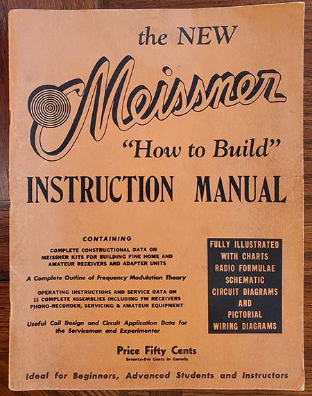
bushing nut and lock washer. Although, the wires are shown on the schematic and shown in detail in the Meissner booklet "How to Build," I made another sketch of just the front-end connections to ease the reinstallation. With the front-end dismounted and out of the chassis, now it's very easy to see what needs to be done here first.

Replacement Capacitors - The original paper capacitors were Meissner brand so almost all of the original shells are long-gone. I checked to make sure I had all of the required capacitors in polyfilm types (yellow jackets) and I did. Initially, I thought about just painting the yellow jackets and not bothering with the shell stuffing since I'd have to find 23 matching shells. But, the more I thought about it,...this Scout is so complete and not physically modified and it will have an original circuit when I'm through with the rebuild so it should probably look as authentic as possible. It would be a shame to NOT do the capacitor stuffing (an OCD moment.) I checked the junk box C-shells and I have the necessary (14)-.05µf, (8)-.01µf and (1)-.005µf (but this shell is going to be marked .006µf.)

Wires - The written assembly instructions indicate that the wire supplied had rubber insulation but the wire in this Scout is solid 22ga wire with cloth insulation. The color codes do match the assembly drawing and schematic. These definitely are the original wires but apparently sometime during the Traffic Scout kit availability the wire type was changed to rubber insulation. Actually, the cloth insulation survives time and environmental conditions much better than rubber insulation that tends to dry-out, crack and fall off of the wire.

Resistors - The original resistors are B.E.D. code and are the type with the wire-wrap around each end for the leads. I have lots of these types for replacements for the originals that have drifted and for the new-types that are installed. The dissipation shown on the schematic and assembly drawing seems low for the physical size of the resistors but I think that's just the operating temperature specs of the time. I used as close as possible for the physical size for the vintage resistors.

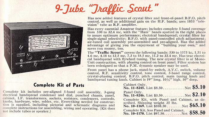
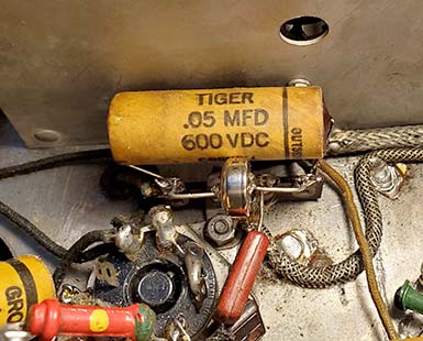
Documentation Conflict,...or is it? - This is minor,...the schematic for the Traffic Master Tuning Unit shows that the LO plate voltage bypass capacitor is a .05µf 400vdc paper cap. The schematic for the Traffic Scout receiver shows the same capacitor as .01µf 400vdc paper cap. I can't reference the original capacitor since it has been replaced with a molded-type of capacitor but,...the replacement is a .01µf cap. So, which value is correct? The Traffic Master "Tuning Unit" is a complete chassis assembly with tubes, tuning condenser and the Band Switch/RF coils assembly. The Traffic Scout, on the other hand, is only the Band Switch/RF Coils assembly mounted under the receiver chassis with the tubes and tuning condenser mounting on top the main receiver chassis. I suspect the Scout schematic is probably correct and the value was originally .01µf (there was also a resistor value change and this is because the Traffic Master used a regulated +150vdc B+ in the LO screen and plate and the Traffic Scout uses an unregulated +200vdc B+.) As mentioned, this component is only a B+ bypass, so its value isn't critical. 


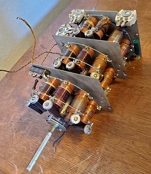
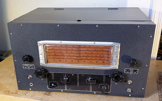
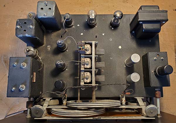
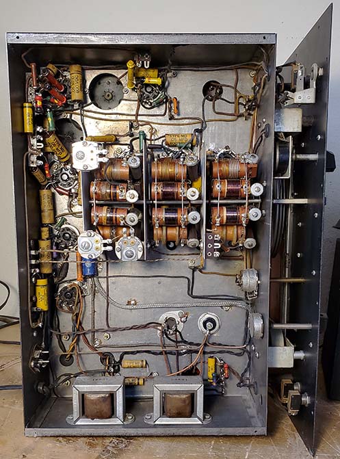
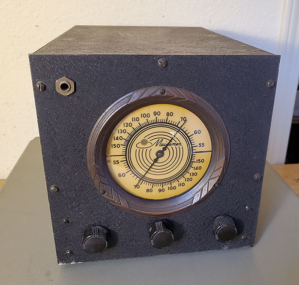
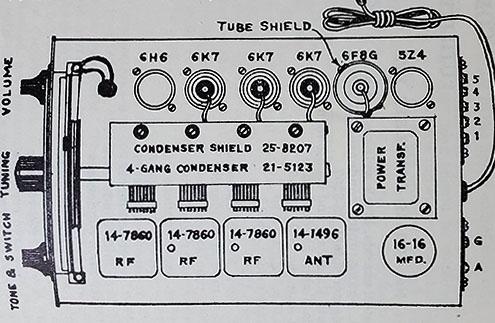
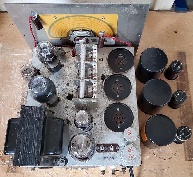
Meissner Traffic Scout - Band Switch/RF Coils Assembly
It's easy to see that the BC band coils are at the left side as shown here and a clockwise rotation of the band switch connects the progressively higher frequency coils going clockwise. Only Bands 1, 2 and 3 have LO padders (the three lowest frequency coverage bands.)

Component Stripping Out and Wire Check - Dec 1, 2023 - I started removing all of the more modern types of components that were installed. This included all of the orange drop capacitors and the JAN-type CC resistors. I also removed the vintage Meissner paper capacitors that were still installed. Almost ALL of the components were unsoldered and removed. This is an interesting process because it let's you find things that have gone unnoticed since the receiver was built. For instance, the cathode bypass capacitor on the RF amplifier was not soldered. I found two other original components and one wire that were not soldered since the initial construction. These weren't obvious because the solder wasn't flowed correctly to allow it to make it to the bottom wrap on the terminal. It's very hard to see the "bottom wrap" but when you're doing a "disassemble" these types of assembly mistakes are sometimes found. Most of the newer parts were just "tack soldered" which made disassembly easy but tack joints are prone to cracking. I also found several cold solder joints on the newer soldering. After removing almost all of the components, I used solder wick to clean the tie-point terminals and tube socket terminals to make sure that reinstallation of the original components and original-type components goes easily and solder can flow easily (because of the "tinned" nature of terminals.) This now left the receiver chassis with just a few of the "tested good" original resistors and the wiring.

Removal of the majority of components was to allow concentration on the wiring and how it's installed. This is part of "lead dress" and it's an important part of correct assembly. Not following the shown lead dress can cause unwanted coupling problems that can cause hum modulation or even oscillation. So, the wiring has to be checked first. I found that eight wires were entirely missing. I'm sure this wasn't from the original building but was the later modification of the audio and standby circuits. To make sure that I checked every wire, I marked the assembly drawing (a copy) with a check mark as I proceeded along. There were two indications of earlier failures. One was the burn mark on the chassis under the LO plate load resistor location indicating the original part had probably burned up. Also, there was a lot of melted wax around the IF screen bypass capacitor location. Of course, both the capacitor and the screen load R had been replaced with newer components. These are just indications that the receiver saw many hours of use when it was new.

Tight Wraps and Poor Assembly Habits - The original assembler probably assumed that his receiver would never be taken apart. Each wire wrap on each terminal was wrapped completely around twice (and wrapped really tight) before soldering. This makes any disassembly very difficult. This same "over-wrapping" habit applied to the components too. One full wrap is more than enough and modern practice is to use only a half-wrap (saves solder and weight on complex in-flight electronic assemblies.) The original assembler also had another bad habit,... every original Meissner capacitor was installed so the value was "face down" and couldn't be seen for visual double-checking of the assembly correctness. Interestingly, even the BED resistors were installed so the multiplier dot was "face down" preventing easy visual checking of the value. This is something that professional electronics assemblers are taught not to do, values of the components always have to be visible so the assembly can be inspected before proceeding to Final Test,...or at least, that's the way it was supposed to be. Of course, amateur assemblers rarely were professionals, so finding examples of these poor electronic assembly habits is common in homebrews and kits.

Some New Vintage Wires - Dec 2, 2023 - Once the existing wiring was verified correct, I could go ahead and install the missing wires. The wire in this Traffic Scout is "push-back wire" and that is solid 22 gauge TC with a loose cloth insulation that can be "pushed-back" so stripping the insulation usually isn't required. But where to find this type of wire? I didn't have any NOS "push-back wire" so I was going to have to harvest what was needed. I found a real junker SX-28 chassis that had been absolutely stripped of everything except the wiring harness. Hallicrafters used "push-back wire" in this chassis. I removed most of the front and left-side harness to end up with the longest lengths of wire. I ended up with a good selection of 22 gauge solid wire TC with insulation colors that were close to what was in the Traffic Scout. Three wire runs were very long (>16") and for these I had to splice two wires to get the length I needed. I had noticed that a couple of the original wires were spliced and appeared to be splices from when the kit was built (probably correcting wiring mistakes.) I made my splices appear similar to these vintage splices using black friction tape for covering the soldered splice. The eight missing wires were two for the B+ and the 6V6 plate connections to the phone jack. These wires mute the audio to the loudspeaker when the phones are used. Two wires to the Remote Standby terminals. These two wires parallel the front panel Standby switch but with these wires missing a T-R relay couldn't be used to place the receiver into standby. Two wires were missing that connected to the Loudspeaker socket. Don't know why these were missing. Maybe the last rebuilding project was never finished. Two more B+ wires were removed to allow jumping the B+ routing because of the disconnected Remote Standby terminals. This was a minor modification that a former restorer incorporated rather than connecting up the Remote Standby terminals correctly. All of the replacement wires look acceptable. They don't match exactly but they are close enough.

photo left: Top of the Traffic Scout chassis looks pretty good and this was before any rework. Note Meissner's signature black wrinkle finish paint on the chassis. Also note, the Crystal Filter and the BFO are assemblies in shielded boxes. The BFO assembly has the 6SJ7 tube mounted on top of the shielded box. Note the GT-style tube for the audio output and rectifier. Also, the LO tube is a metal 6J7 where Meissner calls for the glass version, 6J7G. Also, note that the two IF amplifier tubes are glass GT tubes where these tube should be the metal versions, 6K7. Note that the shaft from the BFO coupler is a white nylon shaft,...not original, of course.


photo right
: It was a different story underneath the Traffic Scout chassis. The photo was taken with the Band Switch/RF Coils assembly removed. The replacement orange drop capacitors can be seen and these are all incorrect "100vdc rated" capacitors. There are eight original Meissner paper-wax capacitors still in the circuit. Note that the original resistors are the "dog bone" style with the B.E.D. color code for value. The electrolytic filter capacitor nearest the front of the chassis is the wrong value and the wrong style. That resulted in the filter wiring being routed differently and looking incorrect.
Resistors - Dec 3, 2023  - With the missing wires now added into the circuit, the resistors could be reinstalled. I used either the original-tested good resistors or the same style resistors from my vintage resistor collection that tested good. Despite the fact that the resistors (in the style needed) were NOS vintage resistors that had never been used, being carbon resistors, the values are prone to drift. I also had another box of the same style vintage resistors that were used "pulls." The interesting thing was that almost every resistor tested in the NOS box had drifted in excess of 50% of value. I found a few that were good but most were unusable. Just the opposite was found in the box of "pulls." Almost all values needed tested within tolerance. Between the two boxes I was able to find the values needed although sometimes I had to use slightly larger so called 1/2W (in that style) instead of the original 1/4W rating. When finished all of the resistors look like they could be original to the receiver which was the intent. Also, the values are within 20% of spec which was the original tolerance.

Rebuilding Capacitors - Dec 5, 2023 - This IS a lot of work but it results in the circuitry looking very original even though all of the paper-wax capacitor shells are actually "stuffed" with polyfilm capacitors. The first step is to melt out the cores from the original shells. I use a heat gun for the procedure. As the cores are removed, while still hot, the shell is wiped down with a paper towel to remove excess wax. This leaves the shell clean and new looking. The easiest approach is to melt out ALL of the cores first to have all of the shells prepared for "stuffing." The melting-out process takes about 30 minutes to do 23 shells. Eight of the shells are from the original Meissner capacitors that were still in the Scout, so these will be going back into the receiver with new polyfilms inside. Incidentally, I always do this melting process outside because it is messy with melted wax being blown around by the heat gun. Also, the smell of the melted bee's wax is avoided if the process is performed outside.

The next step is to install the polyfilm caps into the shells. I use masking tape wrapped around the polyfilm so that the fit into the shell is tight enough that the polyfilm won't fall out. Capacitor count for the Band Switch/RF Coils assembly is (3).05µf and (1).01µf. For the chassis, (1).1µf, (7).01µf and (11).05µf. Total polyfilm capacitors is 23. There are also 3 electrolytic filter capacitors and 1 cathode bypass electrolytic.

Next, hot-melt glue is used to fill-in each end of the shell to seal up the re-stuffing process. The hot-melt glue is slightly yellow but almost clear when it sets up. I use a brown Sharpie to color the hot-melt glue a brownish color that looks more like the sealing wax that was originally used. I normally rebuild all of the capacitors first to have them all ready for installation. For some reason it seems like the installation goes faster if all of the rebuilt capacitors are ready to use at the beginning of the task. The rebuilt capacitors have to be installed carefully per the assembly drawing. Physical orientation and positioning of the capacitors is part of the lead-dress and should follow the drawing exactly. Finished the rebuilt capacitor installation on Dec. 7, 2023.

Refurbishing the Band Switch/RF Coils Assembly - The final components were the rebuilt capacitors located inside this assembly and while installing these I noticed that the non-original Mixer bypass capacitor that was a plastic molded cap was installed with the outside foil not connected to chassis. I can see why this happened and the problem is the Meissner assembly drawing that doesn't show the outside foil on the capacitor drawings. Usually there's not too much confusion since most of the bypass capacitors will be connected "outside foil to chassis-ground." There are some coupling capacitors in the audio section but normally the outside foil is connected to the low impedance side of the circuit. The rebuilt Meissner cap was installed to be visually correct but with polyfilms there really isn't an outside foil so the actual position doesn't matter (I orient all of the polyfilms so that if the nomenclature is rightside-up then I consider the left lead as the outside foil. This is just to keep the installation consistent with all capacitors in the same orientation,...I know, OCD.) I've also checked the two 100K resistors in the assembly and they are well-within spec. I cleaned the dust out of this assembly and used a small paint brush to apply some DeOxit to the switch contacts. The assembly was then ready to install.


Traffic Scout Chassis Finished

Installing the Band Switch/RF Coils Assembly - It's easier to install this assembly after all of the rebuilt capacitors are installed in the chassis. Some of the chassis capacitors are actually under this assembly when it's fully mounted so this installation has to be performed after the main chassis rework. The capacitor that bypasses the bias cell had to be removed as it interfered with the back plate of the BS/RFC assembly,...luckily, I hadn't soldered it in place yet (I was still working on a bias cell solution.)

There are several connections that have to be soldered after the BS/RFC assembly is bolted in place. There are three flex connections to the tuning capacitor stator and three flex connections from the tuning capacitor rotor. Two connections to the RF amplifier tube, two connections to the LO tube, one B+ connection, Antenna and Dipole connections and four TC wire grounds,...seventeen connections total. I double-checked all of the connections and did find one LO mica capacitor that I hadn't flowed the solder all the way to the bottom, so that's a common problem that should be checked and double-checked on all kit electronic assemblies.

The finished chassis is shown in the photo to the left. Most of the capacitor shells I used were Cornell-Dublier Type MD or TIGER types but the slightly brighter yellow shells are the original Meissner shells. Four of the Meissner shells are inside the Band Switch/RF Coils assembly. The electrolytic filter capacitors are close to the original appearance and value. The under chassis appearance is close to original,...or,...I should say, as shown on the assembly drawing.
Making the Bias Cell - I used an Energizer #357, 1.5vdc battery-cell. These are about .375" in diameter and about .250" thick. I used a diamond file to clean a small area on both the positive and the negative sides. You just need to break-through the plating so it's just sort of "roughing" the area for about .125" diameter area. Using a 25W soldering iron, I tinned the "rough" areas on each side with solder. I only applied heat long enough to melt the solder,...about three seconds. I then made two 1.5" long 22ga. TC leads with a short bend on one end (about .060" bend.) The bends were then tinned with solder. Then holding one TC lead with needle nose pliers, I placed the bend next to the "rough" spot and melted the solder on both the lead and the "rough" spot. I repeated this for the other TC lead and the other "rough" spot. Apply just enough heat to melt the solder and then stop (about three seconds.) I checked the voltage of the bias cell and it read 1.59vdc as it had before. This approximates what the original bias cell looked like and solders into the circuit in the same manner as the original did. Proper polarity must be observed when installing the replica bias cell (the negative is connected directly to the 1st AF amplifier grid-cap lead at the tie point under the chassis.) The easy part of "making" the bias cell is that whenever it needs to be replaced (after a long while, hopefully,) it only takes about 10 minutes to make one out of a #357 or #303 cell,...and these batteries are very, very easy to find at just about any store.


Bias Cell Installed

Vintage Power Cord - I went ahead and replaced the crappy-looking brown plastic zip cord with the molded plug (probably harvested from a cheap extension cord.) I used a vintage black rubber AC cord that looked appropriate and, although it had a molded plug, the plug was actually a vintage molded rubber plug.

Band 4 and Band 5 Overlap - It's interesting that the two highest frequency bands have a significant overlap. Band 4 covers 7.3mc up to 18.5mc and Band 5 covers 11.2mc up to 32.4mc. Overlap is about 7.3mc (11.2mc to 18.5mc is covered on both bands.) This ends up with the user able to tune 20M on either Band 4 or on Band 5. Band 1, Band 2 and Band 3 don't have any significant overlap.

Dial Lamps - These two lamp sockets are held into the dial assembly by pushing the lamp through grommet-lined holes. Being rubber, the old grommets were dried-out and brittle and broke up almost immediately upon dismounting the lamps. No problem, I installed new grommets. Then I saw that the lamp sockets were the type that had rubber insulation inside the socket. This had to be chipped-out in order to dismount the old light bulbs. I removed all of the old brittle rubber and replaced it with small wraps of friction tape. The light bulbs were then installed into the sockets and then pushed into the grommet-lined holes. Dial illumination checked and it's okay.

Tubes - The two IF amplifier tubes were glass 6K7GT tubes so no shielding on the IF amplifier tubes that can easily oscillate unless shielded although the Meissner catalogs indicate that their IF transformers were designed to help prevent IF oscillation. I replaced the glass tubes with metal 6K7 tubes since that's what is shown in the Meissner instructions. The 6Q7 duplex-diode triode was so weak it barely moved the TV-7 meter (might have been due to the lack of the bias cell.) The 6K8 and 6SJ7W tubes both tested good. The 1853/6AB7 tested about 50% of minimum acceptable so it was replaced with a NOS 6AB7 tube. The rectifier tube is supposed to be a 5Y4G but a 5Y3GT was installed. Internally the tubes are basically interchangeable but the base connections are different. Sometime in the past, the rectifier socket wiring was changed to accept a 5Y3GT. I rewired the rectifier socket back to original and installed a good 5Y4G tube. The LO tube is shown in the docs as a 6J7G (glass envelope) with no shield. The RCA tube manual shows no difference between the glass or metal versions other than the envelope. The only reason for the glass version might be heat versus LO stability. The glass envelope will run cooler, especially without a shield. Same for the 6V6G versus the metal 6V6 version. For the entire tube compliment, I ended up installing two tested-good 6K7 tubes, one NOS 6AB7, one NOS 6J7G, one tested good 6V6G, one tested good 5Y4G and one NOS 6Q7.

More on "G" envelope glass tubes - Audiophiles have driven the prices up on almost all glass tubes, especially "G" envelope tubes. I was totally surprised when I checked the price being asked for 6J7G tubes, a very common sharp cut-off pentode, nothing special,...or so I thought. The lowest price was about $30 with some foreign "audio tube dealers" asking TEN TIMES that amount. Of course the metal version, the 6J7, is usually under $10 (and that would probably be for two of them) or the 6J7GT (short, squatty, cylindrical glass envelope) at about $12 each. Why the fascination with the "G" glass envelope? Whatever you do, don't ask an audiophile. Descriptions from "sweet sounding" to "wonderful transparency" (or some other similar description of their aural rapture) will result. It's obvious that it's the visual appeal of the "shouldered shape" that's desirable and nothing else. Now,...glass tubes do run cooler than their metal counterparts. If the glass tube is shielded, that shield is usually quite large, with lots of holes, so the heat isn't held inside,...like it is with a metal tube. Does it matter? It depends on the tube's function in the circuit. Usually, receiver front end tubes aren't "pushed" and they tend to run fairly cool so metal tubes can be used in the front end without any heat problems plus the shielding provided is normally required anyway. Audio output tubes and rectifier tubes are "pushed hard" and they do run hot. Almost always, these tubes must be glass versions for tube-life longevity. The "G" envelope, with its larger proportions, will tend to run slightly cooler than the "squatty" GT-type glass envelope. In reality, the unshielded "G" envelope appeal is probably 25%  heat factor and 75% visual appearance.

IF Transformer Shield-Cans - These were both dented on top and the top mounting screws were "pushed in" and bending the metal. The output IF transformer was missing all of its paint on top. The shield-cans had to be removed in order to "body work" the dents out. Nuts under the chassis secure the cans and then the nuts on top secure the IF transformer itself to the can. All of the nuts have to be removed to take off the cans which leaves the IF transformer in place being supported by the wire leads. The can material is very soft so once dismounted the dents were easy to push out with a wooden tool. I added an extra 6-32 nut on the trimmer assembly on each IF transformer to have the outside nuts tighten  against these nuts rather than the ceramic trimmer assembly. I painted the tops of the cans with Mars Black acrylic which can be textured to look something like wrinkle finish. Additionally, the grid lead on the output IF to the 2nd IF amplifier tube needed to have the grid lead replaced. It was the only grid lead with a rubber insulation and the rubber was dried and falling off. Once the can was off, I could see that this rubber wire was original, so the replacement grid wire was also a green rubber insulated wire. I harvested the natural rubber insulation from a slightly-older power cable (from about a decade ago) since these types were still using natural rubber for insulation and three conductor cables will have a green insulated ground wire. Once all of the IF can work was finished, the cans were remounted to the chassis.


Traffic Scout Top of the Chassis after Rebuild
To have the chassis appear as it would have in 1941-42, I installed "G" envelope tubes where glass tubes were specified. I didn't clean the chassis other than "dusting" because the winkle finish paint is prone to "flaking off" quite easily.

"Traffic Scout" - Power-up

Power-up Turns Up One Bad Component and One Mistake - Dec 10, 2023 - I was at the point where I could do an operational test on the Traffic Scout. I used a loudspeaker from an old pre-WWII HRO since this loudspeaker had a 7000Z output transformer inside the cabinet. I connected an inside 50' wire for the test antenna. Right-away, as soon as just a little AC was applied (using a Powerstat) I could hear AC hum. The electrolytic capacitors seemed to test okay but maybe 8uf is insufficient and 30uf is needed. I "clip-lead" connected a 47uf 450vdc electrolytic in parallel with the old cap which isn't something that should be done. It's okay for for testing but I'll be replacing the input filter (I later cut the leads from the 8uf and temporarily "tack soldered" the 47uf in place to allow more testing.) I tested the B+ and had around +250vdc which is correct. With the power supply now functioning, I still didn't have any signals, just audio noise. I injected a 400hz audio signal at the grid of the 1st AF amplifier and that produced a strong signal. Injecting a 456kc mod at 400hz to any grid in the IF or Mixer sections didn't produce anything. In changing the levels and raising the mod F to 1000hz, I could hear a slight signal. I checked the voltage levels in the IF section and they were okay. Then I double-checked the components,...I had the screen bypass cap on the 2nd IF amplifier connected to pin 3 which is the plate connection,...oops. That'll sure take all the signals right to ground! Well,...the screen was on pin 4, so that was pretty close for a septuagenarian assembler like me. Moving the screen bypass cap to pin 4 resulted hearing the 456kc mod 1000hz signal quite well. I touched up the IF transformer alignment and that improved the signal a lot. Lots of background noise and I tuned in several AM-BC stations. Audio sounds very good, not Hi-Fi but natural sounding with no distortion. BFO doesn't seem to be working but it turned out that the coarse adjustment was way off and the front panel adjustment wasn't in the proper range because of it. With the coarse adjustment in range then the front panel BFO adjustment worked but seemed to never stay set and had a weird feel to it. See Dec 12th for the fix.  

Tested reception on 40M and heard several SSB and CW stations and a few SW-BC stations also. WWV 10mc quite strong. Tried 20M but really didn't hear much except for the modulated heater blower from the house furnace (indoor antenna is why.) WWV 15mc was very strong. Several SW-BC on the 25M band. Tried Band 5 and surprised that I picked up 17M stations and 15mc WWV. This was before any front end alignment and the IF alignment was just a "quickie" aural-only adjustment. The receiver itself is setting on its side so this isn't the most stable set up. BUT, for a "first test" just after getting it working, it's pretty impressive.

Dec 11, 2023 - I connected the Collinear Array to the Scout and tuned it for 20M. The band was packed with lots of signals. No obvious DX but lots of East Coast stations. I went up to 15.035mc and there was Trenton Military Aviation Weather coming in very strong. Trenton is in Ontario, Canada. Went to 40M but, except for one extremely strong net control signal, there wasn't too much activity. As for Band Spread, it looks like 20M has about 45% of the dial. 40M Band Spread is around 80% of the dial. I haven't checked 80M but I'm sure it will be over 100% coverage on the Band Spread. That would require one setting of the Main Dial to 4.0mc for BS down to 3.7mc and then a reset of the Main Dial to 3.7mc to cover 3.7mc down to 3.5mc with BS. The "spread" allows very easy tuning of CW or SSB signals and the IF passband is pretty sharp - I'd guess about 6kc at -10db or so. AM SW-BC and AM-BC audio sounds very good though the passband selectivity does limit the upper end audio a little but that just makes it sound "mello" in the AM mode.

Weird BFO Feel - Dec 12, 2023 - I noticed that the BFO had an insulated shaft that is a .250" diameter piece of white nylon instead of the correct metal shaft. The nylon gives the BFO adjustment a flexible, rubbery feel. The reason that someone installed the nylon shaft was to have it flex to compensate for the misaligned mounting of the BFO assembly and the original "non-flexible" shaft coupler used. I removed the nylon shaft and then used a long .250" diameter metal shaft as an alignment rod. I then loosened the two BFO mounting screws and by changing the BFO assembly position I was able to have the metal alignment rod easily rotate within the panel bushing. I tightened the BFO mounting screws and then removed and cut the .250" metal shaft to the proper size and installed it into the insulated non-flexible coupler on the BFO assembly and then installed the knob to complete the rework. BFO is now easy to adjust and seems much more stable than before.

Rebuild Input Filter Capacitor - Dec 14, 2023 - Found a proper size capacitor can in one of the junk boxes. It isn't marked for value which is great. Just a part number. The 47µf 450vdc capacitor will fit inside easily. I'll have to make a terminal and lug so that this replica matches what the original 30µf cap looked like. This will require a slight change to the present wiring layout but this layout had been changed from the original to accommodate the non-original can that had been installed (it was the wrong value capacitor, too.) The end result with the new rebuilt input filter capacitor installed is that the underneath of the chassis will look like the original installation. The can was the negative connection on the original filter capacitor. I had to bring the negative lead through a small drilled hole in the bakelite bottom of the new can. Then this negative lead was soldered to the lock washer that is between the chassis and the can mounting nut. I checked with a cap-meter that the mounting was providing good conductivity. 6V6G Cathode Bypass Capacitor - I used a vintage Beaver-brand electrolytic shell for this "stuffing." The rolled-end was unrolled and the original capacitor removed. Then the new electrolytic was wrapped in masking tape until it was a tight fit in the shell. The unrolled end was rolled back in position. Then each end of the capacitor was filled with hot-melt glue. When this cooled, the rolled end was touched-up with a blue felt pen. Then the hot-melt glue was colored with a brown marker. The capacitor was then installed.


Traffic Scout after Restoration

IF and RF Tracking Alignment - Since the Scout has a Crystal Filter, the IF should be adjusted to the crystal frequency for best operation of the Crystal Filter. Sweep the RF Signal Generator around 456kc with the output of the generator connected to the Mixer grid through a 0.1uf capacitor. Have the Crystal Filter in the circuit, BFO off, AVC off and no modulation on the generator signal. The audio output of the receiver will produce a peaked output as the generator output sweeps past the crystal frequency. Note the generator frequency. This is the frequency that the IF should be aligned to. There are several methods for measuring the peak output of the IF. The easiest is to connect a VTVM to the AVC line and switch on the AVC. A negative voltage will increase (go more negative) as the IF transformers are tuned. Once the IF is aligned switch on the BFO and center the knob then adjust the trimmer on the BFO assembly for zero beat. The IF was fairly close to being in alignment. The Crystal Filter crystal checked at 456.3kc.

The RF tracking requires a dummy load of a 200pf capacitor in series with the signal generator output and connected to the antenna input. The 200pf is only used on Band 1 (AM-BC.) For Bands 2-5, a 400 ohm series resistor is used for the dummy load. LO tracking is adjusted first. Bands1-3 have a padding capacitor to compensate for the low end tracking. Use the trimmer for the high end and the padder for the low end. After the LO tracks correctly then the Mixer and RF can be adjusted. Bands 4-5 only have the high end trimmer for LO adjustment.

The RF tracking alignment was way off. Some of the LO trimmers required several turns to bring the LO in agreement with the dial. The Mixer and Antenna trimmers weren't quite as far off. Bands 4 and 5 don't have a padder to adjust the low end tracking. I can see where the factory "pushed turns" to align the low end. When the high end trimmers were adjusted correctly though, everything tracked as it should. Having only one RF amplifier, images can be heard above 10mc if the signal input is strong enough. I kept the generator amplitude very low to avoid mistaking an image for the correct adjustment. Tracking on Bands 1, 2 and 3 is excellent. Tracking on Band 4 has a slight error of about 300kc at 10mc WWV but is exact on 15mc WWV. Tracking on Band 5 is pretty good with the greatest accuracy on the 20M ham band and 15mc WWV (low end of Band 5.)

Performance - The Traffic Scout is a surprisingly good receiver that could have easily been used by an entry-level ham for successful communications with other hams. At the time, nearly all hams were on CW and almost all of the activity for new hams was on 80M. If the new ham was interested in Phone, then 160M was the band that new hams could use. 40M at the time was CW only. Although there were hams on 20M and 10M, 20M was very competitive and 10M was similar to 160M in that new hams could operate Phone there. Operating on 160M, 80M or 40M would have no issues. 20M performance is really very good but images can be a problem at that frequency. On 10M, images are rampant and it might have been difficult to tell exactly which frequency the other ham was actually transmitting on. I did a lot of listening on 20M and heard loads of signals. All SSB signals demodulated without any distortion problems, of course, the receiver has the AVC off and the RF gain greatly reduced. In fact, most of the 20M signals required the RF gain at about 50% advanced for proper demodulation of the SSB signal. CW signals were easily tuned and the vernier effect of the Band Spread made tuning of either CW or SSB signals easy. SW-BC with the AVC on still required some reduction in the RF gain or the receiver would overload and block. This only happened with very strong signals mostly from utilities-type stations sending digital information. 40M was similar to 20M except the signals were stronger and the RF had to be reduced to maybe 30% advanced on some strong SSB stations. The important thing was that these ultra-strong SSB signals could easily be demodulated with no distortion by just reducing the RF Gain. 80M was the same as 40M as far as reception. What I did notice about the Traffic Scout was its amazing audio. Not that it's high-fidelity but there's no distortion and the reproduction is natural sounding even though the IF passband is fairly narrow,...probably about 6kc at -10db. I wonder if the use of a battery bias cell on the 1st Audio Amplifier grid has something to do with it? At any rate, the Traffic Scout was undoubtedly a competitive receiver within its price range back in 1941-42. I don't think it would be difficult to actually use the Scout "on the air" successfully nowadays but it would certainly be dependent on the user's experience with vintage gear and patience with modern reception problems. One thing to note was that my testing was using a very large antenna, a Tuned Collinear Array, so signals were quite a bit stronger than they would have been if I had been using a smaller antenna.

UPDATE: Dec 19, 2023 - Received XSQ on 12.65mc and 12.67mc, China Mainland Maritime Station operates on multiple frequencies. These stations are somewhat difficult to receive. CW ID along with "chirping" digital info.

UPDATE: On the Air - Jan 7, 2024 - Used the Scout as the station receiver for the Nevada Vintage Mil-Rad Net on 75M using the Pixel Loop as the antenna. The transmitter was a Viking 1 on the Collinear Array. Copy was Q5 on all stations except one 25W station that was about Q2. The Scout has a very narrow bandwidth and when AM stations are tuned "on the nose" and one can hear the audio high-end drop off significantly. On the plus side, no QRM. I know that the Scout might respond to the very weak signals better with the Collinear Array but it would also tend to overload easily on the extremely strong signals. Besides, the Pixel Loop is an excellent antenna and the Pixel Loop made the set up with the Viking 1 really easy since no T-R relay was necessary.

Critique - No Receiver is Perfect - While the Traffic Scout is a pretty good performer, I do have to mention a few things that are noticeable albeit minor problems. I think most of the problems are just due to mechanical wear in assemblies that are over 80 years old. The AF Gain control shaft is very long and doesn't have a bushing in the panel for support. This results in the AF Gain control having a very loose and wobbling feel to any adjustment. A panel bushing would certainly solve this problem. The Tuning and Band Spread controls are very "light" feeling with very little resistance felt while tuning. This really isn't a problem after a short period of time "band cruising." The very light action of tuning makes for easy fine adjustments so this is more "becoming accustomed to" the light feel than a real problem. The Band Switch/RF Coils assembly along with the front panel mounting and chassis all have a lot of flexibility that might be the cause of frequency instability problems when any control is adjusted or even touched. Just pushing the front panel will cause a frequency "wobble." Also, the power supply voltage seems to respond to every appliance load that switches on or off the AC line and this causes slight but noticeable frequency changes that match the switching time of the appliance. The AVC is a standard delayed AVC circuit and sometimes it becomes overloaded with ultra-strong signals and that causes the receiver to "block" reception. This only happens with the RF Gain at maximum and reducing the RF gain clears up the blocking. With a large antenna producing extremely strong signals, images are very apparent within the 20M band with WWV 15mc image (14.088mc) being very strong, prominent and easily recognized as an image signal. Sometimes ultra-strong SSB ham signal images will show up outside the 20M band (add 912kc to the image "tuned frequency" for the actual frequency.) Images for 10mc WWV even show up on 9.088mc, which is surprising. This is typical of a single preselection receiver when operating with a large array antenna that provides very strong signals. The image problem could be cured with an external preselector. Meissner made one called the "Signal Booster" (Model No. 9-1031, price was $50.25 in 1942 catalog) as did several other manufacturers. Preselectors were popular accessories around 1940. So, nothing is particularly unexpected in the design or performance of the Traffic Scout. It's a receiver that could have easily been used successfully for communications in the 1940-1950 era. Today, using the Scout as a station receiver would be something that could be experimented with out of curiosity but it probably wouldn't end up as the regular station's vintage receiver.

UPDATE: After using the Scout "on the air" in the AM mode, I found that I had no problem with the AVC or any problems with signals overloading the receiver. Even KØDWC, running 200W at only 1.5 miles away, was no problem. I think the overloading is caused by the extremely strong levels of all signals (and strong noise level) when using the Collinear Array. Using the Pixel Loop (a really good and quiet antenna) worked great with the Scout. So, the Scout can and was used as a station receiver with no problems.


MEISSNER MANUFACTURING COMPANY


DE LUXE SIGNAL SHIFTER
 
The 1941-45 Version of Meissner's famous VFO/Exciter


   Nos. 9-1077 (Grey cabinet,) 9-1078 (Black cabinet,) 9-1079 (220vac) & 9-1080 (Rack Mount)


The Signal Shifter artwork from the 1945 ARRL Handbook

One of the most famous Meissner "ham" products was probably the "Signal Shifter," a low-power VFO-exciter that was self-contained, provided a very stable VFO using a 6F6 tube that was electron-coupled to the Oscillator plate-PA grid input coils of the output section that used a 6L6 tube plus a very-well regulated power supply that used a 5X4G rectifier along with a VR-150 and VR-105 regulator tubes. Each Signal Shifter came fully assembled and they were not available as kits. The Signal Shifter used a set of three plug-in coils for each tuning range, an Oscillator Grid coil, an Oscillator Plate coil and then an Buffer Output Coil (that could also be considered the PA Output Coil.) Each coil set had a part number and there were LOTS of different coil sets available. There was a total of 24 coil sets available in the early forties. Besides the ham band bandspread-type coils, there were 19 General Coverage coil sets that provided continuous coverage from 1.0mc up to 16.5mc. If the coil set used operated below 3.2mc, then the neutralization had to be adjusted but all of the higher frequency coils sets didn't require neutralization. For hams this only affected operation using the 160M coil set. If operation on 10M was desired then there was a 10M coil set available that allowed the Oscillator to operate on 14mc to 15mc and as an output harmonic allowed tuning the 6L6 input to 28mc to 30mc. Each coil set box contained three coils. Ham band coils were $3.00 per set. General Coverage coils were $6.00 per set. There were also coil sets available just for the Amateur Phone Bands for $4.75 per set. These were 1942 prices.
Signal Shifter Evolution - The first Signal Shifters, probably available around 1938, had a round airplane-type dial with an entirely black wrinkle panel and cabinet. The controls were not marked as to their function since it was only a power switch, a pilot lamp and a tuning knob. The earliest versions required a separate power supply (voltages required were intended to be provided by the homebrew transmitter.) These early versions used the same type of plug in coils as the later versions. I had one of these very early Signal Shifters about 20 years ago but was "talked out of it" by the offer of a very nice condition Hallicrafters SX-9 receiver in trade.

By 1939, the "all black-airplane dial" Signal Shifter had a non-regulated power supply that was built-in and this version was then designated as the "Standard Model." Also, by this time, Meissner offered the Deluxe Model that had a silver and black satin-finished aluminum overlay for the front panel, a built-in regulated power supply and a key-click filter. Cabinets were available in grey or black wrinkle finish. These 1939-1940 Signal Shifts had a skirted knob that was vernier-driven by a smaller knob acting on the rim of the skirt. The skirt dial had a 0-100 scale with no illumination. Price in 1940 was $44.95 for the 9-1017 or 9-1018.

The 1939-40 version also had the XTAL-ECO switch (center-bottom - not labeled in the 1940 artwork) that was intended to be used with Meissner's Signal Spotter, a crystal-controlled oscillator (6V6) that was powered by the Signal Shifter's power supply. The Signal Spotter had sockets for four crystals and an optional plug-in thermostatically-controlled oven for the crystals. A 6U5 eye-tube was used to show resonance of the adjustable coupling to the Signal Shifter. Some physical modifications and added components had to be installed on the "Standard" Signal Shifters for them to actually interface with the Signal Spotter (these instructions and parts were included as a "kit" with the Signal Spotter. The Signal Spotter will function correctly by plugging it into the rear auxiliary socket on the back of the Deluxe Signal Shifter which already has these components installed.

The control switch on the right side AUTO-ON-STDBY functions with the oscillator relay inside the Signal Shifter. In AUTO, the Signal Shifter can be controlled by an auxiliary relay within the transmitter that could be connected by a wire cable to the screw terminal strip on top of the chassis. In the ON position, the oscillator or the amplifier is keyed depending on the set up on the rear chassis terminal strip. In STDBY, the oscillator output is shorted to prevent operation but all voltages remain on to allow the oscillator to remain "warmed-up" and ready to use.


Meissner Signal Shifter and Signal Spotter from 1940 ARRL Handbook
The Signal Shifter was available with either a black or grey wrinkle finish cabinet
Model Nos. are 9-1017 (Grey cabinet,) 9-1018 (Black cabinet,) 9-1019 (220vac) and
9-1020 (Rack Mount version.)


DeLuxe Signal Shifter artwork from the 1942 Meissner Catalog

In 1941, Meissner introduced the semi-circular, back-illuminated dial that had a "behind the dial" articulated and illuminated pointer that was projected onto the back of the dial. The face of the dial could be written-on if necessary. Meissner supplied a fairly large quantity of these types of Signal Shifters to the military during WWII. As to the ultimate use of the Signal Shifter during WWII, nothing specific is mentioned in Meissner advertising, although the advertising does imply that the Signal Shifter was used "barefoot" at 7.5 watts output and locations such as Africa, India and the South Pacific are prominent in the ad. Also, a 1945 ad in the ARRL Handbook states that the military had contacted Meissner with a request regarding Signal Shifters,... "Get them back! From your jobbers, dealers and customers. Spare no expense!" From that statement, one could infer that some of the military surplus Signal Shifters were actually pre-WWII models that were provided from civilian sources going through Meissner to the military. Model numbers for this version are 9-1077 (grey,) 9-1078 (black,) 9-1079 (220vac) and 9-1080 (rack.) 1942 prices were 9-1077,78 was $55.00, 9-1079 was $58.50, 9-1080 was $60.00.

The post-WWII Signal Shifter was designated as the Model "EX" and it did away with the rather tedious manual operation of changing three plug-in coils for the different tuning ranges. Now a front panel turret-type band switching was provided. The new type coils plugged into the turret and were strips with the actual coils mounted to the back side of the strips that then mechanically were secured to the turret. The band switch rotated the turret that would then place the selected coil pins into the operating position with contact connections into the circuit. The band switch nomenclature used letters since how the coil strips were installed in the turret determined the frequency coverage selected by the band switch. Six positions were provided, A through F. Also, a front panel crystal socket eliminated the need for the Signal Spotter. A future ham band in the 21.0mc to 21.5mc part of the spectrum had been approved in 1946, so a 15M coil strip was available for the "EX" even though any actual operation on that band didn't commence until 1950. The output tube was changed to an 807 but the output power was actually reduced to 6 watts. The 5X4 rectifier was replaced with dual 5Y3G tubes. The front panel was changed significantly and an eye-tube was provided for resonance/output indication.

By 1952, the Signal Shifter was no longer available (it's not shown in the 1952 Thordarson-Meissner catalog) and Meissner's business focus was also changing since they were now owned by Thordarson-Maguire Industries and had become known as "Thordarson-Meissner."

The most common Signal Shifter found nowadays is the post-WWII "EX" version but a close second would be the military surplus 1942-45 version. Actual pre-WWII versions are much more scarce and the earliest "airplane dial" version is very rare.

Signal Shifter 9-1078 - Operational Notes - During WWII there was a shortage of the metal 6F6 and 6L6 tubes that the original Signal Shifters were equipped with, so Signal Shifters were then equipped with glass tubes, 6F6G and 6L6G, and that required a slight change in the power supply section. The load resistor for the VR-150 tube was a 30K resistor when metal tubes were used. For the glass tube set-up, a 10K resistor was connected in parallel with the 30K resistor reducing the value of the load R and increasing its dissipation. When inspecting a Signal Shifter, if it's equipped with glass 6F6G and 6L6G tubes, the values of R11 (30K) and R15 (10K) should be checked. If metal tubes must be used in a "glass tube" version, then both the 6F6 and the 6L6 must both be metal tubes (you can't intermix glass and metal tubes in the Signal Shifter) and R15, the 10K resistor, should be removed from the circuit. This information is on a label installed on the Output Coil shield and is also printed in the later, WWII-era, instructions.

Though the output was rated at 7.5 watts, it was dependent on the operational frequency and the internal adjustments that are made. Also, the impedance being driven will determine the output power. Years ago, I used my Signal Shifter connected directly to a small Johnson Matchbox which has a "link input" and the output of the Matchbox to a tuned Inv-Vee antenna and measured 12 watts output (on both 40M and on 80M.) It's certainly safe to say the Signal Shifter output would be a minimum of 7.5 watts and it can easily be adjusted to 10 watts output depending on the frequency of operation. Generally, low bands like 160M and 80M will have to highest output and the output is reduced as the frequency is increased above 10mc (20M, for instance, will have noticeably reduced output capabilities.) Around 2000, I worked a Colorado ham on 40M CW and an Arizona ham on 80M CW using my Signal Shifter "barefoot." The CW note is very stable, no chirp and the frequency drift is "minimal" on 40M or 80M. Using jumpers on the back terminal strip either oscillator-keying or amplifier-keying can be selected. Keying the oscillator generally works best with the least amount of "blooping." The 6L6 is biased off until the oscillator is keyed.

Of course, the popular moniker "Signal Drifter" might indicate that the "minimal" drift should be compared to other Signal Shifter contemporaries (1940 oscillators.) Nowadays, "absolute zero-drift" is expected and the Signal Shifter will come up far-short for that type of demand for frequency stability. There were also some experiences reported when using the Signal Shifter as a QRP transmitter it would create lots of TVI. Again, when the Signal Shifters were new, there wasn't any TV broadcasting except for limited broadcasting in some large cities. These later TVI experiences were from young hams in the 1960s that found second-hand Signal Shifters cheap (or free) and then put them on the air usually coupled directly to the antenna,...and this was in the days of wide-spread "over the air TV Broadcasting" with a multitude of rooftop TV antennas in the immediate neighborhood. With no suppression of harmonics, TVI was inevitable, especially in "fringe" areas for TV reception. The switch to cable-TV eliminated most of these problems and when HDTV moved the entire TV Broadcasting to higher frequencies, harmonic TVI became a thing of the past. I used my Signal Shifter with RG-58U connected directly to a Johnson Matchbox acting like another tuned circuit between the output and the antenna. I didn't experience any TVI but I was on cable at the time.


Meissner post-WWII "Model EX" Signal Shifter
This "EX" is shown in the grey cabinet
Interestingly, 15M coils were available for this version of the Signal Shifter. Although 15M had been designated as a future ham band in 1946, actual operation on the ham band didn't start until 1950. The Model EX used an 807 as the output tube but the power output was reduced to just 6 watts.


Meissner DeLuxe Signal Shifter 9-1078 from 1942
Although all of the general coverage coil sets are stamped with a Signal Corps acceptance stamp on the boxes, I can't find any mil-stamps on the Signal Shifter.

Finding the Meissner Signal Shifter 9-1078 - About thirty-five years ago, my old friend W7IND Bob Kirk was handling an estate sale that consisted of a lot of surplus electronics gear that had belonged to W6OHM. The sale was in Carson City, Nevada at the last QTH of W6OHM. Bob called me and wanted me to come over (I lived just south of Carson City at the time) and look at the gear and to also provide some input on pricing. Bob was holding the estate sale in the OHM garage and it was packed with gear. It seemed that W6OHM had wanted to go into the surplus electronics business after he retired and had acquired a rather large inventory of gear and parts. He planned on the business being a joint endeavor with his son. However, the son wasn't the least bit interested in the idea and that left OHM "stuck" with all of this gear he had acquired. So, now SK, OHM's gear was being sold by W7IND for OHM's estate. There were lots of parts and assemblies but very few complete radios, receivers or transmitters. Pounds of Teletype paper rolls, though. A very nice complete pantograph machine. Things like that. I asked Bob about the Meissner Signal Shifter since it looked complete. I couldn't pass up Bob's price of $8,...and that included about a dozen boxes of Signal Shifter Coil Sets. As punishment (and when I wasn't looking,) Bob loaded up my car's truck with lots and lots of Teletype paper rolls. When I got back home, I didn't do much with the Signal Shifter because I didn't have any documentation on it (this was way before the Internet.) A few years later my old friend, K6QY sent me a copy of the Meissner paperwork along with another 9-1078 Signal Shifter (this was when practically nobody was interested in Signal Shifters. Come to think of it,...it might still be that way!) The information allowed me to check-out and "fine tune" my original Signal Shifter and I was able to get about 12 watts output into a decent antenna. I worked several states on CW barefoot on both 40M and later on 80M. I gave the second Signal Shifter to KØDWC in Virginia City and we had a two-way CW contact using just our Signal Shifters (I was also in Virginia City by that time.) Though the Signal Shifter can be used barefoot, after an alignment, with a tuned or resonate antenna and can easily be used as a QRP CW transmitter with good results, be sure to let it "warm up" for about 30 minutes before using. That might reduce the "signal drifter" critical response to a minimum. The other possibility for the Signal Shifter is to use it as an exciter to drive a higher power transmitter. All that would be required would be the RF amplifier for higher power CW. And then, maybe a speech amp and high power modulator for AM. Well,...maybe in the future. For now, QRP CW is fine.
Checking Out the Signal Shifter - It's been a very long time since I've powered-up this Signal Shifter. I'm going to have to perform several checks before actually applying power. Since it worked about 20 years ago, I know the wiring is correct so all I need to do is check the components for any indications of deterioration or other changes due to it being idle for so long. The Signal Shifter has always been indoors and this really helps in the preservation of the components. Also, I'll be looking for anything that I missed years ago that might be more apparent this time with a careful inspection.

The first step will be to remove the chassis from the cabinet for a complete visual inspection. Probably 20 years ago I replaced the twisted red rubber insulated wires going to the dial lamps. The natural rubber insulation was dried up and falling off. This version has the glass 6L6G and 6F6G tubes so I'll be able to verify that the 10K is in parallel with the 30K VR-150 load resistor. VR-150 is located between the 6F6G and the 6L6G slightly towards the outside edge of the chassis. Next, a quick-check of the resistors and capacitors. The filter caps were functioning okay twenty years ago, so I'll probably have to reform them. Then a quick check of the tubes, they're probably fine, but I don't really remember checking them. At that time, my tube tester was an old TV-3 military checker, so a recheck with the TV-7 should be performed. I cleaned and tested all of the tubes. All tubes tested good on the TV-7 tube tester.

I removed the chassis from the cabinet to check the circuitry. While I don't remember doing it, I obviously replaced the original paper-wax capacitors probably about 20 years ago. I used good quality "orange-drop" capacitors but, if I was doing the rebuild nowadays, I would have restuffed the original Meissner capacitor shells. The two dual 20µf 450uf electrolytic filter capacitors are original. The 10K resistor is in parallel with the 30K resistor on the VR-150 tube confirming that this Signal Shifter was set-up for glass tubes.

The top of the chassis was very dusty (undoubtedly accumulated in the past 20 years) and very dirty with some type of "old" greasy-film that I obviously didn't clean off when I worked on the Signal Shifter before. So, now the chassis underwent a thorough scrubbing with Glass Plus. I noticed that the two stationary dial lamps were #44 types that draw .250mA per bulb. I changed these to #47 types that draw about .150mA per bulb. There are light shields that are mounted over the bulbs to reduce backlight in the cabinet and direct the lamp light onto the backside of the dial. The articulated dial pointer lamp is a #51 and that's normal for "dial bulbs" since these have the small round bulb for keeping the heat away from the dial. The two stationary lamp sockets appear to not have any mounting holes but they are installed using the panel screws when reinstalling the chassis into the cabinet.

The two electrolytic capacitors have "C" and "6" inside square boxes stamped in orange paint on top of the cans. These could be some type of Signal Corps stamping but they don't look like any acceptance stamps I've seen. But, the orange color is suspicious looking and reminiscent of Signal Corps stamps.


Meissner Signal Shifter - Top of the chassis showing the serial number "I699" and that this one is the "glass tube" version. The coils aren't installed to show how the sockets are unique for the coil function. Coil shields are shown next to the chassis.


Meissner Signal Shifter Under the Chassis
The orange drop caps aren't original of course. If you know what to look for, the 10K is in parallel with the 30K on the VR-150 tube socket for glass tubes.

Coil Sets - Meissner instructions indicate several times that powering up the Signal Shifter without a coil set installed will put a heavy load on the power supply filters and that coils must be installed before AC power is switched on. All three coils required are inside the cardboard box that has the coil set part number shown on the lid of the box. Each of the coils in a set have a unique number of pins so they can only be installed into the correct sockets. The Osc. Grid coil has four pins, the Osc. Plate coil has five pins and the Buffer Plate coil has six pins. Each coil is identified as to its function and its frequency coverage. However, the labels are small round thin cardboard pieces that are glued to the top rim of the coil. It's common to find these labels either missing or hopefully stuck down inside the coil. Individual, unlabeled coils can be identified by the number of pins for their function. The number of turns on the unidentified coil will provide a general idea of its frequency of operation. Some coils will have a part number stamped in white paint around the bottom rim BUT this number doesn't correlate to the actual part number for the coil set (this stamped number isn't in the Meissner catalogs either.) Orphaned coils that aren't identified and aren't part of a complete set are difficult to deal with and are usually relegated to the "parts box."

Power-up - The first thing was to check the 20µf 450vdc filter capacitors. These were "quick tested" with an old Triplett VOM that showed they were okay. I then used an adjustable power supply to do a quick reform on the electrolytics with no problems. Only three of the four capacitors are used. One of the dual filter capacitors isn't connected to anything. Of the three reformed, each had minimal current draw of < 1µA when charged. Next, I applied AC power using a Powerstat and measured the +HV at about +350vdc which sounded about right.

For a quick test, I had a 75Ω 15 watt resistor connected as a dummy load on the link output. I connected an oscilloscope to the high side of the load through a 200pf capacitor to act as an output indicator. I also turned on the monitor receiver (Siemens E311) with a three foot wire as a pickup antenna. I had an output indication on the oscilloscope and could hear the signal on the receiver so the Signal Shifter seemed to be producing RF.


Meissner Signal Shifter Coil Sets
Note that the general coverage coil sets have Signal Corps acceptance stamps on the boxes. The 160M coil set shows the paper IDs installed.

Adjustments - I switched over to a Harrison 50 ohm dummy load. I had the 18-2955 coil set installed covering 3.975mc up to 4.690mc. I had the keying set to have the oscillator continuously on and key the 6L6G. This is accomplished by having 2 to 3 jumped and 4 to 5 jumped on the rear terminal strip. I set the Signal Shifter dial to "95" and with "ON" selected I pressed down on the telegraph key and tuned in the carrier at 4.690mc on the receiver and I saw a large wave envelope on the 'scope. The adjustment nearest the front will set the oscillator frequency so this was adjusted for peak response on the receiver tuned to 4.690mc (later I set this adjustment using a digital frequency counter.) Then the two adjustments by the 6L6 were adjusted for maximum amplitude on the wave envelope. This completed the adjustments. Once adjusted at the high end of the dial (95) using any coil set, the Signal Shifter shouldn't need any other adjustments with different coil sets (although I usually "peak" the adjustments with each coil change.)

Power Output - As a further test, I used a VTVM that could measure RMS voltage using a VT probe. With the VTVM, I measured approximately 24vrms output from the Signal Shifter into the 50Ω dummy load (actually measures 47.7Ω.) By using the power formula P = E²/R (this would be 23.8 x 23.8 = 566.4 divided by 47.7) = 11.87 watts. That sounds about like what I was measuring using a watt meter several years ago running into an inverted vee antenna through this same Johnson Matchbox. The next measurement will be to see how the Drake W4 wattmeter I now have measures the power output going directly to the Matchbox and then to the tuned Collinear Array.

Change the Keying - As I listened to the signal in the E311 receiver I couldn't help but notice that the initial "key down" had a "bloop" as it started and then was okay as some keying of Morse was sent. Each time the keying stopped for a second or two, the start up keying was initiated by a "bloop." I changed the keying to having the 6L6G on all the time (grid biased off) and then key the oscillator. This requires terminals 1-2 jumped and 3-4 jumped. This set up resulted in solid keying with no "blooping."

Antenna Power Output and Harmonics - With the Signal Shifter connected to the Collinear Array antenna through the Johnson Matchbox I could get a perfect match with a 1:1 SWR and just slightly over 10 watts output power showing on the Drake W4 wattmeter. That's pretty close to the calculated power based on the VTVM RMS measurement.

To check the harmonic levels, I had the frequency set to 3.974mc and the RACAL RA-17L was tuned to that frequency with a three foot antenna and the attenuator set to maximum and the preselector set to broadband. The fundamental signal was quite strong. The second harmonic at 7.948mc was still strong. The third harmonic at 11.922mc was pretty strong. The fourth harmonic at 15.906mc was somewhat weaker. Usually, these types of harmonics aren't strong enough to radiate very far. Especially when the output of the Signal Shifter is link coupled through a coaxial cable to the link input of the Matchbox. Then the Collinear Array must be tuned for minimum SWR, in other words, it's not a broadband type of antenna system so it wouldn't be resonant at the harmonic frequencies. Since all of the equipment is within a few feet of each other and the antenna is about 100 feet away it seems that the only way to check the harmonics is to actually transmit a signal and have someone located miles away to listen at the fundamental and the harmonics. That would be the best way to determine just how far the Signal Shifter harmonics actually radiate.

Dec 31, 2023 - I had the Signal Shifter connected to the Collinear Array through the Johnson Matchbox and the Drake W-4 was indicating 10 watts output with a 1:1 match. I called up KØDWC, who is located about 2 miles NE of my QTH. I had him tune in the Signal Shifter's signal on 3.975mc on his R-390A receiver. I could hear the carrier over the cell phone (although the propagation delay through the cell phone connection is about half a second so CW is very confusing since what you send you actually hear slightly later. I had to turn up my local receiver to act as a monitor and try to listen to both my receiver and Chuck's receiver over the cell phone which was just as confusing.) The Signal Shifter sounded very good with a strong signal listening over the cell phone. I had Chuck tune up to 7.950mc (the second harmonic) and tune around several kc up and down from 7.950mc to try to find a signal. Nothing was heard,...indicating that the harmonic radiation is local and can't even be heard at 2 miles distance. I can now proceed to actually try the Meissner Signal Shifter as a QRP transmitter.

Setting Up the Vintage QRP Station - To keep things simple I'm going to run just the Signal Shifter to the Collinear Array. The Traffic Scout will be connected to the Pixel Loop Antenna. No antenna relays necessary with separate antennas. The Pixel Loop amplifier can easily be turned off during transmitting and the RF gain reduced on the Traffic Scout to allow it to be used as a sending monitor. The Signal Shifter would be in "ON" for transmit and in "STD BY" for receive.   More to come,...I'll update when we actually have a QSO.


References:

1. The New Meissner "How to Build" Instruction Manual, copyright 1943. This booklet is 168 pages and contains many of Meissner's radio kits and complete assemblies, providing almost all of the documentation that was available for the models covered. The booklet is shown in the 1939-1940 Meissner catalog, so earlier versions were available. Online there is a copy of the 1952 version but ALL of the earlier models were dropped from this edition. 

2. Meissner Catalog 1939-1940 - Has all of the sales information on the Traffic Scout, Traffic Master, Signal Shifter and many other models. Also, all of the coils and components available. Prices shown.

3. Meissner Catalog 1942 - Has all of the sales information on the last versions of the Traffic Scout, Traffic Master and on the Signal Shifter that was available just before WWII. Info on "Laboratory-built Receivers." Also, all of the coils and components. Prices shown.

4. ARRL Radio Amateur's Handbook 1940, 1945 - Advertising for Meissner kits and models available. 1945 HB Meissner ad has the military "Got to have them" quote about the Signal Shifter.


Online Info:

1. Thordarson Electric Manufacturing Company - Some info about the founder, not much on the company. Company purchase information had to be inferred from advertising.

2. Meissner Manufacturing Company - Very little info can be found. Some info on their "E" awards during WWII. Purchase information had to be inferred from advertising.

3. Maguire Industries, Inc. - Very little info.


Return to Index-Home Page


Radio Boulevard
Western Historic Radio Museum

 Vintage Radio Communication Equipment Rebuilding & Restoration Articles,

 Vintage Radio History and WHRM Radio Photo Galleries

1909 - 1969

- 60 years of Radio Technology -


This website created and maintained by: Henry Rogers - Radio Boulevard, Western Historic Radio Museum © 1997/2024