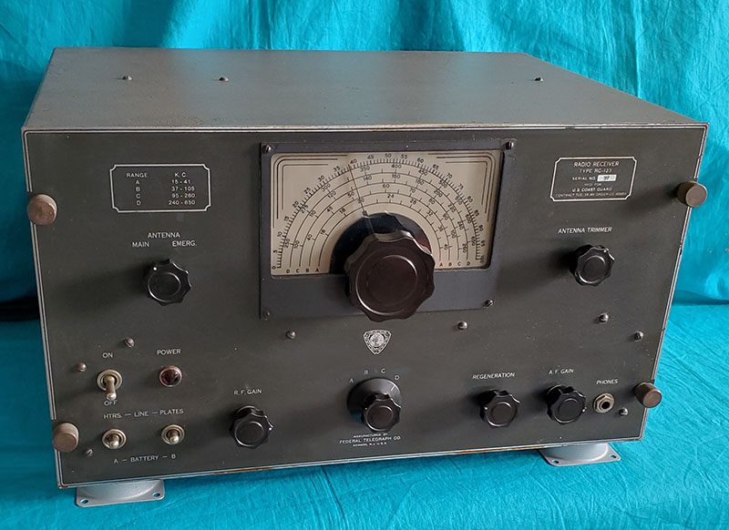
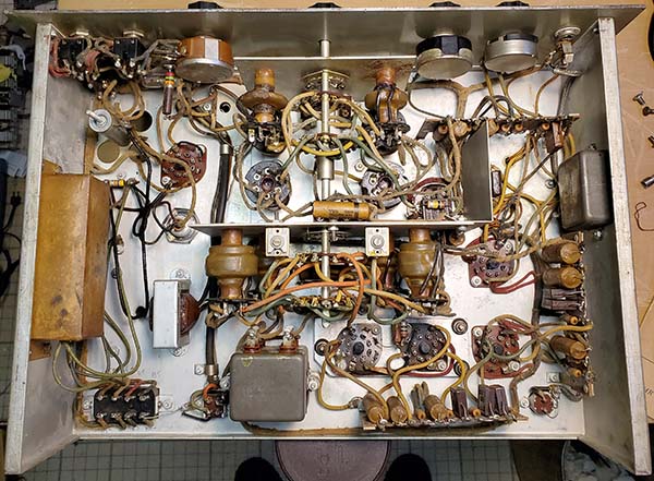
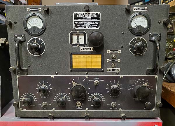
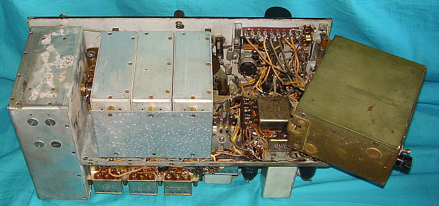
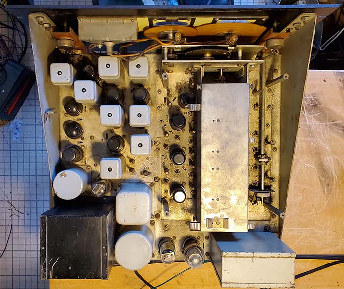
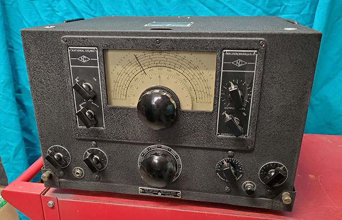
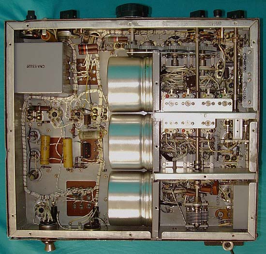
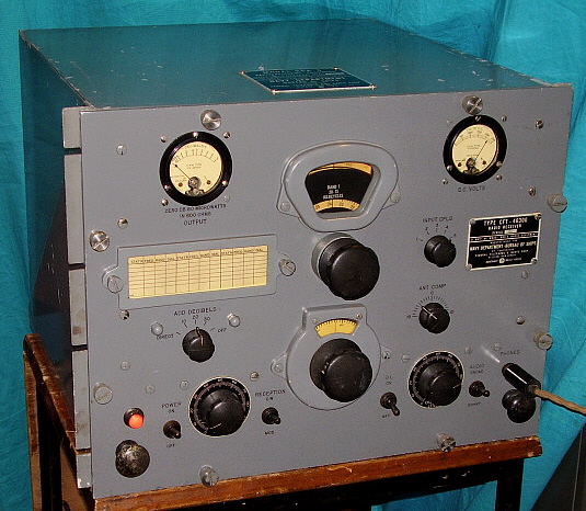
| The RBA-6 shown is from a 1945 contract. This version is
identical to the RBA-5 internally but the RBA-6 is a rack
mounted configuration only and is painted smooth Navy gray
rather than black wrinkle. Judging by the condition of this
receiver, it is unlikely that it was ever put into service. It
is all original except for the substitution of an SO-239 UHF
connector in place of the Navy coax connector for the antenna
input. The RBA-6 is an impressive performer with ample
sensitivity, direct dial read-out with illumination and a
tracking BFO rather than regenerative-autodyne detector. The
tracking BFO actually works quite well for finding the carrier
on weak NBDs. The dial accuracy is excellent and allows tuning
the NDBs by frequency rather than constantly referring to charts
or graphs. The LP filter does limit the audio frequency response
on BC stations but not to the point where the voice is
incomprehensible. The O.L. works quite well at limiting the
maximum output (which is usually due to static bursts) while not
distorting the signal. The RBA-6 is a first-class longwave
receiver capable of receiving any of the signals found below
500kc if used in an RF-quiet area with an appropriate antenna.
RBA-6 Performance
- I have been using this RBA-6 during the morning hours for late
September through most of October 2009 and have found the
receiver to be a phenomenal performer. I can usually separate
LLD 353kc in Hawaii from local Reno AP NDB NO 351kc and this is
using just a wire antenna and not relying on the directional
characteristics of a loop antenna. That's amazing selectivity
for a TRF receiver. I've probably tuned in well over 100 NDBs
but so far only two were new copies and they were West Coast
NDBs. The wire antenna I'm using is the 135' center-fed dipole
with 43' of open feed line that is shorted together at the
receiver antenna terminals. This antenna, while not really
something I designed for LW, seems to work quite well with all
of the LW receivers. Radio Rossii 279kc is received every
morning coming in very strong - Russian LW station located on
Sakhalin Island. JJY also can be received every morning on 40kc
coming out of Japan. Noise is the only limitation on reception
and for better noise reduction I have to run a loop antenna. |
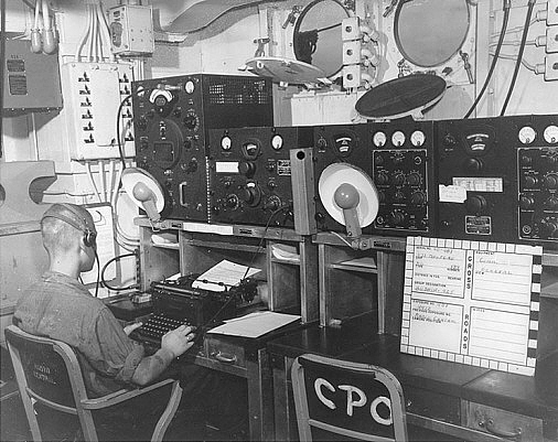
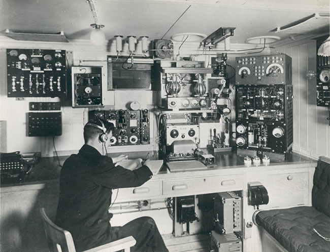
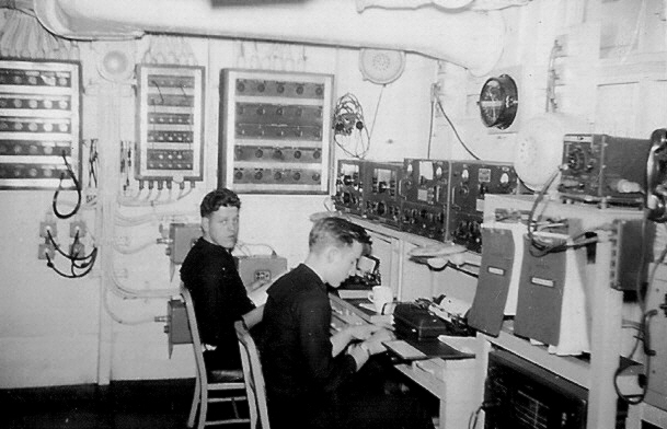
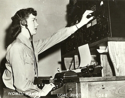
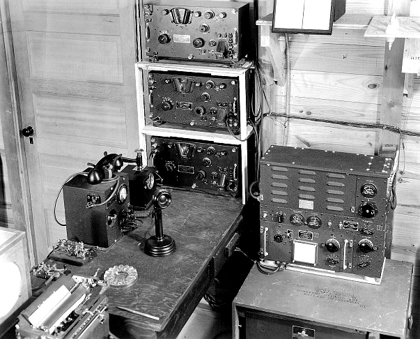
photo above: This USN radio op is
listening to the RBA receiver and is ready to copy on the mill.
Other equipment is the General Radio LR-1 Frequency Meter, the
RBB and RBC receivers. This photo of the U.S.S. Mugford in 1946 |
|
 |
January 21,2010
- I finally got the RBA-6 up to the top floor of the house where
it can be used with the six-foot loop antenna. I had tried using
the loop antenna in the basement but the concrete floor and the
rock foundation were a serious detriment to the loop's
performance. The top floor of the house is actually about 30
feet above ground level and allows the loop to function quite
well even though it is located indoors. The performance of the
RBA-6 on the loop is amazing. The signals just jump out of a
fairly quite background noise level. Much quieter than running
on the wire antenna. Most frequencies seem to have at least
three NDBs active and by tuning the loop I can usually enhance
one or the other to allow copy. Quite an improvement in
performance. November 7,
2013 - QTH is now Dayton, Nevada and the antenna is a
300 foot long end-fed wire up about 50 feet. This antenna works
quite well with the RBA-6 although the noise level is probably
higher than using the loop. However, the actual ambient noise
level is so low in Dayton that the 300 ft wire seems to provide
better signal levels than the loop ever did in Virginia City.
More info to come,... Nov. 8, 2013 0615 PST tuned in JJY at
40kc, very loud signal.
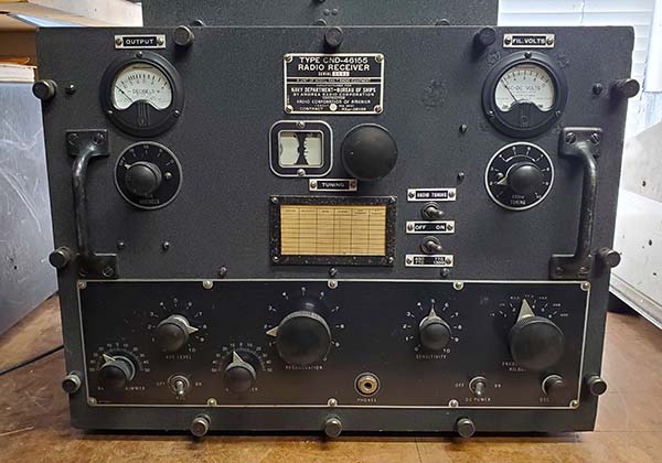
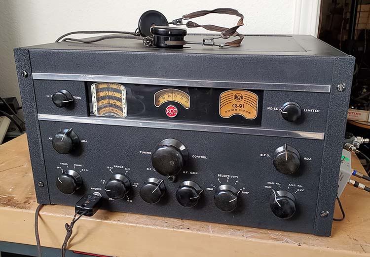
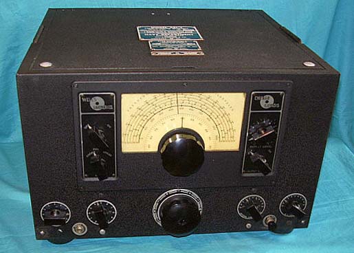
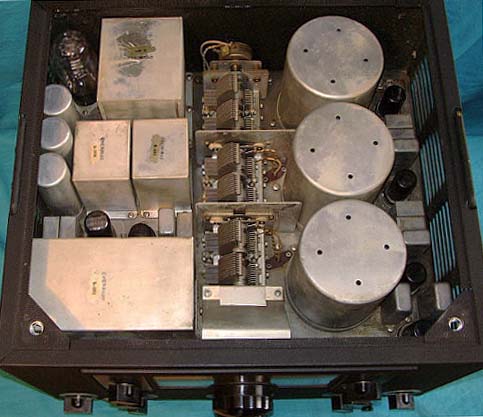
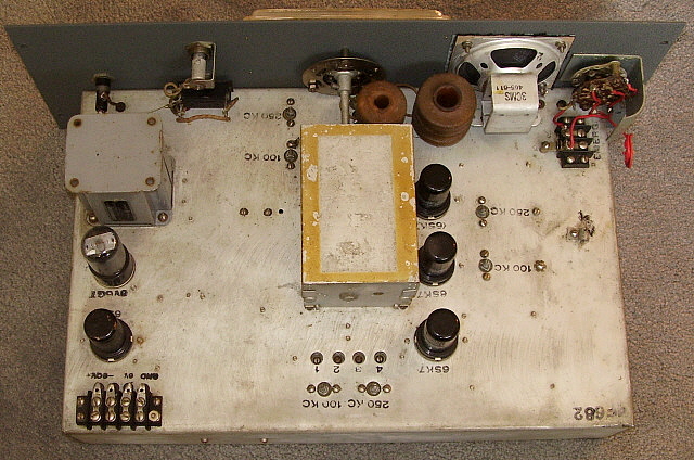
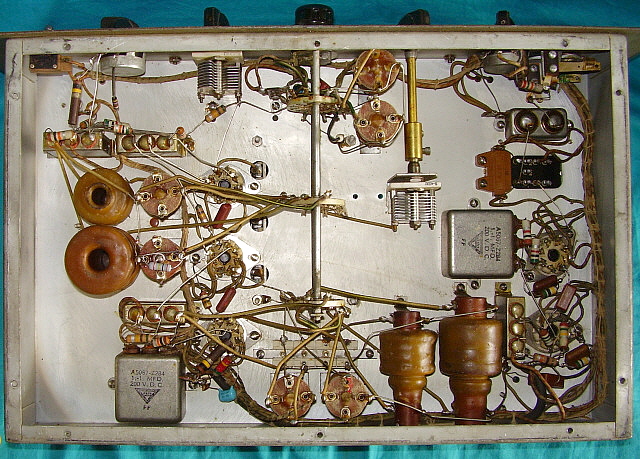
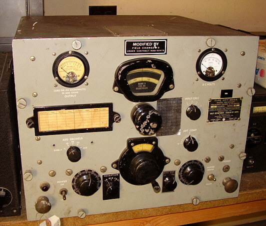
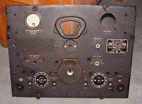
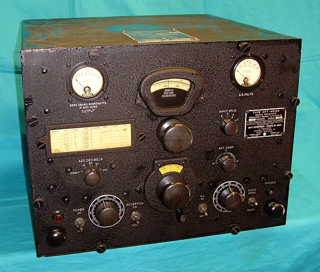
RBA-1,
CFT-46154 - I had the receiver shown to the left
for a short time. It's the early table top version RBA-1, the
CFT-46154. This particular RBA-1 has had a common Field Change
Modification Contract installed that changes the toggle switches
for Reception mode and Output Limiter to knob-type controls.
There are additional changes internally. The B+ meter has been
replaced on this receiver. Additionally, like many receivers
that have gone through a field rebuild, the cabinet is black
wrinkle (it is for an RBA-1) while the receiver's panel has been
repainted gray. This RBA-1 was traded off in 2015. |
|
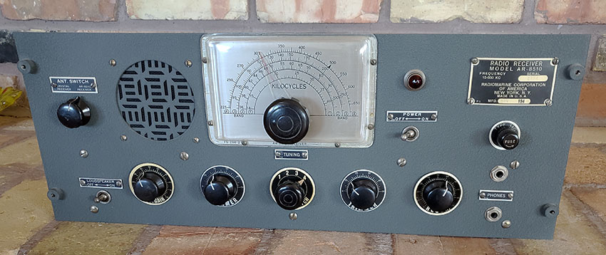
RBA-1 CFT-46154 SN:
972 - Restoration Log |
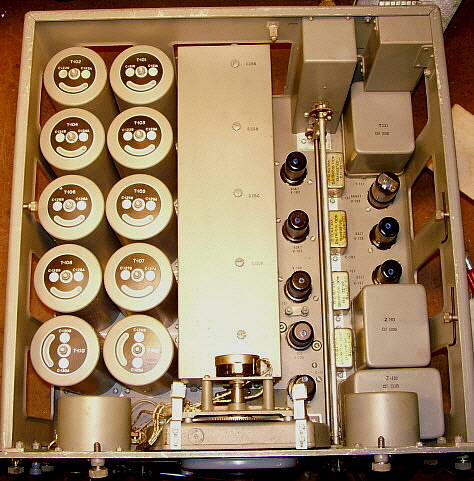
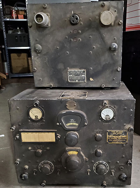
| I acquired RBA-1 CFT-46154 SN: 972 (shown to the
right) from a fellow in Texas in October 2017. It was shipped to
Nevada via UPS. No damage was sustained during transport. I
purchased this particular RBA-1 because it was the first
all-original, black wrinkle finish, complete example that I had
ever come across. Most RBA receivers found around here look like
the RBA-1 shown in the photo above. That is, most have the Field
Change modifications and have been repainted gray. Not that SN:
972 didn't have problems. For example, the DB meter glass was
cracked to several places. The meter, however, worked fine. Band
switching from Band 1 to Band 2 was normal. To Band 3 felt
rough, like fine gear teeth meshing and switching to Band 4 was
stiff but it would switch. All toggle switches seemed to
function okay. There was a little bit of dial drag on the
logging dial which was slightly rubbing against the housing.
Inside was very nice with all shields present. Some very minor
corrosion in just a few locations - nothing serious. Even the
antenna input was still the original Navy coax fitting.
Cosmetically, the cabinet was very scratched up with quite a bit
of paint missing, especially on the top. Front panel was very
good with some minor blemishes and old touch-ups. The dial mask
on Band 4 needs some attention as there are some "pin points" of
corrosion present. All knobs were present but the spinner was
missing from the tuning knob. The two nomenclature panels were
in good condition. All tags were present and in good condition
on both the panel and cabinet. The original tuning chart was
present with NSS (WWII Radio Central USN, Annapolis, MD,) shown
at 18kc. This RBA-1 didn't come with the CVR-20130 power
supply or the armored power cable. Fortunately, I had a spare
20130 and a spare cable to apply power to this receiver.
Normally, I wouldn't apply power without a thorough check out
first, but the seller told me he had the receiver operating, so
there was some confidence that nothing serious was going to
happen. I did check all of the tubes first and ended up
replacing three. I had SN:972 out in the shop, so I connected my
275 ft CF dipole with the 77 ft of feed line shorted to act as
the antenna. Upon power up and warm up, the receiver was
receiving KTHO 590kc up a Lake Tahoe quite loud. I had a 600Z
ohm modified LS-3 connected to the phone jack on the front
panel. Further tuning had MOG 404kc, a NDB from Montegue, CA and
FCH 344kc from Fresno, CA coming in strong. This was about 3PM,
so no DX NDBs were heard. However, when switching to Band 3 the
output was nil, same for Band 2. Switching to Band 1 the
receiver again had output. NAA on 24.0kc was strong but NLK on
24.8kc was extremely strong. NPM on 21.4kc was strong from
Lualualei, Hawaii. So, this RBA-1 is somewhat functional. The
most serious problem is the non-operative Band 2 and Band 3,
however since the receiver works on Bands 1 and 4, the problem
is certainly in the RF stages ahead of the
detector. Additionally, repairing the mechanical issues
of the band switching "roughness" and logging dial drag
will be necessary. The DB meter glass repair will be
accomplished by replacing the entire housing - it's a
Weston Type 506 and they're common. Finally, when fully
functional, a complete alignment. Cosmetics will be
necessary too but that looks to mainly consist of
cleaning and touch-up. |
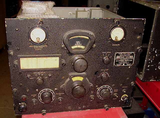
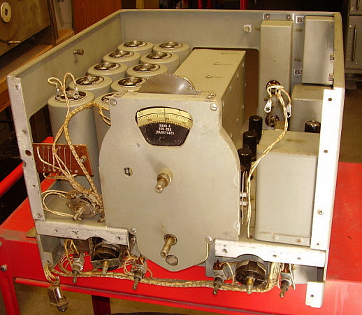
photo above: RBA-1
SN: 972 "as received" Oct. 11, 2017. Note the bubble-wrapped
tubes piled up on the RF coils. Some of the cabinet can be seen
to the right. This photo was taken before the power-up test. |
|
Dismounting the Front Panel - This is an arduous task
that is not well-described in the manual, at least in the
NAVSHIPS 900,708 manual I have. In order to repair the logging
dial drag, the rough feeling band switch and restore the dial
mask, I had to access the cast metal housing that has the dial,
the dial mask and the band switching inside. The only access to
into this housing is from the front and the entire front panel
has to be dismounted to even see the front of this housing. To
get the front panel off I first removed all of the knobs. The
ANT. COMP. and INPUT CLPG. control shafts needed to be removed
by loosening the set screws at the flexible coupling for each
control and withdrawing the shafts out the front panel. All
controls that have panel nuts needed the nuts and washers
removed. The bottom cover needed to be removed. Then the two
chassis-withdrawal knobs needed to be removed. The meter covers
needed to be removed so the meter leads could be disconnected.
The meters can stay mounted to the panel. The tuning chart frame
needed to be taken off. The screws underneath mount a resistor
board to the rear of front panel and these screws had to be
taken out. The PHONES jack nut has to be removed and the shield
around the phone jack itself has to be dismounted by the four
screws on the side of the chassis. The dress nuts and the hex
nuts that mount the four toggle switches had to be removed. I
had to dismount the housing around the logging dial. Underneath
there are two set screws that mount the logging dial to the
tuning shaft. I loosened the set screws to remove the logging
dial. The spacer around the band switch shaft had to be removed.
Now came the difficult part,...there were six screws across the
front panel that secure the front panel directly to the chassis.
These had nylock nuts on the inner chassis side. I had to use a
3/8" open end wrench to hold the nut while the screw was
removed. Two nuts are difficult to access because of the harness
prevents seeing the nut but it can be done by "feel." The four
vertical screws on the left side also had nylock nuts to mount
them. On the right side, two screws had nylock nuts and two had
pem nuts. The pilot lamp assembly had a 5/8" nut on the back
side. When loosened, then the red jewel front could be unscrewed
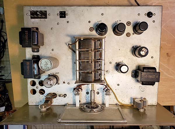
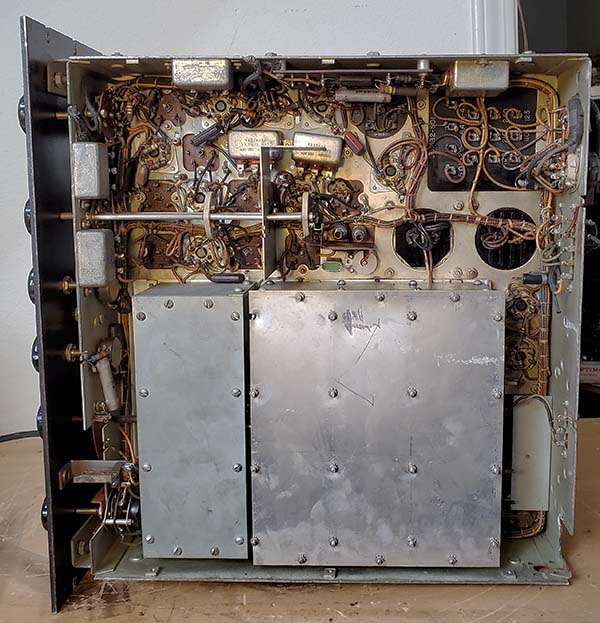
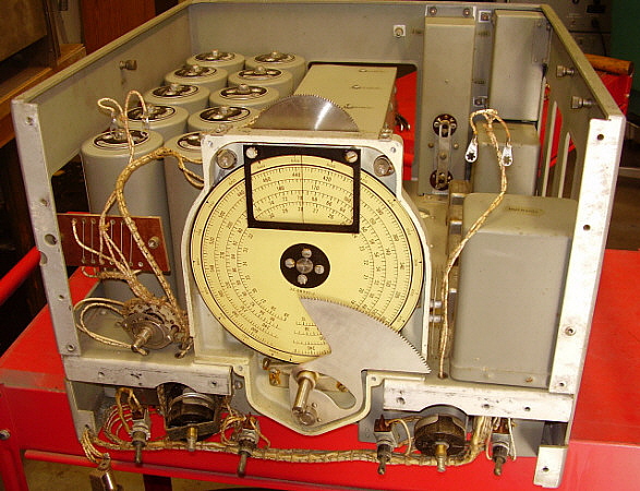
and dismounted. Now the front panel could be removed. Photo
right shows the RBA chassis with the panel removed. All
removed parts were "bagged and tagged" in small plastic bags.
This "bagging" method is extremely helpful to prevent loosing
any parts and for easing reassembly. Oct 16, 2017 |
 |
| Accessing
the Dial Mask and Band Switching - With the front
panel off, I could see the housing was a two-piece assembly. The
front part of the housing was mounted with four screws. The next
step is to remove the four screws and lock washers that mount
the front cover of the housing. Now the front cover can be
removed and this exposes the tuning dial and the band switch
arced gear. The dial mask is mounted to the front cover. In
addition to the dial mask there is also a gear on the back side
of the mask that engages the band switch arced gear and actuates
the band changing function. However, since the mask needed to be
restored it had to be separated from the front cover. This
required removal of the retaining collar that was mounted to the
band switch shaft. The set screw wasn't a hex like all the other
set screws had been. This set screw was a spline or
Bristol-type. Also, just to make removal difficult, the collar
was pinned to the shaft. This required driving out the securing
pin with a proper size punch. If done correctly with the proper
tool, the pin comes right out. The collar has to be placed on a
large vise that has the jaws slightly open. With a long thin
diameter punch, the pin can be driven out. The set screw was
only to keep the collar in place while the pin hole was drilled
and the pin driven in. It doesn't have much of a purpose now and
was easy to loosen. This allowed the collar to be removed and
the dial mask, band switch shaft and drive gear could be
separated from the front cover.
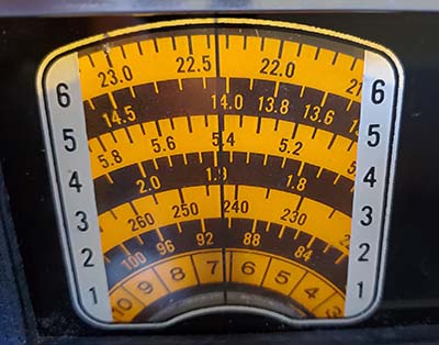
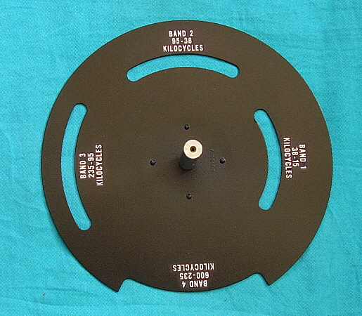
Painting the Dial Mask
- Once the dial mask was removed its condition seemed a little
worse than I thought. The minor flecks of corrosion were
numerous but most of them seemed to be around BAND 4. I removed
the black paint with stripper and wiped everything down with
denatured alcohol. I worked over the surface with steel wool to
be sure it was smooth and no blemishes would show when
repainted. I used Krylon Flat Black for the paint as the initial
coat.
photo right : The dial
mask/cover assembly removed exposes the dial and the arced band
switch gear. |
 |
| Restoring the Mask
Nomenclature - Of course, painting the dial mask
covered up the frequency band nomenclature. These letters and
numbers are embossed so they are somewhat higher than the flat
surface of the mask. To restore the nomenclature requires
carefully removing the paint just from the top surface of the
letters and numbers. I had to do the nomenclature recovery in
two steps. After the initial paint in flat black, I used a
special angled tool (that I made) that could hold a very small
piece of 320 grit Al-Ox paper. This was used to carefully remove
the paint just from the nomenclature. Of course, there was some
slight scuffing and other minor blemishes that happened to the
paint surrounding the nomenclature. The next step was to
carefully cut masking tape pieces to exactly cover only the
nomenclature. It sounds time-consuming but it only takes about
25 minutes to do. Next, I applied a coat of Satin Black, which
is much darker black than flat black. When this paint had dried,
I removed the masking tape. Now, only very small areas between
the letters and numbers had the flat black paint showing. These
areas were so small that I touched them up using a "ultra-fine
point" Pilot pen with black ink. The entire mask was then wiped
down with a clean cotton cloth to even out the paint surface. It
sounds like a lot of work and it is fairly time-consuming but
the results are worth the effort since the dial mask is quite
visible, directly in front of you, on all bands, whenever you're
using the receiver. Oct 19, 2017
Dial Mask and Band Switch
Reassembly - I put a small dab of grease on the mask
shaft and installed into the front cover of the housing. The
washer and collar were then installed onto the shaft and the
collar pin installed. The spline set screw was tightened. The
band switch was set on Band 2 so the mask was rotated to show
Band 2 also. The front cover was carefully placed in position
and moved slightly until the gears meshed while the mask
remained showing Band 2 centered. The four screws were
installed. The adjustment for the gear mesh clearance is
accomplished by moving the front cover upwards (reduces mesh)
and tightening the screws. Testing switching showed that the
mesh was correct as the switching was ultra-smooth and not
binding.
photo right: Dial mask
after restoration |
 |
| Front
Panel Restoration - This is really just a thorough
cleaning with a brass wire brush (suede shoe brush) and Glass
Plus to remove all dirt, grime and cigarette residue. The
original wrinkle finish is very tough and can take this type of
cleaning but you can't be real aggressive. You just want to
remove the dirt not the paint. The front panel had been stripped
of all tags and the two dial covers. The silver (engraved)
nomenclature needed substantial cleaning. The front panel must
have been pretty dirty as it took about five cleanings until the
paper towels didn't turn gray with dirt and stayed fairly white.
After this many cleanings, the nomenclature was very legible
now. Next is the touch-up. I've been using jet black
nitrocellulose lacquer for the last year or so. This method
replicates how the USN did "touch-ups" on equipment that was
being repaired but was not in the depot for an echelon-type
rebuild. The lacquer looks too dark when being applied but with
the final wipe down with 10W machine oil, the jet black matches
the original wrinkle paint color quite well. The touched-up
front panel is shown to the right.
DB Meter Repair
- The meter glass was broken in this meter. Luckily, it was a
Weston Type 506, which are very common meters. The mechanical
zero mechanism on a 506 is mounted in the glass making
replacement glass difficult, if not impossible. The easiest
method is to find a similar 506 meter that has the meter case
with mounting flange. It doesn't matter what the meter scale
is,...all I wanted was the metal case front with the glass. I
dug around in the junk boxes and found a good candidate. The
swap of the cases is easy only requiring removal of the three
mounting screws on each meter, aligning the meter zero
adjuster-pin with the adjustment slot while sliding the new
housing glass in place and then reinstalling the screws. The
only difference in the meter I used was that the glass was
standard while the original USN meter glass had a "non-glare"
treatment. Other than that, the transplant was perfect.
Oct 20, 2017 |
 |
| Plastic
Used in Logging Dial Window and Tuning Chart Cover -
These transparent plastic pieces are made of a celluloid-type of
plastic that is very sensitive to water. Just plain old H2O will
"fog" the plastic. The more water added, the worse the fogging
gets. With enough water, the surface of the plastic will begin
to dissolve. The only way to clean the plastic used in the
Logging Dial cover and the plastic used for the Tuning Chart
cover is to use oil. I used 10W machine oil (3 in 1 oil,
actually.) The oil cleaned the plastic surface and didn't cause
any change in the transparency. Another note on the Logging Dial
window, if this piece is dismounted only leave it dismounted for
enough time to clean it and the dial housing. This plastic piece
is fairly thick and if not secured by mounting screws it will
quickly begin to warp. I noticed the warp starting in about 15
minutes, so I remounted the plastic to allow it to retain its
proper shape. |
Front Panel Remount
- I had to touch-up all of the panel mounting screws with black
lacquer. Several were missing all of their paint but most just
had chips of missing paint. I mounted the two meters after I had
touched-up their mounting screws (and washers.) The most
difficult part of the front panel remounting is installing the
two chassis shims. These two pieces are mounted by the six
horizontal chassis screws. I had to have the six screws
protruding thru their respective panel holes to hold the two
shims in place while I guided the front panel into the proper
position to fully seat against the chassis and the side panels.
I also had to guide the four toggle switches along with the Gain
control and the Output Level control thru their respective panel
holes in order for the panel to fully seat. Once the panel is
seated all of the other panel screws were installed. All but two
of the panel to chassis mounting screws have nylock nuts that
complicate the panel installation, especially the six horizontal
chassis screws that have four of the nuts difficult to access
with a wrench. I first installed the other panel screws and nuts
but didn't fully tighten them. They were holding the panel in
place but allowed for minor movement. For the six horizontal
screws, the easiest method was to have the receiver upside down
as this allowed the best view of where the nuts had to go. Once
the nuts were installed I still didn't fully tighten the screws
yet. I still had to install the screws that mounted the chassis
withdrawal knobs. Once I had all of the panel mounting screws
and nuts installed and threaded together, then I could go ahead
and tightened all of the panel screws.
Each toggle switch had an flat washer, a hex nut and a dress
nut for their mounting. The switches and two controls use
external star locking washers that are mounted on the back side
of the panel and flat washers and hex nuts are used on the
front. The phone jack uses a special fiber insulator that has a
locating pin that has to be inserted into the mating hole in the
back of the panel. The phone jack body front just fits into the
recessed channel which keeps the phone jack from turning when
the panel nut is tightened. I had to make sure that two fiber
washers and one metal dress washer were used when installing the
phone jack nut. This was to provide the correct chassis
insulation and the proper spacing so the phone jack nut would
tighten up. |
| Reassembly
Notes - When I installed the metal spacer for the
band switch shaft I had to make sure that the spring washer was
mounted on the band switch shaft with the "fingers" facing up so
it pressed against the recessed area behind the spacer. This
spring provides a thrust load on the band switch shaft. When
installing the logging dial, it also had a spring that mounted
on the tuning shaft and loaded the logging dial. To synchronize
the logging dial, I first had to set the main tuning to the
minimum frequency on any band. I noted that the logging scale
actually is a little longer than the tuning scales but I had to
set the main dial to "0" on its logging scale. I then installed
the logging dial on the tuning shaft with the load spring in
place. I set the logging dial to read "0" on its scale and
pressed the logging dial firmly as far back onto the shaft to
load the spring and then tightened the set screws. I installed
the logging dial cover and checked the operation for any rubbing
or binding while tuning. I also checked that each 100s segments
on the main dial's logging scale matched the logging dial at "0"
or within a couple of divisions of "0." I then installed the
meter covers and then cleaned and installed the knobs.
I was pretty sure that during reassembly, with tightening up
the panel screws and the other mounting screws, some paint chips
were going to "pop off." I ended up with two fairly large chips
and several smaller chips. These were touched up with black
lacquer.
With everything back in place, retesting and troubleshooting
the Band 2 and Band 3 problems could begin. Oct 22, 2017 |
Minor Troubleshooting
- Problem one was with the DC Voltmeter reading very low.
Pressing on the meter face gently would result in the voltage
reading going up to normal, +220vdc. The problem was that I just
reinstalled the lug connections and didn't clean them first.
Cleaning with a brass wire brush got the terminals and lugs
clean and when reassembled, the voltage reading was normal.
Problem two was that the ANT. COMP. control wasn't indicating
the air variable position correctly. The ANT. INPUT shield has
to be removed (easy to do - only four screws) to see the plates
of the condenser. I set the condenser per the manual,...full
mesh is 10 to the right side of the scale. There's a rotation
limiting pin on the extension shaft thru the front panel that
only allows 180 deg. of rotation so the air variable position
has to match the panel scale.
On to the serious problems,... |
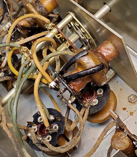
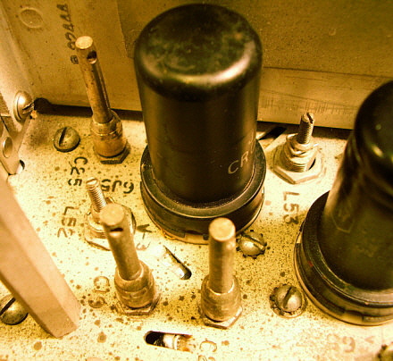
| Repairing
Split Hex-Collars on Air Variable Trimmer Capacitors
- So far, the problems had been minor stuff. I was now going to
find out why Band 2 and Band 3 were inoperative. I could hear a
few signals on Band 3 but they were very weak. Band 2 was dead.
I used a RF Signal Generator to inject a RMS voltage into the
Antenna Input to act as a steady, high-level signal. When
adjusting the trimmers to resonate the RF coils, the problem
became "painfully" obvious,...on Band 2, two of the air variable
trimmers had split hex-collars and the trimmer rotor had dropped
down and was "shorting" the rotor to stator plates which shorts
the RF coil which in turn takes the grid of that RF amplifier
tube to ground. I adjusted the rotors until they were fully
un-meshed which removes the short circuit but leaves that RF
coil "not tuned" and the rotor too low to mesh with the stator.
Enough signal leaks thru to tell that these are the defective
components keeping Band 2 from operating. I found that Band 3
had one split hex-collar trimmer that was already un-meshed.
This was why Band 3 seemed to work but had weak signals. Only
Band 1 and Band 4 had all good trimmers.
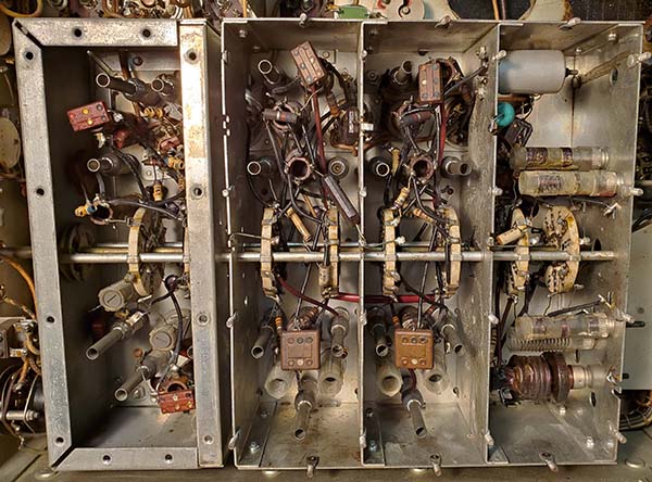
The repair of these split hex-collar trimmers requires the
removal of the defective RF coil assemblies. First remove the
shield-can by removing the top nylock nut and the four screws at
the base of the shield. Removal of the actual RF coil assembly
can be fairly difficult due to the 16 gauge buss wire used for
connections. This requires a fairly large soldering iron (or
gun, I used a Weller 250W gun.) On most of the buss connections
the wire is wrapped a half turn around the terminal. On some
wires, the joint can be heated and the buss wire lifted off of
the terminal with large needle nose pliers. Other joints may
require the use of a small pointed tool (like a small awl) to
get the buss wire bend started once the solder was molten. At
this point, long needle nose pliers can slightly unwrap the buss
wire from the terminal and then it can be lifted off of the
terminal. There are four buss wires and two stranded wires per
coil assembly that need to be removed. Once desoldered, then the
nylock nuts can be taken off and the coil assembly removed. Be
careful when doing the reinstallation of the buss wire onto the
terminals. If the buss wire was unwrapped too much it may break
when bending it back into position. Try to only unbend the buss
wire slightly when removing and then no problems should be
encountered when reinstalling. |
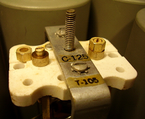
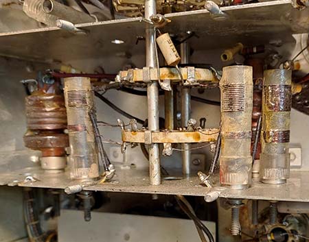
photo above: The hex-collar on the right is correct and not
split. The hex-collar on the left is split and has been taken
off to show the trimmer rotor shaft.
|
|
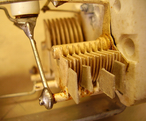
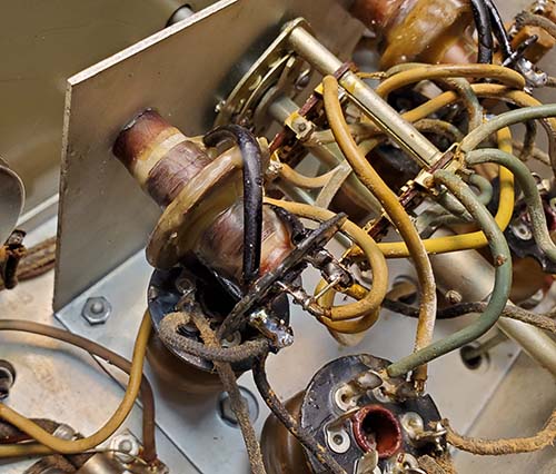
photo above: Cardboard shims are
installed between the rotor and stator plates to maintain proper
spacing for repair |
An ideal hex-collar repair would require access to a machine
shop to make a new hex-collar from 1/4" brass hex stock. The
shaft on the trimmer condenser is slightly tapered from 0.152"
up to 0.154" and this requires that the hex stock have a slight
taper also. The height of the collar is also important since the
press fitting of the collar will stop when the adjusting slot of
the rotor is at the top of the collar. This fit then has to
result in the proper spacing of the rotor and stator plates.
Original dimension for the height of the hex-collar was ~0.190"
and the new collar would also have this same dimension. The
final measuring involves having the hole perpendicular to the
top and bottom surfaces of the hex-collar to allow even movement
of the adjustment without binding. It's also possible to
correctly position the split hex collar on the shaft and then
drill and pin the collar to the shaft. The split should be
perpendicular to drill hole for highest strength. A very small
diameter steel pin will be necessary since the shaft is only
about 0.154" in diameter. The pin should be an easy "press fit"
since it's only holding the collar in position on the shaft.
Either of these two repair methods are
impractical for most restorers because we don't have access to a
machine shop. The next repair method described doesn't require
any special tools.
An easier repair of the split hex-collar is
to use solder to hold the hex-collar in place with the proper
spacing for the trimmer plates. Cardboard shim stock installed
between the rotor and stator bottom plates will provide a firm
stationary spacing for the plates. A minimum of four shims
should be used for best support of the rotor plates. I used
.022" thick cardboard that can be salvaged from small boxes or
the cardboard backing from tablets or from many other sources.
As long as the shim thickness is about .022" the plate spacing
will be correct.
The first step is to remove the RF coil assembly from the
receiver. I've tried to do this repair with the coil assembly in
place (just the shield-can removed) and it is almost impossible
to get the cardboard shims installed. There's just not enough
space for access and there's limited visibility, making the
whole operation impossible. Although it's difficult to unsolder
the 16 gauge buss wiring to remove the RF coil assembly, it's
easier than trying to do this procedure with the coil assembly
still mounted in the receiver. |
| Once the RF coil is removed, installing the
shims is easy. I use a pair of channel locks to gently lift the
rotor (with the hex collar installed so it will only move just
high enough.) I then slide in four shims. Now, release the
channel locks and remove the hex-collar. The slotted end shaft
will be at the correct height (for the hex-collar to be
sweat-soldered in place.) The slotted end of the shaft has to be
cleaned with a small jeweler's file but don't clean all the way
down to the stationary spacer. Just the upper half of the shaft
should be cleaned. Add some slight grooves with the file for the
solder to adhere to better. The inside of the split hex-collar
must also be cleaned with the small file. I used a large
soldering iron to "tin" the slotted shaft (250W Weller.) If the
hex-collar now won't fit on the shaft then file off some of the
solder until the hex-collar does fit entirely onto the shaft
with the bottom of the hex-collar flush with the stationary
spacer. Heat the hex-collar and shaft with the soldering iron
until it's hot enough that a very small amount of solder can be
melted. This solder will be wicked between the hex-collar and
the shaft and should provide a very strong bond. Add a little
more solder to the top slot area and create a slight solder
"dome" on the top. Let the solder cool and remove the shims.
I used a Dremel tool with a small cut-off wheel to make a slot
in the solder. This slot has to be widened by gently using a
hacksaw blade (blade alone - not the entire hacksaw.) Test the
trimmer rotation using a blade screw driver. It should now
adjust correctly. Check all of the wires and components on the
RF coil assembly to make sure there's been no damage during the
repair. If it looks okay, then reinstall the RF coil assembly
into the receiver. Oct 27, 2017
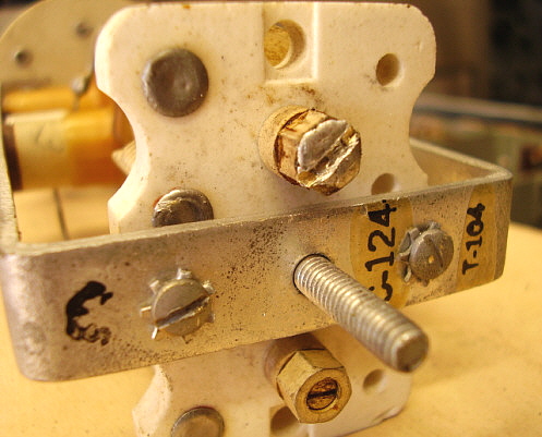
photo right: Finished
hex-collar repair showing the slot cut to allow adjustment of
the trimmer when RF coil is fully assembled. |
 |
| Another
Problem with Band 3 - Band 2 was performing very well
after repairing the two defective trimmers. However, Band 3
still seemed to be lacking sensitivity. Injecting a modulated
signal into the Antenna Input revealed that the RF trimmers were
all working correctly on Band 3. Switching off the modulation
and switching to CW (BFO on) should have resulted in a
heterodyne signal but no change was noted in the signal. I
adjusted the frequency to the top end of Band 3 (sig gen and
receiver) and adjusted the BFO trimmer and what happened wasn't
unexpected. Of course, the trimmer rotor dropped as soon as it
was unmeshed. The non-operational BFO had seemingly reduced the
sensitivity because no signals could be demodulated. To repair
the BFO on Band 3 is very similar to repairing the split
hex-collars on the RF coils since it's exactly the same type of
trimmer. >>> |
>>> The BFO coil assembly for Band 3 and Band 4 was
removed from the receiver. The trimmer was repaired per the
procedure shown above. After the BFO assembly was reinstalled,
the BFO didn't work on either Band 3 or Band 4. This could only
have been caused by the common return for both trimmer
capacitors. I ended up removing the BFO coil assembly again,
just to check it over closely. I found a questionable solder
joint on the common buss wire return that looked like it might
have been cracked but that should have only affected Band 3.
Before I reinstalled the coil assembly, I carefully resoldered
all of the coil wire wraps to the terminals as a precaution. I
installed the coil assembly and soldered the four buss wire
connections and the stranded wire return connection. Upon
testing, both BFOs worked. The problem was probably due to the
coil wire wraps around the terminals as these looked like
questionable solder joints. The shield cover was installed and
then the BFOs adjusted for 1kc above the tuned frequency on Band
3 and Band 4. Oct 29, 2017 |
| Trimmer Capacitors
Split Hex-collars - Notes - This splitting of the
hex-collar on this style of trimmer condenser is fairly common.
This type of trimmer was very popular in the mid-thirties up
into the mid-fifties. They're found in Hammarlund Super-Pro
receivers (they are a Hammarlund part - "ACP" Trimmer,) all BC-348 receivers other than Q, N and J versions,
Navy RBB and RBC receivers, on and on. It's likely the problem
is due to poor storage conditions and metal fatigue due to age.
When the metal was new the hex-collar could expand and contract
with varying temperature cycles. However, years and years of
thermal cycling will cause the metal to become brittle and
eventually it will crack. Poor storage in garages or sheds only
results in thermal cycles that are even more extreme and rapidly
cause the metal to become brittle. There isn't much that can be
done today except to repair the trimmers as they are
encountered. |
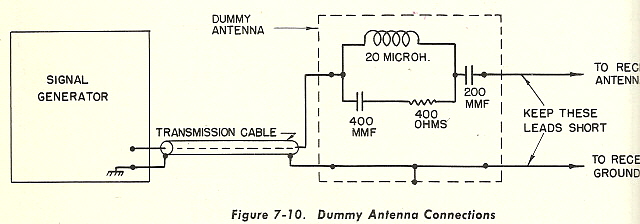
| Alignment
- The hex-collar trimmer repairs resulted in the RBA-1 now being
fully functional. The receiver requires a specific "dummy
antenna" to load the input regardless of the impedance of the
signal generator. Luckily, the schematic of the "dummy antenna"
is included in the NAVSHIPS manual. The parts required are one
20uH inductor, one 400 ohm carbon resistor, one 200pf capacitor
and one 400pf capacitor. The schematic is shown to the right.
The trimmers are all adjusted at the top end of each band. For
example, on Band 4, set signal generator to 600kc. Set receiver
to 600kc. With signal input to antenna input thru dummy antenna,
adjust all Band 4 trimmers for maximum deflection of the DB
meter. Reduce the GAIN control to compensate as the signal level
increases. Use lowest signal input that gives an indication on
the DB meter set at the lowest scaling. This is repeated for
each band.
The BFO is aligned at the top end and the bottom end of each
band. With 600kc unmodulated input and receiver tuned to 600kc,
switch on BFO. A 1kc heterodyne should be heard. Adjust BFO 4
trimmer to 1kc heterodyne, if necessary. Tune to 235kc and set
generator to 235kc. A 1kc heterodyne should be heard. >>> |
| >>> There are adjustments for the BFO inductance
for each band that are "thru the front panel." Two holes
are under the tuning chart (Left = BFO 3 and Right = BFO
1) and the two other holes have acorn head screw plugs
that are removed to access the holes (Left = BFO 4 and
Right = BFO 2.) Adjust BFO 4 inductance for a 1kc
heterodyne, if necessary. Check both the upper and the
lower frequencies to verify that the BFO is actually 1kc
higher than the tuned frequency. Tune the receiver up
about 1kc higher in frequency and the BFO should be zero
beat if it is set 1kc higher than the tuned frequency.
Repeat the adjustments until BFO tracks. Repeat the
procedure for each band. |
|
 |
|
| Is the Dummy Antenna
Really Necessary? - When the RBA-1 was in service and
being aligned at a USN depot, it was unknown to the radio repair
technicians what type of antenna was going to be connected to
the receiver. Shipboard antennae were quite different from USN
land station antennae. What the Dummy Antenna does is provide a
somewhat constant impedance load to the receiver that behaves
more like a typical antenna would than a direct connection to
the Signal Generator output would. The variability of what type
of signal generator was used probably also entered into the
alignment problems. Using the Dummy Antenna generally ensured
that every RBA would come thru alignment with the same
performance specification regardless of where it was going and
what type of antenna it was going to be used with. Today, most
of us are going to use one specific antenna with the receiver.
If it's an end-fed wire of considerable length, it might be
better to align the receiver with this antenna connected. Couple
a signal generator output to the receiver's antenna input by
using a small "antenna" on the signal generator output
consisting of a three foot wire that's near the receiver. This
will provide a frequency specific signal that can be adjusted
for amplitude, frequency and modulation (if needed.) This
simulates the receiver actually "picking up" a transmitted
signal and aligning the receiver for the best operation with the
antenna the is going to be used. In this type of set-up, the
load of the antenna is just as it is when the receiver is in
operation. This then provides an alignment that is exactly for
the actual antenna that is going to be used. Tuned loops are a
bit more difficult and experimentation would probably be best
with these types of antennae. Usually, the loop can be tuned for
the highest frequency on the band and then the receiver aligned
to that impedance load. Since there is no alignment adjustment
for the low end of the band, check to see if when the loop and
the receiver are tuned to the low end of the band that the
performance is the same as the upper end. When experimenting
with various antennae and alignment, only the antenna coils will
be affected and only those coils will require adjusting. |
| Cabinet
Restoration - I really didn't want to do an entire
respray of the cabinet. If I did, it wouldn't match the receiver
front panel. There was a lot of paint missing, especially on the
top. The first step was to remove the two data plates and then
to clean the cabinet's remaining paint with a brass wire brush
and Glass Plus. I then used black nitrocellulose lacquer to
repaint all of the areas that were bare metal. I let this set
for a day. The next step was to mix a very thin batch of lacquer
and thinner - about 2:1 ratio. With gloves on, I then used a
cotton pad saturated in thinned lacquer to "go-over" the entire
cabinet. This hides the "touch-ups" and ends up with the cabinet
looking in good original (although "touched-up") condition. I
then reinstalled the data plates and installed the receiver into
the cabinet. |
Antenna Connection to
Navy Coax Fitting - These Navy coax fittings are not
common making them difficult to find. There are two easy ways to
connect an antenna feed line to the RBA (or the RBB or RBC) that
allow use of coaxial cable and provide a good connection to the
receiver. Use a double female SO-239 adaptor. The outer diameter
will just fit into the Navy coax barrel. It will slightly
"thread" itself and make good electrical contact. However the
pin at the bottom of the Navy fitting is too far away to make
positive contact with the center conductor of the SO-239
adapter. I usually roll .010" thick brass or copper sheet metal
into a tube. The tube can then be inserted into the SO-239
adapter center barrel. The other end of the tube should be about
a .375" extension and the open end of it will fit over the Navy
center conductor pin. Another way to connect coax is to use a
female banana pin plug (these do fit onto the Navy center
conductor pin.) The coax center conductor can be soldered to the
female banana plug. The shield can have a drain wire soldered to
it and it can be connected to the ground lug on the back of the
RBA cabinet. |
|
Performance - Since I had the RBA-1 set up out in the
shop, I had to use the 270 foot long, center fed dipole. Since
the antenna is fed with open transmission line, I just
disconnected the two wires from the antenna coupler and, using
clip leads, shorted them together and then used a single 14
gauge stranded wire to connect the feed line to the receiver.
Perhaps this acts like a large "T" antenna that has the 77 feet
of feed line acting somewhat as a vertical with a large 270 foot
long "top hat." The "T" configuration was a popular antenna
during the early days of radio. During some of my initial
testing and troubleshooting I tuned in BO 359kc, the NDB from
Boise, Idaho - and this was during the day! Quite a
surprise,...but when I aligned Band 3 to the antenna, I tuned in
HDN 211kc in Gooding , ID, HLE 220kc in Hailey, ID and TCY 204kc
in Tracy, CA - during mid-day! Additionally, the normal daytime
copy of FCH 344kc in Fresno, CA, MOG 404kc in Montague, CA and
CC 335kc in Concord, CA were all present. None of these were
newly copied NDBs but I've never heard BO, HLE, HDN or TCY
during the day. The next day, I tuned in DC 326kc in Princeton,
BC, Canada. Incredible! This was at 13:30 in the afternoon and I
was hearing British Columbia. Another note, these stations were
being copied on loudspeaker, not 'phones. More experimenting
with other LW receivers will be necessary to determine if this
is RBA-1 performance (unlikely) or if it's antenna
performance (likely.)
Other daytime copies included the USN MSK stations NLK 24.8kc
in Jim Creek, WA, NAA 24.0kc in Cutler, ME, NPM 21.4kc in
Lualualei, HI and, although substantially weaker, HOLT 19.8kc in
Exmouth, Australia. These are very strong stations that are easy
copy, day or night.
The INPUT CLPG and ANT COMP. controls are very important and
must be adjusted for each band. In fact, the ANT COMP. should be
peaked every 10kc or so.
The OUTPUT control and OL switch are used as an audio AVC.
Once set, the audio output won't increase beyond the level set.
When there's a lot of static crashes or "popping" noises, the
OUTPUT (limiter) control helps keep your ear drums intact when
using 'phones. Nov 1, 2017 |
 |
| The following is a log of the stations tuned with the RBA-1
using the 270' CF with 77' of ladder line with wires shorted
together. There are six listening sessions within about a seven
week period that include both daytime and nighttime listening
periods. With the six sessions, I tuned in 100 different NDBs of
which six were newly heard stations. Greatest DX was DDP 391kc
in Puerto Rico which isn't unexpected since it runs 2KW. Other
DX (for a western US location) was FIS 332kc in Key West, FL,
YMW 366kc in Maniwaki, Quebec and DB 341kc in Burwash Landing,
Yukon. Daytime copy of British Columbia stations YZA 236kc and
DC 326kc was unexpected but was certainly due to the time of
year. Best LW reception is usually in November and December. The
large antenna was probably also a factor. Maybe the RBA-1 was a
factor, too. |
|
RBA-1, CFT-46154,
SN: 972 NDB Log
Antenna is 270' CF with 77' ladder line
with feedline wires tied together. Height is 30 feet.
Stations are listed in "as heard" order. Pacific Time. Newly
Heard NDBs - Maroon with asterisk. Unless otherwise indicated, all
reception is using 600Z ohm 'phones as audio reproducers.
|
Nov. 3, 2017 05:55-06:35 - Cndx Xlnt,
Quiet |
Nov. 9, 2017 19:10-19:40 - Cndx Poor,
Noisy |
Nov. 18, 2017 13:30 - Cndx Xlnt |
Dec 23, 2017 19:05-19:50 Cndx Xlnt |
1. UAB -200kc - Anahim Lake, BC, CAN
2. IP - 201kc - Mobile, AZ
3. YBL - 203kc - Campbell River, BC, CAN
4. TCY - 204kc - Tracy, CA
5. HDG - 211kc - Gooding, ID
6. LU - 213kc - Abbottsford, BC, CAN
7. QU - 221kc - Grand Prairie, AB,
CAN *
8. HLE - 221kc - Hailey, ID
9. YKA - 223kc - Kamloops, BC, CAN
10. LWG - 225kc - Corvallis, OR *
11. CG - 227kc - Castlegar, BC, CAN
12. VG - 230kc - Vermillion, MB,
CAN *
13. OKS - 233kc - Oshkosh, NE
14. BR - 233kc - Brandon, MB, CAN
15. OJ - 240kc - High Level, AB, CAN
16. AVQ - 245kc - Tucson, AZ
17. YCD - 251kc - Vancouver Is., BC, CAN
18. LW - 257kc - Kelowna, BC, CAN
19. HCY - 257kc - Cowley, WY
20. SLE - 266kc - Salem, OR
21. YK - 269kc - Castlegar, BC, CAN
22. XS - 272kc - Prince George, BC, CAN
23. GYZ - 280kc - Guernsey, WY - USCG
24. CEP - 278kc - Ruidoso, NM
25 QD - 284kc - The Pas, MB, CAN
26. EKS - 286kc - Ennis, MT
27. YYF - 290kc - Penticton, BC, CAN
28. TOR - 293kc - Torrington, WY
*
29. TV - 299kc - Turner Valley, AB, CAN
30. ONO - 305kc - Ontario, OR
31. UNT - 312kc - Penticton, BC,
CAN *
32. DC - 326kc - Princeton, BC, CAN
33. POA - 332kc - Hilo, HI
34. RYN - 338kc - Tucson, AZ
35. ZU - 338kc - Whitecourt, BC, CAN
36. DB - 341kc - Burwash Landing, YK, CAN
37. BKU - 344kc - Baker, MT
38. FCH - 344kc - Fresno, CA
39. SBX - 347kc - Shelby, MT
40. NY - 350kc - Enderby, BC, CAN
41. AL - 353kc - Walla Walla, WA
42. MEF - 356kc - Medford, OR
43. BO - 359kc - Boise, ID
44. YQZ - 359kc - Quesnel, BC, CAN
45. RPX - 362kc - Roundup, MT
46. 6T - 362kc - Foremost, AB, CAN
47. DPY - 365kc - Deer Park, WAWH2XVN copied on 183kc
at 05:57 |
1. ZQ -
410kc - Sir Wilfred Laurier CCGS, BC, CAN
2. MW - 408kc - Moses Lake, WA
3. MOG - 404kc - Montegue, CA
4. QQ - 400kc - Comox, Vancouver Is, BC, CAN
5. SB - 397kc - San Bernardino, CA
6. ULS - 395kc - Ulysses, KS
7. DDP - 391kc - San Juan, Puerto Rico
8. YWB - 389kc - West Bank, BC, CAN
9. JW - 388kc - Pigeon Lake, AB, CAN
10. WL - 385kc - Williams Lake, BC, CAN
11. PI - 383kc - Tyhee, ID
12. GC - 380kc - Gillette, WY
13. OT - 378kc - Bend, OR
14. EHA - 377kc - Elkhart, KS
15. EX - 374kc - Kelowna, BC, CAN
16. LV - 374kc - Livermore, CA
17. MF - 373kc - Rogue Valley, OR
18. HQG - 365kc - Hugoton, KS
19. DPY - 365kc - Deer Park, WA (2nd copy)
20. RPX - 362kc - Roundup, MT (2nd copy)
21. BBD - 380kc - Brady, TX
22. AP - 378kc - Active Pass, BC, CAN
23. MR - 385kc - Monterey, CA
24. HAU - 386kc - Helena, MT
25. CSB - 389kc - Cambridge, NE
26. PNA - 392kc - Pinedale, WY
27. DQ - 394kc - Dawson Creek, BC, CAN
28. FN - 400kc - Ft. Collins, CO29. MM - 411kc -
not on Navaid (MW w/o the dit?)
30. INUU - 395kc - I've copied this beacon many
times but have never found it on any Navaid. Oil Rig?
NOTE: Conditions were particularly noisy due
to a passing storm front and wind causing severe antenna
static. One of the problems with using an outdoor
antenna. Even indoor loops will respond to weather
fronts however.
|
Nov. 17, 2017, 19:00 - Cndx
Poor |
1. FS - 245kc - Sioux Falls, SD
2. YZA - 236kc - Ashcroft, BC,CAN
3. XC - 242kc - Cranbrook, BC , CAN
High level of static from passing front. Static was
so bad that OL didn't help. These are new copies for
RBA-1 only. |
As an illustration of how fast signal
cndx can change, I was running the RBA-1 in the early
afternoon on the loudspeaker. Copied for long time
periods the following stations,... 1. HLE -221kc -
Hailey, ID
2. HDG - 211kc - Gooding, ID
3. YZA - 236kc - Ashcroft, BC, CAN
The static level was very low and these stations were
easy copy on loudspeaker. This was at 1:30PM in the
early afternoon!
|
Nov. 22, 2017 21:10-21:40 -
Cndx OK |
1. LU - 213kc - Abbotsford, BC, CAN
2. RL - 218kc - Red Lake, ON, CAN - #
3. QU - 221kc - Grand Prairie, AB, CAN
4. YKA - 223kc - Kamloops, BC, CAN
5. DN - 225kc - Dauphin, MB, CAN - #
6. CG - 227kc - Castlegar, BC, CAN
7. VG - 230kc - Vermillion, MB, CAN
8. YZA - 236kc - Ashcroft, BC, CAN
9. AVQ - 245kc - Tucson, AZ
10. YCD - 251kc - Van. Is, BC, CAN
11. HCY - 257kc - Cowley, WY
12. LW - 257kc - Kelowna, BC, CAN
13. YK - 269kc - Castlegar, BC, CAN
14. GUY - 275kc - Guymon, OK - #
15. CEP - 278kc - Ruidoso, NM
16. YYF - 290kc - Penticton, BC, CAN
17. TOR - 293kc - Torrington, WY
18. ONO - 305kc - Ontario, OR
19. VC - 317kc - LaRonge, SK, CAN - #
20. MA - 326kc - Midland,TX - #
21. DC - 326kc - Princeton, BC, CAN
Static level was moderate even though weather and
wind were calm. Most are repeat copy but five new
stations to this receiver (marked with #.)
Total NDBs copied with this RBA-1 = 100
Total newly heard NDBs = 6
|
|
1. GDV - 410kc - Glendive, MT #
2. MW - 408kc- Moses Lake, WA
3. QQ - 400kc - Comox, BC, CAN
4. ENS - 400kc - Encenada, BCN, MEX #
5. FN - 400kc - Ft. Collins, CO
6. DQ - 394kc - Dawson Creek, BC, CAN
7. YWB - 389kc - West Bank, BC, CAN
8. WL - 385kc - Williams Lake, BC, CAN
9. HAU - 386kc - Helena, MT
10. YPW - 382kc-Powell River, BC,CAN#
11. GC - 380kc - Gillette, WY
12. K2 - 378kc - Olds-Didsbury, AB, CAN#
13. EX - 374kc - Kelowna, BC, CAN
14. YK - 371kc - Yakima, WA#
15. YBV - 370kc - Berens River,MB,CAN#
16. SX - 367kc - Cranbrook, BC, CAN#
17. YMW - 366kc - Maniwaki, QC, CAN#
18. HQG - 365kc - Hugoton, KS
19. AA - 365kc - Fargo, ND#
20. BF - 362kc - Nolla-Seattle, WA #
21. PTT - 356kc - Pratt, KS#
22. IN - 353kc - International Falls, MN #
23. PG - 353kc - Portage, MB, CAN #
24. SBX - 347kc - Shelby, MT
25. MNC - 348kc - Shelton, WA #
26. FCH - 342kc - Fresno, CA
27. RYN - 338kc - Tucson, AZ
28.
LF - 336kc - LaSalle, MB, CAN *
29. FIS - 332kc - Key West, FL #
30. DC - 326kc - Princeton, BC, CAN
31. MA - 326kc - Midland, TX
32. YQF - 320kc - Red Deer, AB, CAN #
33. VC - 317kc - LaRonge, SK, CAN
34. YYF - 290kc - Penticton, BC, CAN
35. EKS - 286kc - Ennis, MT
36. CEP - 278kc - Ruidoso, NM
37. XS - 272kc - Prince George, BC, CAN
38. YK - 269kc - Castlegar, BC, CAN
39. ZSJ - 258kc - Sandy Lake, ON, CAN #
40. ZYC - 254kc - Calgary, AB, CAN #
41. YCD - 251kc - Vancouver Is.,BC, CAN
42. FS - 245kc - Sioux Falls, SD
43. YZA - 236kc - Ashcroft, BC, CAN
44. FOR - 236kc - Forsyth, MT
Xlnt cndx. One newly heard "LF 336kc" and 19 new
copies for this receiver marked with #. |
|
|