|
Diversity receiving equipment utilizes two or more
receivers connected together at the second detectors and AVC lines. The receiver
inputs are from widely separated antennas. The goal of a diversity receiver is
to greatly reduce
or eliminate fading radio signals. Fading radio signals have always plagued
shortwave reception and are encountered when the signals
being received originate from a transmitting station located at a distance that requires
the radio waves to propagate via skywave through the ionosphere. As signals fade down to the noise
level much of the information being transmitted is lost until the signal level increases
above the noise again. Sometimes deep fades will last for half a minute or more,
causing program interruption or important messages to be lost. Besides fading,
other phenomena occurs
when radio waves are refracted through the ionosphere, such as selective
sideband fading causing distortion on AM signals along with rotation of the
radio waves causing polarization changes.
|
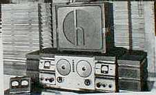
Cover "Proceedings of The
Radio Club of America, Inc." May 1993 |
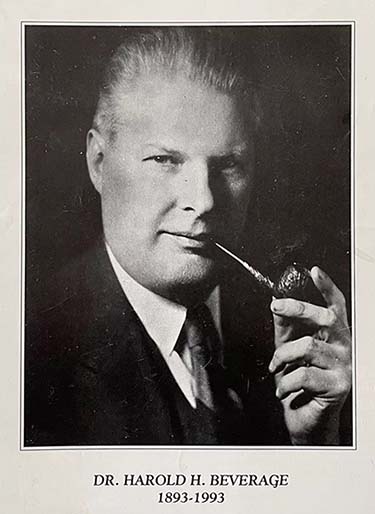
In the early 1920s, two engineers working for RCA,
Dr. Harold
H.
Beverage and H.O. Peterson, began investigating what was actually happening when
signals faded. The event that fomented Beverage and Peterson's
interest happened when the two were monitoring signal reception
from two points simultaneously. They were utilizing a telephone
line to monitor Peterson's receiver at his home and were
comparing that to the received signals from the RCA station
site, located about one-half mile away at Riverhead, Long
Island, New York. By monitoring the same
transmitter signal as received from two different locations
simultaneously, Beverage and Peterson noted that each station
received the signal with different fading characteristics. More
tests showed that different fading occurred with as little as
three hundred feet of separation of the receiving antennas.
Beverage and Peterson first connected strip-chart recorders to a
combination of three antennas and three receivers. The charts
showed that not only was the same signal at different amplitudes
at each antenna but, at any one instant, the signal at one
antenna was also many times out of phase with that same signal
on the other antennas. At first the engineers speculated that
radio waves were being refracted in the ionosphere at different
angles and therefore some waves would be intercepted by an
antenna while other wave-angles would miss the antenna. |
A large multiple antenna should capture more
wave angles and reduce fading. Actually, they found the opposite
happened. Fading became worse with larger antenna arrays. The two men
then theorized that over-the-horizon radio waves could be refracted
simultaneously from different heights in the ionosphere, these waves
would travel slightly longer or shorter paths and arrive at a single
antenna at slightly different times. The delay of the longer path
signals would sometimes cause multiple phases of the signal to occur on
a single antenna. Sometimes the phase differences would add resulting in
stronger signals and sometimes the phases would cancel causing a drop in
signal strength. Since the ionosphere was nearly always in a changing
state and since radio waves would frequently be simultaneously refracted
at several different levels in the ionosphere, fading due to radio wave
phase changes on a single antenna was always going to be present.
 |
The solution was to use
separate antennas and separate receivers to provide the
isolation necessary so each antenna and receiver would react to
radio waves specific to its time and space relationship. As the
signals passed through the receivers, the various phases at the RF frequency maintained their out of phase relationship until
they were converted to audio signals at the second detector. The
process of detection eliminated the RF out of phase nature of
the signals since now the signal information was at an audio
frequency. |
Each second detector output would be tied together
with a common load, operating an AVC system that interconnected
all the receivers, resulting in a single audio signal the
amplitude of which was the result of the strongest received
signal at any one time. Through experimentation, it was found
that at least a full wavelength of antenna separation was
necessary to have consistent difference in the phase of the
signals. >>>
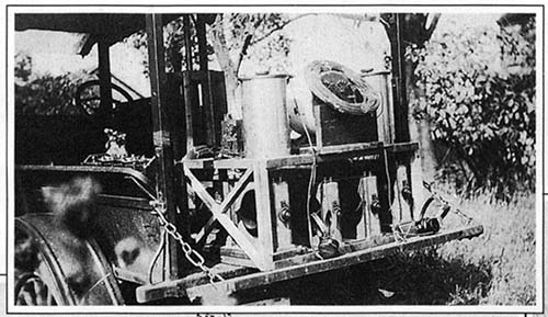 |
The truck loaded with receiving
gear was driven around Riverhead taking signal measurements to
determine just how fading radio waves reacted in different
locations.
photo: Radio Club of America |
|
>>> Additional
problems started to surface when it became necessary for the diversity
receivers to operate on CW. The interaction of the receivers in
maintaining a constant detector load output regardless of variations on
the separate antenna-receiver inputs required the AVC to be operational.
When a BFO was injected into the second detectors the strength of the
BFO oscillator would capture the AVC and not allow it to follow the
signal strength variations in that receiver.
 |
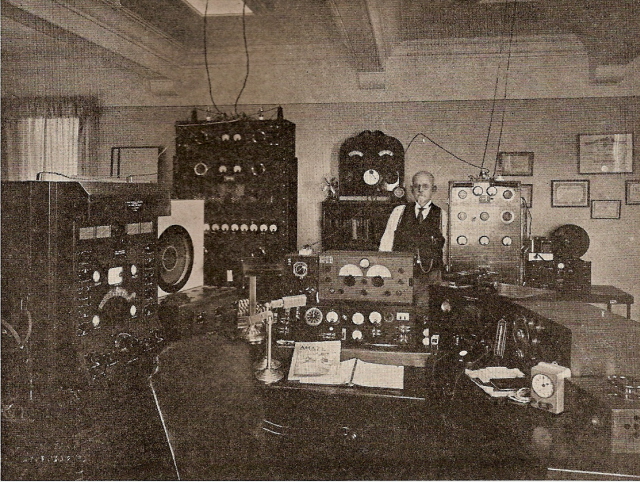
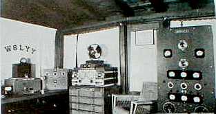
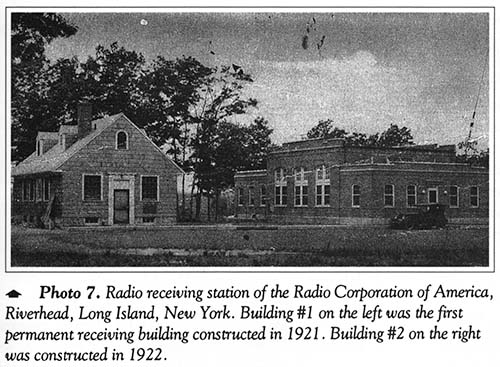
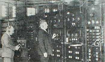
Inside the RCA LW Station at
Riverhead about 1921 showing the various receivers used for
long wave communications.
photo: Radio Club of America |
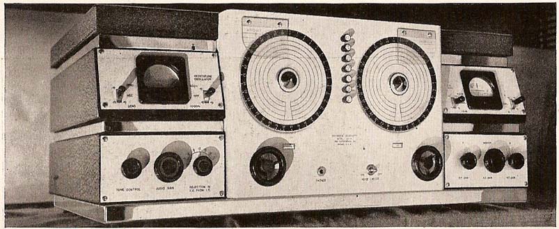
The solution was to either send
modulated CW from the transmitting station, which wasn't always practical, or the second
detector outputs could be used (without a BFO) to operate an external device called a Tone
Keyer. The Tone Keyer provided a clean CW output that was devoid of any noise, static or
interference since it was "keyed" from the diversity output of the detectors.
This then allowed the system AVC to be in operation and standard CW to be
received. Beverage and Peterson, while working at Riverhead, NY,
installed the first space diversity stations for reliable, long-distance
communication.
|
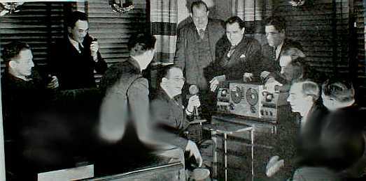
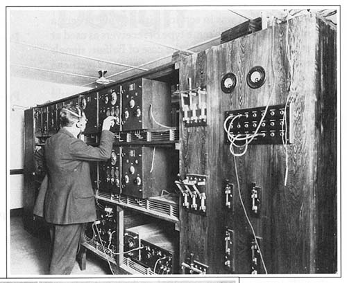
H.O. Peterson (left) and H.H. Beverage testing and adjusting
the triple diversity receivers at Riverhead, Long Island, New York.
Photo from August, 1933 - Radio News
|
By the late
twenties, RCA had 41 triple-diversity receivers installed at Riverhead in communications
with 26 different countries. The outputs were routed to a main office in New York City
where operators would copy the strip tapes, decoding the messages. By using filters and
multiple tones, several signals could be routed simultaneously to the main office without
interference. The associated antenna farm, with 1000 feet of separation between antennas,
required acres of land. The installation was used for commercial sending and receiving
world-wide radiograms. |
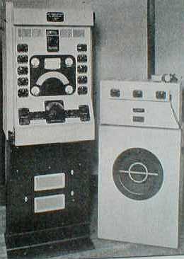
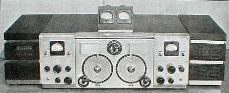
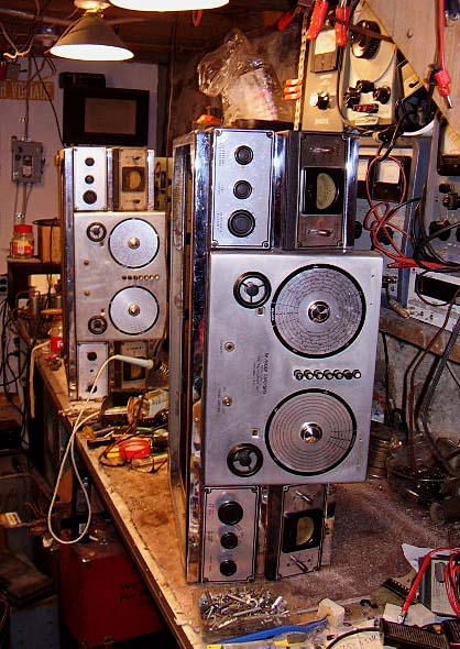
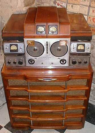
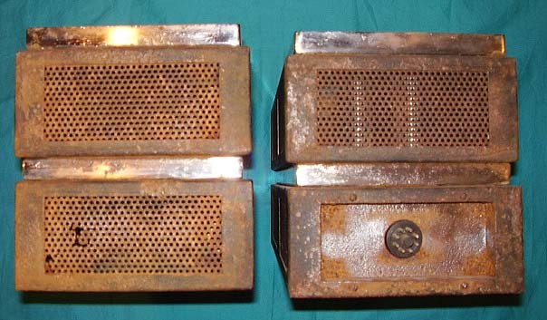
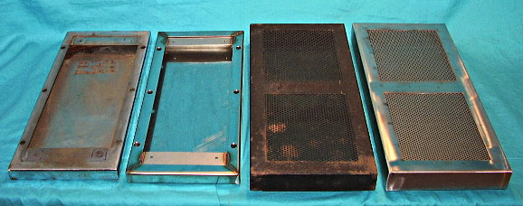
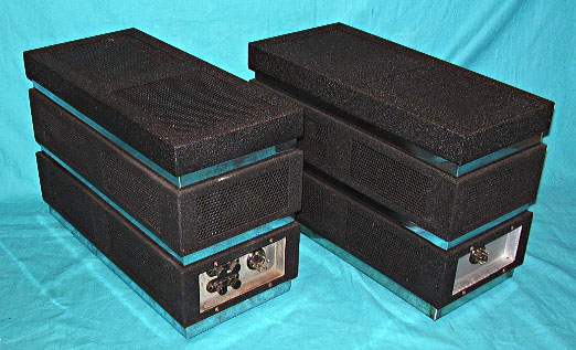
As receiver design progressed, the diversity stations became more
sophisticated. By the forties, RCA had introduced its AR-88 receiver which was adapted to
the new triple-diversity receiver, the DR-89 (Navy designation RDM.) These seven foot tall racks contained three
AR-88 receivers, a Tone Keyer with combined output meter, a Speaker Panel, a Meter Panel
with S-meters for all three receivers, an antenna patch panel and a power supply. Even more
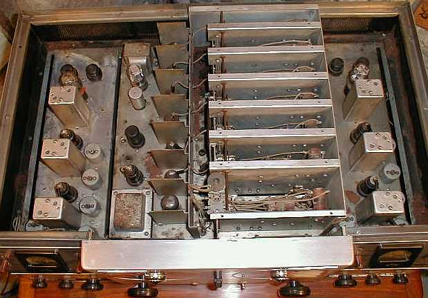
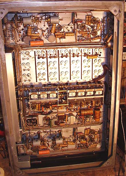
complex was the military RCP and RBP-1, also built by RCA for the Navy during
WWII. The RCP used double conversion receivers with multiple tuners installed in four, seven foot
tall racks. The RBP-1 was a dual-triple diversity receiver that was essentially two
RCPs
side-by-side. Using six double conversion receivers in seven racks the entire setup
weighed a mere one and a half tons! The RBP-1s were still in use as late as the 1970s.
The Signal Corps also used
diversity in many of their teletype installations. The system used was
"frequency diversity" which used one frequency and receiver for "mark" and
another frequency and receiver for "space." The theory was that each frequency
would fade differently and rarely would both frequencies fade together. Only
either a mark or a space was needed to decode the teletype, (if it isn't a mark
- it must be a space.) The popular receivers used were the Collins R-388, R-390
and the R-390A.
Another form of diversity
was to use a vertical oriented antenna in combination with a horizontal
antenna. The theory was that the radio waves many times rotated as they were
refracted through the ionosphere and therefore good diversity action could
be achieved with both vertical and horizontal polarization. This form was
called "polar diversity" and was generally used when a full wavelength of
antenna separation wasn't practical. In the early forties, a QST article featured a novel way to
experience a diversity action using only a single receiver. The writer used a high speed
antenna switch, running at 400Hz, to switch between two antennas. The average of the
signal strength of each antenna was more or less what the receiver responded to supposedly
giving some relief to fading. Additionally, the 400Hz switching gave a sort of modulation
to the signals so CW was easy to copy without a BFO.
Amateur interest in diversity reception waned as WWII loomed in
the near future. The expense, the complexity, the space required for antennas all made the
results not worth the effort. With less expensive equipment most hams could get the same
results. So what if the 'phone stations needed to repeat some of their transmission. On
CW, there was no obvious benefit to diversity and, in the pre-WWII days, most hams were on
CW. After WWII, there is hardly any mention of diversity in any ham magazines.
The commercial stations and the military had always been and were to remain the
primary users of diversity reception. As technology progressed into satellite
communications by the late 70s and other more reliable forms of communication
came into use, the need for large, expensive diversity receiving installations
all but vanished. Most of the equipment has been scraped or sold into surplus.
|