Radio Boulevard
Western Historic Radio Museum


A. H. GREBE & COMPANY, INC.
 

A GUIDE TO THE SYNCHROPHASE MU-1

Brief History  -  The Circuit Design  -  The Evolution of the Synchrophase MU-1,  MU-2

Engineering Upgrades in Chronological Order 

The Serial Letter Dilemma  -  MU-1 & MU-2 Serial Letter Log

Cleaning & Restoration  -  Operation & Neutralization  -  Performance Testing Two MU-1s  

by: Henry Rogers - WHRM

above: Color artwork of the Grebe MU-1 from the 1925 advertising brochure

For decades, vintage radio collectors have rated the Grebe Synchrophase MU-1 as one of the best, if not "the best," Battery-operated TRF-Neutrodyne radio receiver from the mid-1920s, with performance that is matched with timeless styling. However, anyone that has taken a close look at more than a few Grebe Synchrophase MU-1 receivers has surely noted that there are some significant differences between the various MU-1 receivers produced. During the mid-1920s, RADIO was evolving so fast Grebe had to continually re-engineer the Synchrophase to keep it up to date. This article will attempt to catalog as many upgrades as possible with explanations as to their purpose. This article will also assign a chronological order to the upgrades so the Synchrophase owner might be able to date when his radio was built from certain easily observable construction details. Also, we will attempt to decipher Grebe's serial letter methods so that dating by this combination of letters may become possible in the future (this attempt has actually produced another interesting possibility for the serial letter codes.). A serial letter log has been started and this article will keep track of the information in that log. Finally, this article will show how I restore the MU-1 receivers, how to balance the neutralizing capacitors and what kind of performance you should expect from your Synchrophase. As with all of our articles, we try to provide the most detailed and accurate information available. If you have a Grebe MU-1 or MU-2 that differs from what is presented here, let me know. Here's an e-mail link.  E-mail:  WHRM GREBE SYNCHROPHASE MU-1, MU-2 INFO -  Henry Rogers Nov. 27, 2010


Brief History of the Synchrophase -  Alfred H.Grebe was born in 1895 and started in the "radio business" at a very young age. He was certainly selling various pieces of equipment he built to radio amateurs prior to WWI, he supplied a "submarine receiver" to the Navy during WWI and continued on building amateur radio receivers after WWI. 

Grebe produced a series of ham receivers designated with a "CR" prefix followed by a number to identify the model. The CR receivers were very popular with the hams and, if a commercially built receiver is seen in a vintage photograph of an old ham station, it will more than likely be a Grebe "CR" receiver. The amateur business was large enough that, by 1920, Grebe had a fairly large building for radio manufacturing. The A. H. Grebe  & Co., Inc. was incorporated in January, 1920.

When Westinghouse started their commercial broadcasting station, KDKA, in November, 1920, the general public became aware that "RADIO" could be more than the dots and dashes of International Morse. Prior to professional commercial broadcasting, 99% of what was on the air was in International Morse. The general public's opinion was "why buy a radio, I don't know Morse." Broadcasting was beginning to develop through 1921 and by mid-1922, there were over one hundred licensed "commercial" broadcasting stations on the air.

The Broadcast Boom created an insatiable market for radios,...any radios. Radio receivers that had previously been for radio amateurs were sold as broadcast receivers. Old radio companies like Kennedy, Adams-Morgan and others, that were primarily ham or experimenter builders, offered their radios as broadcast receivers.
Grebe marketed some of their CR receivers as broadcast receivers since they did tune around where the BC stations were transmitting. The 1922 CR-9 was the most popular early Grebe CR receiver since it included a two-stage audio amplifier section in addition to the regenerative detector. Additionally, Grebe later offered the CR-12 and the CR-14 specifically as Broadcast Receivers. The 1923 CR-12 shown to the left has "Broadcast Receiver" engraved on the front panel.

By 1924, there were hundreds and hundreds of companies building radios. Many of the radios produced were basic designs that functioned adequately but were not innovative since the companies were small owner-engineer operated concerns that didn't have the financial ability to become competitive. Grebe however was already a major manufacturer and, in early 1924, it was decided that a radio specifically designed for Broadcast reception was something the company should provide to the radio enthusiasts.

The Synchrophase was born out of Broadcast Boom but was really not marketed during that period which ended around the beginning of 1924. By mid-1924, radio buyers wanted great performance and easy operation. Grebe had some top engineers that designed a receiver that was made up of innovative components rather than a special circuit. Grebe components were built at the factory. They had their own bakelite molding facilities, their own screw machines, plating facilities, everything required to build first-class equipment. The new Synchrophase's mechanical superiority was due to the experienced manufacturing ability of the Grebe company.

Then there was the styling. The Synchrophase had to look like no other radio. Grebe went for mounting the tuning condensers facing upwards with "on edge" dials that were surrounded by dull 24K gold covered and lacquered diamond-shaped escutcheons (early models only.) When mounted on the faux grained dark red mahogany bakelite panel the effect was mildly Oriental in style but certainly striking and looked like no other radio on the market.

Finally, there was the performance. The new Synchrophase literally was the best performing non-superheterodyne radio available in 1924. It was one of a few TRF designs that could complete with the Westinghouse-GE-RCA superhet receivers. Amazingly sensitive and very selective, easy to operate and incredibly good looking - all for $155. The Synchophase was so popular, it was available from around August 1924 up to the summer of 1927. Probably over 150,000 Synchrophase MU-1 and MU-2 receivers were built during that period. An incredibly long production life considering the rapid evolution of radio designs during the 1920s.

The Synchrophase Circuit Design - The Synchrophase is a Neutrodyne, no doubt about it. Look at the schematic and you'll notice the feedback capacitors (Grebe called them "balancing condensers") from the plate to the grid on the two RF amplifiers. The only problem was the Neutrodyne circuit was owned by the Independent Radio Manufacturers who had paid Louis Hazeltine to design it exclusively for them. So, here was Grebe, not an IRM member (unless you were one of the eleven founding companies, you couldn't be a member) and he was building a Neutrodyne. The law suit was inevitable but Grebe production was never stopped. Eventually, Synchrophase production reached 150,000 radios before the court even heard the case in June,1927. By that time, the Synchrophase was already obsolete. Grebe lost the case but was able to obtain a Neutrodyne license anyway. But, so much for the legal story. Now, on to the circuit innovations.

As stated in an April 1925 QST article by Ralph Batcher, one of the Grebe designers, it wasn't so much the circuit as it was the unique, precision components that made the Synchrophase such a great performing receiver. First were the "Binocular Coils." These were wound with Litz wire and then the RF impedance was checked to make sure all the wires of the Litz cable were correctly soldered. DC resistance checking would not show complete connections. The dual coils were connected to cancel the field and prevent coupling. Also, the primary was wound with very fine gauge wire (~40ga.) that allowed more turns and the primary was mounted inside the secondary to allow the field to act as a shield. The binocular coils provided the intra-stage isolation needed for the Neutrodyne RF stages to function without adding stray coupling to the RF amplifiers. The Binocular Coils were designed by P. D. Lowell.

The tuning condensers were very small due to the high inductance value of the binocular coils. In 1924, the Grebe tuning condensers were the smallest value found in production radios. Additionally, the cut of the plates allowed for a Straight-Line-Frequency change per the inductance used in the tuned circuit. This was found experimentally in the Grebe labs and resulted in a sort of square looking plates on the condensers. The end result was even spacing of the stations across the tuning range. The S-L-F condensers were designed by Ralph Batcher.

Most battery sets of 1924 controlled their output level by increasing or decreasing the tube filament voltage. More sophisticated radios might split the function to have many filament controls so the circuit could be adjusted for every signal type. Grebe decided that the filaments could be set at some reasonable level and the actual volume of the audio controlled in another manner. The Synchrophase uses a variable resistive shunt across the primary of the second audio interstage transformer to act as a volume control.


photo above: The earliest version of the Synchrophase from late-1924   (MU-1 LYWA)

As "RADIO" evolved through the mid-1920s, so did the Synchrophase. The 1924 models are very different from the 1927 models. Although they appear almost identical on the exterior, inside the circuit kept up with the quick evolution of radio circuits during the twenties. Consequently, users today will find that the later Synchrophases are much better performers than the early versions. Later versions have a very wide tuning range, dial lamp, fuse, low frequency audio transformer, non-microphonic sockets and audio power galore. So, even though they appear the same on the outside, inside the variations of the Grebe Synchrophases offer a continual look at the evolution that was necessary to stay competitive in RADIO during the 1920s.


The Evolution of the Synchrophase MU-1 and MU-2


The Early Production Synchrophase MU-1 Receivers - Aug. 1924 to mid-1925

The first version of the MU-1 has individually operated tuning condensers. The dials are scaled 0 to 100 with gold-filled nomenclature. Each dial has a small vernier adjustment wheel directly below the dial at the bottom of the panel. The typical early MU-1 will tune up to just over 1300kc. Taking into account that most collectors know that the later MU-1 had "chain-coupled" dial drives, these early versions are sometimes referred to as "No Chains" or something similar. The "No Chains" versions were built for almost a year - probably from August 1924 up to mid-1925. The article published in April 1925 QST shows the early version of the MU-1 and makes no mention of any improvements planned so our assumption is that the early version was produced up to around the middle of 1925.


photo above: The VOLUME control is a stepped resistive shunt across the second AF interstage transformer primary.

The Volume Control is a variable resistance shunt across the primary of the second audio interstage transformer. Five wire-wound resistors are used in a six-position contact switch, stepped-control arrangement. The first schematics of the MU-1 show a continuously variable resistor rather than the stepped-control, however, it's unlikely that a continuously variable resistance (alone) was used since it would be possible to effectively short circuit the primary and allow the +90vdc battery to be connected to the 1AF plate without a load. The highest position contact is not connected to the shunt. This effectively allows the highest position of the Volume Control to disconnect the shunt from across the primary of the second audio interstage transformer. Additionally, there is a series resistance that limits the minimum shunt value to approximately 300 ohms.

The very earliest Synchrophase receivers had small round escutcheons for both the Filament and the Volume controls. These early escutcheons are marked only with "INCREASE" and an arrow. The Instruction Card under the lid let the users know that the right hand control was the FILAMENT adjust and the left hand control was VOLUME. In fact, the Instruction Card shows the escutcheons with just INCREASE on them.


photo above:
Grebe MU-1 CTPB shows the early version chassis layout. Note that both audio interstage transformers are identical in size and ratio. Normal DC resistance is 330 ohms for the primary and 6600 ohms for the secondary. Both bypass condensers are very long metal case units painted gloss black. Early to mid-production routes two buss wires over the B+ bypass condenser. The C- bypass condenser can just be seen mounted under the central tuning condenser. Note that early receivers do not have "Binocular Coil" labels mounted on the top covers of the coil assemblies.  

photo above: from MU-1 LYWA  

These are photographs of the early versions of the escutcheons for the FILAMENT and VOLUME controls. To the left is the first escutcheons used. Both are identical and only have INCREASE between an "arrow" indicator. The Instruction Card told the users which control did what.

The two photos to the right show the next escutcheons used. These are marked VOLUME with INCREASE and the arrow along with the numerals 1 through 6. The other escutcheon is marked FILAMENT with INCREASE and the arrow along with 0 for the OFF position and 1 through 5. These escutcheons are found on the Synchrophase receivers up until the engineering upgrades of 1925.  NOTE: It's been reported that MU-1 JRPI has FILAMENT-INCREASE for both escutcheons.

Also note in these photos of the escutcheons that the faux mahogany bakelite is mottled grain on the earlier panel to the left and is linear grain faux mahogany on the just slightly later panel to the right.                         

 photos above and right: from MU-1 CTPB


The front panel is made out of bakelite with the front side faux wood grained to look like mahogany. Sometimes the faux pattern appears "mottled" to simulate burl grain and sometimes the grain pattern appears linear. This seems to be variations in the manufacturing of the panels because there is no consistency with both linear and mottled panels appearing throughout production of the Synchrophase.
The early Hook-up Cards are cream colored stock with black lettering and drawings. Note that the underside Hook-up Card shows that the B batteries consist of four +22.5vdc batteries to provide the +45vdc and +90vdc required. Also shown is a horn speaker representation for the loud speaker hook up.

Early Instruction Cards are cream colored stock with black lettering. The representation of the receiver's front panel is very large with all of the controls plainly identified. There is a list of accessories required that names the tubes needed, batteries, loud speaker and antenna. There is also a tuning log that was filled out at the factory and shows the exact dial settings for specified wavelengths. Note that the round escutcheons on the card only have INCREASE on them. Additionally, the serial letters are written in an area in the upper right hand corner of the card.


The Intermediate Production Synchrophase MU-1 Receivers - mid-1925 to mid-1926

Single-Dial Tuning with Ball Chain Drive - With the increasing popularity of the Tuned Radio Frequency circuit, with its typical "three dial" tuning system, complaints regarding the difficulty of manipulating three different dials seemed to be the topic of extended discussions. Various mechanical coupling systems had been introduced as early as the Ther-mi-o-dyne radio's rack and pinion coupling system from 1924. The difficulty was in the precision necessary in the construction of the coils and of the tuning condensers. Each part had to be exactly built in order for mechanical tracking to be accomplished. The technology versus cost wasn't really available for the typical radio manufacturer at the time. Grebe came up with an easy mechanical coupling that, while allowing "single-dial tuning," also was very easy to change to an individual dial tuning for the user that wanted better accuracy. The use of the "ball-chain drive" was a solution that, while not very precise, did allow Grebe to advertise that the Synchrophase could now be tuned with a single dial (first advertised in August, 1925 but patent filed on May 13, 1925.)

The system works from the central dial which has two drive sprockets mounted on top of the dial. From the central dial out to each of the other tuning dials a ball-chain is mounted to sprockets that are mounted on top of those dials. The central dial thus drives the two outer dials via the chains. If individual dial tuning is desired, the knurled nut on top of the outer dial sprockets can be loosened and then that sprocket will not turn that dial. The user could also use the knurled nuts to disengage the outer dials, then precisely tune in a station and then tighten the knurled nuts and the receiver was then "calibrated." Additionally, there was always a bit of play in the chain coupling anyway, so minute adjustments could be made for precise tuning. Though the ball-chain drive does pre-date the next upgrade, not many (if any) Synchrophase receivers were built with the ball chain drive but without the Low Wave Extension Circuit.


photo above: Grebe MU-1 SRSS shows the chassis layout after the mid-1925 upgrade showing the addition of ball chain drive for single-dial tuning. The band switch is directly behind the left dial and the center dial. Note that the switch is activated by a lever that exits from under the rear of the center dial and engages the switch slide through a slot.


photo above: Chain drive and band switch on MU-1 SRSS - Note the lever that exits from under the center dial and engages the bandswitch. Also note, just one lid prop.

Band Switch aka Low Wave Extension Circuit - In mid-1925 the Synchrophase was subjected to a major upgrade that dramatically enhanced the performance of the receiver. As more and more broadcast stations were licensed and came on the air, the Department of Commerce (in charge of radio regulation at the time) had to begin moving radio broadcasting stations to different frequencies. Early regulations had stipulated that all broadcasting would be on 360 meters or 400 meters wavelength. By 1923 it was apparent that this was an unworkable plan and stations would have to "spread out" over a designated band. Due to the international emergency frequency of 500kc and the bottom of the 160 meter amateur band at 1750kc, a "Broadcast Band" would have to squeeze into this part of the spectrum. Eventually the Federal Radio Commission made the official Broadcast Band span 550kc up to 1500kc with 10kc separation between stations (but that was in 1927.)

By 1925, the Department of Commerce had already been moving stations up to the higher frequencies of the "unofficial BC band." As a result, the early Synchrophase receivers that only tuned up to ~1300kc were now not able to tune in these newly licensed stations and other licensed stations that had been moved because of frequency conflicts with nearby stations. What Grebe needed to do was increase the tuning range of the Synchrophase and this was accomplished in an innovative manner, typical of Grebe. The addition of a band switch that shorted out coil turns to increase the highest resonant frequency allowed the new Synchrophase to tune in two bands from 550 meters to 240 meters on the high range (longer wavelength) band (545kc to 1250kc) and from 250 meters to 150 meters on the low range (shorter wavelength) band (1200kc to 2000kc - NOTE: most MU-1s tune to about 1900kc.) Certainly enough frequency coverage to cope with any new expansion of the Broadcast Band. 

The band switch was operated by a lever that was activated as the central tuning dial approached either end of travel. At just past "100" the user would feel the switch engage in that direction. Just past "100" will engage the band switch to the high range wavelength position or tuning from 545kc up to 1250kc. Tuning the central dial to just past "0" and the user would feel the band switch engage into the opposite position, or the low range wavelength, tuning from 1200kc up to 1900kc.

The band switch and tuning range extension was the major improvement for the Synchrophase receiver changing it from essentially an early-design TRF receiver to a very flexible, wide range receiver. This innovation combined with the other improvements for 1925 put the Grebe Synchrophase far ahead of most of the other radios of the day with the only superior performance coming from the RCA superheterodynes. The Low Wave Extension Circuit was first advertised in September, 1925 but the patent was filed on January 30, 1926.

Mid-1925 Upgraded VOLUME and TONE COLOR Controls

photo above: The new escutcheons required for the mid-1925 upgrades. Note that OFF has been added to the new VOLUME escutcheon. OFF was always provided with the old FILAMENT control as the "0" position but now, since it's a VOLUME control, OFF had to be spelled out. Note the mottled faux grain finish to the bakelite panel on this mid-production receiver. From MU-1 RJNA

The mid-1925 upgrade completely revamped the way the VOLUME control worked and eliminated the FILAMENT control altogether - well, not quite. The new VOLUME control took the place of the old FILAMENT control in that using the tube filament voltage became the control of the receiver output level. The single filament variable resistor was replaced with a dual resistance unit. This dual control is connected so that the A battery voltage first connects to the end of one adjustable resistance. The arm of the dual resistance unit is a common mounting dual arm that contacts both resistances but with a single connection. The output for the two RF amplifier tubes is taken from the arm connection. This "adjusted RF amplifier filament voltage" is also connected via the arm contact to the second resistance. The second resistance output is off the end of the second resistance and provides a lower filament voltage to the Detector and both AF amplifier tubes. Both voltage outputs are adjusted simultaneously with the VOLUME knob. This allowed a better over-all control of the receiver output since the RF amplifiers ran at a somewhat higher filament voltage that provided better sensitivity.


photo above
: To create a TONE COLOR control from the old VOLUME control this series capacitor was added. It is mounted under the 1st RF Amplifier tuning condenser.
Another new addition was the TONE COLOR control. It actually used the six position (five levels - one off) tapped resistor of the old VOLUME control which was still connected exactly the same way that it was as a VOLUME control, that is, across the second audio interstage transformer primary but with one important addition - a series capacitor. The capacitor was located under the 1st RF Amplifier tuning condenser and consisted of a bakelite tube that had the 0.5uf capacitor waxed in place inside. A metal band mounts the capacitor to the chassis board. The series capacitor isolated the shunt and it became a variable RC network that was now able to roll-off the high audio frequencies (although Position 6 disconnected the RC shunt allowing a somewhat "flat response.") Switching in the various stepped positions of the TONE COLOR might be perceived as "mellowing the tone" depending on your speaker. Grebe advertising claimed the user could adjust the TONE COLOR to enhance specific instruments or music to the taste of the listener, however, a good imagination certainly helped.

Other Changes that Coincide with the mid-1925 Upgrade

HOOK-UP CARD - Around the time of the mid-1925 upgrade, the Hook-up Card that is underneath the cabinet was changed. The earlier Hook-up Cards showed four +22.5vdc B batteries connected in series to provide +45vdc for the Detector and +90vdc for the RF and AF amplifiers. The earlier cards are cream color with black lettering. The new Hook-up Cards now show two large +45vdc B batteries connected in series for +45vdc and +90vdc. All other information is basically the same as the earlier cards. The new cards are light yellow with black lettering.

INSTRUCTION CARD - The new Instruction Card was black printing on glossy yellow stock. The size of the front panel representation was dramatically reduced and the nomenclature on the drawings of the escutcheons was changed to reflect the updates. The log of tuned wavelengths has both low and high range settings. The list of accessories was changed to reflect the recommendation of two large +45vdc B batteries instead of four smaller 22.5vdc batteries. Serial letters remained in the same location.

DIAL LAMP - As RADIO evolved in the mid-1920s, it became popular to add as many "extras" as possible to enhance a radios performance or appearance. Dial lamps were certainly not a necessity but did provide a visual indicator that the radio was turned ON. In fact, the Grebe manual lists the lamp as a Pilot Lamp or Dial Lamp, either one. A spacer was added under the center dial escutcheon to allow the light to fall onto the dial during operation. The lamp operates off of the Detector/AF amplifier tube filament voltage, something around 4vdc to 5vdc. The lamp has a threaded base and a #40 lamp (6.3v) will operate fine and draw less than 155mA of current.

BINOCULAR COIL ID PLATE  - These plates identifying the Binocular Coils as being a trade mark that is registered and that a patent is pending on the coil design show up installed on top of the bakelite cap around mid-1925, approximately coinciding with the major upgrade. Earlier Synchrophase coils do not have any identification plates on the coils. These ID plates, though certainly on nearly all post-upgrade Synchrophase receivers, are not on all of them. Missing plates might have been a stock problem with the plates being out of stock for a short time. Most companies wouldn't hold up production due to the shortage of an unnecessary item.

BYPASS CAPACITORS - The early bypass capacitors for B+ and C- are long thin units that are painted gloss black. Somewhat after the major 1925 upgrade of the ball chain drive and band switch, perhaps early 1926, the bypass capacitors were changed to a more square shaped unit that is usually painted satin black. The buss wiring is Ground to C- and B+ to Speaker connections. When the AF B+ was raised to +135vdc, the buss wires are no longer routed over the B+ Bypass capacitor because the Ground connection was then moved directly to the C- terminal. It's doubtful that this component change was really an engineering upgrade. It's more likely that a different supplier was found for the bypass capacitors that provided better quality or a lower price per unit - maybe both. The C- bias bypass capacitor is located under the center tuning condenser.


photo above: Early style B+ Bypass Capacitor

photo right: Later style B+ Bypass Capacitor

PROTECTIVE FUSE LAMP - This small "flashlight bulb" acts as a fuse in series with the B+ line of the receiver. If the B+ becomes momentarily shorted this lamp will instantly "blow" and open the connection and remove the B+ from the short circuit. Such shorts could be from a defective vacuum tube that has a plate to grid short or plate to grid and filament short. Either case could cause severe damage to components in the receiver. Heavy jarring, like slamming the radio lid down while the radio is in operation could cause an internal tube short with resulting damage if it were not for the fuse-lamp. Any flashlight bulb from 1.25 up to 1.5 volts that has a screw base that fits the socket is usable for the fuse application. If you don't have a fuse lamp, the Grebe manual says the dial lamp can be used as a temporary fuse to power the receiver.


The Late Production Synchrophase MU-1 - mid-1926 through mid-1927

After the mid-1925 major upgrade it didn't seem that there was much else that the Synchrophase needed. However, one area of improvement that was happening in late 1925 through 1926 was the introduction of high impedance magnetic cone speakers. The horn speaker had been very popular from the very early twenties but its sound reproduction was limited. Not that loudness couldn't be had from a horn speaker. Many brands that had direct-driven diaphragms were capable of very loud reproduction. However, the frequency response was never very good on horn speakers and bass response was certainly what was lacking. The Hi-Z magnetic cone speaker used a similar driver to the direct-driven diaphragm horns. The drivers were some sort of solenoid coil or coils inside a magnetic field with a suspended metal blade inside the field with an armature-pin mechanically connected to the center of a large paper (or light weight wooden) cone that had no rim suspension. Since the paper cones were much larger than the horn speaker diaphragms, bass was slightly enhanced. Still, since the movement of the metal blade inside the magnetic field was so slight, the large volumes of air needed for true bass response from a paper cone was certainly still lacking. But, that's by today's definition of bass response. What did the average radio listener have to compare his radio sound reproduction to? Acoustically recorded music played on acoustic reproduced playback machines - Victrolas! Though entirely mechanically driven, the Victrola soundbox (aka: reproducer) functions exactly the same way as a horn speaker driver - the movement of a diaphragm with a horn attached to acoustically amplify the sound. No wonder the horn speakers sounded almost like Victrolas. Well, most average cone speakers sounded as good as a well-adjusted Victrola so that was an improvement over horn speakers. Grebe, though, wanted to improve the lower audio reproduction of the Synchrophase and that was going to require more audio power, so, in 1926, a "major" upgrade was added.


photo above: The mid-1926 upgraded MU-1 with the large Low Frequency 1st AF transformer, UX-112 audio output tube with +135vdc B+, all cushioned tube sockets and "S-L-F" embossed on the chain-drive sprocket caps.  MU-1 KVWY

In order to improve the bass response, Grebe first determined where the limitations were in the Synchrophase circuit. The first limitation was the audio interstage transformer coupling that was used to couple the audio signal through the two stages of amplification. Transformer coupling had the advantages of adding gain to the circuit but the disadvantage of requiring high quality construction to have good frequency response. Grebe found that the bass response could be enhanced in the first audio amplifier by using a much larger audio interstage transformer. By retaining the smaller interstage transformer for the second stage the higher frequencies were still present and since the bass had been enhanced in the previous stage, the overall frequency response of the two stages reproduced bass better. Grebe pointed out that now both stages had to be used together and a user couldn't pull the audio from just the first stage. Why this was mentioned is puzzling since the Synchrophase always used both stages of audio amplification and there was no earphone or single stage audio provisions. Maybe he was just making the point that both stages worked together.


photo above: The new Low Frequency AF transformer. The DCR on this transformer is 800 ohms and 12K ohms.

photo right: The old style small 1st AF transformer

Along with improving the bass response it was necessary to provide more audio power to drive the new cone speakers to the point where the bass response became apparent. This required a few more upgrades to the Synchrophase. The new UX-112 tube was rated to run much higher plate voltage than the standard 201-A tube. The 201-A was rated at about +90vdc on the plate with about -4.5vdc for grid bias. The new UX-112 allowed raising the plate voltage to +135vdc with about -9vdc grid bias. The UX-112 has the same pin configuration so socket changes weren't required. New bottom Hook-up Cards were necessary showing the new arrangement. Additionally, the ground connection was moved to the -C fahnstock clip and the former ground connection became the new -9vdc grid bias for the UX-112 stage. Since two C batteries were now required, when connected in series, both -4.5vdc for the RF and 1st AF amplifiers and -9vdc for the UX-112 were available. Also, three +45vdc B batteries are specified on the new card to have +135 available. This connection is through the speaker and both one speaker lead and the +135vdc lead are connected to the same fahnstock clip.

Additionally, there was an upgrade to the TONE COLOR control that changed it from an RC shunt on the second AF transformer primary to a switched, multiple capacitors to shunt the Audio Output Tube grid to C-. The capacitors would  roll-off the high frequencies to enhance the bass. As with the former variations of this control, the highest setting is an "open" position allowing a somewhat "flat" response.

These audio upgrades were a major improvement to the overall MU-1 sound. When used with a good quality cone speaker the reproduction was amazing and rivaled the early electric phonograph recordings and playback machines in volume and bass response. The first electric recorded phonograph records were available in late-1925. All of these audio upgrades date from around mid-1926 since the Grebe schematic dated August 16, 1926 has all of these upgrades on it.

A Note on the Escutcheons - I recently was able to acquire a 1925 Grebe Radio Brochure detailing the early Synchrophase receivers. In the brochure it is stated that the escutcheons are "dull 24K gold covered." However, the 1926 Grebe Synchrophase manual states that the escutcheons are "gold lacquered." I've noticed some difference with early escutcheons appearing flat without much sheen while later escutcheons seem to have more depth to the finish with a lot more shading and darkening in the edge patterns. It's subtle but is more apparent with side by side comparisons.

photo above: The new Hook-up Card for the 1926 upgrades showing the three +45vdc B batteries, a Cone Speaker, new connections for +135vdc B+, new Ground connection location. Additionally, the Instruction Card was updated to reflect the 1926 changes. The new Instruction Card appears very similar to the 1925 upgrade cards with just minor changes. Some newer Hook-up and Instruction Cards were cream color stock with red lettering. Most though are as shown above.

The Final Upgrade - Mid-1926

With the increased performance level, the way in which vacuum tubes were built began to affect the Synchrophase operation to a certain extent. Early vacuum tubes do not have any support of the internal structure other than the glass stem and the plate support rods. As a result, the structure can move to some extent and sometimes this is heard as a "ringing" or "hollow" sound in the radio speaker. In severe cases feedback may actually occur due to what was called "microphonics." The mechanical vibration induced into the tube structure from movement of the radio case, vibration from the speaker if it is set on top of the radio case or other such inducements can cause feedback due to microphonic tubes. Not all early vacuum tubes are microphonic but many are and the cause was the lack of sufficient support of the internal structure.

To reduce feedback and other microphonic noise, Grebe introduced a spring cushion tube socket. For a short period of production only the Detector tube socket was fitted with a spring cushion tube socket. One of the last upgrades to the Synchrophase was to install cushion sockets on all of the tubes in the receiver thus eliminating microphonics from any source. You will find quite a few MU-1 receivers that have the UX-112 and Low Frequency transformer upgrade but still have the bayonet sockets. The time period between the UX-112/LF xmfr upgrade and the installation of the cushion sockets must have been at least a few months.

 With this upgrade, the Grebe MU-1 continued in production built to this configuration until mid-1927.
 
Straight-Line-Frequency "S-L-F" Identification on Chain-Drive Sprocket Caps - The early chain-drive sprocket caps are embossed with "A.H. Grebe Co., Inc. Richmond Hill, N.Y." only. Around the August 1926 upgrade, metal identification plates were installed that have "S-L-F" and patent pending on the plates. The S-L-F plates are mounted on top of the chain drive sprockets on all three tuning condensers. The metal S-L-F plates were used for only a short time and were replaced with S-L-F embossed into the sprocket caps. The embossed cap change appears just after the August 1926 upgrade. Shown below are the three variations of the chain-drive sprocket caps.


photo above: Early style chain-drive sprocket cap


photo above: S-L-R metal rings shown installed on top of early style sprocket caps


photo above: Late style embossed S-L-F sprocket caps


Grebe Factory or Grebe Dealer Installed Upgrades or Modifications

Since the Synchrophase was an impressive performing receiver and the styling was quite popular it seems natural that owners wanted to keep their MU-1 up-to-date for at least a while. RADIO was so rapidly evolving in the twenties many radios were sold (especially in 1926) that became obsolete in just one year. Though the Synchrophase wasn't quite in that rapidly obsolete category, there were some upgrades that probably were offered by the Grebe factory and by some Grebe dealers to customers who had purchased an earlier model.

The most often seen modification is to change the audio output tube from the earlier 201-A to the UX-112. This required several changes that can be seen with careful examination of the photo to the right. This is MU-1 RJNA and it has the UX-112 tube installed even though the Instruction Card indicates that this is an earlier receiver that used five 201-A tubes. One can see that the buss wire is not routed over the B+ Bypass Condenser. This was to allow the Ground connection to be moved to the C- terminal. Also, no connection to the speaker terminal next to the Bypass Condenser. This is because the +135vdc is routed through the loud speaker fahnstock clip underneath. The Hook-up Card has been replaced to show the later connections for the UX-112 tube. Probably the large low frequency 1st AF transformer and the cushioned Detector socket are also a replacements from the same factory or dealer upgrade. Since Grebe parts are used to upgrade this receiver, it was probably sent back to the factory for the upgrade. In fact, later in the twenties, the Grebe factory would convert Synchrophase Seven receivers to AC operation for $55. Though the factory is more likely because of the quality of rework, a Grebe dealer is also a possibility. Interestingly, the Binocular Coil ID Plates are missing (not installed?)

I also have an early model MU-1 LYWA that has had a modification to use a 71-A tube for the audio output. This installation was not performed by the factory since the modification is very minimal, no Grebe parts are used and the original Hook-up Card is marked with pencil to indicate the -9vdc bias connection.

The upshot is that ALL Grebe Synchrophase receivers have to be carefully inspected for components that seem out of place for the vintage of the receiver. The conflicting Instruction and Hook-up cards were obvious on MU-1 RJNA. Also, the early version bypass condenser in conflict with the low frequency AF transformer. Usually, these component timeline conflicts will lead you to discover a dealer modification or a factory upgrade that has been installed. Factory upgrades are usually very high quality rework and difficult to tell from factory original.
photo above: 1925 MU-1 RJNA was Factory Upgraded in 1927. The factory added a Low Frequency Transformer, UX-112 tube, +135vdc B+ modifications and Cushioned Detector tube socket. Audio power improvement was the goal.


The MU-2 Dry-cell Battery Version - Late-1924 to Mid-1926

MU-2 Early Version - Late-1924 to Mid-1925


photo above: Inside the early version MU-2. Note that the sockets are for UV-199 tubes - not UX-199. Also note that there are six sockets used in the MU-2. Two parallel 2nd AF Amplifiers.

The MU-2 version was available from late-1924 up to at least mid-1926. Externally, the MU-2 is identical to the MU-1. Internally, the circuit uses most of the same parts as the MU-1 with the exception of the tube sockets. UV-199 tubes are used and a parallel pair of UV-199 tubes are used in the audio output stage, making the MU-2 a six-tube receiver. However, this configuration of six tubes was only used on the first versions of the MU-2 produced between late-1924 up to mid-1925. >>>


photo above: Early version MU-2 hook-up card. Note that six 1.5vdc dry cells hooked up in series-parallel are required for filament voltage. Also note the four 22.5vdc B batteries used.

>>> Note in the hook-up card shown above that there are four 22.5vdc B batteries used to provide +45vdc detector voltage and +90vdc for RF and AF amplifiers. Also, note the six dry cell batteries connected in series-parallel thus providing +4.5vdc A filament voltage. This was then adjusted at the Filament control (early versions) for approximately +3.3vdc required for the UV-199 tube filaments. The 199 tubes were fragile and the Instruction Card warns users about setting the Filament voltage higher than 3.3vdc.

It's likely that the minor variations that occurred during the early MU-1 production will also be found in the MU-2 early versions.

MU-2 Late-Version - Mid-1925 to Mid-1926

When the MU-1 was upgraded to the mid-1925 version, the MU-2 followed suit. Later versions of the MU-2 have the band switch and chain drive. Also, a dial lamp, a lamp fuse and a circuit that uses only five tubes. Four UV-199 tubes and one UX-120 tube. The use of the UX-120 required the use of +135vdc B+ with negative 22.5vdc C bias.

Also noted in the photo of the later MU-2 chassis to the right is the longer bypass condensers generally used up to early 1926 or so.  Closer observation is required to see the different tube socket used for the audio output tube. The audio output tube is located furthest to the left in the WKYA photo (right.)

It can be seen that the late-MU-2 chassis used the same size audio transformers. Note in the WKYA photo to the right that the AF transformer in the back right corner of the chassis is the early small size. The larger first interstage transformer was introduced during the mid-1926 upgrades on the MU-1. The smaller first interstage transformer on the MU-2 indicates that while this version of the MU-2 has the mid-1925 upgrades, it doesn't have the mid-1926 upgrades. The mid-1925 MU-2 version may have been the final evolution for the MU-2 since it isn't mentioned in the mid-1926 edition of the Synchrophase manual.

photo above: MU-2 WKYA. Note the tubes are four UV-199 and one UX-120. Also, the chain drive is apparent along with S-L-F tags.

The photo to the left is of another MU-2, letter code SKHX. Note that the UX-120 tube socket has an opening that is larger than the other sockets that are for UV-199 tubes. The base of the UX-120 tube has a larger diameter due base required to incorporate the longer pins and to have enough strength for the "plug-in" type of mounting. UV sockets hold the tube in place using a bayonet pin on the side of the tube base and a receiving guide in the tube socket requiring a "push and twist" for inserting the tube into a UV socket.

In this photo both AF transformers are visible making it easier to see that they are the same size. Also, more apparent in this photo is the larger diameter of the UX-120 tube socket when compared to the UV-199 tube sockets (it is subtle but is visible.) SKHX is awaiting restoration.

As mentioned, the 1926 Grebe Synchrophase Manual doesn't have any information on the MU-2 which implies that, by mid-1926, the MU-2 wasn't being offered anymore. The MU-2 wasn't sold in large numbers. Many users had difficulty using dry-cell tubes. The 199 tubes were fragile and filaments were so fine (for the 60mA current draw) that almost any small mistake would ruin a tube (or perhaps all of the tubes.) The convenience of dry-cells (compared to using a lead-acid automotive battery) off-set their expense in some user's opinions and these people bought the MU-2 rather than the MU-1.

Shown to the left is the hook-up card from SKHX showing the three 45vdc B batteries for +135vdc B+ to the UX-120 tube and the two C bias voltages of -22.5vdc for the audio output tube and -9.0vdc for the first audio amplifier tube (a UV-199.)

The MU-2 versions are so rare that only four have been reported. If you have an MU-2 that differs from the two versions described here, let me know and I'll add the information. Photos are welcome.

E-mail:  WHRM MU-2 INFO


Thanks to Chris Hollingsworth (SKHX) and Jim McDermaid (WKYA) for the photos of their MU-2 receivers.


The Battery Base Option

Some factory options were available for the Grebe Synchrophase. The Battery Base is probably the most often encountered, although it should not be considered a common item. In fact, later on they were far from popular. This was mainly because they were designed for the early receivers that used four +22.5vdc B batteries and one small C battery. For the early Synchrophase receivers, the Battery Base provides storage for the necessary B and C batteries without a problem of the battery height. The lead-acid storage A battery had to be stored elsewhere and just the A+ and A- wires brought in through one of the three eyelet holes in the back of the Battery Base. When purchased, the wires for the B and C batteries were included.

During the mid-1925 upgrade, the B batteries specified were changed to two large +45vdc batteries to provide +45 Detector voltage and +90 RF/AF voltage. The large batteries wouldn't fit inside the Battery Base. Since the same voltage was required, if a new owner wanted the Battery Base, he could still fit the four +22.5vdc B batteries inside to power the new MU-1.

When the Synchrophase's audio output tube was changed to a UX-112 tube and the plate voltage increased to +135vdc, the required three large +45vdc batteries wouldn't fit into the base (and neither would six +22.5vdc B batteries.) By then, there were smaller +45vdc B batteries available that would fit but their useful life was much shorter than the large B batteries. So, if the Synchrophase owner wanted the Battery Base to be used with the later receivers, they had to use the small, short-life B batteries. Of course, this limited the popularity of the Battery Base and the result is, today, when a Battery Base is found with the Synchrophase radio as a complete original set-up, almost always that Synchrophase is the early type that took four +22.5vdc B batteries.

photo above: 1924 Synchrophase MU-1 CTPB with the Battery Base option (an original combination.) Note that the faux grain on this panel is linear. This all original example functions beautifully and is the basis of our "Expected Performance" section below.


The Console Model

At $320, the Console Model was expensive - double the price of the standard table model MU-1. This high-end receiver featured Etruscan gold plated escutcheons, solid mahogany floor model cabinet with built-in battery storage and dual speakers - one on each side of the cabinet. Grebe advertising went on to explain how the dual speakers separated by the width of the cabinet gave the listener "perspective" to the radio reception and compared the set-up to viewing two photos in a stereoscope. Early reference to "stereo" reception? Perhaps,...binaural would be more accurate.

There was also a "Polychrome" Console model priced at $340 and from the name one assumes that the cabinet finish was a combination of different shading or coloring.

Either of the Console Model Synchrophase receivers are quite rare.

The artwork shown to the left is from the 1925 Grebe Radio advertising brochure.


Grebe Advertising QSL Cards and Doctor Mu

In the twenties most radio enthusiasts were not particularly interested in the quality of entertainment that was being broadcast. They were interested in how far away the station they were receiving was. DX, or distance, was the topic of discussion and boasting between the radio enthusiasts. To enhance your boast it was always helpful to have a confirmation of reception from the DX station you received.

The procedure to acquire a return confirmation, or QSL, was to write the station you received and tell them in a letter the time, frequency or wavelength, date and a description of the program. Real enthusiasts might also mention receiving conditions, such as, static or fading and the type of receiver used. The idea was to provide the broadcasting station with useful information that would then inspire them to send you a confirmation.

Grebe actually supplied a printed post card QSL that was ready to fill out and send off to received broadcast stations. Hopefully, the card would impress the station to the point that they would reciprocate. Grebe also used the card for advertising purposes, showing a Synchrophase and "Doctor Mu" on one side and WAHG and WBOQ Grebe's BC stations on the other side.

"Doctor Mu" aka: "The Sage of Radio" was an advertising character that Grebe created in the early twenties. Doctor Mu often quoted various Chinese philosophers and tied the quote to advertising claims with references to quality and value. The name "Mu" refers to µ or mu, the gain of a vacuum tube (note the hat.)


photo above and top right: The Grebe QSL card. The card design did change somewhat from time to time.

photo bottom right: The gold label that is sometimes glued to the inside wall of the radio cabinet advertising WAHG and the QSL cards. This label is inside 1924 MU-1 CTPB

Additionally, some early Grebe receivers will have a gold colored label in the shape of the tuning dial escutcheons glued to one of the inside walls of the Synchrophase. These labels advertised WAHG and the fact that the Grebe QSL cards were included with the purchase of the Synchrophase. The installation of these advertising labels at assembly must have only lasted a short time as they are not found very often and are usually on late 1924 versions of the Synchrophase.


1925 Grebe Radio Brochure

Grebe advertising spared no expense to convey their message that Grebe used the best parts in the best circuits with the highest quality construction and that naturally resulted in the best performing radio equipment available. The 1925 Grebe Radio brochure is a very high quality book that not only shows the various models of the Synchrophase that were available in 1925 but also contains several photos of earlier Grebe radios.

The booklet is printed in multiple colors and the artwork for the various Synchrophase models are shown in brown and gold tones. Typical of Grebe operator's manuals, whenever an escutcheon is pictured, it is shown in gold.

The centerfold is a brown and gold depiction of the Synchrophase with the Battery Base option.

Shown to the left is the cover which has "GREBE" and "RADIO" actually embossed in the heavy paper cover. The photo to the right is of Grebe's experimental station 2XE which shows the CR-6 and CR-7 receivers along with a Grebe-built 200 watt transmitter that is powered by batteries and the motor-generator set under the table. The horn speaker shown is a Western Electric 10-D horn.


Engineering Upgrades in Chronological Order

1924 - The Synchrophase was introduced in August 1924. Here is what you will find on the earliest receivers.

1. Individually operated Tuning Dials with highest frequency tuned being just over 1300kc.

2. VOLUME control is a resistive shunt across 2nd AF transformer primary. Shown as continuously variable resistor on schematic dated August 16, 1924 but this is unlikely (as drawn) since it would be possible to adjust the variable resistor to effectively be a "short circuit" across the primary and connect the 1AF plate to the +90vdc battery without a load. All VOLUME controls encountered are a six position switch with a series tapped wire wound resistor to allow progressive change in steps. Highest setting of VOLUME disconnects shunt and the lowest setting still has a 300 ohm series resistance. See the section below "Radio Circuit Repairs" for more details on this particular component.

3. FILAMENT control is a single continuously variable resistor

4. VOLUME and FILAMENT escutcheons only have "INCREASE" with arrow on them

5. Bypass capacitors are long, flat units that are painted gloss black. Bypass capacitors have a measured value of 1.0uf

6. Audio interstage coupling transformers are identical. DCR of 330 ohms on the primary and 6600 ohms on the secondary.

7. VOLUME and FILAMENT escutcheons changed to have "VOLUME" with -INCREASE- with arrow and numbers 1 to 6 and "FILAMENT" with -INCREASE- with arrow and numbers 0 to 5. This change probably happened towards the end of 1924. Change in "VOLUME" control to reflect the "feel" of the actual stepped-switch control. Errors could happen, JRPI left the factory with two FILAMENT escutcheons installed.

8. The MU-2 version probably changed along with the MU-1 during this period. The MU-2 used a six-tube circuit, all UV-199 tubes. The audio output consisted of a parallel pair of UV-199 tubes.

1925 -  The upgrades listed below probably were designed during the Summer of 1925 and incorporated into production by August, 1925. April 1925 QST article does not mention any planned improvements which would seem to indicate they date from at least after the article but before the schematic date of August 29, 1925.

1. BALL CHAIN DRIVE on the Tuning Dials to provide "Single-Dial Tuning" - advertised August, 1925

2. TWO POSITION BAND SWITCH that extends the tuning range of the receiver up to 2000kc (though most MU-1 receivers will only tune to about 1900kc.) - advertised September, 1925. It's unlikely that any Grebe MU-1 receivers were built with the ball chain drive but without the band switch. The band switch is shown in the Grebe MU-1 schematic dated August 29, 1925

3. TONE COLOR Control added. It uses the old Volume Control tapped series wire wound resistance with a series capacitor added to create an RC tone control - it's still a shunt across the 2nd AF Transformer Primary (schematic 8-29-25.) Position 6 disconnects shunt. TONE COLOR Series capacitor has a measured value of 0.5uf - See section below "Radio Circuit Repairs" for more details.

4. VOLUME control is created from the old FILAMENT control. The variable resistor is replaced with a dual variable resistance unit. One section for RF Amps and the other section in series with the first adjusts the Detector/AF amps. Shown on Grebe schematic 8-29-25

5. Escutcheons changed to have VOLUME - OFF - numbers 1 to 5   and    TONE COLOR - numbers 1 to 6 - NOTE: "OFF" was always a function provided on FILAMENT control, just not marked.

6. Dial lamp added - runs off the Detector/AF Amp adjusted filament voltage, acts as pilot lamp or dial lamp (referred to as both in Grebe MU-1 Manual) Shown on schematic 8-29-25

7. Protective Fuse Lamp added - Flashlight bulb 1.25 to 1.5 volts in series with the B+ for circuit protection from shorted tubes or other mishaps. Shown on schematic 8-29-25

8. Binocular Coils are slightly changed to have a specific number of turns now shorted by the new band switch for the purpose of increasing the tuning range upper limit to 1900kc. Slightly later, an ID plate was added to the Binocular Coils.  Coil change shown on schematic 8-29-25

9. Hook-up Card that is underneath the cabinet was changed to show two +45vdc B batteries - earlier cards show four +22.5vdc B batteries - may not be directly part of mid-1925 upgrade.

10. Bypass condensers are changed to somewhat square units painted satin black - this appears somewhat later (early 1926) and is not part of the major upgrade of 1925. Later Bypass Capacitors have a measured value of 1.0uf

11. The 1925 advertising brochure states that the escutcheons are "dull 24K gold covered" on all models except the Console Model in which the escutcheons are Estruscan gold plated

12. It appears that the MU-2 followed the MU-1 evolution and incorporated all of the above changes. The MU-2 circuit was also changed in 1925 to use four UV-199 tubes and one UX-120 tube.

1926 - Most of the changes for 1926 are incorporated before August, 1926. Probable dating could be as early as the first of 1926 to as late as mid-1926. All of these upgrades are mentioned in the Grebe Synchrophase Manual that is copyrighted 1926. All of these upgrades appeared in the receiver before the last schematic date of August 16, 1926

1. Larger 1st AF interstage transformer for better low frequency response. DRC on this larger transformer is approximately 800 ohms on the primary and 12K ohms on the secondary. More than likely part of the upgrades 2 thru 5.  Not specified on schematic dated 8-16-1926

2. Change to UX-112 Audio Output tube. Part of changes 3 and 4. Shown on Grebe schematic dated 8-16-26

3. Change to 135vdc B+ with connection to one of the speaker fahnstock clips - required for UX-112 to develop maximum power. Hook-up Card changed to reflect upgrade. Schematic 8-16-26

4. Addition of -9vdc C bias for UX-112 tube when operated at +135vdc plate voltage. -9vdc C bias with connection using the old GROUND fahnstock clip and the new GROUND connection moved to the -4.5vdc C- fahnstock clip. Required for UX-112 change. 8-16-26

5. TONE COLOR control is changed to capacitance-only, stepped-switch adjustment and it now shunts the audio output tube grid to -C. Position 6 is open for "flat" response. Grebe schematic 8-16-26

6. S-L-F metal labels installed on top of standard chain drive sprocket caps. The metal tags are replaced by having "S-L-F" embossed into the sprocket caps. Not related to 1926 upgrade.

7. Some MU-1s appear with only the Detector tube socket using the new "Cushioned Tube Socket." Reduction of "microphonics." This change appears somewhat later than changes 1 to 5.

8. All sockets in the receiver are changed to the "Cushioned Tube Socket" style to reduce "microphonics" - This change seems to be somewhat later than change 7.

9. Some later cabinets have two right-angle brass braces to help support the back of the cabinet from coming loose or breaking the glue joints. Not related to the 1926 upgrade.

10. 1926 MU-1 manual states that escutcheons are "gold lacquer"

11. It's likely that the MU-2 was not produced after mid-1926 since it isn't mentioned in the Grebe Synchrophase Manual copyrighted 1926.

1927 - The last MU-1 schematic is dated August 16, 1926. There appear to be no "MAJOR" changes after that date. The MU-1 was in production until around April 1927

Other Observations

Lid Props - Usually the earlier MU-1 is found with two lid props but there are some exceptions. Probably stock on hand might have affected when only one lid prop was installed. Generally, it can be said that nearly all early receivers have two lid props and all later receivers have just one lid prop.

Insulated Sleeving Color - Hard to believe that this varies as much as it does. Early receivers seem to use mostly medium brown sleeving while mid-production receivers might be found with dark greenish-gray colored sleeving. Some receivers seem to have very dark brown or black sleeving. It's likely that whatever was on hand was what was used, thus the variability.

Instruction and Hook-up Cards - Naturally, the data changed on these cards depending on model type (MU-1 or MU-2) and on when the radio was built. The variations we are referring to is the color of the cards and the color of the writing. The earliest cards are beige with black letters. Later cards change to yellow card stock with black letters. Sometimes the Instruction card will be yellow and the Hook-up card beige (although in some cases this is due to a dealer upgrade.) Sometime in 1926 the card stock went to yellowish-beige but with red lettering for a short time. Most later receivers have the light yellowish-beige card stock with black lettering.


photo above: The late instruction card with red lettering

Mottled Finish on Late- Production Tuning Dials - Some late production MU-1 receivers will be found with tuning dials that are "mottled finish" in black and dark red. This finish was sometimes found on some larger dials manufactured for the homebuilt radio market. Nearly all MU-1 receivers have black dials with gold filled numbers and graduations and so far only one example has been found with the dark red-black mottled dials. This MU-1 is letter coded XBLW and has all cushion sockets and embossed S-L-F sprocket caps which dates the receiver to late 1926 up to early 1927. Additionally, XBLW has a red lettered hook-up card but the instruction card is yellow with black letters.


hoto right: Mottled dark red-black tuning dial from MU-1 XBLW - photo/owner Jeff Kayser


The Serial Letter Dilemma

It appears that earlier Grebe receivers, the CR series, were serialized using numbers - apparently sequenced chronologically - typical of most production from various radio manufacturers. Things change with the introduction of the Grebe Synchrophase receivers, which are serialized using a four letter designation. This letter combination always consists of four letters regardless of when the receiver was built. The letters are found written in ink on the upper right corner of the Instruction Card and the letters are also engraved and white filled on the back of the front panel on the left side.

The four letter combination seems impossible to decode. No chronology or sequence can be easily found in the combinations. The belief among collectors has for years been that nothing can be determined from the serial letter combination. BUT, maybe that's what Grebe wanted. Remember, the Synchrophase was produced knowing full well that it violated the Neutrodyne patent and that a law suit was going to be inevitable. Perhaps the serial letter combination was to obfuscate the true number of Synchrophase receivers being produced. After all, a settlement might have required some sort of compensation to Hazeltine (and the IRM) based on the number of receivers sold. So why make it easy to see just how many Synchrophase receivers were being produced? It seems likely that the factory must have had some kind of ledger or log that did decode the letter combinations for warranty purposes but without that ledger or log, decoding by anyone else would be impossible,...then or today.

So, let's say there is no easy explanation for what the serial letters mean. It could be I haven't seen enough of the letter combinations "tied" to specific time period production Synchrophase receivers to see a pattern. With that thought, I am going to apply the same type of serialization log to the Grebe Synchrophase as I have to Hallicrafters SX-28s, Hammarlund Super-Pros, RCA AR-88 receivers and others. The serial number logs for these receivers have been very successful at decoding the numbers and applying that information to production levels and manufacturing dates

Hopefully, a pattern will reveal itself when enough serial letter combos are collected. BUT, even if a pattern doesn't become apparent, that will show that obfuscation of the Synchrophase production quantity was likely the goal and without the assigned sequences (that was probably in a log or ledger at the factory) decoding will truly be impossible.

HERE'S WHAT WE WILL NEED - Before you E-mail your Grebe MU-1 or MU-2 serial letters. Confirm that the letter combination on the Instruction Card agrees with the letter combination on the back of the front panel (see photo right for location.) If the card letters don't agree with the panel, send us the serial letters on the back of the panel. Over the years, collectors have swapped chassis and cabinets to get the best condition combination but we are interested in the chassis construction versus the serial letters, so use the letters that are engraved on the back of the panel.

NOTE: We will be dividing the Synchrophase production into three time periods, Early, Intermediate and Late depending on what components are in the particular receiver. Look at the tuning dials. Are they individually operated or are they chain-driven? If they are chain-driven, look at the two audio interstage transformers. Are they the same size or is one much larger than the other one? Look at how our log is sorted and you'll see what information we'll need to know to identify the vintage of the receiver versus its serial letter combination. Please mention any other indicators to help date your receiver and its serial letter assignment.  This log will be updated often.

Please send your Grebe Synchrophase MU-1 or MU-2 serial letter combination to: WESTERN HISTORIC RADIO MUSEUM - MU1/2 SL INFO


photo above: The location of the serial letters on the back of the front panel is on the left side looking down past the left most tuning dial. Unless the front panel has been changed in the past, this letter combination is tied to the type of chassis construction. Chassis construction is how we will date the serial letter combination.

Grebe Synchrophase MU-1 and MU-2 Serial Letter Combination Log

Unless otherwise noted, serial letters are for MU-1 receivers. Also noted are any further component variations that would further "narrow down" the time period of manufacture. Please be sure to examine your MU-1 or MU-2 carefully because Grebe Factory/Dealer upgrades are difficult to tell from original. See section above on "Grebe Factory/Dealer Installed Upgrades and Modifications." 

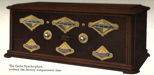
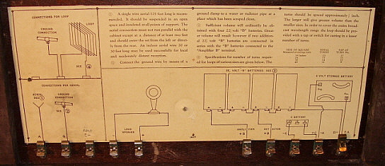
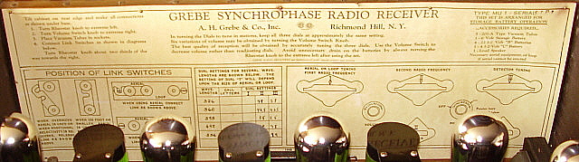
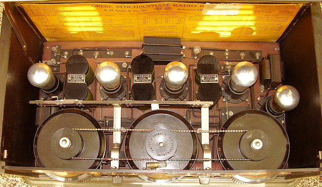
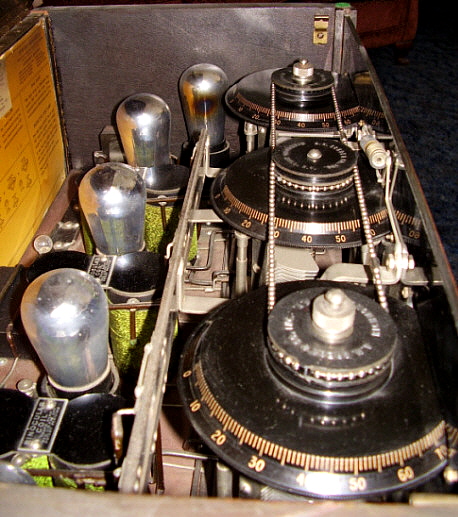
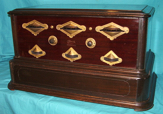
 MU-1 Early Production
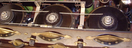
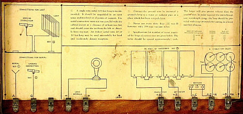
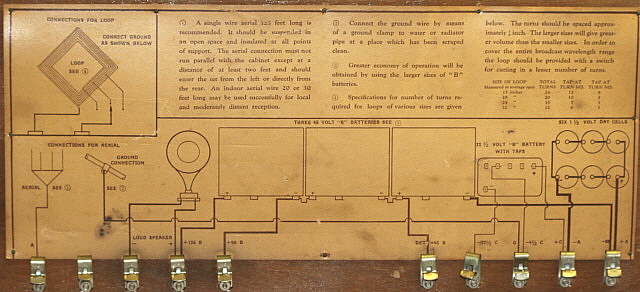
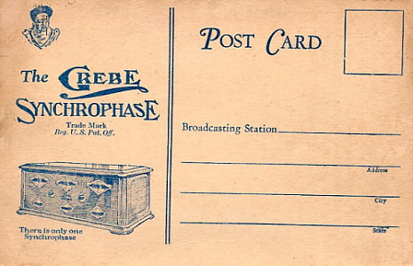
Aug. 1924 to mid-1925 - No Chain Drive, no Band
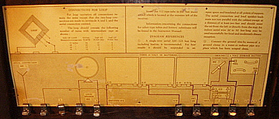
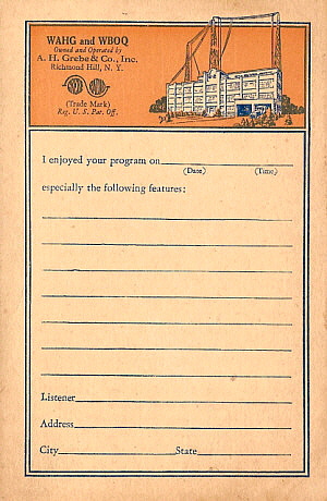
 Switch

BLYI - (one lid prop, early type)
CCBU -
(early type - no other details)
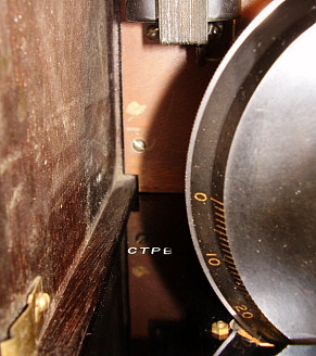
CTPB
- (VOL/FIL on R.E.,with Batt. Base option, 2LPs)
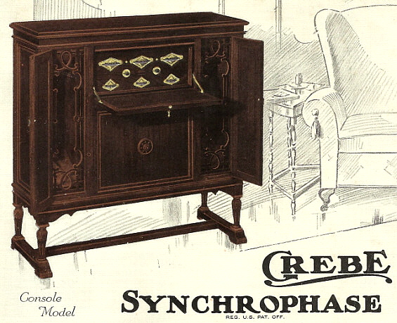
FWWC
- (VOL/FIL on R.E, from console model)
HVXD
- (early type - Battery Base option)
JRPI
 - (Two FIL R.E., early type)
JTRC -
(INCREASE only on Round Esc., 2 lid props)
LBCO -
(VOL/FIL on R.E.)
LYWA
- (INCREASE only on Round Esc., 2 lid props)
MPRI - (VOL/FIL on R.E., 2 lid props)
PNBU - (Early type, 2 lid props)
RXJA - (Early type)
STNU - (Early type)
TBRI - (Early type)
WJVX - w/ Batt. Base opt., 2 LPs)
WZJX - (Early Type)
ZDVC - (VOL/FIL on R.E., 2 lid props)
ZLXA - (Early type)


MU-2 Early Production
 No Chain Drive or Band Switch, 6 Tubes all UV-199

BNDU - No Chain Drive, six UV-199 tubes
HSGC -
No Chain Drive, six UV-199 tubes
VLZX - No Chain Drive, six UV-199 tubes
VYVA - No Chain Drive, six UV-199 tubes


 MU-1 Intermediate Production
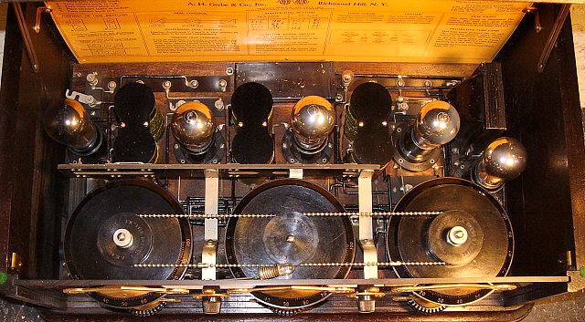
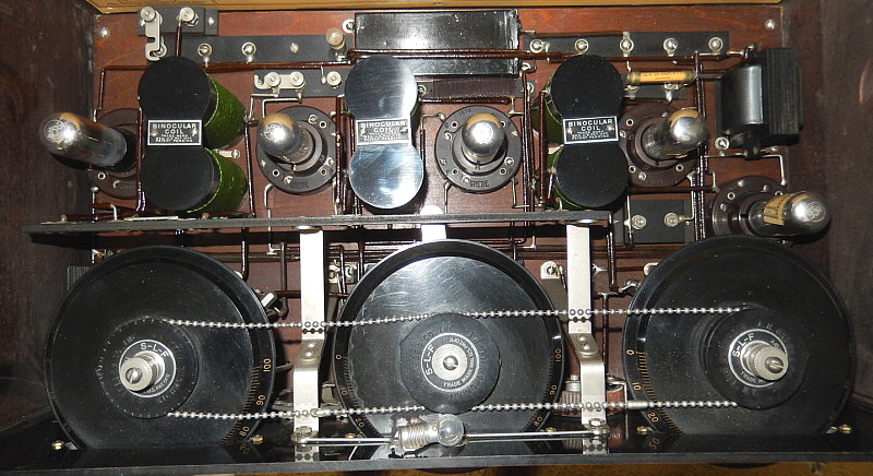
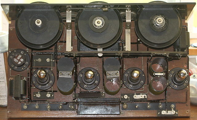
mid-1925 to mid-1926 - Chain Drive, Band Switch, both xmfrs the same size, +90VDC B+

BZNW - (Long B+, C- Caps)
CSPY - (Short B+, C- Caps)
FYJH - (Short B+, C- Caps)
GLYW - (Short B+, C- Caps)
GNPX - (Short B+, C- Caps)
JBBR - (Short B+, C- Caps)
JPSO - (std. mid-production)
KKKH - (std. mid-production)
LSRY - (std. mid-production)
MFSS - (Short B+, C- Caps)
NZCW - (std. mid-production)
PGNY - (Short B+, C- Caps)
PPSN - (std. mid-production)
PYLP - (std.mid-production, except has all Cushion Sockets)
RJNA - (Long B+,C- Caps, has 1926 Factory Upgrades)
SRSS - (Short B+,C- Caps)
TPTN - (std. mid-production)
VZLR - (Short B+,C- Caps)
WGXD - (Long B+, C- Caps)
XFGI - (std. mid-production)
YKYG - (std. mid-production, Short Caps)
ZYXG - (Short B+, C- Caps)


MU-2 Late Production
Chain Drive, Band Switch, 5 Tubes, both xmfrs the same size, Cushion Sockets, +135vdc B+

DMJA - Chain Drive, four UV-199 and one UX-120
SKHX
- Chain Drive, four UV-199 and one UX-120
WKYA - Chain Drive, four UV-199 and one UX-120


  MU-1 Late Production
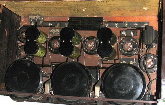
mid-1926 to mid-1927 - Large 1AF Xmfr, UX-112 tube, +135vdc B+ and Cushion-Sockets

BPZI - (UX-112, no other details provided)
BXVD
- (Late version)
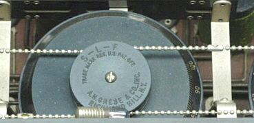
CCYI -
(All Cushion Sockets, S-L-F embossed)
CFFI
- (UX-112, no other details provided)
CMCP
- (UX-112, cushion sockets)
CRZD
- (No detailed data available)
DJJU
- (S-L-F embossed)
FSPG -
(All Cushion Sockets, S-L-F embossed)
HLLY
- (UX-112, cushion sockets)
HZFP
- (UX-112, cushion sockets, red/black mottled dials)
JMMT
- (All Cushion Sockets, S-L-F embossed)
JVFR - (All Cushion Sockets, S-L-F embossed)
KBZT - (All Cushion Sockets)
KVWY - (All Cushion Sockets)
LGYS - (All Cushion Sockets, S-L-F embossed)
LSHR - (All Cushion Sockets, mottled dials)
MFPA - (All Cushion Sockets, S-L-F embossed)
MHSA - (All Cushion Sockets, S-L-F embossed - Console)
MNZC - (Det Cushion Socket, S-L-F embossed)
NBLL - (All Cushion Sockets, late version)
NCSO - (Det Cushion Socket, S-L-F embossed)
NLCH - (All Cushion Sockets, S-L-F embossed)
NRFM - (All Cushion Sockets, S-L-F embossed)
NSHR - (All Cushion Sockets, S-L-F embossed)
PMMA - (All Cushion Sockets, no other data)
PVPA - (Det Cushion Socket, S-L-F embossed)
RDBD - (Det Cushion Socket, S-L-F embossed)
RGZL - (All Cush Sckts, S-L-F emb, Mottled Dials)
RPVA - (Det. Cushion Socket, S-L-R embossed)
SGDR - (All Cushion Socket, S-L-R embossed)
SLZR - (All Cushion Sockets, S-L-F embossed)
TNZS - (Det Cushion Socket, S-L-F Metal Rings)
TPBO - (Det Cushion Socket)
VCGY -  (Bayonet Sockets, S-L-F Metal Rings)
VNDX - (UX-112, large 1AF xmfr)
VVGH - (Det Cushion Socket, Older style Clutch Caps)
WGGN - (no details provided)
XBLW - (All Cushion Sockets, S-L-F emb'd, red/black mottled dials )
XCPT - (All Cushion Sockets, S-L-F embossed)
XNYB - (Det Cushion Socket, large 1AF xmfr)
XPDP - (post 8-26)
XVRN - (Cushion Sockets, large 1AF xmfr)
YFTI - (All Cushion Sockets, S-L-F embossed)
YPND - (post 8-26)
ZRDT - (Det Cushion Socket, S-L-F embossed)
ZXZL - (All Cushion Sockets, S-L-F embossed)

Nearing 100 reported Serial Letters and I don't see any pattern. It looks like the codes changed often, probably every week, to further obfuscate production. It doesn't look too good for decoding,...Please, still send in your Synchrophase serial letter combos and maybe something will reveal itself when more combos are logged,...but I doubt it.  - Henry Rogers, Oct., 2012.

NOTE: Sept 2022 - What is interesting to note about this collection of reported serial letter codes is that the quantity of "Late Production" radios reported is equal to all the other model versions combined. Certainly the late production versions of the MU-1 sound incredible when using +135vdc plate voltage on the UX-112A 2nd Audio Amplifier tube with -9vdc grid bias and driving a high-quality cone speaker. That's probably the reason for the survival of these versions. Owner's of the earlier versions either traded them in or sold them to buy the late production versions, especially if a performance demonstration was involved.

What do the Serial Letter Codes Indicate?

I think that trying to decode the Synchrophase serial letters via the serial letter log is a good illustration of an experiment that produces the opposite of expected results (like Albert Michaelson's "speed of light" measurements looking for the "ether wake.") I hoped to see a pattern in the MU-1 codes after a dozen or two combos were logged. Here we have collected nearly 100 combos that are tied to specific production indicators for date of manufacture and no discernable pattern has emerged. I doubt that anything can be determined about a particular MU-1 just from the letter code. That must have been the way Grebe wanted it.

To speculate on a reason for the obfuscation: It might indicate that Grebe was trying to protect themselves from a Neutrodyne lawsuit settlement that would be based on total production quantities. It seems possible that the Grebe management came up with an undecipherable code that allowed them to identify each MU-1 and MU-2 receiver while preventing anyone else from discerning any useable information from just the serial letters. If you had the code book, like the Grebe factory must have, you could identify any MU-1 or MU-2 but, without the code book, nothing specific could be determined about anything involving production quantities.

However, looking at the photograph shown to the right, which is the Grebe factory Test and Alignment Department, it's apparent that Grebe wasn't trying to hide the fact that the Synchrophase was a tremendous seller. Over one hundred Synchrophase chassis are shown in this photo. Each cart appears capable of holding at least twenty-five chassis and there are four carts in the area. Maybe advertising hype wasn't considered admissible evidence.


Restoration Hints for the Grebe Synchrophase Receiver

Restoring the Escutcheons - These are 24K gold covered with a lacquer overcoat for protection for early models and gold lacquer for later models. Neither type should be cleaned with anything abrasive. The gold-lacquer over the brass base metal is very thin and delicate. Almost any cleaner that involves rubbing will remove the gold-lacquer. Since it is so thin, most of the escutcheons have some corrosion showing through and will typically look "spotted" or "dark."

If your Synchrophase escutcheons are in good condition only use a soft paint brush to dust them. Never polish them with anything. Dusting lightly with a cloth is probably okay but don't rub.

If your escutcheons are green with corrosion or severely spotted then something has to be done. I have found that the escutcheons do very well when cleaned with Sodium Hydroxide which is easily available in "Easy-Off Oven Cleaner." EOOC will attack the corrosion and not bother the gold-lacquer that is remaining (if any.) Spray on the EOOC and let it set for about 5 minutes and then rinse the escutcheon in cold water. If it needs more corrosion removal, then spray again, wait 5 minutes and rinse. Only rinse with water - DO NOT RUB with anything - this includes rubbing with your fingers. If you rub, you will end up polishing the metal slightly and will ruin that flat gold finish that the EOOC gives to the escutcheons. Let the escutcheons air dry. You will notice when they are dry that if there was any gold lacquer present, it will still be there but with the corrosion gone and the base metal chemically cleaned, the overall appearance of the escutcheons is that they are excellent condition originals.

Reconditioning the Front Panel - The Synchrophase front panel is made out of bakelite. It is faux mahogany grain on the front and gloss black on the back. You'll find both mottled grain and linear grain faux in all periods of manufacture. The front of the panel was originally very glossy but over the years, cigarette smoke, finger grunge, various waxes and other contaminates usually have the panel looking flat, dark and with barely any character present. The Grebe Synchrophase lettering is filled with gold paint and usually that can barely be seen.

First, remove the front panel entirely because you can't clean it correctly and thoroughly with the escutcheons mounted. Remove all of the escutcheons. The dial and vernier knob escutcheons have nuts behind the panel so take care not to loose them. Once the escutcheons are off you will be able to see several screws that were hidden. The nickel-plated screws hold the tuning condensers to the panel so remove them. The black wood screws hold the panel to the wooden base, remove them. Removing the round escutcheons will also dismount the controls from the panel. The panel should now have everything dismounted from it.

Clean of the loose dirt with soap and water. Rinse well. Stubborn dirt and cigarette smoke residue can be removed with Glass Plus (DO NOT use Windex!) This will leave the panel clean and a little flat looking. Next use Wenol's Polish (English version of Semichrome Polish.) Polish one half of the panel at a time, the first time. Do a second polishing that does the entire panel. Polish with a good cotton cloth. You'll find the panel looks like new. The back gloss black seems to usually respond to just a good cleaning because it was never subjected to all of the dirt and grime that the front of the panel was.

When remounting the escutcheons you will probably remember that they were mounted with screws and nuts. The center-of-panel nuts are hard to access on the back of the panel. I use masking tape wrapped with the "sticky side" out around the tip of a long screw driver. The nut can then be held by the tape and guided into position using the long screw driver. Once the screw threads engage the nut will turn itself off of the tape. Continue rotating the screw and the nut will tighten up. Don't over-tighten.

The Cabinet - The Synchrophase cabinet is solid mahogany. The finish is medium to dark brown. The cabinet work is usually very good but since it's solid mahogany, cracks and splits are common. The cabinet is glued together with hide glue. If I have to repair splits or cracks, I use Franklin's Hide Glue. This isn't the real thing,...horse's hoofs and that sort of thing. Franklin's is synthetic hide glue and is the color of hide glue and sort of behaves like hide glue (except that it doesn't have to be hot) but it takes a very long time to set-up. Clamped joints usually take at least 12 hours before the clamps can be removed. The advantage is the color, which is amber, will blend into the wood and repairs are almost transparent. Franklin's Hide Glue bottles are dated because the shelf life is about 1 year.

If the cabinet is a little dirty with minor scratching, try boiled linseed oil rubbed onto the cabinet with a small cotton cloth. Do small areas at a time and work the boiled linseed oil into the surface. You can rub by hand also but this leaves your hands smelling like BLO for a while afterward (even after several washings.) Wipe as much of the BLO off as possible and then buff. The BLO will clean and will also leave a bit of a finished surface. It leaves the cabinet clean and with an original looking shine. You can apply BLO once in a while but remember it does build up a finish and really more than two coats aren't necessary.

If you are planning on refinishing a Synchrophase cabinet, you should have experience in duplicating older finishes. Most furniture restorers don't know how to do radio cabinets. Most of the time, even experienced restorers can only "come close" to duplicating the finish because we don't have the correct materials or the proper areas to work. Most early radio finishes were shellac but right around the mid-1920s, nitrocellulose lacquer became popular. My guess is that Grebe was using lacquer. Luckily, nitrocellulose lacquer is still available in most areas of the country. Besides the actual finish, the wood preparation is extremely important. Where most amateur refinishers fail is by not using "grain filler" - I don't mean shellac or whatever else the major hardware stores sell as "grain sealer." Grain Filler is actual fiber mixed in an oily paste that is applied to raw wood to fill in the pores. The correct type of Grain Filler is available from Star Finishes in Ft. Bragg, California and is called "Star Grain Filler." The paste is colored and be sure to use either dark brown or black - not neutral. Once grain filler is applied correctly, you will only need a couple of coats of lacquer and no pores will show. Sand lightly between coats and apply at least three coats of lacquer. Try to look at as many original cabinets as you can so you get the color close. Remember, in high altitudes the cabinets take on a grayish-greenish color because of the UV light fades the finish. Two of my Synchrophases were exposed to a lot of light and have the gray-green cast to the original finish. The factory, 1924-7 color was dark brown.

Radio Circuit Problems - Most battery operated radios are pretty easy to get going. Once good tubes are installed, many receivers will function with all original parts. It is dependent on how and where the radio was stored. Dampness causes the most serious damage. Also, expansion and contraction problems due to storage in unheated garages or sheds will damage the binocular coils (and also the glue joints of the cabinet.) The most common problem with all battery operated radios will be open audio interstage transformers and open grid-leak resistors

Interstage Transformers - The Grebe interstage transformers usually are 330 ohm DCR on the primary and 6.6K ohm DCR on the secondary. Though the ratio appears to be 20:1, the measurements are for DC Resistance (DCR) where as the actual ratio specified is the "turns ratio." Due to the greater lengths of wire needed to make each layer of turns, the secondary actually has much more wire (hence the greater DCR) to make the proper turns ratio. On early receivers, to accurately measure the primary DCR on the second AF interstage you must place the VOLUME control fully CW.

Unless you can find good condition Grebe replacements, you will have to either rewind the bad core or you can buy a Stancor A-53 core to replace the bad original. The A-53 is nothing like the original Grebe transformer because the DCR is so much lower. The A-53 turns ratio is 3:1 but because of the low DCR the bass response is lacking. If you want to have performance similar to original, you can also use a vintage interstage transformer that you can salvage the core from. Thordarson made some of the best audio interstage transformers at the time and nearly all of them found today are still in good condition. The Thordarson's will sound much better than the A-53 replacement core. If you have a bad Low Frequency interstage using the A-53 will defeat the LF xmfr's whole purpose. Try to find a good Grebe original for a replacement. If one can't be found then salvage a larger size vintage audio interstage, like a Rauland, or similar type. The Grebe transformers are riveted together requiring the rivets be drilled out to get the transformer apart.

Binocular Coils - The other common problem with the MU-1 has to do with the Binocular coil primary. This was wound with very fine solid conductor ~40 gauge wire. Any corrosion or physical stress like excessive expansion and contraction due to poor storage can cause this fine wire to break. When powering up your MU-1 using a good ABC eliminator, if you hear significant hum (you might also hear stations,) check the B+ at each of the RF amplifier tubes. Most likely, you'll find that one of the RF amplifier tubes doesn't have plate voltage due to an open primary on the associated binocular coil. You'll have to disassemble the coil which is difficult. The eyelets have pieces of TC soldered through both the primary and secondary forms to hold the primary form in position (along with a screw and nut on the other end of the coil forms.) These have to be removed before the primary can be extracted out of the secondary form. Once out, examine the primary carefully for breaks. You should find the break near one end of the coil. The original winding tension ends up breaking the coil at the ends due to expansion. Repair the coil and reassemble the binocular coil assembly and re-install the unit into the receiver.

B+, C- Bypass Capacitors - It's also possible that the B+ or C- Bypass capacitors could be shorted. This is not common but it does happen sometimes. Check these capacitors carefully. They should have no DCR and their capacitance should read on any sort of C meter. Value shown on QST schematic is .5uf but all the ones I've measured read around 1.0uf. Rebuilding the capacitor requires taking apart the metal can and removing the original capacitor, replacing with a new modern capacitor (or parallel combos to fit into the can) and then resealing the metal can. Sometimes the cans can be unsoldered but it requires a very large soldering iron. Cutting is an option and when the new capacitor is installed the cut end can be re-installed with epoxy and the can repainted.

VOLUME or TONE COLOR Shunt - Resistive Unit - This is a six-position, five section resistive shunt made up of a series of tapped wire-wound resistors. Ni-Chrome wire is used for the resistance with the wire being around 40 gauge. Moisture and expansion can damage the fine wire that is wound on a cylinder form. It's also possible that the connection to the arm of the switch can be broken with rough handling (the 40 gauge wire is exposed and easy to sustain damage.) Fortunately, the Ni-Chrome wire is not pure and it can be soldered to so repairs are not difficult. If a single resistance is open in the series another external resistor can be soldered to the back side of the contacts to complete the series value of the shunt. The resistance values are approximately 300 ohms (minimum setting and first tap) 50 ohms (second tap,) 150 ohms, 700 ohms, 1200 ohms and the last tap is not connected to allow disconnecting the shunt. The values do vary somewhat and are not critical as long as the minimum 300 ohm resistance is used and the progression from lower to higher values is maintained.

Grid-Leak Resistors  These resistors are almost always open. Measure any that you have and few are even close to what is on the label and most will measure infinity. 3 Meg is what Grebe specified. For a "quick fix" I use a NOS 2.5 to 3.0 Meg carbon resistor (NOS for the long leads) and place the resistor body inline with the glass tube and then carefully wrap each lead in a coil around the pointed end caps.  >>>

>>>  The grid-leak resistor body supports the carbon resistor and it is held in place when inserted into the grid-leak resistor mount. If I really want a nice repro grid leak, I make one out of an old open grid-leak. First, I pull the end caps off. I have a lot of .25" glass tubing around so if the glass breaks, I just cut a new one. What I really need are the end caps. I drill a .062" hole in each end cap point. Then I fit a 3 Meg carbon resistor into the new glass tube and then fit the end caps onto the glass tubing. I also place a piece of colored paper around the carbon resistor so the rebuild is hidden. Finally, I solder the end caps to the protruding resistors leads which holds everything together.

Clean with DeOxit - Before powering up the receiver, clean the three tuning condenser contacts to the rotor using DeOxit and lightly oil the main bearing for the rotor. This assures the condensers rotate easily and have noise free operation. Also, clean all of the tube socket contacts with De-Oxit and a stiff but small paint brush. Be sure to also clean the tips of the tube pins where they will fit against the tube socket metal contacts. This will assure a noise-free and proper operation of the tubes. On later models with the bandswitch, clean the slide contacts with a DeOxit saturated Q-tip.

UX-201A Tubes - "Burn-in" - When first powering up any battery-operated receiver you will notice that the sensitivity and volume are lower than expected. This is because the UX-201A tubes have probably been laying around and haven't had the filaments powered-up in decades. The UX-201A tubes have thoriated-tungsten filaments. The filaments are actually a pure tungsten wire that has an oxide coating (like a paste that hardens) that contains thorium. The thorium is in the coating to do a couple of things. First, thorium is a very natural emitter of electrons. Also, since the thorium readily emits electrons, the filament only has to be heated to an "orange" color for good emission. The older 201 tubes with pure tungsten filaments had to be "white hot" to emit electrons. This means that where the pure tungsten 201 tubes required 5vdc at 1A for good emission, the new 201-A, with thoriated-tungsten filaments only required 0.25A of filament current (at 5vdc) for the same (or actually better) emission. Unfortunately, with decades of inactivity, the thorium atoms that are part of the coating will migrate or sink down into the coating. The thorium has to be at the surface of the coating to emit electrons. Luckily, it's very easy to bring the thorium back to the surface. UX-201A tubes have to "burn in" but this process is almost natural and happens as you use your battery-operated radio. It takes a little bit of time for the thorium to migrate back to the surface and then the tube (or tubes) will operate with full gain. Usually about a half and hour at normal filament voltage will have the tube working properly. After the initial "burn-in" time, each time the tube is now powered-up, it will operate at full gain almost immediately.

Neutralization - If the MU-1 oscillates while tuning through strong stations the "balancing" capacitors need to be adjusted. "Balancing" was a term created by Grebe to describe the neutralization of the two RF amplifier stages. Obviously, "Balancing" helped to hide the fact that the Synchrophase was a Neutrodyne and subject to a patent infringement suit. Though it was called "balancing," it is really "neutralizing" and there is a section below on how to do it. Only do the neutralization adjustments after the tubes have "burned-in."
 

Schematics - Rider's Perpetual Troubleshooter's Manual Volume I has all three MU-1 schematics and also has the MU-2 schematic. These schematics are not in the Abridged VOL I-V manual. There was also a schematic published with the April, 1925 article in QST magazine by Ralph Batcher, who designed the S-L-F condensers. This is for the early version of the MU-1. It is shown below because it is easier to read since it is drawn more like modern schematics. Note there are a few errors, e.g., C1 should be C4, two C1s are listed, etc. Also, the values differ from measured original components.
 

Powering Up the MU-1 - You'll need a lot of accessories to power up any battery operated receiver. Here's what you must have available for the MU-1.

1. A Power Supply that will provide minimum 6.0vdc at a minimum of 2.0 amps. The current draw on the filaments is 1.25 amps and then if you have the dial lamp add another .15 amps. I like to have a little bit of reserve current available as you then aren't drawing maximum for the supply which usually ends up causing higher ripple on the A supply. Also note that a fully charged lead-acid A battery would have been at +6.8vdc. The Filament rheostat was designed to work with +6.8vdc down to about +5.8vdc when the A battery then needed to be recharged. With +6.0vdc, the Filament Control will be set somewhat higher than what is marked on the early Instruction Cards.

2. B Power Supply for +45vdc and +90vdc, very light current draw probably less than 50mA total on average. If you have the later MU-1 you'll also need +135vdc if you want to run the UX-112 audio output tube. You can also just run a UX-201-A tube and reduce the +135vdc to +90vdc and reduce the -9vdc bias to -4.5vdc.

3. C Power Supply or Batteries for bias voltage -4.5vdc on early MU-1 and -4.5vdc and -9vdc for later MU-1. I just use series AA batteries because bias current draw is practically nothing.

NOTE: Using Batteries for Power - You can use batteries entirely for powering up the MU-1 - that's how it was originally intended to be operated. It's expensive but the batteries for +45vdc are still available as "instrument" batteries. Also, Gates makes several types of "gel-cell" type lead-acid batteries in various amp-hour capacities. What you will find in operating the receiver on batteries is an extremely quite background noise with absolutely no perceptible hum. It's without doubt the best way to operate the MU-1 or any battery operated radio. However, expense and a finite battery life usually mandates using A-B-C eliminators instead.

4. Tubes - Five good condition UX-201A tubes for early receivers and four UX-201A and one UX-112 tube for later receivers.

5. Loud Speaker has to be either a horn speaker or cone speaker. These are high impedance magnetic speakers that have the solenoid coils directly in-line between the B+ and the audio output tube plate. You could use a modern speaker if you use the proper audio output transformer of about 5K to 10K Z ohms on the primary and 4 or 8 Z ohms on the secondary. Most enthusiasts use the correct vintage speakers to experience what the original users heard for sound quality.

6. Antenna must be at least 50 feet long but 125 feet long is what the MU-1 was designed for and works best with. Longer antennas don't necessarily work better. You can disconnect the selectivity link if the antenna is longer than 125 feet otherwise the first stage won't tune. Try to have the antenna as high as possible. Also, these early battery radios were generally designed to work into an "end-fed wire antenna, sometimes called an "inverted L." These antennas are generally physically short for the frequency (AM BC band) and present a high impedance to the antenna stage of the receiver. This is what the antenna stage was designed to work with for an antenna. Other types may not work as well, especially low impedance antennas like dipoles or vertical antennas.

7. Earth Ground was required when the receiver was operated on batteries. When using AC operated power supplies you can sometimes achieve ground via coupling through the power transformers and the house ground. This can work okay but generally a real Earth connection is better. Ground rods are almost a necessity since very few houses still have all metal cold water pipes to connect to for Earth ground. 

If you aren't already set-up for running battery operated radios, it can be expensive and a real hassle to acquire everything that is necessary. Unfortunately, everything mentioned is required to operate the MU-1 or any other battery operated radio. There is an inexpensive A, B and C power supply kit that is available from Antique Electronics Supply in Tempe, AZ. It is priced at about $55 plus shipping. It is built onto a wooden board but does work really well for the price. I use a Lambda 5vdc 4A supply that is adjusted to +6.0vdc and then I use a vintage RCA Duo-Rectron B Eliminator that uses an 874 regulator tube so the output voltages are constant regardless of load. I use two sets of three AA batteries for C bias requirements or an adjustable Lambda supply if other, higher bias voltages are required. A dual adjustable voltage bench power supply (RCA) can also be used if I really need a lot of different voltages.

Adjusting the "Balancing" Capacitors for Proper Neutralization - If, when you are tuning through stations, you hear an oscillation then the Balancing (neutralizing) capacitors need to be adjusted. The Neutrodyne circuit uses capacitive feedback between the plate and the grid of an RF amplifier stage to cancel out the vacuum tube interelectrode capacitances that allows oscillation to occur. With insufficient capacitive feedback the stage will oscillate because of the high gain of the circuit. With just a little more capacitive feedback the stage will be regenerative and have good gain and selectivity but might be somewhat unstable under certain conditions. With too much capacitive feedback the stage will not oscillate but also might not have enough gain to amplify the signal. In the Synchrophase (and all other Neutrodynes) the object is to have high gain with sharp selectivity and no oscillation while tuning through a strong signal. This is achieved with just a little regeneration but not too much since that would cause the stage to oscillate. To set the neutralizing capacitors, first the RF amplifier to be adjusted must only present its interelectrode capacitance in that stage. This is achieved by disabling the tube filament for the stage to be adjusted. A couple of small pieces of electrical tape on the tip of one filament pin is all that is necessary to disable the tube filament. IMPORTANT NOTE: Only tape one pin, leave the other pin able to make contact inside the tube socket. If you are neutralizing a later Synchrophase with the cushion sockets you will have to use a "dud" tube with an open filament and with no internal shorts between the grid, plate or filament. Be sure to check the "dud" tube for any obvious structural damage that would affect the tube's internal capacitance. The only problem with the tube should be an open filament. Also, make sure all of the supply voltages are close to the specified value and the receiver is operating correctly except for the neutralization adjustment.

You'll have to have the receiver out of the cabinet to access the neutralizing capacitors which are located on the tuning condensers for the first and second RF stages (the left most and center tuning condensers.) It's best to use a fiber non-conductive screw driver for the adjustments on early versions or a 1/4" open end wrench for the later versions (the bandswitch location prevents access by a screw driver on later versions.) Back the neutralizing trimmer capacitors out slightly which will reduce the capacitive feedback. Tune in a strong station near the middle of the tuning range. You will notice that the receiver will probably oscillate as you tune through the station but tune it in "on the nose." Next, install the tube with the disabled filament into the 2nd RF Amplifier socket. You will hear the station and some oscillation even though the stage is disabled. Increase the neutralizing capacitance trimmer on the center tuning condenser until you have greatly reduced the level of the signal and the oscillation. Now move the disabled tube to the 1st RF Amplifier position and move the good tube from that position to the 2nd RF amplifier position. You will hear the station again. Increase the neutralizing capacitance with the trimmer on the 1st RF stage condenser (left most dial) until the station signal just disappears. Now switch the RF tubes back so the disabled tube is again the 2nd RF amp. If you hear the station then increase the 2nd RF neutralization capacitance until the station just disappears. If you don't hear the station then back out the neutralization capacitor until you do hear the station and then increase the capacitance until the station just disappears. Remove the disabled tube and remove the tape from the filament pin and re-insert the tube into the socket. The station should be coming in very strong and as you tune through the signal (with any of the stages) no oscillation will occur. The RF amplifiers are now neutralized and adjusted for maximum stable gain.

The center dial and right dial should agree exactly. If not, tune in a station near the highest frequency end of the range (around 10 to 20 on the dials is good.) Note the setting of the center dial when all stages are peaked. Now, set the right dial to the same number as the center dial and then tune in the station exactly using the small trimmer capacitor on the right side tuning condenser. This setting is usually good across the tuning range if it is performed near the higher frequency end of the range. (Where the 1st RF amplifier stage tunes depends on the antenna length though it should be fairly close to the other dial settings - within a few divisions of the dial is normal after the receiver is neutralized.)

Grebe was always vague about adjusting the Balancing Capacitors and never published a procedure. They insisted that the factory settings were good for all variations in tube interelectrode capacitance. This was probably true, 80+ years ago. Nowadays, we have no idea who has "tinkered around" with the neutralization adjustments not really knowing how or what they do. It's an easy procedure to reset the neutralization so don't let the fact that the Grebe manual says it's not necessary stop you - adjust it properly and the Synchrophase will really be a sensitive and selective receiver afterward.


photo above: The neutralizing capacitors are located on the side of the tuning condensers. The capacitor on the tuning condenser to the left is a trimmer adjustment for identical dial indications on the 2RF and Detector stages. The center and right hand trimmers are for neutralization. This photo shows the early style chassis as viewed from the rear with tubes removed for photo. In the later versions of the chassis, the bandswitch blocks screw driver access to the neutralizing capacitors and a 1/4" open-end wrench must be used for adjustment.


Grebe Synchrophase MU-1 - Expected Performance Today

Early Version Synchrophase MU-1  CTPB

SET-UP - The Grebe MU-1 is regarded by vintage radio collectors as the "best performing battery-era five-tube TRF radio." This has been the standard belief among radio collectors about the MU-1 for decades. Let's state here at the beginning that since the MU-1 was evolving rapidly there is quite a difference between the early receiver and the later versions. Most important is the frequency coverage. The early receivers only tune up to a little above 1300kc. But with that limitation stated I should also mention the advantages. Most radio collectors that operate their MU-1 receivers don't use the chain coupled dial system. With the early sets, there is no chain coupling to bother with. Next, most collector-operators don't use the +135vdc and UX-112 audio output. Most just install a 201-A and run it on +90vdc with -4.5vdc grid bias. With the early sets, this is how they are operated anyway.

I powered up CTPB using a 6vdc 4Amp Lambda power supply for the A voltage, a vintage RCA Duo-Rectron B Eliminator was used to provide +45vdc and +90vdc B voltages. These are regulated voltages (using a 874 regulator tube in the Rectron.) I used three AA 1.5vdc batteries in series for the C bias voltage. I operated CTPB in the ham shack so I could use one half of the 135' inverted vee as the antenna. This was one side of the 43' feed line and one half of the antenna at 65' for a total length antenna (end fed wire) of 108'. This would have been considered a typical length antenna in the 1920s. Height was 30' at the highest point. The ground used was the ham station ground which is ground rods and radials - not your typical 1920s ground but it might be comparable to the old "cold water pipe" ground that had lots and lots of metal as a counterpoise and earth ground. The speaker used was a Rola Recreator horn speaker which is generally considered one of the loudest playing horns - not necessarily the "best sounding" but very loud, almost shrill sounding. Good for weak signals!

CTPB is a functional, all original example of the early MU-1. However, that doesn't mean I could operate it "as-is." As with almost all battery-operated radios, CTPB needed to have the UX-201A tubes "burned-in." The procedure is covered in the section above, "Radio Circuit Problems." I also cleaned the tube pins, the tube socket contacts and cleaned with De-Oxit the tuning condenser contacts. Additionally, I adjusted the neutralization per the procedure in the section above, "Adjusting the "Balancing" Capacitors fro Proper Neutralization." This assured that CTPB was operating at it peak level of performance.   

TEST -  During the daytime, only local stations can be tuned in but these consist of powerhouse 50KW stations in Reno or a 10KW station in Carson City that are very strong as easy to tune in. Weaker daytime stations might be the two AM stations in Fallon about 60 miles away. These are still easy to find and tune in properly. Nighttime operation is full of strong signals and the need for the Neutrodyne TRF circuit is realized when trying to separate these signals. CTPB does a fine job and there are two good tests in our area. First is to separate KKOH 780kc from KKOB 770kc. This is an extremely difficult test as KKOH runs 50KW and KKOB is in Albuquerque, NM. While I can receive KKOB fine, I can't entirely eliminate KKOH. The second test is to separate KPLY 630kc in Reno from KFI 640kc in Los Angeles, CA. This is an easier test (because KPLY isn't running 50KW) and the MU-1 separates these two stations with ease.

What is noticed in tuning the MU-1 is just how selective the two RF stages are with stations peaking at plus or minus one division. On the other hand the Detector tuning seems broad compared to the sharp selectivity of the RF stages but this is typical of most battery-era Neutrodynes. What is obvious when comparing the MU-1 to other TRF battery radios is the effect of the S-L-F tuning condensers. >>>

>>>  Usually, mid-twenties radios will crowd all of the BC stations above 1000kc into the top one-quarter of the tuning range. Not the MU-1. BC stations are evenly spread out over the entire dial and even though the top frequency tuned is around 1300kc, the stations in that region of the band are not relegated to just a few dial divisions.

Sensitivity is the best of all of the battery operated TRF-Neutrodyne receivers. In just a few minutes of operation, I had tuned in KFMB in San Diego, KOA in Denver, KSL in SLC and many other power house stations at about 500 to 1000 miles distance. Many weaker stations could also be tuned in but station identification is not mentioned very often in broadcasting these days. I would estimate that 1500 miles distance would be easy for the MU-1 on almost any night when setup as CTPB was for this test.

Sound quality is of course dependent on the speaker. I was using a Rola Recreator horn speaker that, while very loud, is not a particularly mellow sounding horn. The MU-1 CTPB was able to drive the Rola quite loud at only about 2 or 3 on the VOLUME control with the FILAMENT control set at the recommended "4" which is about +4.7vdc on the tube filaments with a +6.0vdc A supply. If you're looking for an accurate sound representation of what the MU-1 sounded like when tuned to a high power, high quality broadcast station in the twenties, you'll have to use a good quality horn speaker. Stay away from any of the horns that use the ferrous-diaphragm magnetic-coupling, like Atwater-Kents, RCA UZ-1325, etc., and use a direct-driven diaphragm horn speakers such as the Rola Recreator, a Baker-Smith "Sylfan", the Western Electric 10-D, a Westinghouse FH, a Magnavox M-4 (direct-driven mica diaphragm) or the Maganvox R3-B (Lo-Z voice coil with output transformer.) These horns play at least twice as loud as magnetic-coupled diaphragm horns and allow easy reception of DX stations.

Mid-Production MU-1  RJNA  with Audio Upgrades

SET-UP - The later MU-1 has the advantage of the extended frequency coverage to allows tuning up as high as 2000kc, or the top of the 160 meter ham band. This, of course, allows the operator access to all of the AM BC stations above 1300kc. The MU-1 we are testing is MU-1 RJNA which started out as a typical mid-1925 upgrade receiver. Probably sometime in 1927 or so, the owner wanted his MU-1 to have some of the later upgrades. This MU-1 has Grebe Factory installed UX-112 audio output, Grebe low frequency 1st AF transformer, wired for +135vdc B+ and -9vdc C-. Additionally, the Factory replaced the bayonet socket on the Detector tube with a Grebe cushion socket. All of the other sockets are still bayonet-type. So, this is a close as I can come to the latest of the MU-1 production. RJNA has everything except the capacitor TONE COLOR control and all cushion sockets.

MU-1 RJNA was powered up and run with all of the same accessories as MU-1 CTPB with the exception that +135vdc, along with -9vdc grid bias, is required for the UX-112 audio output tube. The RCA Duo-Rectron provides +135vdc regulated so hook-up only required an extra connection to that terminal and also an additional three-pack of AA batteries to add to the existing three-pack to create a -9vdc and -4.5vdc C- bias voltages.

I wanted to see if I could notice any significant audio improvement with RJNA since it had all of the upgrades necessary to operate like a late version MU-1. With that in mind, I replaced the Rola horn speaker with a Peerless Reproducer cone speaker. The Peerless is without doubt one of the best sounding Hi-Z magnetic cone speakers available. Its "cathedral" style wooden cabinet has made it a very popular collector's speaker but its high-quality reproduction is what we are interested in for this test.

I have had MU-1 RJNA for about 15 years. It was brought to the museum to be sold to us along with its truly original Grebe Synchrophase Manual (yes, you can tell the difference between the originals and the excellent reproduction that Radio Age produced in the early 1980s.) After the purchase, I did a cosmetic restoration and checked everything for operation and put the receiver in a display case. I never put RJNA into operation at that time. So, I had to actually do a few things before the test to assure that RJNA was operating correctly. I cleaned the rotor contacts on all condensers, lubed the rotor bearings, cleaned the tube socket contacts and tube pins, cleaned the bandswitch contacts and tested the two bypass condensers. I performed a complete power-up test and found that the receiver didn't operate very well at all. I found that the 2nd RF amplifier tube socket had a severely bent pin contact that didn't allow the tube filament to operate. I had a replacement original socket so the defective one was replaced. Still, the receiver didn't tune correctly with the tracking between the stages off by 10 to 20 divisions on the dials. They should agree within a few divisions. Measuring the RF amplifier plate voltages revealed that the 1st RF amplifier tube didn't have plate voltage and this was due to an open primary on the associated binocular coil set. I had to remove the coil set and disassemble it to repair the primary winding. Then reassemble and re-install. Finally the MU-1 began working as expected with loud signals and tracking that was within a few divisions on all dials. I then set the neutralizing capacitors per the procedure elsewhere in this article. Now, MU-1 RJNA was ready for a testing session.  

TEST - The first thing noticed is that the Chain-drive is somewhat of a nuisance. The narrow  Neutrodyne selectivity requires that the two RF stages be in accurate tune and the Chain-drive gets you close on local stations but you'll always have to slightly "tweak" the adjustments of the two RF stages for DX stations. You'll find yourself always lifting the lid to loosen or tighten the knurled nuts to engage or disengage the chain-drive depending on what you are trying to receive. Also, the Chain-drive requires using the large center dial for tuning as the vernier drive will not turn all three dials coupled together. You can use two hands and turn the center and right hand verniers and this will tune all three dials simultaneously. It's easier to just loosen the knurled nuts on top of the sprockets and tune all of the stages individually. At the time the Synchrophase was upgraded, single-dial tuning was considered very desirable (or maybe just an advertising gimmick.) Today, on the MU-1, it's virtually useless.  NOTE: It has been reported by a few MU-1 enthusiasts that their chain-drives work great and can be driven by just the center vernier. This requires exceptional mechanical condition of all parts plus thorough cleaning and lubrication of the condenser bearings. The bottom chassis board can't be warped as this will affect the mechanical alignment. Let's just say that most MU-1s will have some trouble driving all three dials coupled together but there will be exceptions.   >>>

>>>  The bandswitch increases the tuning range of the MU-1 from a high of about 1300kc up to around 1900kc. You can actually tune in 160M hams. It also allows tuning in the region of 1600kc to 1700kc where more recent broadcasters have been placed. The effect of the S-L-F tuning condensers is even more apparent in the higher frequencies. The actuation of the bandswitch is  somewhat cumbersome being located at either end of the central tuning dial but the slide switch does function fine.

So, for the mid-1925 improvements, the Chain-drive was not really very usable unless you only listen to local stations. The increased tuning range with the band switch addition really improved the MU-1 and gave it one of the widest tuning ranges of the mid-1920s battery sets.

The mid-1926 upgrades greatly improved the audio reproduction. Since we are using a Peerless Reproducer cone speaker, which will sound very different than a Rola Recreator, the comparison will be how pleasing the sound is from the Peerless and how loud does it play using the +135vdc B+, the UX-112 audio output tube and what is the effectiveness of the TONE COLOR control.

Wow! That's the impression when powering up a 1926 MU-1 after running a 1924 version. The audio power is very apparent and so is the increased bass response. It's easy to drive the Peerless to extremely loud and because it's a cone speaker, it doesn't rattle too much (like some cheap speakers do.) The modern AM Broadcast stations do tend to overdrive the Peerless so high volume will result is some bass distortion. Bass response improvement is dramatic after listening to the 1924 version. Don't expect modern, "booming" bass response but the improvement over the earlier MU-1 and Rola horn is very apparent. The TONE COLOR control does noticeably change the audio frequency response with position 1 sounding almost muffled and position 6 (open) almost flat. Usually, the MU-1 sounds best (with the Peerless) with the TONE COLOR at about 3. When receiving a weak station it's better to have the TONE COLOR at about 6 for better intelligibility. Certainly, we are using one of the best sounding cone speakers, the Peerless Reproducer, known for its mellow reproduction. Other cones also have their advantages and their disadvantages. The cone speakers with actual enclosures seem to be better sounding, although the Radiola 103 is a nice sounding cone with no enclosure. The Radiola 100A metal mantle-clock shaped cone speaker is also a nice sounding unit. Unfortunately, many of the beautiful, art-styled cone speakers have anemic magnetic drivers and sound awful. (Although I didn't have a Western Electric 540AW 18" cone speaker at the time I did these tests, nowadays I have been using a very good condition 540AW with a FADA 8 and I can say that it is a very nice sounding cone speaker that can be driven really hard and still sound good. I'm sure it would sound great on a 1926-7 MU-1.) The later MU-1 is so sensitive that the Long Antenna link had to be opened for local stations when using the 103 ft antenna. I performed the same selectivity test on RJNA and found that since the Long Antenna link was open, it was easy to separate KKOH 780kc Reno from KKOB 770kc Albuquerque. 

So, the final verdict on the later version MU-1 is that the Chain-drive is almost useless but the frequency coverage extension with the bandswitch was a nice improvement. The 1926 audio upgrades were THE major improvement for the MU-1 providing great audio reproduction. I know most collector's don't bother running their MU-1s with the UX-112 and +135vdc plate voltage but, if you have a high quality cone speaker, give it a try. I was very impressed.

In the two reviews above, I tested the early version of the MU-1 and compared it to the test of the 1926 upgraded version but this leaves out the 1925 upgraded version. I have MU-1 SRSS that is a 1925 version of the MU-1. Although I haven't run SRSS specifically for this article, I have owned it since 1975 and have operated it many times in the past. If you are looking for the extended frequency coverage without all of the upgraded audio improvements, then the 1925 version is for you. You can run all UX-201A tubes with +90vdc maximum B+ and you will only need one -C bias voltage. Also, a horn speaker is appropriate for the 1925 version and this version will sound great using a Rola or other high quality horn. Additionally,  you have the extra conveniences of the dial lamp and the fuse lamp along with the dial chain-drive. So, the 1925 version of the MU-1 has many advantages for the collector/operator that wants a very sensitive and very selective receiver without all the hassle of the audio upgrades that require more voltages and a different tube for the audio output stage.

Hopefully, these tests will help you decide if you'd rather have the early version MU-1, a mid-production model or a later version of the receiver - but, you'll probably be like me and want to own and operate all of the different versions!

 
Conclusion - In 1927, the MU-1 was rapidly becoming obsolete. Many "high quality" Neutrodynes were on the market that performed as well as, if not better than, the Grebe MU-1 (the incredible FADA 8, for one, though it was twice the cost of the MU-1.) Grebe did introduce a single dial version but it wasn't produced in any quantity. By late 1927, AC power operation was the latest offering from the manufacturers. Grebe responded with the Synchrophase AC-Six, a thoroughly different looking radio receiver than the old MU-1. For those in areas without AC power, Grebe offered the similar-looking Synchrophase Seven battery operated receiver. Later, for a nominal sum of $55, the factory would convert a Seven to AC operation. In the end, Screen-Grid tubes sets and eventually a few superheterodynes were produced before Grebe went bankrupt, a victim of the Great Depression. Grebe had every intention of reforming the company but he died, at age 40, from complications following surgery.

Without a doubt, the most often seen Grebe radio produced is the Synchrophase MU-1. After all, over 150,000 of them were built between mid-1924 and mid-1927. It is a good example to represent Grebe, a company that could stay competitive throughout the twenties when radios were being produced and sold in incredible quantities by hundreds and hundreds of manufacturers. Great performance and great looks,...that's the Grebe Synchrophase.

References:

1. Grebe Synchrophase Manual - covers 1926 version. High-quality copies were published by RADIO AGE (Don Patterson) in 1983. Many of these reproduction manuals can still be found on eBay. The only difference between the originals and the copies is the original uses a small representation of the MU-1 diamond escutcheon to end each section and these are colored gold in the original manuals while they are black in the copies. Also, Don had to add the reprint info on the inside back page.

2. Grebe Radio 1925 Advertising Brochure - Covers early versions of the MU-1 and MU-2. Multi-color and high-quality photos and artwork. This brochure states that the escutcheons are "dull 24K gold covered." Information on WAHG and many earlier Grebe CR-series models.

3. Rider's Perpetual Troubleshooters Manual VOLUME 1 - schematics from 1924, 1925 and 1926 for the MU-1 and schematic for the MU-2 from 1926.

4. Radio Age, Don Patterson - multi-part article on A. H Grebe from the 1980s.

5. Radio Manufacturers of the 1920s, Vol. 2, Alan Douglas - history on A. H. Grebe & Co., Inc.

6. The Radio Manual, George Sterling - neutralization of TRF stages

7. QST April 1925  - Ralph Batcher article on the Grebe Synchrophase

Henry Rogers - WHRM  ©  December 1, 2010,  July 2016 - added MU-2 late version info,


Return to Home Index


Radio Boulevard
Western Historic Radio Museum

 Vintage Radio Communication Equipment Rebuilding & Restoration Articles,

 Vintage Radio History and WHRM Radio Photo Galleries

1909 - 1969

- 60 years of Radio Technology -


This website created and maintained by: Henry Rogers - Radio Boulevard, Western Historic Radio Museum © 1997/2023