Radio Boulevard
Western Historic Radio Museum

Rebuilding and Operating the AN/GRC-19 Transmitter-Receiver

GRC-19 General Information,   T-195 Basics,
Powering up the GRC-19,  T-195 Commonly Encountered Problems,
PP-1104-C Basics,   R-392 Basics,
R-392 Commonly Encountered Problems,
Hints and Suggestions for Operating the GRC-19


By: Henry Rogers WA7YBS


photo right: This Stromberg-Carlson ad from the fifties pays homage to the U.S.Army's use of the GRC-19 and also to the Collins engineers who designed it

Restoring the AN/GRC-19 to operational condition is considered something of a paramount challenge by most military radio collectors and enthusiasts. Most fans of the GRC-19 are intrigued by the T-195 transmitter's ultra-complex, motor-driven, completely auto-tuned design, not to mention the fact that it was designed by Collins Radio Company. On the other hand, the GRC-19 combo weighs over 200 lbs and the blowers that keep the external anode tubes cool give the impression that the transmitter is about ready to take off and become airborne. Then there's that T-195 complexity that has prompted more than one collector to say, "If your T-195 transmitter doesn't work, get rid of it and find another one that does." The companion, Collins-designed R-392 receiver has droves of fans and is much more popular as a "stand alone" receiver rather than as part of the GRC-19 combo. This article details both the T-195 transmitter and the R-392 receiver that, when paired together, become the AN/GRC-19. Hints and suggestions on repair, rebuilding and operation are included. Also, I've thrown-in a short section on the popular PP-1104-C power supply which is used by many military radio enthusiasts to power their high-current demand dynamotor-driven gear. - H. Rogers  Sept. 2013
 

Rebuilding and Operating the AN/GRC-19 Transmitter-Receiver

General Information - Around 1951, the U.S. Army needed to update its portable communications equipment. Portable in post-WWII late-forties had been limited to the behemoth SCR-299 and 399 units that consisted of a truck loaded with a BC-610 transmitter and BC-342-344 receivers along with pulling the trailer-generator to operate the gear. On the other end were the small portables such as the BC-699 or sometimes the BC-191. With the Korean War starting up what was necessary was a portable transmitter-receiver combination that was a modern design, operated at a moderate power level and could be used outdoors or even deployed via parachute to remote locations. The result was the GRC-19, a set-up that consisted of the T-195 transmitter - an autotune unit capable of around 100+ watts of carrier power - and the R-392 receiver that was based on Collins' the highly successful R-390 receiver.

Since the transmitter-receiver had to be portable, it was designed to operate exclusively on +24vdc to +28vdc. Since the GRC-19 was going to be exposed to the weather in many types of open vehicles, the entire system had to be somewhat "weather proof." To allow the receiver to be completely sealed with no ventilation and thus, to have the receiver run as cool as possible, no voltages higher than +28vdc are used in the R-392. The T-195 transmitter used forced-air cooling for the three external-anode tubes used in the PA and Modulator so an oil dampened air filter was provided for the intake but this did not "water proof" the transmitter while it was in operation. It was possible to seal the intake and exhaust ports when the transmitter was not in use to aid in the weather-proofing. Additionally, many times the military was going to have to "drop" communications gear from the air, so the R-392 and T-195 had to be "ruggedized" to be able to survive this type of deployment for portable field use. The air-drops were usually fully-equipped Jeeps. Fred Johnson, Collins' head mechanical design engineer for the T-195, indicated that one of the "endurance tests" for the T-195 design was for its survival of a drop from twenty feet - impressive!   

The GRC-19 was commonly used on Jeep-type vehicles up to larger "command car" types. A whip antenna was used if operation was going to be mobile but, if the vehicle was going to be parked in one location for longer than an hour and a half, a dipole antenna was usually erected since power output was much better with this type of antenna.  

The GRC-19 was capable of FSK transmission and could be set up to operate portable RTTY. This required an external FSK unit that connected to the MO OUT and the FSK IN connectors on the T-195 transmitter. It was also necessary to use a RTTY TU connected to the R-392 IF OUTPUT to operate the RTTY printer. Most of the RTTY uses seem to be early in the GRC-19's history and the mode isn't even mentioned in later manuals (by the 1960s.)   >>>

photo above: The AN/GRC-19 on the MT-851/GRC-19 vehicular shock mount. Also shown is the LS-166 weather-proof loudspeaker, the H-33 handset. The interconnect cables between the T-195 and the R-392 provide power to the receiver along with transmit-standby function. The small interconnect cable near the meters provides the antenna input for the receiver. I actually don't use the LS-166 speaker and prefer to use a H-301 headset which reduces the T-195 blower noise to a whisper. I don't use the Euro-made Orlem H-33 handset shown either and prefer using an Electrospace Corporation version made in the USA in 1962. Also, note the short coax jump next to the power connector. This is a convenient way to operate Voice on a T-195 that is set up for RTTY. See section below "FSK vs Voice Operation Set-up" for more details.

>>>   It was also possible to operate the GRC-19 remotely using the AN/GRA-6 Remote Control Group. This consisted of a Local Control box, a Remote Control box and up to two miles of two conductor wire cable between the Local and Remote boxes. Only VOICE could be used in this set-up that allowed the GRC-19 to be set up in a location best for communications and then to allow the radioman to find a more secure location to operate from. 

Although the GRC-19 is thought of as an "army radio," the "AN" designation implies "ARMY-NAVY."  Additionally, the Air Force had its own technical manual designation (TO 31R2-2GRC19-11) so the GRC-19 was probably used by all branches of the military for various purposes from the early 1950s up into the late 1970s though today it is mostly regarded as an "Army Radio."


photo left: GRC-19 as shown in the operator's manual


T-195 Transmitter Basics

General Description - The transmitter for the GRC-19 combo was the T-195, designed by Collins Radio Company around 1951. The T-195 is a 100+ watt carrier output transmitter capable of AM, CW or FSK transmission on frequencies from 1.5mc up to 20.0mc. Seven preset frequency channels are available along with a Manual Tuning position that can also serve as an eighth preset channel. The transmitter consists of a main frame with modules that are secured with captive screws to the bed plate. Each module has cables that plug into various Amphenol-type sockets and inter-module "button" or "slide" contacts to provide power and signal routing. The circuit uses a PTO (Permeability Tuned Oscillator) to generate an oscillating signal that is fed into an Exciter-Multiplier module that mixes the signal to the correct output frequency. As expected from Collins, the PTO and the Exciter-Multiplier are entirely permeability tuned with the Exciter-Multiplier using a slug carrier rack and RF transformers that are very similar in operation and appearance to the R-390A RF transformer tuning system. The Exciter-Multiplier has a 5763 output tube that drives the PA module that has a single 4X150D external anode type RF amplifier output tube along with a built-in discriminator circuit to control the automatic Plate tuning of the PA tube. The Modulator module contains the speech amplifier and the push-pull 4X150D modulator tubes and the modulation transformer. The output loading and matching is all accomplished automatically by using a Discriminator module, a Servo Amplifier module, an Antenna Capacitor module, an Antenna Inductor module and the Output Capacitor section that is part of the Main Frame. A total of 21 tubes are used in the T-195 which features complete autotune capabilities and uses a Veeder-Root type of mechanical-digital readout for the transmitter frequency. Modes available were AM VOICE, FSK or CW. Additionally, the T-195 could be set-up as a RELAY station by using the R-392 receiver audio to drive the T-195 audio input and thus "relay" an incoming signal.

1952 T-195 Transmitter built by Stewart-Warner for Collins Radio Company. This particular T-195 has been upgraded to have the +HV Solid State power supply rather than the original dynamotor. After this modification the transmitter was usually designated as T-195A.

T-195 Circuit Details - Inside the T-195 are several small DC motors. Two motors operate blowers to provide forced air-cooling for the three 4X150D external anode tubes used in the PA and Modulator (4X150D - the "D" version must be used since it has a 26.5vdc filament.) Another DC motor is the autotune motor which operates the channel preset frequency selection. The Output Capacitor selection uses a DC motor. There are three AC servo motors (operating on 115vac 400~) to control the loading and tuning operation which is also part of "autotune" in that the T-195 does "automatically tune" itself to whatever antenna load is connected. This "tuning" is accomplished by using a discriminator module that creates error voltages based on phase and load sampling (of the PA) which are then amplified to drive the servo motors. When the error voltages are zero then the transmitter is "tuned" to the antenna load. On early T-195s, two dynamotors are internal to the transmitter with a HV dynamotor providing +1000vdc and a LV dynamotor that supplies three voltages, +250vdc B+ along with -45vdc for bias requirements and 400 cycle 115vac. Additionally, there are several thermo-switches to prevent overheating along with relays and interlocks galore (there are over 15 relays used in the transmitter.) The T-195 is very complex because of its autotune capabilities and because it was designed to essentially be used by operators with no particular skill or training, thus the transmitter had to basically "take care of itself." Several of the thermo-switches will shut down the transmitter if things get too hot. A few minutes "cool down" is normally required to let the thermo-switch reset (you should also correct the problem that caused the over-heating in the first place.) The T-195 is robustly built so reliability was usually pretty good. The photos below show the densely-packed modular design and the complexity of the T-195.


A look at the T-195 upper deck as seen with the rear cover removed. On the left side is the PTO and Exciter-Mulitiplier. Clustered in the center are the Discriminators, Antenna Tuning Capacitor and inter-connecting sockets. On the right side is the Antenna Inductance module (note the motor driven ceramic coil form for the ribbon wire variable inductance.) In front of the Ant. Ind. module is the Output Capacitor selector. Note the small motors in the various modules. Also note the LV dynamotor (center bottom, with the vents.)


Looking at the underside of the T-195 (rear cover installed.) At the upper left is the Modulator module. Note the yellow captive screws that indicate that this small chassis is removable to allow installation of new modulator tubes. The black cylinder is the +HV SS PS. The module in the center is the Servo Amplifier. The RF PA module takes up most of the right side of the bottom deck. The air variable is the PA plate tuning capacitor that is servo motor driven during the autotune cycle.

T-195 Meter Situation - Like the R-390A receivers, the T-195 transmitters are often found without the meters installed. This was due to concerns about the radium coated meter needle and the radium coated scale used in both meters. Usually the meters were removed when the transmitter was decommissioned and was going to be offered to the surplus market. Meters were removed and disposed of in some prescribed manner that satisfied the powers concerned. Whether or not the meters were removed carefully varies from transmitter to transmitter. Sometimes the connecting wires were cut too short and you'll have to add wire to what's left in order to have sufficient length to connect the meters back into the circuit.

Chances are after you've found a T-195, you'll begin to look for the meters. The AUDIO LEVEL meter is easy to find because it is exactly the same meter used as the LINE LEVEL meter in the R-390A receiver. These show up with some regularity on eBay. The T-195 TEST METER is a different story, however. Though this meter is the same style as those used in the R-390A, it has a unique scale only found on the T-195 TEST METER meter. You can look for the original type meter but it will be a long search. It's easier to modify a meter of the correct style to replace the TEST METER. A scale can be made as an overlay and it can be based on the drawings of the meter in the manual or by looking at the photo to the right. Be careful in selecting the replacement meter. There are examples available of the correct style of meter that won't have the radium scales or needles and these are the type to find since you'll be disassembling the meter for the new scale. Special tools make meter disassembly easy and if you don't have them you'll have to be very careful not to damage the meter during disassembly. As to FS current, most meters are around 0.8mA FS but it does vary. You'll have to do some testing of prospective meters. When installed in a working T-195, the TEST METER will show the input DC voltage level (BATTERY) at mid-scale with +28vdc input voltage to the T-195. This would be a good test for a prospective meter. The PA GRID current will usually show well over 200 on the scale when the Exciter is aligned and PA CATHODE current will show around 300 on the scale when the transmitter is loaded. Readings called out in the manual are not specific and just say the reading should be "over" a certain level on the meter.

Powering the T-195 - To power-up the T-195 requires +28 to +29vdc at 40amps and this was generally provided by vehicular battery-charger systems. With early version T-195 transmitters (with two dynamotors) even vehicular operation did require the engine RPMs to be kept fairly high since the transmitter required so much current to "start" the HV dynamotor (the manual states that 250 amps are required for 0.5 seconds to start the dynamotors (PTT application in FSK/VOICE or initial switching to CW mode) with the supply voltage being able to drop down to a low of +14vdc and still be enough to get the dynamotors to start turning (at which point the "starting current" drops rapidly.) Though the front panel power input is marked "+24vdc" the T-195 doesn't run very well at that low of input voltage and prefers at least +28vdc (and the data plate is marked "+28.5vdc @ 40A.") If the transmitter is run just off of two series connected 12vdc car batteries the input voltage will probably be too low for proper operation of the autotune. Basically, at low input voltages the autotune will take too long to finish "tune and load" before the PA cathode thermo-switch opens. It's better to run the transmitter on a high current power supply like the PP-1104 that can supply +28.5vdc (adjustable) at the high current required. Many of the T-195 operational problems that were due to the horrendous starting current (and even the operational current with the dynamotors at speed) were somewhat abated with the later T-195A and T-195B versions. Also, when operated as a GRC-19 with the R-392 receiver you will be adding another 3 to 4 amps for the receiver. This pushes the current requirement for the GRC-19 up to almost 45 amps for the early versions.  More info on the PP-1104 in a section below.

photo left: The Modulator module showing the speech amplifier section in the lower part of the photo and the modulation transformer and the modulator tube sockets in the upper part of the photo. Note the yellow headed captive screws. These indicate that this smaller sub-chassis is removable to allow modulator tube replacement.


photo right: This shows the sub-chassis dismounted from the main Modulator module for tube replacement. Note that the sub-chassis is connected to the module with a flexible cable. The fiber collars around the tubes direct the airflow through the cooling fins of the tubes. Note the three smaller access holes in the side of the main frame. These provide access to adjust the Modulation level, the Clipper function and the level of the Side Tone output.

FSK versus VOICE Operation Set-up - Initially, when you pull your T-195 out of its case, note the routing of the two yellow coax cables the come from the PTO and from the Exciter module. If the PTO coax is connected to the jack that is next to the Antenna Tuning Capacitor module then the PTO is connected to the MO OUT BNC connector on the front panel. You will then also find that the other yellow coax that is plugged into the Exciter is also coming from the front panel and from the FSK IN BNC connector. This is the typical set up for the T-195 to operate RTTY. There was an FSK accessory that connected to the MO OUT and the FSK IN and allowed the T-195 to run FSK for RTTY.

For VOICE and CW operation you should route the cables as shown in the photo to the left. This shows the PTO coax cable routed directly to the Exciter module coax connector. Then route the cable from the FSK IN BNC front panel connector to the coax input connector that is located next to the Antenna Tuning Capacitor module. This will in connect the MO OUT to the FSK IN which is a convenient way to terminate the plug end of the FSK IN cable. Be sure to route this cable through the hole provided in the frame. If you route the cable over the frame you won't have enough clearance to fit the transmitter into the case.
 
You can also just leave the T-195 set up for RTTY and connect a short coax jumper between the BNC connectors MO OUT and FSK IN on the front panel. This accomplishes the same thing however the chained BNC "caps and chains" will dangle loose with this method. The VOICE set up described above allows the BNC caps to be installed on the BNC connectors.

T-195A and B Versions - Late in the military's use of the T-195 (just before the Vietnam War era) there was a retrofit to convert many of the T-195 transmitters to use a solid-state power supply to replace the +HV dynamotor. The replacement power supply is shaped somewhat like the original dynamotor but has no vent holes or any moving parts. This reduced the total T-195 transmitter current required down to about 32 amps but the big reduction was in the +HV dynamotor "starting current" that no longer was required. Later, a solid-state power supply for the +LV dynamotor was also available. Still later, these SS power supplies were installed from the factory and these models will be designated as the T-195A or T-195B. Although it's likely that the A version has just the +HV PS and the B version has both, I can't find any documentation that states this is the case.

Current Requirement Breakdown - Here's a breakdown of the current draw for the various components.

T-195 with +HV Dynamotor installed = 12 Amps in Stand By, 40 Amps Key down (250A instantaneous starting I )

T-195A with +HV SS PS = 12 Amps in Stand By, 32 Amps Key down (LV dynamotor starting current only)

T-195B with +HV and LV SS PS = >30 Amps Key down (no dynamotor starting current)

R-392 Receiver = 3 Amps - always add this 3 Amps to the above currents when operating as GRC-19

photo left: The T-195 is upside down in this shot to allow access to the modulator tubes. Looking at the right side of the transmitter shows an opening provided to allow replacement of the RF amplifier tube. All of the tubes in the T-195 are accessible without pulling the modules but many times it's actually easier to go ahead an pull the module to do the tube testing. This will allow you the opportunity to check over the module for broken parts and connector problems.

Common Problems Encountered - The modular construction that is used throughout the T-195 was supposed to ease in-field repairs. Still, as stated, the transmitter is a complex unit that while robustly built can prove very difficult to troubleshoot if the technician is inexperienced. Essentially, the transmitter cannot be powered up unless all of the modules are mounted in the main frame. It is possible to make extension cables that would allow some of the modules to operate external to the main frame but this is limited to just certain modules and requires duplicates of the Amphenol sockets and plugs used throughout the transmitter. Some of the modules have connections that utilize contact buttons mounted in the main frame and these modules must be mounted in the main frame with the other modules to operate correctly. Most troubleshooting has to be accomplished by analysis of the problem followed by point to point testing to confirm the problem's location. It's helpful to fully understand the T-195 design and circuitry for correct analysis of problems encountered. Additionally, the T-195 troubleshooting flow chart (Section 103 in the manual) should be used as it will generally guide you to the problem (not always but it usually works since it has you looking the area of the circuitry where the problem is located.) Most problems found today will be associated with the relays, interlocks and thermo-switches along with the cables, sockets and plugs. Alignment and synchronization of the modules is also usually necessary. Most of the components, motors and servos are pretty reliable.

It is absolutely necessary that you have a complete military manual for the T-195. The manual is TM 11-806. There are copies available on eBay and from other sources.

I suggest the following steps be performed before proceeding to the 27 step troubleshooting flow chart procedure in the T-195 manual (TM 11-806, Section 103 - begins on page 103) 

1. Test all vacuum tubes using a quality tube tester and replace any tubes that do not test well above minimum acceptable. Clean tube sockets with De-Oxit. The exception will be the 4X150D tubes. These can only be tested for filament continuity or shorts with a multimeter. The final test for the 4X150D tubes will be when the transmitter is operational.

2. Pull all modules and inspect thoroughly for broken parts, damaged connectors, loose screws. Clean main frame if necessary. Clean modules if necessary.

3. Check all internal cables and the connectors associated with those cables. Especially look for broken pins. To be thorough you can also remove the cover on each plug connector to inspect for broken wires. Clean all connector sockets and plug pins using De-Oxit.

4. Clean all button contacts and slide contacts on the modules with De-Oxit and a Q-tip.

5. Clean and check all contacts on all exposed contact relays, especially the filament power relay K-608. There is an access port behind K-608 relay although you'll have to pull the modules to see it. From the access hole you can clean the contacts but sometimes it will be necessary to dismount K-608 to really inspect the operation and contacts. This will require front panel removal along with removal of the frequency readout assembly.

6. If you have to remove the front panel be very careful to unplug the two cables that connect directly behind the panel. If you try to remove the front panel with these cables connected you might damage the connector pins. Watch the nine panel bolts - they have O-rings on them to help seal the panel from the weather. Read and follow the front panel removal procedure in the T-195 manual.

7. Check the cable from the PTO and see where it routes to. If it goes to the front panel then this particular T-195 was set up for RTTY. You can either jump the front panel connectors MO OUTPUT and FSK IN with a short cable with BNC connectors or you can route the PTO cable to the Exciter module input. (Read procedure in a section above.)

8. Reinstall all tubes and reinstall the modules. Connect all cables and plugs. Be careful on the contact button and slide connections as you install the modules.

9. Connect the T-195 to a high current power source set to +28.5vdc with a minimum current capability of 40 amps (50 amps is better.) Connect a 50 ohm dummy load to the N-connector marked "50 OHMS OUTPUT." You're now ready to try and power up the T-195. If it does power up, place the switch in STAND BY.    IMPORTANT NOTE: Do not power up the transmitter without a 50 ohm dummy load or a 50 Z ohm antenna load connected.

10. You are now at the point where you can start to use the 27 step troubleshooting procedure in the T-195 manual. This procedure will go through the things you should see happening as you proceed from step to step. If a particular procedure step doesn't work as described then several suggestions are provided as to what components to check, etc. At step 24 the transmitter should be working and the remaining steps are for a few remaining non-essential functions. Have your schematics ready. Many of the problems will require you to trace down continuity of the various interlocks and relays that are used throughout the transmitter. Most problems found will be with relay contacts, interlocks or cables, plugs and sockets. This troubleshooting flow chart is the best and easiest way to find, isolate and repair faults encountered.

Minor Glitches in TM 11-806 - All manuals have a few. Here are some I've found in the T-195 manual.

1. Reference to synchronizing the PA module bandswitch to figure 79 (pg. 117.) The text describes the procedure correctly however figure 79 shows the bandswitch indicator 180 degrees out. Step 117 (pg. 167) is the text.

2. There is no schematic in the manual that shows the detailed wiring of the front panel. The front panel schematic included generally shows some connections but not everything and is more like a wiring diagram.

3. Many assembly removal steps refer to "observe how cam (or something) functions before removing" or "observe frequency indicator before removal of,..."  These vague instructions make sense IF you've taken apart a T-195 before and know what's coming up. But, if it's your first time these vague instructions can result in many extra steps necessary to correct a simple problem caused by not knowing exactly what you're looking for as part of the disassembly. It would have been better to describe exactly how to remove or install in detail with instructions on why certain things must be observed while performing disassembly. When performing these particular disassembly steps it is essential to watch carefully how the units come apart and where specified settings are. Even at that, on your first time around you'll probably not see what happened when the unit comes apart but until you've experienced it you won't learn how it's done.

4. I've found that you really shouldn't just hold the test key down until the transmitter autotunes itself (as instructed in the manual.) When the transmitter is out of resonance the PA will draw a lot of current and this heats up the cathode thermoswitch to the point where it will switch open. This requires you to then wait for things to cool off and the thermoswitch to reset. It's better to watch the PA Plate current and if it's really high (out of resonance) then only hold the key down for about 20 seconds at a time and then let things cool down for about 10 seconds before holding the key down for another 20 seconds. Also, watch the power output and you will see it increasing as the transmitter "zeros in" on resonance. When the PA current is getting near normal, it's okay to hold the key down for the remainder of the autotune cycle. Complete autotune cycle should take less than 45 seconds so you shouldn't have to release the test key more than once or twice during a complete autotune cycle.
 

Using the PP-1104-C to Power the AN/GRC-19   -   PP-1104 Basics

The PP-1104 was originally supplied to the military as part of a battery charging system. To say that the power supply is robust is an understatement. It is capable of supplying well over 50 Amps at 28vdc and has the ability to adjust the output voltage to compensate for the load. There are two versions of the PP-1104, the early version that uses a large selenium rectifier and the later version that uses silicon diodes. Both have similar performance specifications. Early versions are designated as PP-1104-A/B and later versions are designated as PP-1104-C. Many different contractors have built these power supplies over many years so there are variations galore as to minor construction details and paint colors, etc., but the specifications and performance are all the same. The physical size of the PP-1104 is about 24" tall by about 20" wide by about 12" deep. The weight is over 100 lbs for the early versions and just at 100 lbs for the later versions. The AC power requirements are either 115vac or 230vac with the current draw at around 10 amps running on 230vac and about 24 amps running on 115vac depending on the output load. The power supply can also be set up for 12vdc at over 100amps capability. The circuit uses two 12vdc solid-state linear power supplies that can be connected in parallel or in series via front panel links. Meters provide constant monitoring of output voltage and current. A front panel switch allows for setting the output voltage in roughly 10 steps. Output voltage should not be adjusted with the unit turned on however. Set with power off and then check with power on. The circuit on the later PP-1104 supplies uses a magnetic amplifier to increase the current capabilities. 

Curing RFI in the PP-1104 - Some PP-1104-C versions are rather noisy in the RF spectrum, mainly due to the magnetic amplifier that will produce some RFI. The PP-1104-C can be set-up with shielded AC lines coming in and shielded cables for the output. Be sure that the case of the power supply is also connected directly to the station ground system with a 10 ga. ground wire. Additionally, it's a good idea to bypass the AC line in with .01uf capacitors to chassis and to also bypass both the positive and negative output terminals with a .22uf tubular and a .01uf ceramic disk capacitor connected in parallel to chassis. Be sure to check the 10-32 screws that mount the top cover, the bottom and the back cover to see if good grounding contact is being achieved. Usually the paint is very heavily applied and quite hard and this sometimes insulates the covers from making good contact to the main frame. It's usually necessary to use a small sanding disk to remove the paint where each screw head makes contact and remount the screws using toothed lock washers. This will provide an "RF tight" enclosure which helps considerably in reducing RF noise. Thanks to Jerry Fuller W6JRY for the PP-1104-C RFI suggestions.

photo right:  The PP-1104-C. This one was built by Gladding Keystone Corp. in 1967

PP-1104 Operation - Using the PP-1104 to operate dynamotors eliminates most of the headaches since the power supply is capable of providing the required starting current without hesitation. Also, since the PP-1104-C can be adjusted to over 40vdc output voltage, adjusting to 28vdc under load is easy and allows the GRC-19 (or any other DC operated military transmitter) to run efficiently and with maximum RF output power (around 125 watts output typically for the T-195.) The usual load at +28.5vdc input for a GRC-19A is about 12 amps in standby and about 32 amps during transmit. If you are using an early T-195 with the +HV dynamotor then the key down carrier will draw 40 amps. The T-195B is somewhat less than the T-195A. The R-392 will add another 3 amps making the total current draw for the GRC-19 (with a T-195A) about 35 amps with some increases in current demand with voice peaks. No matter, the PP-1104 will easily handle any of the T-195 versions.

Another PP-1104-C Suggestion - In looking at the photo of my PP-1104-C above you will probably see that I have it setting on a small furniture dolly. I bought the small dolly at Harbor Freight Tools but I think they are available at almost any large hardware or tool store. The small dolly is a perfect fit for the PP-1104 and allows it to be moved around the shop with ease.

Another Suggestion - The PP-1104-C operates more efficiently when powered by 230vac (actually, AC line voltage these days is at least 240vac and sometimes a bit more.) In fact, when originally delivered the PP-1104-C would have been set-up for 230-240vac. The selection of either 120vac or 240vac is easily accomplished by removing the cover located on the upper right side of the cabinet that will reveal TB-1 terminal strip. If there is a jumper between terminal 2 and 3, then the PP-1104-C is set up for 230-240vac. If there are two jumpers, one between terminals 1 and 2 along with a second jumper between terminals 3 and 4, then the PP-1104-C is set up for 115-120vac operation. AC line input in either case is connected to terminals 1 and 4 (and terminals 4 and 5 are always jumped.) Although no problems should ever be encountered operating the PP-1104-C on 115vac, when it's running on 230vac the momentary voltage drop when switching on a large load is much less than when operating on 115vac.

NOTE: May 2022 - I was able to purchase two very nice condition PP-1104C power supplies from a SK ham estate (locally.) Both units were built on a 1989 contract by Astra Products of Olman, Florida. Although I ran the old Gladding-Keystone on 120vac, both of these new units run on 240vac.


R-392/URR Receiver  - Basics

Circuit - A stout, small and fairly lightweight receiver, the R-392 still has a lot of the features found on it's big brother, the R-390. Frequency coverage is .5mc to 32mc in 32 tuning ranges each with 1mc of coverage. Permeability tuning using slug racks driven by a complex gear train with a PTO, variable tuned IF and fixed Crystal Oscillator providing double and triple conversion is very similar to the R-390 receiver's front end as is the frequency read out provided by a Veeder-Root digital counter. 25 tubes are used in the double and triple conversion circuit that also provides 2 RF amplifiers and 6 IF amplifiers. Also, the IF stages are similar to the R-390 in that mechanical filters are not used for the selectable 8kc, 4kc and 2kc bandwidths. Data modes, e.g., portable RTTY, could be received via the IF output connector (the T-195 was capable of FSK transmission.) The Audio Output is 600 Z ohms and accessed from either of two twist-lock type connectors marked AUDIO or it can also be accessed from the POWER INPUT-TRANS CONT (PI-TC) connector. There is no phone jack on the R-392 because in the GRC-19 configuration the audio was routed to the T-195 (via the PI-TC connector) where typically a telephone handset, the H-33, was used for both transmit (microphone) and receive (earpiece.) The typical field speaker, if used, was the weather-proof (and terrible sounding) LS-166. A Noise Limiter circuit is activated with the Function switch and a Squelch function is also available. When operated as the GRC-19 there is a short interconnecting cable between the T-195 transmitter and the R-392 receiver using the PI-TC connector that allows the two units to function together with the T-195 providing Break-in or Stand-by functions along with receiver to transmitter Signal Relay capabilities.

Operation of the R-392 as a Stand Alone Receiver - To operate the R-392 as a "stand alone" receiver, a separate +25vdc to +28vdc power supply will be required and it should be capable of at least 3 or 4 amps. The typical +24vdc computer-type power supply with the voltage adjusted up to +26.5vdc will work fine.  BE SURE TO USE AT LEAST +25VDC - - - +26.5VDC IS BETTER!  Receiver performance will begin to drop off as the supply voltage is reduced below +25vdc and the R-392 will barely function below +24vdc. The GRC-19 system was designed to operate with the vehicle running or with some sort of charging system used with a 24vdc battery set-up. The typical battery-charging system voltage would have been around +28vdc (although this depends on the engine RPM and the condition of the batteries.) The GRC-19 will only operate marginally at +24vdc since the T-195 is spec'd at +28.5vdc input. When operating the R-392 as a "stand alone receiver" the operating voltage is applied directly to the receiver power input rather than through the GRC-19 system (which usually had some IR drop in the cabling to the receiver power input, thus the +28.5vdc was somewhat less at the receiver power input.)  


1963 Western Electric R-392/URR

More "Stand Alone" Info - When the receiver was in active use with the military in a GRC-19, it wasn't really a problem that the supply voltage to the R-392 was a bit high. After all, better gain was then available at the receiver and, at the time, the tubes were easily available. Today, the tubes are still fairly cheap but why abuse them unnecessarily? Although the apparent gain of the receiver can be increased by running the supply voltage at +28vdc, most of the tubes utilized in the R-392 are 26.5 volt filaments and a properly operating R-392 will function great at +26.5vdc supply voltage. This assumes that only one power supply is going to be used and LINE and PLATE are connected together. Increased performance is possible by operating the LINE at +26.5vdc and operating the PLATE at a slightly higher voltage, up to maybe +30vdc. This requires two power supplies and separate voltage wires in the power cable going to the PI-TC connector.

IMPORTANT NOTE ON TESTING 26.5 VOLT TUBES: When testing the 26.5 volt tubes, be suspicious of readings using a typical mutual-conductance tube tester, e.g., the TV-7, etc. Some tubes will show very little gain, perhaps as much as 60% lower than minimum specified useable test level, and yet these tubes will function fine in the R-392. This is probably due to the tube tester's method of powering the tube versus the R-392 circuit's application of DC voltage on the heaters with +28vdc plate voltage. The best indicator of the tube's usability is by substitution in an operative receiver. Naturally, tubes that read high on a tube tester are going to work best but don't necessarily discard the 26.5 volt tubes just because they show "bad" in a tube tester. Try them in the receiver, you might be surprised.

photo left: This is the upper deck of the R-392. The modules are the RF Module that has all of the RF transformers, the tuning slug racks and slugs along with the variable IF transformers and its slug racks and slugs. The module the has all of the trimmers is the Crystal Oscillator module. Although reduced in size, these modules are very similar to the R-390/URR receiver.


photo right: This is the lower deck of the R-392. The tuning gear box is visible behind the front panel. Center left is the Crystal Calibrator module, then the PTO and center right is the Audio module. At the rear top is the IF module. Like the R-390/URR, the R-392 modules interconnect using cables and plugs. All modules are secured using captive screws that have their heads painted green. The blue dots on the tube tips is my indication that the tubes have passed a tube test.

Servicing the R-392 - Since the R-392 circuitry is essentially sealed from the outside world, most of the examples found are in excellent physical condition. Since the environment has been kept out, the typical corrosion or oxidation is not normally encountered. This results in a receiver that is usually very easy to service and get operational. Here's a list preliminary tasks,...

1. Test all tubes on a quality tube tester. Be aware of the caveat on the 26.5 volt tubes and how they will test on mutual conductance tube testers. Clean all tube sockets with De-Oxit. This is probably not necessary on most R-392 receivers but is a routine problem preventative measure.

2. Disconnect all cables and clean sockets and plugs with De-Oxit. I usually pull all of the modules and check everything over. I clean the bed plate although usually it's not all that dirty. If the interior of your R-392 is dirty or the receiver has been out of the cabinet for a very long time, you may want to pull some of the RF transformers to inspect their contacts. If cleaning is necessary, the procedure is very close to that used on the R-390A RF module and is covered extensively in our article "Rebuilding the R-390A Receiver." Navigation link in the Index below.

3. Check operation of the gear box. The feel of tuning the receiver should be fairly light but probably not quite as light as a recently lubed R-390A gear box. It's pretty much the same box and the Veed-Root counter is exactly the same as the one used in the R-390A receivers. If the R-392 gear box seems tight then it might benefit from a cleaning and light lube. They are usually pretty well preserved since the receiver is in a sealed cabinet. Again, the gear box cleaning and lube procedure is in our article "Rebuilding the R-390A Receiver." Navigation link in the Index below.

4. Check operation of all switches and pots. Lube switches with De-Oxit. Pots are usually sealed (Allen-Bradley types) but if they aren't then give them a shot of De-Oxit.

5. Reinstall the modules. Connect all of the cables. Reinstall the tubes. Power up the receiver.

Alignment of the R-392 - If you've aligned the R-390 or R-390A receivers then aligning the R-392 will seem very familiar. It's essentially the same receiver but packed into a much smaller case. Use the alignment procedure in the military manual. Essentially, these are the steps for alignment.

1. Check mechanical alignment. Make sure the PTO and the gear box are close +/-15kc between maximum and minimum span.

2. Adjust Carrier Level Meter first, then proceed to IF alignment. This is like the R-390 (non-A) in that the IF is peaked rather than stagger-tuned. This is because there are no mechanical filters in the R-392.

3. Variable IF alignment, then the RF alignment.

4. Synchronize the PTO. Check that the Crystal Oscillator is adjusted to give very little error when going from band to band.

5. Adjust Calibration Oscillator.

Variations in the R-392 Receivers - The initial contract in 1951 was from Collins Radio Co. but soon, just like the R-390 and R390A, many other contractors built the R-392 receivers. There are some variations from early production to the later receivers. Early receivers will use 26A6 tubes for the RF amplifiers while later production used an improved version of that tube, the 26FZ6. The change to the 26ZF6 was to help with cross-modulation problems when using the receiver near operating transmitters. Most of the later manuals specify that either the 26A6 or the 26ZF6 can be used as RF amplifiers. Early panels have silk-screened nomenclature while later panels are engraved. The 2kc-4kc-8kc BANDWIDTH nomenclature layout is closer together on early panels but spaced at 90º on later panels. Cabinets on early models have large flutes that run front to back while later cabinets have five "ribs" that entirely encircle the cabinet running parallel with the front panel. These "ribs" strengthened the cabinet significantly. Like many contractor-built items, the color tint of the olive drab paint used varies from contract to contract with some receivers appearing very light brownish-OD while others appear dark greenish-OD. R-392 production ended in the mid-1960s. Ample sensitivity, super-accurate frequency readout and decent audio (from a good speaker - not the LS-166) not to mention the "extreme" military looks along with a small and lightweight package (well,...52 lbs) have made the R-392 a popular receiver with many military collectors and even some BA collectors.


Suggestions for Operation of the GRC-19

Power Cable Suggestions - 
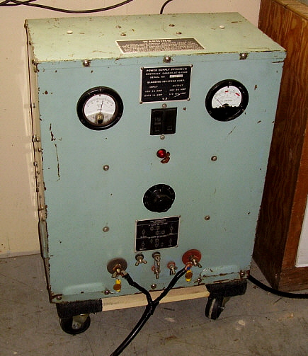
To operate the GRC-19 requires a hefty power supply capable of +28.5vdc at 40 amps - 50 amps is better. Later versions with the solid state +HV dynamotor replacement power supply will operate at about 32 amps. This is "key down" with voice peaks driving the current requirements slightly higher. I use a PP-1104 power supply and have no problems with current requirements. If you have to build a power cable for your GRC-19, be sure to make the cable shielded. The original cable was an eight gauge inner conductor that was the positive and the shield was the negative with the cable length being ten feet. I use a nine foot length of shielded cable that consists of two ten gauge wires and two 14 gauge wires. I tied the two 10 gauge wires together for the positive and tied the two 14 gauge wires along with the shield for the negative. This cable works quite well. If you have to make the cable I would use two eight gauge wires and then use the braided shield removed from old RG-8 coax to make the cable shielded.

Use a Headset for Comfort - 
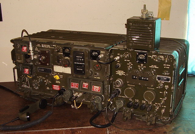
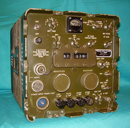
To say that the GRC-19 is a rather noisy transmitter-receiver combination is a real understatement. If you use the LS-166 loudspeaker with the R-392, you will have to have the Audio Gain at least 75% advanced to hear any stations. Forget hearing weak stations. The LS-166 isn't a very good speaker anyway since it was mainly designed to be weather proof. The most comfortable operation is gained by operating the R-392 with a headset with cushions that completely seal the ears. I use the H-301 headset with an extension cable that I replaced the PL-55 plug with a UG-77 plug for interfacing with the R-392. This allows me to reduce the Audio Gain down to 10% advanced or so. Additionally, the noise from the T-195 is greatly attenuated by the cushions on the headset. It really makes operating the GRC-19 about as comfortable as possible.

Initial Tune-up on an Antenna - If you are going to use an Inverted Vee fed with 50Z ohm coax then your antenna load to the T-195 is somewhat dependent on your frequency of operation. If you stay around the AM-MIL frequencies, then the T-195 autotune will easily match to the load since it will be around 50 Z ohms. If you're like me and operate a Tunable Inverted Vee then the initial set-up will require a little pre-testing. My antenna is a 135 ft Inverted Vee antenna fed with 78 ft of ladder line going to a small 275W Johnson Matchbox. Initially, when determining where to set the Matchbox to provide a 50 Z ohm antenna load, I used a Viking Ranger to experiment with what Matchbox settings provided a 1:1 match. Of course, any convenient-to-use transmitter will work. I used a Drake inline W-4 wattmeter and adjusted the Matchbox for minimum reflected power. Once I knew where the Matchbox needed to be set at specific operating frequencies, I logged these settings down and then I was ready to switch over to the T-195. Since I'm setting the antenna/Matchbox combo for 50 Z ohms, the T-195 will auto tune to match that 50 Z ohm load. Before hand, I had the T-195 loading into a 50 ohm dummy load therefore there should be very little auto tuning that needs to occur. You will have some slight autotune action since the antenna/Matchbox combo has some reactance that isn't in the dummy load but the autotune loading should only take a few seconds. If everything is set correctly, you'll have very little reflected power and the T-195 will be running over 100 watts output "key down." You can make very small adjustments to the Matchbox but go slow. Too much change shows up as an error voltage in the discriminators of the T-195 and it begins to autotune to compensate. If you make very small changes (slowly) you should be able to "null" the reflected power. Any antenna/tuner setup should work approximately the same way with the GRC-19, that is, find your antenna tuner settings for a 50 Z ohm load first using a regular ham transmitter and then switch over to the GRC-19.

Microphone Critiques - The "Pork Chop" microphone, the M-29, is a terrible microphone. The M-51 plug-in element (used in the M-29) is awful and even "NOS - in a sealed package" examples won't have much response. I don't know if there were ever any M-29s that worked okay but today it seems like they are all non-responsive and sound terrible. If you find that your Modulation Level on the T-195 is set to about 80% advanced that's usually an indication that it was being used with the M-29. They sound okay with the Mod Level set high but you can't switch to any other kind of mike since all of the other types will require the Mod Level to be around 50% to 60% advanced (with the Clipping set to zero.)

The H-33 handset mike is better sounding but it depends on the mike's condition and to a certain extent on when it was made. Earlier ones (made in the USA) seem to have better quality but that could be just the examples I've seen and heard. Later Euro-built versions sound nasal-like with very restricted audio. It might be because the later H-33 were designed for SSB. At any rate the Euro ones sound pretty bad on AM. By the way, don't listen to the R-392 using the H-33 handset as the quality is pretty bad - a headset is much better since you will eliminate (or greatly reduce) the T-195 blower noise. The best sounding, stock mikes that I've tried so far are Audio Sears and Electrospace Corp. versions of the H-33. When using the H-33, I usually will listen during the net using the H-301 headset but when my turn comes to transmit, I take off the headset and use the H-33 handset. After I finish my transmission I then return to using the headset. Kind of a hassle but the audio using the H-301 headset makes it worth it.

Microphone UPDATE 2016:   Let's face it, the M-29 and the H-33 are not the greatest for microphones. Although the H-33 is better, it's still "rough" sounding at best. I recently heard W1NZR on his GRC-19 and was amazed at his audio quality. Natural sounding with good communications sound. I asked Brown how he achieved such great audio on a T-195. He responded that it was the microphone. He was using one of those Motorola dynamic mikes that have the built-in pre-amp. They were used on a lot of Motorola radio gear in the late-1950s and thru the 1960s (we've all seen them, they're the really ugly ones that Motorola made.) Brown was operating the pre-amp board from the carbon mike bias line and then running the dynamic mike down stream of the carbon mike bias blocking capacitor. Also, Brown had bypassed the Clipper of the T-195. The result was very clean audio that sounded very natural and had a communications bandwidth to it.

Another Microphone Suggestion 2019 - A few years ago I made up a carbon mike for the T-368 transmitter. It uses the same type of UG-77 connector as the T-195. This mike was sort of a "custom job" in that I used a Shure 102-C body, PTT switch and cable but I removed the Shure element. I replaced the old element with a NOS element from a surplus Chi-Comm mike that was a Vietnam-era, Shure look-alike. These mikes used to be available on eBay from various dealers in Chinese military surplus. The mike body is junk but the element is first-class and has plenty of response. The Chi-Comm mike element easily fits into the Shure 102-C body. I used the mike once or twice on the T-368 but went to an amplified TUG-8 stand with D-104 head for that transmitter. The Chi-Comm 102-C just sat around until I was retesting the GRC-19 set up for this season. The HS-33 sounded okay but a little anemic audio-wise. I happened to see the old Chi-Comm 102-C and saw that it had the UG-77 plug installed. I checked the schematics to be sure they were interchangeable and then gave it a try. Lots of response with a full sound to the audio. Now, this mike isn't noise cancelling so I was expecting a lot of blower noise but that wasn't the case. I held the mike about 3" from my mouth and when talking, no blower noise could be heard. Of course, without any speaking, you'll hear the blowers but not when speaking. I got good audio reports from other military radio users on the West Coast MRCG net. These Chi-Comm mike elements might take a little looking to find but they do show up on eBay. They look like a typical Shure handheld mike but painted olive drab.

Another Microphone Suggestion - 2022 - The GRC-19 is located out in the shop. The temperatures in the shop are always cold unless it's the middle of summer. Trying to use the GRC-19 during winter in shop, with the blowers going right in your face, is pretty uncomfortable. So, why sit directly in front of the GRC-19? I rigged up a longer microphone cable which now allows me to sit a few feet to the side of the GRC-19. A lot quieter and a lot better in the winter.

Utilizing the 600Z ohm Line - The T-195 provides a 600Z ohm line that connects directly to the HP filter putting it on the "down stream" side of the carbon mike coupling capacitor. This 600Z input was provided for RELAY operation where the radio operator was receiving a signal on the R-392 on a separate antenna and on a different frequency. With the T-195 switch in the RELAY position, that incoming signal was then routed from the R-392 output via pin A on the T/R interconnect cable connector to the T-195 600 Z ohm line input that is on pin A of the AUDIO connector. Before being routed to the Speech Amplifier section of the Modulator module, the line is routed through a gain control that is marked "LINE LEVEL - DBM" on the front panel. As the radio operator was receiving the signal on the R-392, he would adjust the LINE LEVEL control for proper modulation levels on the T-195. Naturally, the T-195 was operating on its own antenna and on a different frequency than the incoming signal on the R-392. This allowed the radio operator to receive an important signal from say a low power field transmitter that had limited range and then "relay" that signal to the proper receiving station using the higher power available from the T-195 (and probably better antenna set up.)

It's possible to disconnect the R-392 audio output at the T/R interconnect cable by removing the wire connecting to pin A. Then it's possible to connect an amplified mike base (like the TUG-8) with a crystal mike head using a UG-77 connector with the mike connected to pin A rather than pin C. Ground and PTT remain the same connections. Switch to RELAY position on the T-195. Now you will be able to use the LINE LEVEL control to adjust the modulation level for the amplified mike. This allows you to run a crystal or dynamic mike with the T-195 with only a very slight modification to the T/R interconnect cable (and that can be returned to stock at anytime.)

Unfortunately, nearly all crystal and dynamic mike heads will be of the type that are NOT noise cancelling. You might find that the blower noise from the T-195 is over-powering. Close-talking the mike will help but that sort of defeats the audio improvement gained by this change. It's worth a try though because the modification is so simple and so easy to return to stock if desired. See "Another Microphone Suggestion 2019" above regarding no blower noise using a non-restrictive mike.

It should be possible to use a hand-held dynamic mike that has a 500Z ohm load on the 600Z ohm line.

Always Use a 'Scope - When operating "on the air" you should always have a monitor for watching carrier level and modulation level. Any oscilloscope can function as a monitor by connecting a three foot long "pick up" wire to one of the 'scope's vertical amplifier's input. Set the time base (sweep) to whatever gives a good representation of the wave envelope. With this easy set up you can immediately see the modulation level and what the audio waveform looks like. It's also helpful when the T-195 is autotuning to watch the carrier level on the 'scope. As the T-195 "zeros in" on resonance, you'll see the wave envelope increase until the transmitter is at full output. Also, it's helpful to have a digital frequency counter with a "pick up" wire to monitor frequency. The T-195's mechanical digital frequency readout is very accurate but it's nice to have confirmation of the transmitter's frequency.

CW Operation - If you can find someone else interested in military radio CW, the GRC-19 does CW without too many problems. Probably the most difficult problem is installing the UG-77 connector on a cable end so you can "plug in" the key. Another oddity is that you can input the key using one of the spare AUDIO connectors on the R-392. Pin F is the keying line and it is pin F on all of the AUDIO marked connectors including the one on the T-195 and the two on the R-392. Pin F is worked against pin H which is ground on all AUDIO connectors. Since the mike is usually going to be on the T-195 AUDIO connector and the H-301 headset is on one of the AUDIO connectors of the R-392, that leaves just the other R-392 AUDIO connector for the CW key input. The CW key referenced in the manual is the KY-116/U which is a "leg key," that is, the key assembly clamps onto your leg for sending without a table. However, if a table is available the key platform hinges back and the key will set nicely on a table for sending that way too. I've used the leg method and actually it's not bad. Much easier than one would expect. With the leg key you can lean back in your chair, relax and send with your arm in a downward position. Very comfortable.

Operate on the Amateur Military Nets - As with most military transmitters, the T-195/GRC-19 will have to be operated on amateur military radio nets where the participants are familiar with the sound of carbon mikes and the typical restricted audio of later military transmitters. Since the modulator module has filters that limit the frequency response to 300hz to 3500hz and, on top of that, there is a limiter in audio section (and you're probably using a carbon mike,) if you operate on a regular AM net, you're very likely to receive several "critical audio reports" from the "broadcast audio" crowd. The T-195 isn't a broadcast transmitter. It's an electro-mechanically complex, completely autotuning, portable military transmitter that runs a respectable carrier level power output. Stay on the military radio nets and your T-195/GRC-19 will be appreciated for it's unique sound, powerful signal and for the rarity of hearing an operating example "on the air." 

 
Conclusion - The AN/GRC-19 is the type of radio transmitting and receiving equipment that could only have been built during a certain period in military radio history. That would be at a time when vacuum tube technology was at its zenith and at a time when electro-mechanical solutions to automation were all that was available. Nowadays, most modern ham transceivers use auto-tuning antenna couplers with no moving parts. Many remote antenna couplers also provide impedance matching without moving parts - all completely electronic solutions driven by microprocessors. The AN/GRC-19 is a marvel from another time with complex tube circuitry driving servo motors to provide that automatic tuning solution. Additionally, to build a T-195 or R-392 would probably be impossible today. No company would touch such a contract since no profit could be realized and the complexity would be next to impossible to economically duplicate. So, appreciate your GRC-19 - it could only have been built during the Korean War and Cold War Eras, a time when everything came together for vacuum tubes, complex electro-mechanical solutions and heavy, expensive gear. The military wanted it, our country provided it and the best manufacturers in the world built it. And now,...we get to use it (without getting shot at.) References

1. TM 11-806 - U.S. Army manual for the T-195 Transmitter

2. R-392 manual

3. TM-11-5820-295-10  U.S. Army Operator's Manual AN.GRC-19

4. Electric Radio - Issues #113, #114 & #115 contain an article by Collins Engineer Fred Johnson on the mechanical design of the T-195. ER issue #104 contains an article by Dennis DuVall on the electronic design of the T-195.

5. Online sources - There are a few comments found here and there on various websites. Scant details on most postings.

Henry Rogers, Radio Boulevard, Western Historic Radio Museum © September 2013


Return to Home Index


Radio Boulevard
Western Historic Radio Museum

 Vintage Radio Communication Equipment Rebuilding & Restoration Articles,

 Vintage Radio History and WHRM Radio Photo Galleries

1909 - 1969

- 60 years of Radio Technology -


This website created and maintained by: Henry Rogers - Radio Boulevard, Western Historic Radio Museum © 1997/2023