Radio Boulevard
Western Historic Radio Museum
 

THE COLIN B. KENNEDY COMPANY

"RADIO APPARATUS OF QUALITY"

1921-1922 Experimenter's & Commercial Receivers
Type 110  "Universal Receiver"
     Type 220  "Intermediate Wave Receiver"
Type 281 "Short Wave Receiver"

   1921-1922 Two-Stage Amplifiers
Type 525 & Type 521

History, Circuits, Documentation, Restoration
 Performance, Using Kennedy Equipment Today
 

by: Henry Rogers WA7YBS/WHRM


Kennedy Universal used "portable" circa 1923. Also note the Magnavox amplifier on the running board and Magnavox R-3 horn speaker on the Kennedy along with the earphone sets hanging from the car's top and the loop antenna on the hood. A real first-class portable receiving station.  Photo from the Henry Ford Museum and Science&Invention Magazine


"RADIO APPARATUS OF QUALITY"

The Colin B. Kennedy high-end regenerative receivers of the early 1920s were the favorites of many experimenters, radio enthusiasts and some commercial users. One could find these quality-built receivers in AM Broadcast stations where they were used to monitor the 500kc emergency frequency as required by early radio broadcasting regulations. They were also found in laboratories that required a precision, dependable receiver for their research. Then, finally, there were the radio enthusiasts, from wealthy hams to rich radio fans, that had to own and use only the best, well-made equipment. Certainly, top-notch performance was garnered from using the Kennedy receivers back in the 1920s. But what about today? Many collectors find the Kennedy receiver's operation a mystery and have difficulty tuning in anything other than local AM Broadcast signals. These incredible receivers are still great performers, even though they do have their "quirks" that often lead users to believe the sets are impossible to operate today. A properly set-up Kennedy can receive just about anything that's "on the air." Here's an in-depth look at some of the best-built radio equipment available in the early 1920s. - H. Rogers 2009
Colin B. Kennedy - Colin B. Kennedy was a Canadian, born in Ontario in 1885. He worked as a telegrapher as a teenager and eventually worked his way west to Vancouver Island, where he ran two Canadian government wireless stations. He later worked for Federal Telegraph Company for a while and was transferred by that company to Palo Alto, California. It was in California that the idea of running his own business developed. By 1920, Kennedy was building equipment for experimenters, which were "hams" or "enthusiasts." Kennedy also sold other manufacturer's components and operated 6XAC in Los Altos, California (1921 - though it was located at the home of his production manager, Emil Portal.) Selling to experimenters kept the few Kennedy employees working but when broadcasting started to become popular, everyone wanted radios so the Kennedy employee ranks grew rapidly as orders piled in. This increase in business caught the attention of Wagner Electric, who had an office in the same building as Kennedy's office in San Francisco (even though Wagner Electric was a St. Louis, Missouri company.) Wagner had wanted to "get into" the radio business quick, so in June 1922, the bought up the Kennedy Company and moved the operation to St. Louis. The same line was continued for a while but soon Kennedy, more and more, was becoming a broadcast receiver company making expensive, elegant radios that would fit into the home decor rather than the experimenter gear they had started out with. By 1926, the radio boom was over and Kennedy-Wagner was bankrupt. Colin Kennedy started a couple of business attempts afterward but it wasn't until he got involved with Studebaker, in 1928, that he actually built some more radios. Most of these radios were pre-built chassis that were installed into pre-manufactured cabinets and then sold. This Kennedy company also eventually failed in 1933. Colin Kennedy joined the Signal Corps as a civilian employee, in Chicago, in February 1942 but died four months later at the age of 57. The 1921-22 Experimenter's & Commercial Line - Kennedy's line of high-quality radio receivers were popular with enthusiasts, experimenter's, commercial users and radio amateurs. Kennedy also built some high-quality broadcast receivers that were more for the typical "radio fan" with designs that would fit into the home living room decor. These receivers had slant-face panels in dark walnut cabinets. Some had gold dials and panel meters. Some receivers were fitted into console cabinets. The Kennedy V, VI, XV and XXX models were probably the most popular of these types of radio receivers. This article details the Experimenter's and Commercial Line of receivers, the Type 110 Universal, the Type 220 Intermediate Wave and the Type 281 Short Wave along with the matching audio amplifiers, the Type 525 and the Type 521.

Kennedy's Method of Construction - Kennedy's early receivers, made in San Francisco, were all hand-made using machine tools. This method resulted in minor variations in the appearance or dimensions of many of the receiver parts since the machines were operated by human hands. Comparing one early Kennedy receiver to another will certainly show minor differences between the two sets. As an example, the early Kennedy knobs were made from .5" thick sheet hard rubber by drilling a pattern of small holes in a circular layout and then cutting out the circle while bisecting the smaller holes. The resulting piece was a fluted knob that was then beveled and polished. Because of the "hand work" involved to make the knobs they all have slight variations when compared to other knobs. These variations and the methods of manufacture can be seen in all of the hand-made Kennedy parts. To say that "no two Kennedy receivers are alike" is not much of an exaggeration,...depending on how closely you look at the details.

Differences in San Francisco and St. Louis Manufacture - After the move, in June,1922, Kennedy receivers made in St. Louis changed rather quickly in subtle details. This was probably due to different tools for manufacture, possibly different personnel, different suppliers of materials and the expected evolution of radio design. In San Francisco, the receivers used all metal binding posts which was due to the handmade nature of all of the parts. In St. Louis, bakelite capped binding post were used, probably supplied by an outside source. Tube sockets used in early receivers were supplied by General Radio or Paragon but later receivers made in St. Louis will have Kennedy marked sockets. The knobs become molded pieces in St. Louis. In San Francisco, the  receivers had early circuitry, e.g. a plate potentiometer adjustment control on the large sets and extra Antenna Tuning range on the shortwave receiver. These controls were simplified or eliminated in the St. Louis manufacturing. As receiver technology evolved, so did the Kennedy receivers. It is common to see many differences when comparing earlier San Francisco receivers with later St. Louis versions.  


Type 110  Universal Receiver

The Kennedy Type 110 Universal Receiver  was introduced in July, 1921. Its heritage comes from Kennedy's early receivers, the Type 100 and the even earlier LWR-20. Its incredible tuning range starts at 150 meters and ran all the way to 25,000 meters - that's from 2.0mc down to 12 kc. "Universal" meant that it would tune in anybody that was on the air in 1921. Though the advertised shortest wavelength was 175 meters, or about 1.7mc, I have found that most Universals will tune up to 2.0mc, or 150 meters (in fact, this applies to the Type 220 and Type 281 as well.) The Type 110 is a three-circuit tuner utilizing a regenerative detector designed originally for the detector tubes available in 1921. Later manuals and advertising specify the UV-200 "soft detector" tube. The UV-200 was also known as a "gas" detector tube since it had some argon inside the envelope. These detector tubes require a little time to come up to full sensitivity, usually about 5 minutes warm-up is sufficient.

The Primary circuit uses a tapped inductance that can be set to nine different positions each of which can be tuned by the Primary condenser, either connected in series or parallel. The Primary circuit is essentially an Antenna Tuner and, with proper adjustment, maximum signal levels are inductively coupled to the Secondary circuit using a variable Coupling coil. The Secondary circuit uses a tapped inductance that can be set to seven different positions and tuned with the Secondary condenser providing seven tuning ranges. The Secondary circuit tunes the incoming signal from the Coupling coil which is located inside the Primary Inductance which is then routed to the detector input. The Coupling coil rotates 180º which varies its position relative to the Primary Inductance's axis and therefore couples more or less signal energy to the Secondary circuit.

The Regeneration is adjusted with a variometer in the detector plate circuit. With variometer controlled regeneration it's important that the plate circuit is routed through the rotor first and then through the stator coils. Although the detector tube inter-electrode capacitance provides a grid to plate resonant feedback path for regeneration and there might be some stray EM coupling between the variometer and the secondary circuit, better feedback can be achieved using tickler coils. Below the variometer is a set of tickler coils that are connected in series from the secondary circuit coils to the detector grid. The variometer is in the plate circuit and it's important that it's correctly wired into the circuit to reverse the phase so that the variometer's EM field can easily couple with the grid tickler coil. Adjusting the variometer rotor changes the total L in the plate circuit to resonate with the grid circuit but it's the increasing EM field of the variometer as it approaches resonance and, since the variometer and the ticker are mutually in phase, as the EM field-coupling increases it creates a "positive feedback" at the grid that increases gain or sensitivity. Of course, too much coupling (close to resonant tuned) will cause the detector to break into oscillation and become an autodyne detector capable of demodulating CW signals. Since the Primary circuit can maintain a fairly constant load on the detector grid circuit (Secondary circuit,) the Regeneration control settings are always within the range of the variometer and thus control the amount of feedback and the detector sensitivity. The variometer-tickler uses multiple tickler coils that are switched with the secondary range switch and are mounted directly below the variometer to assure enough feedback is available in all of the tuning ranges. A variable condenser is used as the grid-leak condenser so that optimum performance can be achieved on all wavelengths.

The panel mounted DC Voltmeter indicates the voltage at the filament pins of the UV-200 detector tube. It is mentioned in early Universal advertising that the filament meter measures "filament current," implying that a DC Ammeter was used. In 1921, many receivers were still using Moorhead ER tubes which specified 400mA of filament current for proper operation.


photo above: The Kennedy Universal Receiver Type 110, St. Louis version, SN: 5403  ca: 1922-23. This example is a beautiful condition, all original, functional receiver.
 

This Kennedy Type 110 Universal receiver SN:5403 was almost destroyed in a 1984 house fire. Fred Winkler, who was an old collector friend of mine, had only seconds to make a decision before escaping his burning house - which radio to save. He grabbed this Kennedy under his arm and rushed out of the burning house. Unfortunately, the rest of Fred's radio collection was destroyed along with most of the house. I purchased this Universal from him in 1994.

Back around 1978, Fred had traded an old AC-operated radio that functioned for the Kennedy Universal. Dave Woods, who owned and operated an antique-junk store in Moundhouse, Nevada, was the owner of the Kennedy at the time of the trade. It shows that to non-collectors a functioning radio is "all important" and Fred knew how to take advantage of that fact.


photo above: The impressive interior of the Kennedy Type 110 Universal Receiver, St. Louis version. Note that the bank wound inductances are yellow-orange color from the amber shellac used to seal the coils. The coils top-right and top-center are the primary inductances. The coils bottom-center are secondary inductances along with the tickler coils below the variometer (top-left.) In front of the detector tube is the variable grid-leak condenser.

The quality of construction and components used on the 110 is impressive. The bank-wound* inductances are necessary for wavelengths longer than 1000 meters and this method of coil winding reduces distributed capacitance and prevents oscillation at unwanted frequencies. Cotton covered Litzendraht wire is used for the coils which were given a coat of amber shellac to protect and secure the windings. Kennedy advertising implied that the coils were "moisture-proof" because of this coating. The variometer uses a molded bakelite housing and rotor which results in a precision instrument for controlling regeneration. Due to the very long wavelengths that the 110 can tune to, a dual secondary condenser is used. On band 7, the additional variable condenser is switched into the circuit to allow the 110 the ability to tune down to 12kc, or 25,000 meters. Additionally, the two largest bank-wound inductances are connected in series on band 7 to further allow tuning to this very low frequency. The Inductance switches are point contact types that are mounted behind the panel with pointer knobs and numerals engraved on the front panel to indicate which inductance tap was switched in.

Early 110 receivers will have a Plate Potentiometer adjustment which is a fairly high value variable resistor connected across the A battery terminals with the receiver B- connected to the arm of the variable resistor. This allowed electrically adding the A battery voltage to the detector plate battery voltage. With an 18vdc detector plate battery, the operator could adjust the Plate Potentiometer to any detector plate voltage from 18 to 24vdc. This control was eliminated from the later 110 production for several reasons. First, if left connected up it was a drain on the A battery. Second, the UV-200 production was more predictable in its filament to plate voltage ratio and the operator could accomplish more or less the same effect by raising or lowering the filament voltage.

*Bank-wound coils consist of an initial wind but at the end of the initial layer the coil wire is returned back to the first wrap "start" minus one turn. At this point another layer is wound on top of the first layer but ended one turn before the end of the initial layer at which point the coil wire is again returned to the "start-end" minus one turn and another layer is started. This process continues until the desired inductance is achieved. 

The front panel is made of .250" thick Formica with a high polish finish. The engraved nomenclature is usually filled with white paint, however some San Francisco versions have gold filled engraving. The dial scales are matte-silver plated. Tarnish and wear are common since the finish on these dials is very delicate. The cabinet is made of solid walnut with a shellac finish. All of the hardware is nickel plated.

The Universal required a six volt storage battery for the A supply. Today, any well filtered 6vdc power supply that is capable of a few amps is sufficient. The Detector B+ is usually around +22.5vdc. The pure tungsten filament UV-200 tube requires 5vdc at 1A, although most good emission tubes will run with fine sensitivity at about 4.5vdc.Unfortunately, pure tungsten has a finite life and when tungsten filament tubes have weak emission there is nothing that will bring the filament emission back and the tube must be replaced. 

When using just the 110 receiver with no audio amplifier, a good set of earphones is necessary. Baldwin 'phones with their direct-driven mica diaphragms have the best sensitivity, sometimes equivalent to a single stage of audio amplification, when compared to standard ferrous-diaphragm 'phones. If the Type 525 Two-Stage Audio Amplifier is going to be used, the A supply will have to be capable of supplying at least four amps (one amp "headroom.") The Universal's Telephones output is strapped to the Type 525 Input and the 'phones connected to the Type 525 Output. Detector, 1 Audio Amplifier or 2 Audio Amplifiers can be selected by inserting the corded telephone plug into the appropriate phone jack. The Type 525 filament controls will determine the amplifier gain. Horn Speakers can be driven by the Type 525 but only for Broadcast reception, the other signals generally being too weak to be heard in the loud speaker.


photo above: The San Francisco version of the Type 110 Universal Receiver ,  SN: 951 ca. 1921.
 

QST Ad April 1925 - The last of the 110s were offered for sale in April, 1925. That the advertisement was in QST seems to imply that the general radio buying public probably wouldn't have been interested in a large, difficult to use, regenerative receiver in 1925 but, maybe the hams might be interested. For the QST sale price of $95, the 110 was a bargain for anyone who wanted to own one of the best built radio receivers of the time. The original selling price in 1922 was a staggering $250.

San Francisco Type 110 Universal Receiver - I've owned the Kennedy Type 110 Universal SN: 951 (shown above) for over 30 years. I purchased it from Paul Giganti. It was the victim of several modifications, as many Type 110s were, so I performed a complete, authentic restoration on the receiver to return it to original condition and to be fully functional. I won first place in  Radio Age's Radio Reception Contest in the late-1980s using this SF Type 110 with its matching SF Type 525 Audio Amp. I entered in the category "Regenerative Receivers."  I only tuned in 26 AM BC stations because I had to wait for each BC station to ID themselves which used up most of the time allotted for the contest. I don't know how I won the contest-category with only 26 stations logged - no competition, I guess.
 

Type 220  Intermediate Wave Receiver

The Kennedy Intermediate Wave Receiver was introduced in 1921. Its appearance is similar to the earlier SWR-6 but that receiver tuned the Short Waves. It is also similar its immediate predecessor, the Type 200 (though the Type 200s tuning range is also usually specified as Short Wave.) The Type 220 was built to the same high quality as the Universal Receiver but the tuning range was from 150 meters up to 3000 meters, or about 2000kc down to 100kc. This is a good portion of the Medium Wave and Low Frequency part of the spectrum, so the Type 220 was designated as an Intermediate Wave Receiver. The Type 220 circuitry is essentially the same as the Universal with adjustments made to the coil and condenser size due to the receiver's reduced tuning range. One readily visible difference is the mounting of the inductance switches in which the contacts and arms are fully exposed with front panel mountings. The Primary Inductance switch has nine positions for tuning the antenna and a Series-Parallel switch was included to select whether the Primary Condenser was connected as a series LC or a parallel LC. The Secondary Inductance switch has four positions that select tuning ranges with the highest frequency range selected by rotating the knob fully CCW. The ranges approximately tune 2000kc to 800kc for Band one, the highest frequency position. Band two covers 1000kc to 500kc, band three covers 600kc to 300kc and band four covers 300kc down to 100kc.

The Type 220 Coupling and Regeneration controls use matte silver-plated dials and the Filament control uses a knob with no scale. There was no "fine tuning" adjustment knob on the Secondary condenser on the early models, however, later versions of the Type 220 will have this feature. Sometimes an extra filament potentiometer will have been installed to allow the use of a UV-200A tube with .25A filament. This modification was usually a dealer addition if the work was of professional quality. A filament voltmeter was not used in the Type 220.

The Type 220 went through the same evolution as the Universal so early versions, made in San Francisco, will have nickel-plated binding posts and a Plate Potentiometer control while the later St. Louis versions have bakelite capped binding posts and no Plate adjustment. Most Type 220 coils are coated in clear shellac giving the coils a white appearance while most Type 110 receiver coils were coated with amber shellac. While most components aren't interchangeable, the same quality and style of manufacture is used in the Type 220 as with the other 1921-22 Kennedy equipment.


photo above: The Kennedy Type 220  Intermediate Wave Receiver , early St. Louis version, SN:5118.

 A dump rescue, this receiver was restored first in 1986 and then again in 2016.

The wiring layout was also changed during production from early to late versions. This is even true specifically for early St. Louis receivers and late St. Louis receivers. Some wiring layout was changed due to component relocation or physical component changes.

It doesn't help restorers of the Type 220 that the schematic in Rider's Perpetual Trouble Shooter's Manual is fraught with errors including the incorrect A- to B- connection (which should be A+ to B-.) If wired as shown in Rider's then the Type 220 couldn't be used with the Type 525 Amplifier. (More details on schematic errors for all Kennedy receivers further down this page.)

Where this Type 220 Came From - It is interesting to note that the Type 220 shown in the photos (sn 5118) was 10 seconds from being thrown into the Carson City, Nevada dump back in 1986. It had been in a chicken coop that was being "cleaned out" and was considered merely more junk to be discarded. My old radio collector friend, Fred Winkler, happened to be at the dump at the same time and saw the Type 220 about to be hurled onto the heap.

"Hey! Wait a minute," Fred yelled.  This stopped the toss at mid-point and, after a short conversation with the coop-cleaner, the Type 220 was in Fred's possession.

Fred's phone call to me started out, "You know anybody that has a Kennedy variometer?"

"Yeah, me," was my reply.

"Well, come over. I have a Kennedy 220 for you that's missing the variometer."

I traded Fred a National RBL-2 Longwave receiver for the Kennedy. The Type 220 needed a bit more than the variometer though. The cabinet was in pieces and needed to be reassembled and glued. The secondary tickler coil assembly that mounts under the variometer had to be replicated. The filament pot needed to be rewound with Ni-Chrome wire. I had the correct dial for the variometer (Regeneration) but I didn't have the filament control knob. Luckily, I found one at a swap meet a week or two later. I had to make several of the bakelite caps for the binding posts. Also, I fabricated the thumb screws that hold the lid down. All of the hardware was re-nickel plated so that all of the pieces matched when reassembled. It was lucky that I already had the correct Kennedy variometer in one of my parts boxes. That piece would have been impossible to replicate.

The Type 220 worked okay after its resurrection. Performance is similar to the Kennedy Universal in most ways. Tuning is limited to four bands. With its smaller dimensions, it would have seemed that the 220 would have been a popular receiver but it is not seen as often as the Universal Receiver. Selling price was $125, half the cost of a Universal, but it didn't seem to make a difference. In the 1921-1923 time period, most radio purchases were made by radio enthusiasts and they wanted the biggest and the most elaborate radio gear, which accounts for the somewhat limited popularity of the Type 220. 

In 2011, I was able to obtain a "parts set" Kennedy Type 220. This "parts set" receiver was used for a "re-do" of this 1986 restoration. The process is detailed a section further down this page. Also included is a performance write-up. 

The photos above and to the left are of the Type 220 after its 2016 "re-do."

Movie Alert - Be sure to keep an eye out for the 1930 movie, "The Green Goddess," which features several good shots of a Kennedy 220/525 combo in the wireless station that figures in the movie's plot. I saw the movie on Turner Classic Movies Channel.


Type 281   Short Wave Receiver

The Type 281 Short Wave Receiver was intended for the experimenter, radio fan or ham operator. It tunes from 150 meters to about 650 meters, so it would receive most of the popular transmissions in the early twenties. The Type 281 wasn't popular as a ham receiver, probably due to its somewhat high selling price of $90 when compared to similar Grebes or Paragons. The same Kennedy level of construction quality is used in the Short Wave Receiver but since it only tunes in the higher frequencies, the components are small and the receiver interior appears rather sparsely populated since there is an absence of large inductors or huge condensers. In keeping with the style of receiver that the hams would appreciate, black dials with silver nomenclature were used on the majority of  Type 281 receivers. There are some indications that some of the early San Francisco versions used matte silver plated dials but these are rare sets that are seldom seen. The earlier San Francisco version Type 281 also included a more elaborate Antenna Tuner with two sets of point contacts and only a single antenna binding post. The St. Louis version replaced the double tuned antenna tuner with a single set of switch contacts and added two antenna binding posts, "L" and "S", to increase the antenna tuning range depending on the type of antenna used. The "L-S" switch is for changing the tuning range from longer waves to shorter waves. A vernier tuner was added to the Short Wave Receiver that is actually a real vernier condenser rather than a mechanical "slow motion" control, as in the Universal Receiver.


photo above: The Type 281 Short Wave Receiver,  St. Louis version

I traded some Moorhead ER tubes and other early hand-made tubes to Will Jensby for this Kennedy Shortwave and the matching Type 521 amplifier. I've had this set for about 20 years.


photo above: The sparse interior of the Short Wave Receiver, St. Louis version

In order to fit the variometer into the small cabinet of the Type 281, it is mounted "sideways" or 90º difference from the standard mounting used in the Universal or the Intermediate receivers. Another departure was the cabinet itself, perhaps for cost or maybe for appeal to the hams, the cabinet is made of mahogany and stained dark reddish-brown.

The Type 281 may not have been too popular with the hams but it is a great little receiver and performs quite well. Since it doesn't have to tune the long wavelengths, it is a very simple receiver with very few components. Also, since it tunes the shorter wavelengths, it seems to perform better because the majority of signals (AM BC) in that part of the spectrum are much stronger than the typical longwave signals. The Type 281 will receive ham signals on 160 meters and the hams running AM stations sound very good. When listening for CW signals, the detector must be oscillating and that ends up with a lot of hand-capacity problems making tuning difficult. SSB signals encounter the same difficulty. At the time the Type 281 was new, most hams were on damped-wave spark using rotary gaps which would have been received somewhat like a modulated-CW (MCW) signal, that is not requiring the detector to be oscillating.


Type 525 & Type 521  Two-Stage Amplifiers

Kennedy offered two popular Two-Stage (Audio) Amplifiers that were intended for use with their regenerative receivers. The larger Type 525 was intended for use with either the Universal or the Intermediate receivers sold for $85. The smaller Type 521 was intended for use with the Short Wave Receiver sold for $55. Both amplifiers were two-stage, transformer coupled audio amplifiers that use "hard amplifier" tubes with pure tungsten filaments, the UV-201. These tubes require 5vdc at 1A to light the filament. When operating with a receiver, the total current requirement for this setup is 3A (or 15 watts.) These amplifiers can be operated with 201A tubes as long as the A supply has some adjustability to compensate for the limited resistance of the amplifier's filament controls. The amplification selection is accomplished by inserting the corded telephone plug into the appropriate phone jack for "D" (detector only,) "1" (det+1AF) or "2" (det+1AF+2AF.) The Telephone output on the receiver is "strapped" to the amplifier "INPUT" and the amplifier "OUTPUT" is used for either earphones or a horn speaker. Plate voltage on the tubes is normally around +60 to +90vdc. Although the manuals show +60vdc for the Plate voltage, I have found that these amplifiers work much better with +90vdc on the Plates.

The amplifiers follow the same basic evolution as the receivers. Note that the San Francisco version Type 525 has the phone jacks located at the bottom of the panel while the later St. Louis version has the phone jacks in the center of the panel. 

Operating any of the Kennedy receivers without an audio amplifier is a challenge when searching for DX signals. You need to use really good 'phones, like Baldwin Type C, to have enough audio on the really weak signals. A Two-Stage Audio Amplifier is a tremendous help in hearing the really weak ones.

As for documentation, neither of the Kennedy Two-Stage Audio Amplifier schematics are in either Rider's PTSM or in Gernsback's ORSM.


Type 525 San Francisco version SN 644


Type 525 San Francisco version - interior


photo above: Type 525 Saint Louis version - the switch between the filament dials is not original. It switches B+ on or off. 

photo above: Type 521 San Francisco version with bakelite capped binding posts


photo above: Type 521 interior


Miscellaneous Information on Kennedy Receivers & Amplifiers

Variations Commonly Seen in Kennedy Receivers & Amplifiers - Here are some of different variations seen on the Kennedy equipment. Remember, almost all early receivers are slightly different from receiver to receiver and have subtle differences due to the handmade nature of manufacturing. This list is for the major changes encountered in the receivers and amplifiers. The minor differences are endless.

1. Nickel-plated binding posts are used on most of the San Francisco production
2. Plate Potentiometer circuit is included in early San Francisco production
3. General Radio and Paragon tube sockets used in early San Francisco production
4. Knobs are hand-made in early San Francisco production
5. Secondary coil terminals located on back of coil assembly
6. Position of phone jacks on 525 amplifier lower part of panel on San Francisco production
7. Bakelite capped binding posts used in most of St. Louis production
8.. Knobs are molded pieces in St. Louis production
9. Tube socket is a Kennedy marked piece in St. Louis production
10. Plate Potentiometer eliminated in St. Louis production
11. Series-Parallel switch moved from center-left panel to near primary condenser in St. Louis production on the Universal Receiver
12. Size of tube viewing ports reduced in St. Louis production
13. Serial numbers eliminated from the front panels in late St. Louis production - serial numbers are then on metal tags inside cabinets
14. Additional pot sometimes added to filament circuit to allow easy use of .25A tubes - I have seen this on several different Kennedy receivers. The workmanship is usually very good leading one to believe the work could be factory. Dealer installation on earlier receivers also a possibility.
15. Position of phone jacks on 525 amplifier center of panel on St. Louis production
16. Late-St. Louis 220 will have a metal support bracket for primary coil form that mounts to the cabinet front-top piece
17. Late-St. Louis 220 wiring to terminals is soldered directly to the back of the terminals. Earlier 220 used solder lugs under terminal mounting nut.
18. Late-St. Louis 220 tube socket mount is larger than the early-St. Louis 220 tube socket mount.
19. Grid Leak capacitor mounted behind tube socket on Late-St. Louis 220 versions. Grid Leak capacitor mounted on underside of tube socket mount on early-St. Louis 220 versions

The RF Amplifier for the Kennedy Universal  -  These are very rare items. I have only seen one and that was several years ago in Paul Giganti's collection. These RF amplifiers were not made by Kennedy, although they match the 110 in size and general appearance. The RF Amplifier was made by a small company located in Oakland, California. I believe the circuit used a single 201A tube acting as the RF amplifier. The size is similar to the Kennedy 525 AF Amplifier and the cabinet shape is also similar. I don't know what the type of wood used was. The panel has two fairly large black bakelite dials and the engraving is white filled. The entire appearance, though not perfectly matching, is a close match to the Kennedy 110. The example that Paul Giganti had included the original cardboard box for the unit.
 

Schematic Errors Abound

Documentation - When the Kennedy receivers were originally sold in the early-twenties a user's manual came with each set. Besides the operating instructions the manual included a schematic, sometimes called a "wiring diagram" at that time. These schematics are probably the best source for what is correct for each receiver. I have an original Universal Type 110 manual and the schematic included is correct for the St. Louis 1922 versions of the Type 110. I've also examined an original manual for the St. Louis Kennedy Type 220 and its schematic is correct for the SL version Type 220.

By the late-twenties, the "Radio Service Industry" was growing fast and many of the technicians doing repair work needed schematics. The earliest "Service Manual" that was a compilation of schematics from many different manufacturers was probably "The Official Radio Service Manual" published by Hugo Gernsback in 1930. Gernsback was the publisher of Radio News magazine throughout the 1920s and many of the performance reviews of new radios often included schematics. These "Radio News" schematics were the probable source for documentation on radio models that were "out of production" and from companies that no longer existed. Kennedy is represented with two pages of schematics in The Official Radio Service Manual. The Type 110, Type 220 and Type 281 schematics are shown (along with a few other Kennedy broadcast receivers.) All three schematics have errors from minor to serious. It's not surprising since the receivers had been out of production for several years and the Kennedy Company was just about out of business by 1930. Enter John Rider with his "Perpetual Trouble Shooter's Manual" published in 1931. Rider's manual was another compilation of schematics from many manufacturers. The first edition went on to become Volume One of a series of 23 "Radio Service Manuals" that were published each year with new radio schematics. Rider's first edition (or Volume One) tried to cover the same "out of production" radios that Gernsback's manual did. In fact, the Kennedy schematics in Rider's are exactly the same schematics that were in Gernsback's manual - errors and all. It seems likely that Rider's source, at least for the Kennedy receivers, was Gernsback's Official Radio Service Manual.

Beware of Rider's Kennedy
Schematics - Unfortunately, the best known and easiest to find Kennedy receiver schematics are from the first volume of Rider's Perpetual Trouble Shooter's Manual. However, the Rider's schematics are fraught with errors and really can't be relied upon for complete accuracy. Any detailed examination will reveal numerous errors. For example, note on the Universal schematic, the DC Voltmeter is shown connected across the A+ and A- terminals thus measuring battery voltage only. In the Intermediate Wave schematic, the A- is referenced to B- which would prevent using the receiver with the Kennedy audio amplifiers (using tapped B battery with common B- terminal.) The original Kennedy manuals included different schematics than those found in Riders' PTSM. The Kennedy Type 110 SL and the Type 220 SL schematics seem to be correct and there's a link below for reference. The Audio Amplifiers are not included in Riders or in Gernsback and weren't included in the receiver manuals. More details follow,...

Correct Schematic for the Type 110 Universal Receiver - The commonly found Type 110 schematic that was published in Volume One of Rider's Perpetual Trouble Shooter's Manual (PTSM) has several errors. This was probably due to the fact that the first Riders' book was published in 1931, many years after the Kennedy 110 production had ceased and actually after the Kennedy company had ended operations. John Rider undoubtedly used Gernsback schematics since both schematics are identical thus having the same errors. Fortunately, I do have the original manual for the Universal Receiver Type 110 SN 5403 (dated Dec. 12, 1922) which contains the 1922 Kennedy-version schematic. This schematic appears to be correct for St. Louis Type 110 receivers.

Click here for a scan of this schematic:  KENNEDY ST. LOUIS TYPE 110 SCHEMATIC 
Correct Schematic for the Type 220 Intermediate Wave - The schematic for the Type 220 that is in Rider's Volume One is also fraught with errors. The most serious error is referencing the A- to B- which, if it was "factory wired" that way, would prevent using the Type 525 amplifier since it is referenced A+ to B- (as are all Kennedy apparatus.) The actual schematic error is opposite polarities are shown for the A battery connections. As stated before, Rider's source for the Kennedy Type 220 was the Gernsback schematic - errors and all. I don't have an original manual for the Type 220 but, luckily I do have a decent photograph (it's readable) of the schematic within the Type 220 manual (dated Nov. 28, 1922) and it is correct for the St. Louis version. I haven't seen an original manual for the 281 but I would bet that its schematic is also correct.

Click here for a photograph of this schematic:   KENNEDY ST. LOUIS TYPE 220 SCHEMATIC


Restoring and Operating Kennedy Receivers Today

Front Panel Care - Even though the formica panels look indestructible, they are somewhat delicate. Don't use any kind of abrasive polishing compound on the panel. If the panel looks "spotted" or "dull," and you polish it with abrasive compound, the "spotting" will get worse. This is because the actual high-polish skin of the formica is very thin and with age, exposure to excessive moisture or excessive polishing, the material under the skin begins to show through. More polishing only thins the skin so that more "spotting" develops. About the only thing that can be done is to apply Carnauba wax since it is non-abrasive. If the front panel is in excellent condition with no spotting or dull spots, don't do anything to it other than to wipe it carefully with a clean soft cotton cloth to remove dust. Cabinet Restoration - The original finish was shellac, so it is somewhat delicate compared to modern finishes but at the time the Kennedy receivers were new, shellac was a common finish found on many types of furniture. Shellac will do odd things though and an "alligator" look, checking or wrinkling comes from constant exposure to widely varying temperatures found in poor storage conditions. If the finish is really bad, "Amalgamator" (available from Mohawk) will usually correct the problem. Amalgamator is a mixture of denatured alcohol, lacquer thinner and a few other chemicals. It is brushed on the finish where it then dissolves it and then, as it dries, allows the finish to set up again, usually looking better than it did before the application. If a total refinish is necessary, then shellac should be used. Most shellac used at that time was Amber Shellac which has an orange-brown color to it.
Matte Silver Dials - Handle these dials with care as the matte silver plate is extremely delicate. Don't use any abrasives, don't aggressively clean or use any scrubbing action, don't use Windex. Just about everything that we normally use for cleaning seems to degrade the finish on these dials. I have soaked them in warm soapy water (dish soap) for an hour with no adverse reactions. I gently dry the dials with a cotton cloth - no paper towels. This is about as aggressive as I would get cleaning the matte silver plating. At one time, Roland Matson refinished these dials in the correct manner but Roland is now long gone. Available on the web are several rub-on silver plating concoctions but whether they end up looking correct is unknown. Many of the silver plating solutions use cyanide in the mixture, so I think it's probably best to just leave the dials original. Type 281 Dial Restoration - These dials seem to take a beating too. I have tried thinly painting the dials and then applying a silver paint fill but the results were less than satisfactory. The black has to be very, very thin. What does work is to use black "patina" - a chemical dye that is usually available at "Stained Glass" shops. They use it for dying the solder over the copper strips used in making leaded glass items. The "patina" will dye the dial metal (brass) black. Then the silver fill can be added and it will look correct. After the paint dries, the dial can be given a coat of clear lacquer. The original dial finish was somewhat glossy.
Synchronizing the Variometer on Kennedy Receivers - Proper orientation of the variometer rotor assures that the phase relationship will be correct and that the total inductance will change in the correct direction which assures that the proper sign of the EM field is correct for proper regeneration in combination with the tickler coil set. There are four quadrants to the inductance and sign changes for the rotor position and if the variometer rotor is not synchronized, the receiver detector may not oscillate or may oscillate uncontrollably. First, rotate the Regeneration control to "0" and look at the variometer rotor. You should see right through the rotor as it should be fully inline with the frame. Now look at the right side (looking from the front of the receiver) of the inside of the rotor and you should see the splice that connects the two rotor coils. If you don't see the splice on the right side then the variometer is not synchronized. To resynchronize, loosen the two set screws on the rear rotor shaft 0-180º stop. Then set the rotor so that the splice is on the right and the rotor dial (Regeneration) is at "0" and then set the stop and tighten the set screws. Check the rotation to make sure the rotor isn't physically contacting the stator coils and that the position of the stop is correct. Be sure to check the two flexible wires that exit through the hollow rotor shaft. These should not tangle or twist excessively during rotation. It is also important that the variometer is connected to the circuit correctly for proper operation of the Regeneration control. When looking at the variometer from the rear, the Plate connection should be to the terminal on the lower right of the variometer frame. The Telephone condenser/output (and to B+ through the 'phones) connection should be to the terminal on the lower left of the variometer frame. In the Shortwave Receiver Type 281, the entire variometer is mounted 90º difference from the Type 110 and Type 220. The same connections and same references apply, just take into account the difference in the variometer mounting. If after you have synchronized the variometer as described above and you have made sure that the connections of the Plate and Output are correct and the variometer still doesn't control the Regeneration as described, then the two flexible wires exiting the hollow rotor shaft have been connected to the Regeneration loading coils incorrectly. Reverse these connections and the variometer will now control the Regeneration as described.
Requirements for Operating the Kennedy Receivers & 525/521 Amplifier - The Kennedy receivers and audio amplifiers require several accessories for good performance. They are:
   1. Adjustable Power supply capable of 4.5 to 6vdc at minimum 4A for the A supply (well filtered)
   2. Power supply capable of +22vdc and +60 to +90vdc, minimal current required ~30mA (well filtered)
   3. Antenna, end-fed wire 75 to 200 feet long and as high as practical
   4. Real Earth connection. Ground rods and radial system work best. House ground works fair to poor.
   5. Baldwin earphones or other Hi-Z phones, Horn Speaker (Hi-Z vintage type)
   6. A good set of tubes with good emission, one UV-200 and two UV-201 (201A tubes can be used with an adjustable A supply.)

Using Pure-Tungsten Filament Tubes -  UV-200 and UV-201 tubes are pure-tungsten filament tubes. Tungsten's ability to emit electrons is finite and once depleted cannot be rejuvenated. For best operation of any of the Kennedy receivers or the Kennedy amplifiers, "good emission" tubes must be used. Most tube testers won't test UV-200 or UV-201 tubes correctly. Although adaptor sockets can be built to allow testing, the results will usually show a good tube as "weak." The best procedure for these types of tubes is to "select" a tube by its actual performance in the receiver or amplifier. This, of course, assumes that you have several tubes to select from. If you don't have that kind of "stock" then there are tube dealers that sell NOS UV-200 and UV-201 tubes. The prices are usually around $50 per tube or possibly more since the stock is limited. Be aware that UV-200 tubes have to "warm up" for best sensitivity. About five minutes is required to get the argon gas heated.

Operating the Kennedy Receivers with a 201A Detector Tube - The Kennedy regenerative receivers will function fine using a thoriated-tungsten filament 201A type tube. This type of tube operates at approximately 5vdc at about .25A, or about 75% less current than the pure-tungsten filament 200 and 201 tubes. Since much less current is drawn with the 201A tubes, the amount of filament resistance needed to drop approximately 1vdc is much higher (assuming 6vdc A supply and using the filament control to adjust the tube filament to 4.5 to 5.0vdc.) Fortunately, the value of the Filament Control potentiometer in the receivers is usually high enough that it is possible to use a 201A (with a fixed 6.0vdc A supply) and have adjustability from 4.7vdc and up. It is additionally helpful if the A supply is itself adjustable which will then allow setting the A voltage to a level that allows an ideal range of adjustment using the Filament control. When using a 201A for a detector you will have to increase the detector plate voltage to +45vdc for best performance. Using a 201A tube results in just about the same level of sensitivity as using a very good emission 200 tube. You will find that more tuning care is necessary when the receiver is operating as an autodyne (oscillating) detector since the range of adjustability in much narrower and the detector will drop out of oscillation frequently. When operating as a standard regenerative detector virtually no difference will be noted using the 201A as the detector.

Using 201A tubes for AF amplifiers - Other than the filament control resistance being too low for adjustment of the filament voltage, the 201A tubes will work fine as AF amplifiers in the Type 525 or the type 521 amplifiers. The easiest method is to use a separate adjustable filament power supply for the amplifier. Adjust for lowest filament voltage that provides sufficient audio amplification for the type of reproducer you're using.


Operating the Kennedy Type 110 Universal Receiver with Type 525 Amplifier Today

photo above: The Kennedy Universal Type 110 Receiver with the Type 525 Two-Stage Audio Amplifier set-up and in operation (note 4.2vdc indicated on the Type 110's panel voltmeter.) The Type 110 is tuned to Reno-Tahoe Int'l AP NDB "NO" on 351kc, as indicated on the digital frequency counter. A Digital Frequency Counter can be used for an accurate tuned frequency readout since the Type 110 is operated as an Autodyne detector when tuning in NDBs. This operation has the detector oscillating at the tuned frequency. The oscillation can be coupled to the frequency counter by wrapping a few turns of wire around the antenna lead. You will have to readjust the Regeneration higher for the correct readout because the counter will respond to noise, signal modulation and other interferences causing a somewhat erratic reading. By increasing the Regeneration, the signal is reduced and the display will become steady. After the frequency is noted then readjust the Regeneration for maximum sensitivity.
 

Certainly, the Kennedy Universal Receiver was built to a high quality standard but does that high quality result in excellent performance? By reading the original manual for the St. Louis version of the Universal Receiver, one gets the impression that the receiver is mainly intended as a Broadcast receiver. All of the Kennedy receivers are excellent AM Broadcast receivers. However, most AM Broadcast stations today are so powerful that they can be tuned in with a crystal set, so tuning around there doesn't really test the Universal's capabilities, even though that may have been its main intended use. Just below the AM Broadcast band is where the Airport Non-Directional Beacons are located. From 195kc up to 529kc is where all the NDBs can be found. Their only transmission is to send their station ID in MCW (Modulated CW) every few seconds. Most USA NDBs run 25 watts to various kinds of antennae. Regional and Coastal NDBs run from 100 watts up to 2KW for transoceanic beacons. Canadian NDBs also run substantially more power than USA marker beacons. The hams of the early twenties were mostly using  rotary gap, damped-wave spark transmitters, which were essentially sending a MCW signal. The MCW signals from NDBs would probably represent a decent test signal, especially considering the low power that most of the transmitters run.

The Set-up - I used the Kennedy Universal Type 110, SN 5403, an all-original example of the receiver, along with a 525 Two-Stage Audio amplifier, also a St. Louis version with vintage replacement audio interstage transformers but otherwise original. Audio output was to a pair of Baldwin Type C earphones. Power was provided by a Lambda 6vdc 4A power supply for the A supply. An RCA Duo-Rectron provided the B+ voltages of +22.5vdc for the detector and +90vdc for the amplifier plates (+90vdc works much better than the +60 recommended in the manual.) The Duo-Rectron is a mid-twenties B eliminator that uses an 874 regulator tube so the B+ voltages remain constant regardless of load changes. Tubes used were RCA UV-200 detector and two RCA UV-201 amplifiers. The antenna was my ham antenna, a 135' tuned dipole with the feedline tied together. This theoretically provides a vertical antenna with a large capacity hat, something like the "T" antennas used in the twenties. The earth ground used was the ham station ground which uses two different ground rods and interconnecting buried wires.

Basic Operation - AM Broadcast  -  The receiver and the amplifier are turned on by using the Filament Control potentiometers. Adjust the amplifier filaments until the audio level is comfortable, usually about 60-70 on the dials. Adjust the receiver detector filament until a hiss is heard in the 'phones, then reduce the filament until the hiss just stops. Select Secondary Inductance 1 and Primary Inductance 2 (this is dependent on your antenna size but 2 is usually a good place to start) with the Primary tuned in Parallel. If you set the Secondary Condenser to mid-scale, you are tuning around 1000kc, or the middle of the AM BC band. You should have the Coupling set to about 5 and the Regeneration to about 5. Tune around with the Secondary Condenser control to find a station. When one is located, adjust the Primary Condenser for maximum signal. If the signal can't be "peaked" then select a different Primary Inductance setting and retune the Primary Condenser to maximum signal. Now adjust the Regeneration for maximum amplification. This occurs just before the detector breaks into oscillation. It will be noted that the quality of audio is best somewhat before the oscillation point and this is where the regeneration should be set. For the weak stations, though, set the Regeneration for maximum signal strength. The Grid-Leak Condenser should be set to about "20" but as lower frequencies are tuned, it will be necessary to increase the Grid Leak Condenser setting. "Parallel" Primary Tuning works best on the higher frequencies while below 500kc, "Series" works better.

Operating as an Autodyne Detector for NDB Reception - This method of operation allows the Universal to tune in NBD signals. It is much easier to find NDBs if you can hear their carrier signal. When operated in the oscillating mode (autodyne) the detector acts as both a detector and an oscillator that is oscillating at the tuned frequency. This provides a heterodyne action and allows the operator to hear the carrier on modulated signals. Additionally, when operated as an autodyne detector the sensitivity is increased substantially, further enhancing the ability to find weak NDB signals. When oscillating, all of the controls will interact so the best procedure is to first tune the receiver to the approximate frequency where NDBs are transmitting, about 350kc is a good place to start. Set the Primary Inductance to 4 tuned in Series and the Secondary Inductance to 3. Set Filaments as for AM BC reception. Set the Secondary Condenser to about "10." Tune the Regeneration until a 'click' is heard, or you hear a hiss in the 'phones, either indicate that the detector is oscillating. This is usually about 5 on the Regeneration. Tune with the Secondary Condenser until you hear a heterodyne indicating a carrier is being received. When you tune the Primary Condenser for maximum you will find that you hear a 'click' at resonance. This is an indication that the Coupling is too tight. Reduce the Coupling control until when tuning through Primary Condenser resonance, the 'click' is no longer heard. This is the "Critical Coupling" setting. It is dependent on many things but the most influence is from the setting of the Regeneration. However, leave the Regeneration alone for the moment and use the Secondary and Primary Condensers to tune in the signal to maximum. Then fine tune the Regeneration for best sensitivity. The signal should be tuned to zero beat and then the CW ID can be copied. This setting of Regeneration and Coupling will be good for 20 or 30kc before you have to "touch-up" the setting the Regeneration. In tuning NDB stations, use only the Secondary Condenser, then tune to maximum with the Primary Condenser and adjust the Regeneration as necessary.

The Hand Capacitance Problem - When operated as an oscillating detector all controls interact because much of the circuitry is actually radiating em fields. Normally, autodyne/regenerative detector receivers are very well shielded. Many have all metal construction and early ones, like the SE-1420, have complete shielding utilizing inner panel shields and complete cabinet shields. Looking inside any of the Kennedy receivers one will note a complete lack of shielding. This results in each control having an associated em field around it and its knob or dial. When the operator's hand is on the control, the hand adds a certain amount of capacitance to ground near that particular component. This hand capacitance detunes the receiver and when the hand is removed, the capacitance changes and the receiver jumps a few kilocycles to a slightly higher frequency. All of this makes any of the Kennedy receivers difficult to operate as autodynes. If the operator practices awhile with the receiver in oscillation, he will get used to the hand capacity effect and will begin to compensate for it while tuning. It's a hassle but it can be done.

More on the Hand Capacitance Problem - Why such high quality receivers, that were obviously intended for some of the commercial users, would have been built with a complete disregard for the hand capacitance effect is a mystery. The cost of adding the necessary shielding would have been minimal, therefore some other reason must have influenced the decision to not install shielding. Perhaps, Kennedy intended their receivers to be primarily for Broadcast and Radiophone reception where, when operated as a straight regenerative receiver, the hand capacity effect is negligible. Other signals considered may have been those from the hams that were running rotary gap, damped-wave transmitters, a modulated signal that would also be tuned with a straight regenerative set up. The only transmissions in the twenties that would have required autodyne operation (because they were un-modulated) would have been those from Arc transmitters. Arc transmitter were used almost exclusively by the Navy. Also signals from Alexanderson Alternators are CW and again mostly operated by the Navy. Then there were the hams that were using tube-type CW transmitters but in 1921 they were few in number. So, maybe Kennedy designed their receivers for the most popular modes of transmission and felt that autodyne operation would have only been used casually so the problem of hand capacity effect on tuning was not going to be an issue.

Test Results - On March 17, 2009, from 22:00 to 22:30 PDT, I was able to tune in 25 NDBs from the USA and Canada. Best DX was ZP on 368kc located at Sandspit, Queen Charlotte Islands, British Columbia. ZP is not a difficult station to receive as it is running at least 1KW. Most difficult was probably ULS 395kc located in Ulysses, Kansas. BBD 380kc located in Brady, Texas was also tuned in. These both are 25 watt "marker beacons" with a distance of about 1500 miles from Virginia City, Nevada. Other interesting NDBs tuned in were WL 385kc in Williams Lake, BC, Canada and MW 408kc Moses Lake, Washington.
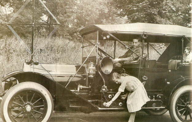
Tuning in NDBs is made more difficult because of the hand-capacitance problem. By tuning the station slightly lower in frequency than resonance, when the hand is removed the drop in capacitance increases the tuned frequency and hopefully the station will be then tuned to resonance. With a little practice it becomes almost instinct to tune 
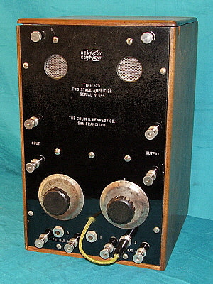
NBDs in this manner when using the Kennedy Universal operating 
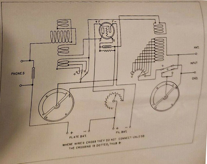
as an autodyne detector.
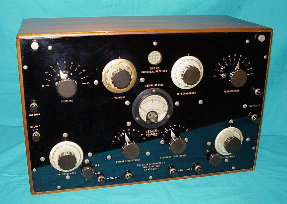
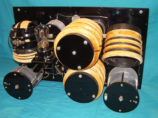
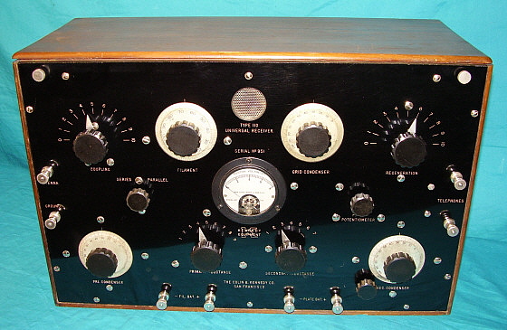
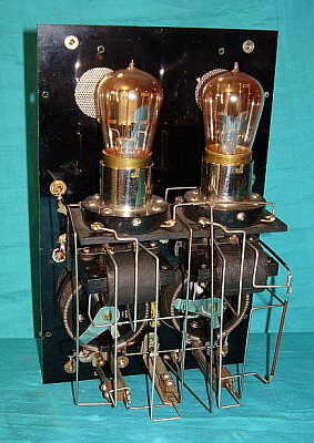
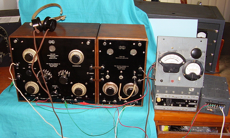
Log of NDBs received March 17, 2009 from 22:00 to 22:30 
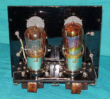
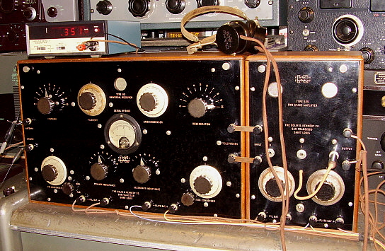
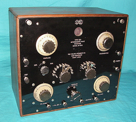
PDT using Kennedy Universal SN5403 with 525 amplifier.

   338kc - PBT - Proberta, Red Bluff, CA              368kc - SIR - Sinclair, WY
   338kc - RYN - Tuscon, AZ                                 371kc - TVY - Tooele, UT
   332kc - LBH - Portland, OR                               383kc - PI - Tyhee, ID
   335kc - CC - Buchanan AF, Concord,CA           385kc - WL - Williams Lake, BC, CAN
   329kc - TAD - Trinidad, CO                              389kc - YWB - West Bank, BC, CAN
   344kc - FCH - Fresno,CA                                  380kc - BBD - Brady, TX
   350kc - NY - Enderby, BC, CAN                       395kc - ULS - Ulysses, KS
   351kc - NO - Reno, NV                                      400kc - QQ - Comox, Van.Is.,BC, CAN
   359kc - BO - Boise, ID                                       404kc - MOG - Montegue, CA
   356kc - MEF - Medford, OR                              408kc - MW - Moses Lake, WA
   368kc - ZP - Queen Charlotte Is,BC,CAN          414kc - LYI - Libby, MT
   367kc - SX - Cranbrook, BC, CAN                     411kc - RD - Redmond, OR
   371kc - ITU - Great Falls, MT


NDB Stations tuned in March 29, 2009

LFA - 347kc - Klamath Falls, OR
CVP - 335kc - St. Helena, MT
DC - 326kc - Princeton, BC, CAN
ONO - 305kc - Ontario, OR
YYF - 290kc - Penticton, BC, CAN
XC - 242kc - Cranbrook, BC, CAN
GLS - 206kc - Galveston, TX
AEC - 209kc - Base Camp, NV
SF - 379kc - SF Int'l AP, SF, CA


Updating a "Dated" Kennedy Type 220 Restoration

I restored Kennedy Type 220 Intermediate Wave Receiver SN: 5118 in 1986,...over 30 years ago! At that time, I had to fabricate most of the parts that were missing. Consequently, this old restoration certainly could be improved upon now since I had acquired another Kennedy 220 that was in "rough" condition. The "parts set" 220 was a late-version with no serial number on its front panel. Its cabinet had most of the glue joints broken loose with large gaps showing and some warping of the wood. Inside, the General Radio-style filament pot was disconnected and its original shaft and knob were missing. An compression resistor (Bradleystat) had been installed (hole drilled in front panel, of course) to take the place of the GR-type pot. Several pieces of the nickel-plated hardware was missing. However, most of the parts that I had replicated for the restoration of SN: 5118 were present and were original on this "parts set."

Problem with the Original Restoration - When obtained, SN:5118 was missing the secondary coils that mount below the variometer. I had to make the form and wind these coils. The number of turns was an unknown so I based that on the dimensions that I extrapolated from photographs of an original coil set and observation of how the secondary coils looked on a Kennedy 110. Originally, the secondary coils were bank-wound but my reproduction versions were just layered coils. Although SN: 5118 seemed to work okay, it never performed as well as either the 110 or the 281. I believed that one performance problem might be due to the inaccuracy of this repro secondary coil form and coils. (I was to find out that this was only one of several problems.)

Additionally, the variometer I used in the first 220 restoration was from my "junk box." It was the correct type for the 220 but, in comparing the two variometers, I noted that, although the receiver connections went to the right places, the variometer terminals were in different locations. Variometers must be connected correctly, both internally and within the circuitry. 

Variometers are made up of four coil sets all connected in series. If everything is connected properly then the total L changes differently in each 90 degree quadrant. The total L increases in the + sine during the first 90 degrees of rotation and decreases in the + sine in the next 90 degrees of rotation. From 180 degrees to 270 degrees the total L increases in the - sine and from 270 degrees to 360/0 degrees it decreases in the - sine. The Kennedy regenerative receivers (and practically all other types) require the variometer to operate in this manner to allow tuning of the plate circuit which allows regeneration to occur using the grid to plate interelectrode capacitance of the detector tube as the feedback path. If the variometer is connected in any other manner, regeneration will either not occur or the feedback will be uncontrollable due to the total L operating within the incorrect quadrant of total L versus rotor position.

I also needed to check the values of the fixed-value mica capacitors and to confirm that the grid leak resistor was of a proper value around 2 meg ohms. This was more out of curiosity than anything else.

Proposed Solution - Since the 220 parts set did have its original variometer and the original variometer-mounted secondary coils, I could "transplant" these parts into SN:5118. Additionally, since these components appeared to have not been tampered with, I could verify the correct connections on a "stock" Kennedy variometer.

All other connections within the "parts set" that appeared to be original could be compared to SN:5118 to verify the wiring. (This turned out to also be a problem since the filament circuit had been modified.) Our goal was to have SN:5118 be wired as original and to perform correctly. Also, for this receiver to have the greatest quantity possible of original Kennedy 220 parts comprising the receiver. The "parts set" Type 220 would be built up using the repro parts to be a display piece.


photo left: The Kennedy Type 220 after its 1986 restoration. Looks good on the outside but inside several problems plagued this set.

Swapping the Variometer-Secondary Coil Assembly - This requires removing the dial. Then unsolder the buss wire connections to the detector plate and the phone condenser. The coil connections to the secondary inductance tap switch contacts have to be unsoldered. Then remove the two flat head screws that mount the assembly to the front panel. This procedure has to be repeated to remove the old assembly also. Install the replacement assembly and solder all coil connections to the secondary tap switch contacts and the buss wire connections to the detector plate and the phone condenser. That completes the swap. The photo right shows the new variometer installed.

In examining the two variometers, the old restoration "junk box" one and the replacement original, I noticed a difference between the two. The replacement original variometer was mounted upside down on the secondary coil form. This was why the terminals and connections appeared different from the first variometer. In checking two Type 110 receivers, both of those variometers were mounted as I had mounted the "junk box" variometer when I built the repro tickler coil form. In thinking about the relationship of the variometer rotor to the stator, it appears that there really isn't an "upside down" electrically. As long as the four coils inside the variometer are connected correctly (in series) the variometer will work. Testing the operation of the Type 220 did show that the variometer did adjust the regeneration as it should.

Filament Variable Resistance - Although this component appears exactly like a General Radio component, there is no identification as to the actual maker. Note that I don't call this component a "potentiometer" since there are three terminals on a "pot" and the variable resistance control only has two terminals. Acting as a series resistance, the voltage drop across the resistance is about one volt per one ohm of resistance DC, since the tube filament should draw one amp. Total R for the variable resistance is five ohms. An oddity was found on this component in that it had no "OFF" position. This is usually accomplished by insulating one end of the Ni-Cr wire but in this unit neither end was insulated. Therefore the filament voltage couldn't be turned "OFF." I added a heavy paper layer to the wire end under one of the terminal plates to correct the problem. I'm not positive that this component was the original part to this Type 220. It was mounted with only one screw and nut instead of three and it wasn't connected into the circuit (the Bradleystat was connected.) It appears to be the correct part with the exception of not having an "OFF" position.

Wiring Check - Although all of the connections seemed correct in both receivers, how the connections were accomplished differed. This appeared to be because of the relocation of the Series-Parallel switch from the left side of the front panel to a mounting next to the primary condenser. Also, the "parts set" tube socket mount was somewhat larger and had the grid coupling condenser located on top behind the tube socket while SN: 5118's tube socket mount was smaller and had the grid coupling condenser located underneath. Slight changes in the locations of the bends in the buss wire were also noted. It seems that the connections were correct but how the wiring was accomplished differed from early to late versions and may have differed slightly from assembler to assembler at the Kennedy plant.

Condenser Values - The grid coupling capacitor measured 500pf in both receivers. The phone condenser measured 1.5uf in both receivers.

Quick Operational Test - The Type 220 was tested "out of the cabinet" at first to see if everything was going to function okay. The first power-up was done without a grid-leak R installed - oops. Amazingly, I picked up all the normal AM BC stations. All that was noticed was an audible hum unless the detector plate was above +23vdc. Installing a 2 meg ohm grid leak resistor really helped reception with much louder signals and no hum regardless of the detector plate voltage.

Operating the Type 220 with the Type 525 Amp Reveals a Serious Problem - I connected a St. Louis version Type 525 audio amplifier to operate with the Type 220. When the B- from the Type 525 was connected to the B- of the Type 220, the tube filaments went out. The A power supply was being shorted. The only explanation would be a conflict as to how B- was referenced to either A+ or A-. I knew the Type 525 was not the problem since I'd operated it many times with the St. Louis Type 110 and it worked fine. The problem had to be with the Type 220. I checked that my wiring agreed with the schematic in Rider's PTSM, that is A- was connected to B-. I then physically checked the Type 110 and the Type 281 receivers and then the Kennedy 110 schematic, all of which had B- connected to A+. Again, looking at Rider's, that schematic shows A- to B-. Unfortunately, both of the Kennedy Type 220 receivers were modified in the filament area of the circuit with missing components on the first receiver and missing wiring on the "parts set." I changed the wiring in the Type 220 to agree with the "Kennedy standard" of A+ connected to B-.

The Type 220 was again set-up for testing by itself. The improvement in performance was very noticeable with much better regeneration action and improved signal strength. Next was to connect the Type 525. This time the audio output was very low. I tried the output from the first audio stage and it was much louder. This meant a problem in the last stage AF. Somehow, I had installed a defective UV-201 tube in the last stage (good filament but internally shorted.) The tube was even marked "NG" (No Good) so I should have noticed. Anyway, a good condition UV-201 got the entire Type 220 and Type 525 working correctly.

Update Oct 30, 2021 - It's been quite a while, nearly five years, since I did any work to a Kennedy apparatus but while restoring a 1938 US Coast Guard receiver, I needed a vintage interstage transformer. I remembered the Type 525 that I had paired with the Type 220 had two non-original interstages. While I was looking through the junk boxes for a suitable transformer for the USCG receiver, I came across a matched pair of interstages that looked similar to the original Kennedy types being that they were open frame types. Physically, they appeared to be the right size and, of course, both were vintage units and had good primary and secondary windings. I got the Type 525 down off the shelf and took it apart. Now, both interstages that were installed in the Type 525 were in good operating condition BUT they didn't match and neither one was even close in appearance to the original Kennedy transformers. I used one of these replacement interstages for the repair of the USCG receiver. I measured the mountings in the Type 525 and they were the same size as the matching pair of interstages I intended to use. During the "old" Kennedy amplifier repair, the radio repair guy from the distant past (probably a repair performed in the late-twenties) used hook-up wire to connect the interstages to the proper buss wires. These wires were removed. I mounted the two matching interstages and then proceeded to wire them into the circuit using 16 gauge tinned-copper buss wire, as originally was done, making all of the right angle bends and installing the buss wire as Kennedy assemblers would have done. The soldering technique at Kennedy was essentially a good quality "tack soldering" that had no mechanical support. Certainly this was popular during the twenties and all battery-set restorers have found their share of cracked and broken solder joints from this old method of assembly. BUT, I used this soldering technique anyway since it was original to the Type 525. I double-checked the hook-up but didn't power-up the amplifier. I put it back on the shelf with the Kennedy Type 220. BUT, it is ready for operation the next time the Type 220 is going to operated. Maybe another test like the one that follows,...


Operating the Kennedy Type 220/525 "Intermediate Wave" Receiver/Amplifier Today

As with the Kennedy Type 110 and Type 525 operation profiled in a section above, testing the Type 220 and Type 525 on the AM Broadcast Band isn't particularly challenging. Since the Type 220 tunes from 100kc up to 2000kc, the NDB stations are just about in the middle of the band three and provide a difficult test for the capabilities of the receiver. Setup requires operating the Type 220 as an autodyne detector and, like the Type 110, this does create some problems with hand-capacitance effects since the Type 220 is also completely without shielding. Additionally, "critical coupling" must be carefully set in order to maximize sensitivity in the receiver. For the most part the Kennedy Type 220 adjustments are basically similar to the Type 110 adjustments.

For the test we used a 6vdc 4A Lambda PS for filaments, an adjustable 0-30vdc 2.5A Lambda PS for the detector plate and an RCA Duo-Rectron for +90vdc for the Type 525 B+. The antenna was my ham station antenna that is 135 feet center-fed with open feed line that is shorted to create a "T" type antenna that is 94 feet of "shorted" open line with a 135 foot top hat (or maybe it's just a lot of wire!) Ground was the house ground (not the best but it's all that was available.) The 'phones were Baldwin Navy Type C.

As part of the initial setup I used a signal generator to find a few NDB frequencies and log the settings for best reception on the Type 220. I tested at 200kc, 250kc, 330kc and 400kc. This makes any large changes in frequency fairly easy to accomplish. I logged settings for Coupling, Primary L, Primary C, Secondary L, Secondary C and Regeneration. I used Series for signals below 500kc and Parallel for AM BC (same as the Type 110.)


photo above: This is the test setup for the Type 220 and Type 525. The power supplies are the adjustable Lambda (0 to 30vdc) with full metering used for the detector voltage. To the right is 6vdc 4A Lambda for filaments to both units. On the floor and not in the photo is the RCA Duo-Rectron B Eliminator that is providing +90vdc for the amplifier plates. The reproducers are a set of Baldwin "Navy" Type C phones. The Type 220/525 was setup in the upstairs hamshack.

The actual reception test was comprised of three listening sessions over three different nights. Each session was no longer than a half an hour. Usually, only "newly heard" NDBs stations heard were logged, meaning that after hearing and logging a station one night, we tried not to log it the next night. So, assume that "blow torches" (really strong signals) like FCH, CVP, BO and MOG were heard each night. Conditions on all three nights were good with moderate noise levels. Noise below 300kc was high preventing copy of NDB stations in that part of the spectrum.

NDB Stations Logged on November 16, 2016 - 19:00 to 19:30

1. BO  -  359kc  Boise, ID
2. MOG   - 404kc  Montague, CA
3. QQ  -  400kc - Vancouver Is., BC, CAN
4. FCH  -  342kc  Fresno, CA
5. CVP  -  335kc  St. Helena, MT

NOTES: Only five stations heard is not typical of this receiver's capabilities. Maybe I should try a different set of tubes for the next listening session. The next day I tested a couple of different sets of tubes and found a set of tubes that allowed the Type 220 to receive FCH 342kc during the day. This tube set should perform very well during the night session.

NDB Stations Logged on November 17, 2016 - 19:15 to 19:30

1. RYN  -  338kc  -  Tuscon, AZ
2. CVP  -  335kc  -  St. Helena, MT (previously logged)
3. STI    -  333kc  -  Mt. Home, ID
4. DC    -  326kc  -  Princeton, BC, CANADA
5. SBX  -  347kc  -  Shelby, MT
6. NY    -  350kc  -  Enderby, BC, CANADA
7. BO    -  359kc  -   Boise, ID (previously logged)
8. WL    -  385kc  -  Williams Lake, BC, CANADA
9. MOG -  404kc  -  Montague, CA (previously logged)
10. MW  - 408kc  -  Moses Lake, WA
11. ZP   -  368kc  -   Sandspit, Queen Charlotte Islands, BC, CANADA
12. YK  -  371kc -   Yakima, WA

NOTES: A different, complete set of tubes has made a tremendous difference. Twelve stations logged in 15 min. with better tubes (1-UV-200 and 2-UV-201.) Receiver much more sensitive now.

NDB Stations Logged on November 18, 2016 - 19:30 to 20:00

1. MEF  -  356kc  - Medford, OR
2. YQZ  -  359kc  -  Quesnel, BC, CANADA
3. SX   -   367kc   -  Cranbrook, BC, CANADA
4. ITU   -  371kc   -  Great Falls, MT
5. OT    -  378kc   -  Bend, OR
6. YWB -  389kc  -  West Bank, BC, CANADA
7. ULS   -  395kc  -  Ulysses, KS
8. QQ    -  400kc  - COMOX, Vancouver Is., BC, CAN (prev.log)
9.  LV    -  374kc  -  Livermore, CA
10. MNC - 348kc -  Shelton, WA

NOTES:  Total of 23 different stations logged in three listening sessions. Many stations like FCH, BO, MOG and CVP were copied on all three nights. No NDB stations were copied in the 200kc to 290kc part of the spectrum due to heavy static.

Follow-up - Collectors that use their Kennedy receivers know they are top performers on the AM BC band, given the consideration that they are regenerative receivers using pure-tungsten filament tubes. These NDB reception tests show that the Kennedy receivers can be used to receive other types of signals as well. One note on successfully listening to medium wave signals,...one has to remember that nowadays the spectrum from 15kc up to 500kc is extremely noisy and virtually all signals are digitally encoded requiring that a heterodyne be used to demodulate the signal. Although NDBs use MCW, the heterodyne allows better copy of these usually weak signals. It is difficult to receive most signals below 500kc unless you are in a very RFI-quite location and have an antenna that responds better to signals than to noise. Using a 1920s vintage receiver with only an outdoor wire antenna is a challenge but, fortunately, NDBs are still pretty easy to receive and decode* providing an excellent test for vintage receivers that tune below the AM BC band.

*Experience in copying weak Morse signals in QRN conditions helps immensely BUT, since the NDBs send Morse MCW so slow (10 wpm or less) and they repeat their call letters over and over and over, if you don't know International Morse you can write down the dots and dashes and then decode the letters later. Once the NBD call is known then use the website www.classaxe.com/dx/ndb/rna to verify the call, frequency and location of each NDB station copied.

For more information on Vintage Long Wave Receivers and how to successfully copy signals below 500kc go to our four-part web-article "Vintage Longwave Receivers." Navigation link on the Home-Index.


Kennedy Receivers in Dr. Royal Rife's Laboratory

Dr. Royal Rife's Kennedy Radio Equipment

 In the 1920s, Dr. Royal R. Rife began experimenting with the possibility that disease causing micro-organisms could be destroyed by exposing them to specific RF frequencies from oscillators driving a multistage amplifier to power a high voltage-gas filled ray tube. Most of the early work was carried out using Kennedy receiving equipment as the RF frequency generators (oscillators.) This can be accomplished by setting up the regenerative receiver in an oscillating condition and then coupling the desired output from the Antenna Input post. When the detector is oscillating, those oscillations are coupled into the Primary Tuner and then coupled onto the antenna. The oscillations can be a relatively high amplitude and are at the frequency that the receiver is tuned to. By using the Antenna Input post as the "Oscillator Output" the regenerative receiver can be used as a variable frequency oscillator. Frequency is controlled by the Secondary Condenser control and amplitude can be adjusted by either the Regeneration control or the Coupling control. Later, Dr. Rife was interested in the effects of modulated waveforms and used one receiver operating as an oscillator to modulate a second receiver also operating as an oscillator. This was accomplished by connecting the "carrier" oscillator-receiver's Antenna post to the Ground post of the 'modulator" oscillator-receiver and then taking the modulated waveform from the modulator-receiver's Antenna post. Whether using single waveform or a modulated waveform, Dr. Rife would then route the signal into a five stage amplifier to boost the output enough to drive a high voltage, helium gas-filled ray tube. The effects of the RF exposure on various micro-organisms from this setup were monitored in Dr. Rife's elaborate optical UV microscope (center on the bench.)

photo left: A vintage photo of Dr. Rife's laboratory showing the Kennedy 110/525 and 281 equipment (left,) and his elaborate UV microscope (center.)

Recreating Dr. Royal Rife's Multiple Frequency Generator

Our "Kennedy-Oscillator" experiment was requested by two well-known researchers on Dr. Rife's early work, Jeff Garff and Jason Ringas (Rife Research Institute.) The goal of the experiment was to show that such a setup as shown in vintage photos of Rife's laboratory would indeed produce the desired waveforms. We used our SF Kennedy 110 Universal receiver with its SF Kennedy 525 amplifier and our SL Kennedy 281 Shortwave receiver as the generators. We powered the receivers using various power supplies to provide the 6 vdc at 3 amps required for the 110/525 combination and the 6 vdc at 1 amp required for the 281. Separate B+ supplies provided +20 vdc for the detectors in each receiver and the +60 vdc required for the plates in the amplifier. Each receiver and the amplifier were set up using the pure tungsten filament tubes of the time, UV-200 soft detectors and UV-201 hard amplifiers. Rife listened to the receiver output with earphones - probably to verify that each receiver was oscillating and to monitor any unexpected changes in his adjustments. We did the same. We measured frequency, amplitude and harmonic content with modern equipment, e.g. spectrum analyzer, oscilloscope, digital frequency counters, etc. Stability of the setup and the waveform output was surprisingly good. The repeat ability and accuracy were excellent, output was very high and the sine waves generated were free from distortion and harmonic content. Our conclusion was though it seemed unlikely that the Kennedy set up would be accurate or stable, just the opposite was true - it was fairly easy to duplicate the frequency generation part of Rife's experiments using early Kennedy equipment and the results were surprisingly good.

Henry Rogers - June 11, 2007


photo left: The Kennedy 281 (top) and Kennedy 110/525 (bottom) set up with Lambda power supplies for the filaments and a homebrew eliminator for B+ requirements. The GR freq. counter is monitoring the 250kc signal from the Kennedy 110.

References:

1. Radio Manufacturers of the 1920s, Vol. 2, Alan Douglas - History of Colin B. Kennedy Co., Kennedy selling prices, early Kennedy models

2. Colin B. Kennedy Company - Instructions for Installation and Operation of Kennedy 110 and 525 - December 26,1922 - Instruction Sheet 110D - operation and set up

3. Rider's Perpetual Troubleshooter's Manual - First Edition 1931, also VOL. 1 - Schematics of Type 110, 220 and 281, (these schematics are fraught with errors) - Audio Amplifiers are not in Riders.

4. The Official Radio Service Manual - Hugo Gernsback Editor, published 1930 - Schematics for Type 110, 220 and 281. These are the schematics that Rider used in his manual (one year later.)

5. Thanks to all of the collectors who, over the years, have let me examine their Kennedy Apparatus: Paul Giganti, Fred Winkler, Bill Wakefield and many others

6. Dr. Royal Rife information from: The Rife Research Institute, Jason Ringas and Jeff Garff, who supplied photo of Rife's lab


Henry Rogers/Western Historic Radio Museum © March 2009, updated layout and added more information November 2016, NDB reception test results for Type 220 added Nov 2016,


Return to Home Index


Radio Boulevard
Western Historic Radio Museum

 Vintage Radio Communication Equipment Rebuilding & Restoration Articles,

 Vintage Radio History and WHRM Radio Photo Galleries

1909 - 1969

- 60 years of Radio Technology -


This website created and maintained by: Henry Rogers - Radio Boulevard, Western Historic Radio Museum © 1997/2023