Radio Boulevard
Western Historic Radio Museum
 

W6MIT Transmitters
Professionally Engineered Homebrew Ham Rigs
 

Model 45098 "The Big Rig"
Basic Design, 2018 Sale, 2023 Purchase, Missing Audio Chain,
Getting "The Big Rig" On the Air, Check-out, Missing Procedures,
The Bogen CT-100C Audio Amp, Microphones, Updates


Model AM100 "The 1625 Rig"
Basic Design, Mechanical Layout, W6MIT 2007 Upgrades,
 2018 Purchase, Performance, WA7YBS 2023 Upgrades,
New Fans for Reduced Noise and Better Air Flow

by: Henry Rogers WA7YBS - Radio Boulevard


Red Hot and Luv'n It!

The 4-250A in "The Big Rig" producing 300 watts RF output power

This write-up profiles two homebrew amateur radio transmitters built in the late-1990s by John Svoboda, W6MIT. These two transmitters AREN'T your usual amateur projects that were typically hamster-level built from junk box parts. These two transmitters were professionally engineered electronically, the mechanical layout masterly accomplished with superb sheet metal creations that were finally assembled into fully-functional units with top performance that always garner great signal/audio quality reports. I've known John W6MIT "over-the-air" for over twenty-five years and have met him for "eyeballs" a couple of times at the N7RCA swap in Minden, Nevada. Little did I know that I'd end-up with two of his masterpieces of ham radio homebrew transmitter execution, yet here they are. I've owned the little 70 watt "1625 Rig" since 2018 and I was finally able to obtain John's 300 watt "Big Rig" in June 2023. So, here are the details on these two rigs, their design, construction and performance,...and what was involved in putting them back "on the air." By the way, John W6MIT currently lives in Grants Pass, Oregon and, although retired from amateur radio, is still in contact with many of our ham-colleagues by other technologies.
 

W6MIT Transmitters - Professionally Engineered Homebrew Ham Rigs


Model 45098 "The Big Rig"

"The Big Rig" design pays homage to the AM-BC transmitters from the 1950s-1960s,...albeit greatly reduced in size and weight. Perhaps there's also a little military influence provided by the T-368 exciter. The transmitter uses a single 4-250A PA modulated by a pair of 572B tubes. The PA has +2000vdc on the plate (adjustable) while the 572B plates run at +1500vdc. "The Big Rig" RF power input is about 450 watts and the conservative AM carrier output power is minimum 300 watts.


W6MIT Model 45098 - Appearing like a miniature, 4 foot tall AM-BC transmitter, "The Big Rig" produces a 300 watt carrier output AM signal. The T-368 Exciter uses a Collins PTO and permeability-tuned multiplier stages with an output stage that drives the 4-250A directly while accurately displaying the transmitted frequency with a mechanical-digital readout. The audio speech amp is an external  Bogen CT-100C the output of which drives the high power modulator directly. Lexan windows allow the viewing of the 4-250A PA tube and the 572B modulator tubes.

"The Big Rig" - Basic Design - The "heart of the transmitter" is the Exciter unit from a military T-368 for frequency control. The Exciter uses a Collins PTO and permeability tuned multiplier circuits for determining output frequency and employs a mechanical-digital direct frequency readout. The Exciter deck also has the medium level power supplies for operation of the Exciter and for the control circuitry. Most of the transmitter operational control circuitry is by "push-buttons" that are located on the Exciter deck panel. The push-buttons actuate various internal relays that perform the actual "switching." The transmitter can also be operated semi-remotely using a wired desk-top controller unit.

The metering on the PA panel allows monitoring PA plate I and PA screen I on the large meters. These meters can be switched using the small toggle switches to monitor either respective current or voltage levels for the PA plate or screen. PA filament voltage and PA grid drive are monitored on the small square meters. The large scaled vernier knob on the lower left of the PA panel is PA Load (adjusts an air variable C) and the other large knob center-right works a "turns-counter" that adjusts the vacuum-variable C for the PA Tune. The small knob to the right adjusts the PA filament voltage. The toggle switch to the left of the PA filament adjust knob is "Adjust-Normal" that removes the screen voltage in the "Adjust" position for tuning the transmitter in a low-power mode. The PA screen voltage and the PA grid bias voltage are produced by a power supply onboard the PA deck. There is a "Screen High-Low" toggle switch on the back of the PA deck. The "Low" position reduces the +400vdc screen voltage by 50% to allow test operation at lower power output (also requires reducing the PA plate voltage and loading for PA current of 100mA for about 100 watts output.) Low power should only be used for testing for short time periods. The 4-250A tube must always be operated at or near maximum specs in order to keep the tube in good condition. 

The Exciter panel meter monitors the 5763 plate I on the exciter (the original odd-ball type 6000 tube that the T-368 Exciter used, with its 25.6vac heater voltage requirement, was replaced with a standard 6.3vac heater tube, the 5763, by W6MIT.) The white push button in the upper right section of the panel just operates the Exciter "keyed" for zero beating a desired frequency. The yellow push button selects Phone or CW. The two vertically aligned white push buttons are for selecting Transmit or Receive operation. This function can also be performed remotely using a wired connection from the terminal block on the rear chassis to a desk-top T-R control panel. The red push button lower left powers the Exciter deck and low voltage to the PA deck. The small round red push button turns the Exciter on or off and can allow just the Exciter to be powered to allow a "warm up" period.

The Hi Power Modulator deck has a db meter to monitor the audio input on the left and a 572B plate current meter for modulator output on the right. This meter also has an associated toggle switch to select reading either Mod pI or Mod pV. The external audio chain speech amplifier can be input to the Aux Audio jack on the front of the Modulator panel or in can be routed to the rear terminal block on the modulator chassis. The two pots are db meter calibrate on the left and 572B grid bias on the right (they are screwdriver adjustments and have threaded chrome covers.) The grid Bias power supply is onboard the Modulator deck. The second phone jack to the right of the Aux Audio is for monitoring the audio input to the modulator with external test equipment.

The power supply deck at the bottom of the rack has the +2000vdc PA Plate supply that can be easily disconnected (unplugs) and then removed to lighten the weight of the transmitter for moving (PA Plate supply weighs about 90 lbs.) Also in the power supply deck is the +1500vdc modulator plate supply and the +24vdc supply for the power control relay circuitry. This power supply can also be removed if necessary. The Variac is connected as a variable R and allows adjusting the PA Plate voltage during set-up (PA plate voltage can be monitored on the PA plate meter if switched to the "voltage" position.) Breakers and fuses are panel mounted. The breakers must be switched on prior to powering up the Exciter, Modulator and PA decks.

The PA deck and the Modulator deck are fully enclosed shielded units. The Exciter deck and the Power Supply deck are open. Note in the photo below showing the rear of "The Big Rig" that the PA deck, the Exciter deck and the Modulator deck are on side rails mounted to a large frame on each side of the rack. This allows easy extraction of these decks from the front of the transmitter for servicing. All deck panels are equipped with grab handles. The air ducting has to be disconnected along with a couple of cables but the harnesses have extra length for pulling the decks out enough for servicing the tubes. There are three cooling fans, one in the PA deck, one on the side of the Modulator deck and the other is in the power supply deck with flexible aluminum ducting for routing more air to the PA deck. Additionally, the bottom of the PA deck has an exit hole that, due to the air pressure in the PA compartment, directs the air flow around the 4-250A and through its base vents and through the socket where the air then continues to flow throughout the cabinet. At one time there was another fan on the back of the Modulator deck but John removed that fan due to excessive noise (the side mounted fan on the Modulator deck was added later.) The spacer panel between the Exciter deck and the Modulator deck is to allow proper air flow through the cabinet. The cabinet is an enclosed relay rack with hinged back door with two latches. Rack height is 48" but with casters, total height is 50" tall. There are exit holes on top and on the left side for cables to enter and exit as required. The heavy-duty AC power cable exits through a hole in the rear lower base of the rack.

"The Big Rig" - Required External Audio Components - The modulator, being a "high power" modulator, required an external speech amp. The external audio chain would drive the high power modulator input transformer (with an 16Z primary) that then provided a hi-Z output to feed the grids of the 572B tubes. Originally, "The Big Rig" used a McIntosh 50 watt mono-block amplifier as the intermediate level speech amplifier with its 16Z output driving the 16Z input transformer in the high power modulator. The first design of the Model 45098 had a built-in audio level limiter to prevent over-modulation but that was soon replaced with external audio level control at the speech amplifier. The low-level speech amplifier section consisted of a CBS Volumax Limiter unit in combination with an Apex-Compeller speech processor unit and an adjustable Ross 31 band equalizer. Between the audio chain and the input to the McIntosh was a Modulator Driver that matched the 600Z balanced output of the audio chain (BC standard) to the input impedance of the McIntosh. Additionally, there was a homebrew "transmitter controller" that interfaced with the Model 45098 that allowed semi-remote control from the operating desk providing PTT, receiver muting, remote inputs with level controls and remote control of a Harris automatic antenna coupler. A Shure four-channel audio level mixer was used for multiple audio sources. Another piece was the homebrew Modulation Monitor.

Note that I deliberately used the "past tense" in this "Required External Audio Components" paragraph since none of these pieces are any longer part of "The Big Rig" audio today. All of the external audio chain components were separated from the transmitter and sold off about five years ago (2018.) The Harris antenna coupler, the modulation monitor and the desk top remote controller are also gone.

"The Big Rig" - History - W6MIT designed and built Model 45098 in 1998. It went though several design changes and updates over the next 20 years. The transmitter was located at John's QTH in Rescue, California, a small town outside of Placerville, California. John used to have regular skeds on 160M, he would check into several AM nets on 80M and was a regular on the one West Coast AM net on 40M. I probably first heard "The Big Rig" on the old Saturday Morning AM net on 3870kc at 8AM. That net was started by NU6AM, KØEOO/6 and myself, WA7YBS, back in 1994. The reason for the Saturday morning time period was that I was located in Virginia City, Nevada at the time and was dealing with a lot of TVI complaints from just one very vocal neighbor that, while two blocks away, apparently was too close to my house (common in Virginia City or any old town.) The TV addicts had every single room in their two-story, 100 year old house wired for cable TV (of course, with several un-terminated outlets) and were watching TV constantly on a crummy Macy's television set via the decrepit privately-owned cable-TV system that Virginia City had installed back then (even the cable-TV engineer told these TV-addicts their installation was the cause of the TVI but that didn't stop their complaining.) Anyway, the VC TV watchers were normally still in bed at 8AM on a Saturday morning so that was when we had the AM net. "The Saturday Morning Early Bird 3870 AM Net" became very popular over the next 20+ years until, in 2015, two California high-power SSB operators decided they wanted to use 3870kc at 0800 on Saturdays for their high-power, quasi-telephone call ragchew causing unrelenting QRM. This was, of course, deliberate interference, which if AM operators are the victims there's nothing that can be done to remedy the situation however, if the reverse happens, it seems to be taken as a capital offence. At any rate, the Saturday morning AM net was wiped-out and destroyed. W6MIT had been a fairly regular check-in and I'm sure I first heard "The Big Rig" then. Up to about 2018, John would regularly check into our Vintage Military Radio Net on Sunday mornings on 75M, though he used a modified B&W 5100 transmitter most of the time on that net.

Photo Right:  W6MIT Model 45098 "The Big Rig" looking at the inside with the "back door" open. At the top is the fully enclosed PA. Next down is the Exciter deck with the Exciter PS. Next down is the fully enclosed Modulator deck. At the bottom is the +1500vdc/+24vdc PS (left) and the +2000 PS (right.) The metal flex ducting routes the blower in the +1500vdc power supply up to the PA deck. The hole in the bottom of the PA deck is to allow the exhaust air from the fans after the air has blown through the base holes and socket of the 4-250A PA tube to exit the deck and to circulate the air around the Exciter deck and through the rack cabinet.

W6MIT 1998 Photographs of "The Big Rig" Interior

photo left: "The Big Rig" PA deck showing the +400vdc Screen and -200vdc PA grid bias power supply on the right along with the fully shielded meter compartment up front. The vacuum variable capacitor (blue-center) is the PA TUNE part of the output network. The vertically mounted L is the plate choke. The tapped L (white ceramic form) is the inductor part of the output network. Underneath the chassis is the PA LOAD air variable capacitor (see last photo in this series of five.)

photo right: "The Big Rig" PA deck as viewed from the back showing the rear connections. The terminal strip provides input connections for low voltages and switching. Above the terminal strip is the Screen voltage High/Low switch. The ceramic +2000vdc terminal isn't visible very well at this angle (it's below the fan.) The RF output SO-239 is to the right (top connector) and below it is a BNC connector for the receiver's antenna input connection. During transmit the antenna relay not only disconnects the receiver's antenna input, it also grounds the receiver antenna input (double protection for the receiver's antenna input section.) The connector below and to the right of the fan is for the Exciter drive input. The gray potted iron is the screen choke.

photo left: "The Big Rig" front and top of the Exciter deck. On the right half of the deck is the T-368 Exciter. The PTO is far right, then the multiplier slug racks and then the tubes. The Exciter power supply is on the left of the deck. The power supply provides +380vdc for the plate of the 5763 Exciter output tube, a -70vdc bias voltage and 6.3vac for multiplier tube requirements in the Exciter. Also, +275vdc for the multiplier plates along with a regulated +150vac (0A2 tube) for the PTO tubes and 6.3vac for the PTO tube heaters.

photo right: "The Big Rig" view of the Exciter deck from the rear. There's a Jones plug on top of the chassis for power to the Exciter. The brown terminal strip provides other inputs and outputs to the other decks for switching. The other terminal strip connects voltage into the Exciter switching for transmitter control. The rear mounted Jones plug is for the remote receiver muting function actuated by the PTT line. The 1/4" phone jack is for a telegraph key for CW operation.

photo left: "The Big Rig" showing the underneath of the PA deck. Note the angled-drive with several joints and a right-angle gearbox for the PA TUNE function with the turns-counter drive at the front and the vacuum-variable capacitor toward the rear of the chassis. The four gang air variable on the right is the PA LOAD capacitance. The "iron" provides the 5vac for the 4-250A tube filament.


These five photos were taken by W6MIT in 1998. They were in with the documentation in "The Big Rig" binder. Apparently, W6MIT didn't photograph the Modulator deck since there weren't any photos in the manual-binder. 


"The Big Rig" Initial 2018 Sale

In 2018, John, who was then in his early eighties, couldn't deal with the upkeep and maintenance required for his acreage in Rescue so he decided to sell his property and all of his gear and move into a "senior housing" apartment building in Placerville (but he now -2023- lives in Grants Pass, Oregon.) Some of the sales were handled by a mutual friend, KBØW/6 (who now lives at Lake Tahoe,) and some of the gear was sold to "Ham & Hi-Fi" in Sparks, Nevada (they did a "pick up" from John's QTH) for their own eBay and local resale business.

Ham & Hi Fi is where I first saw "The Big Rig" in person. I was seriously intent on purchasing W6MIT's "Big Rig" transmitter. I had been informed that the "W6MIT gear" had just come in at H&HF with a telephone call from their technician. I told the tech that I'd be down the next morning. When I got to H&HF the next day I was informed that "the big transmitter" had already been sold. WHAT!?!

I couldn't believe it! The W6MIT gear had only been at H&HF for a day and I had thought "nobody's ever interested in homebrew gear" so there wouldn't be any problem with all of the W6MIT gear still being available. But, although not yet picked up, "The Big Rig" had already been sold "sight unseen" to WA1ICI/7 based on a tip from KB6SCO who saw the transmitter at H&HF the afternoon before and immediately telephoned WA1ICI/7, urging him to buy it "sight unseen."

Fortunately, I knew John Atwood WA1ICI/7, who lived in Yerington, Nevada, so that meant I could easily "keep tabs" on "The Big Rig."
 

Acquisition of the W6MIT AM100 Transmitter - "The 1625 Rig"

"The 1625 Rig" April 2018 Sale - Lucky for me, even though I was disappointed about the sale of "The Big Rig," I didn't let that deter me from purchasing "the other" MIT-rig. As expected, nobody was interested in W6MIT's little 75 watt "1625 Rig." Maybe it was the "Ugly Duckling" of the two homebrew MIT transmitters. H&HF had never even moved it from where they unloaded it. It was literally right next to the roll-up metal door at the back of the building. I had sold H&HF a couple classic receivers (a Mackay Marine 3010C receiver and a R-1051B USN receiver) and had them take $150 out of my total payment to cover the purchase of "The 1625 Rig." Since this little transmitter was of no interest to anyone and it essentially came right from W6MIT's shack, it was complete and hadn't been tampered with at all. I gave it a quick check out at home,...well,...out in the shop using a dummy load. Then, with the antenna connected, I was quickly able to put it on the air. That was April 10, 2018. Nowadays, the "1625 Rig" is instantly recognized when I use it on the air because of its high-quality audio performance. It's a LOT of transmitter in a small package. I use "The Little Rig" with a collinear array antenna to help with its near-QRP 75 watt output. More details on "The 1625 Rig" further down in this article but the photo to the right shows the little transmitter.


"The Big Rig" 2023 Purchase History - June 16, 2023

All of the hams involved in my acquisition of "The Big Rig" are named John. There's John W6MIT. Then there's John WA1ICI/7. Then there's John KB6SCO. To keep the Johns identified correctly, I'm referring to them by their name and ham call suffix. Therefore it's John-MIT, John-SCO and John-ICI. Or, I might reverse it and call them MIT-John, SCO-John or ICI-John. Or, I might just use their ham call suffix, MIT, SCO & ICI.

The 2023 Purchase - About once or twice a year I'd run into John-ICI at a ham swap meet and I'd usually ask him "how's it going with the W6MIT Big Rig?" But ICI was always having a lot of trouble with his large antenna system that was strung between two 60' tall wooden power poles on his property. Also, with his vast multitude of other projects and numerous distractions he really never had the time and hadn't made any progress with the transmitter. In June 2023, I was over at my old friend John Lawson KB6SCO's QTH in Dayton and the subject of the W6MIT transmitter came up. SCO-John was pretty good friends with ICI-John so I asked SCO if he knew anything about the progress on "The Big Rig." SCO related that as far as he knew it was still just setting there in ICI's shack and had never even had AC power applied to it. I asked SCO to put out a feeler to ICI about the possibility of him selling "The Big Rig" to me. Surprisingly, I got a call the next evening from ICI and a deal was made on the phone. I basically paid John-ICI what he had paid H&HF for the rig and pick up was going to be on Friday, June 16, 2023, at the WA1ICI/7 QTH in Yerington, Nevada.


View of Mason Valley and the area east of Yerington as seen from the WA1ICI/7 QTH

Yerington, Nevada is located about 60 miles SE from Dayton. The John Atwood WA1ICI/7 Yerington QTH is fabulous. It's like an incredibly huge electronics museum-repository housed in an ultra-cool 1970s-style Nevada ranch house of 4000 square feet located on 15 acres with an additional couple of "densely packed" large outbuildings, all set on the property that features panoramic views of Mason Valley and Yerington. We toured through ICI-John's vast menagerie of all types and all vintages of electronic gear, all in various states of completeness from really nice 1920s battery radio sets with horn speakers up to some very modern equipment. Some sets were in beautiful shape while others were partially disassembled incomplete units. There were several computer stations where John-ICI maintains his website https://www.one-electron.com and keeps inventory on many thousands of parts (NOS vacuum tubes, NOS vintage ICs and many other types of components along with online vintage documentation.) There were five work benches, all with projects on each bench in various states of completion (including a beautifully designed and built RTTY demodulator.) And, in a back room, a true audiophile's set up with a special-built experimental high fidelity wooden horn speaker.  >>>

>>>  We finally ended up in the ham shack area where, in addition to a very large 1947 RCA Projection Television (that was partially disassembled) along with a working ham station (using a smaller antenna) and a partially disassembled Model 19 Teletype machine, ICI-John had "The Big Rig" stored. Everything that John-ICI had gotten in the purchase of "The Big Rig" from H&HF in 2018 was there in the ham shack, waiting for me to do the "pick up."

"The Big Rig" Revelation - Now I could see why, in the past five years, there hadn't been any progress in getting "The Big Rig" on the air. I had always thought everything was present with the transmitter and all that was required was check-out and hook-up. That definitely WASN'T the case. Quite a while back when talking to John-ICI about "The Big Rig," he told me that the 50 watt McIntosh monoblock amp that W6MIT had used wasn't with the gear when he had purchased it. But, not just the McIntosh was gone,...ALL of the "audio chain" gear that W6MIT had used was gone. Nothing remained,...not even the cables. Also, the desk top transmitter remote controller was gone. I knew that the Harris antenna coupler had been sold about five years before along with a few other pieces of W6MIT gear (like his receivers, the NC-183D and the R-390A along with his B&W 5100 transmitter) but I had always thought "The Big Rig" had basically stayed intact, only requiring some type of audio amplifier, but that certainly wasn't the case. Luckily, the most important parts of the documentation were still with the transmitter. That would be most of the schematics and most of John-MIT's notes.

Just like ICI-John's Ham & Hi-Fi purchase five years earlier, I got just "The Big Rig" transmitter with some of the documentation (although, John-ICI had acquired a parts set T-368 Exciter that was included in my purchase.) NONE of the peripheral audio devices or the remote controller were included because they were never present even back when John-ICI made the original 2018 purchase. I now could see why he really hadn't gotten very far in putting "The Big Rig" on the air,...it was because it was missing so many of the important pieces of necessary peripheral equipment.


The Original (and now missing) Peripheral Equipment

A Review of the Missing Audio Chain Equipment

CBS Volumax and Apex Compeller (Top and second down in photo) - John-MIT was preventing transmitter over-modulation at the audio input using the following equipment. The CBS Labs Volumax was a limiter to prevent audio peaks from over-modulating the transmitter. Replacing the Volumax would be expensive. Devices that are of interest to audiophiles are always expensive and anything broadcast audio related is also in that over-priced category. However, every recording studio will have several compressor-limiters as part of their equipment. It seems that these recording studio pieces aren't of much interest to audiophiles (only musician-audio types) so the prices are reasonable for a usable compressor-limiter. One of these devices could take the place of the missing and expensive Volumax and the Apex Compeller speech-processor (cheap) that W6MIT had been using.

Ross 31 Band Graphic Equalizer (third down in photo) - This was another one of the original pieces that was missing. I have a stereo 10 band equalizer that could work okay. But, even a Ross 31 band equalizer isn't usually very expensive. 

Shure Four Channel Audio Mixer (fourth down in photo) - MIT-John also had this audio mixer that he used for mike inputs and playing back "on the air" recordings. Although not a necessity, I do have a Broadcast Electronics, Inc. 4M50A Audio Console that came out of Carson City, Nevada radio station KPTL (the KPTL call is now defunct. The new station owners are so obtuse they got a new call for "their new station" not realizing that "KPTL" stood for "Capital" as Carson City is for Nevada. They changed the format from decades of "golden oldies" to the locally pervasive country-western crap. Also, the dual vertical antenna array was taken down and replaced with a cheap flagpole vertical. Idiots, and they wonder why nobody listens to their station now.) Anyway, the 4M50A is a very small desk top audio pre-amp and mixer unit packed with a lot of capabilities. All 1987 op-amp technology. It does have some interesting possibilities since it would allow using a variety of low-Z AM-BC mikes to interface to the audio chain.     >>>

>>> Desk Top Transmitter Controller - (bottom piece in photo) - I don't know why this piece was missing. It probably was included with the Harris Antenna Coupler sale since the right-half of the controller did power up and work the Harris coupler. The remote controller was divided into two sections. One section was just to power and operate the Harris antenna coupler. The W6MIT transmitter can be operated without the remote controller and as far as the Harris Antenna Coupler, I'll run the transmitter output directly to a manually operated antenna coupler. The other section of the controller operated the PTT line remotely. Since "The Big Rig" doesn't provide any receiver muting function, MIT-John built additional power supply circuitry in the Transmitter Controller to actuate its internal auxiliary relay from the transmitter's PTT function and that provided muting/standby functions for up to four different receivers. Also, a remote audio line in with level control and monitor output was provided. I ultimately will probably have to build up part of this Remote Transmitter Controller for the receiver muting operation and perhaps for the desk top PTT function. Although not absolutely necessary, it would be convenient and it's easily built since no special parts or components are required.

Carvin 87-S - MIT-John used a professional-looking, large diaphragm microphone. Although these look like the expensive Neumann 87 microphones and they do have excellent specs, they aren't priced like the genuine Neumann mikes. GTZ also makes a copy of the Neumann 87 that sells for a very reasonable price,...brand new. These types of condenser mikes require a separate power supply that's included with the mike when purchased new. However, this type of mike isn't a necessity since I have several high quality mikes available.

McIntosh 50W Monoblock Amplifier - MIT-John used a solid-state 50W monoblock audio amplifier made by McIntosh. It was probably the very first thing separated from "The Big Rig" and sold. There was also another piece that interfaced between the Audio Chain output and the McIntosh input that (I'm guessing) matched the 600Z balanced output of the audio chain to the input impedance of the McIntosh. This Modulator Driver is also a piece of missing equipment. In my collection of gear, I have a mint (factory built) EICO HF-20 Williamson Ultra Linear 20 watt audio amplifier. I think the conservative 20 watt rating (actually 36 watts peak) could drive the Modulator adequately.   >>>


50 Watt McIntosh and Modulator Driver

>>>  I'd probably have to make a matching device like John-MIT made if I used the 4M50A as the audio speech amp since it has the standard BC 600Z balanced output. Although the EICO is an "integrated amp" it does has a Tape Output jack that was intended for monitoring while recording and this jack is connected at the Loudness control and that's the input to the higher level audio section of the amp. Using the Tape Output as an "input" to have the EICO HF-20 become a monoblock amp was a very popular hook-up in the Hi-Fi days in the 1950s.

That could work,...but,...what a hassle.

Do I Really Want to Emulate an AM-BC Transmitter?

Audio Reality - So, that was the W6MIT audio chain. Though I could probably use the Broadcast Electronics 4M50A as a multi-channel audio preamplifier, purchase a compressor/limiter to control audio peaks and prevent over-modulation then also add some type of equalizer and then use the EICO HF-20 as a monoblock amplifier, that's four pieces of equipment all with interconnections,...it seems overly complicated. Also, it seems to be a waste of the HF-20 since only the higher level section would be used and all of the impedance matching and low level amplifiers would be wasted. I do use the HF-20 for playing records (78s, Victor Musical Masterpiece Series mostly, played on my Gates CB-11 BC turntable with GE VR cartridge and then using a Jensen KB Series bass reflex box with 15" Jensen coaxial speaker - real early fifties hi-fi,...equipment that is,...the recordings are much earlier.) Besides, I don't really even want to try to achieve AM-BC audio, so I don't want to get "carried away" with trying to duplicating John-MIT's setup or trying to emulate an AM-BC audio chain.

A Possible Simple Solution - In doing research on audio amplifiers, I found everything that related to High Fidelity music reproduction, especially vacuum tube based gear, was exorbitantly priced due to interest from audiophiles, vacuum tube enthusiasts and guitar-amp guys. I had an idea that evolved from the question,..."what type of good quality audio amplifier wouldn't be of interest to audiophiles?" The answer? Public Address amplifiers have never been of much interest to Hi-Fi audio types because the specs for these types of audio amplifiers are usually not really high fidelity since all of the equipment was designed primarily for voice-over-microphone amplification and not high-quality music reproduction. Add to that, looking for a solid-state type of PA amp would eliminate the vacuum tube aficionados. In reality, all a ham AM transmitter needs for a speech amplifier is a good quality unit with low distortion that reproduces a voice communications bandwidth at an output power sufficient to drive the high power modulator. That can be easily achieved using just a single piece of equipment.

Using a Bogen CT-100 Public Address Amplifier - The Bogen CT-100 Series of Solid-State Public Address amplifiers were designed for voice-microphone amplification. They have a built-in 10 band equalizer. They have built-in adjustable 0 to 30db speech compression. The CT-100 is rated at 100 watts output with 50hz to 15Khz bandwidth at less than 2% distortion (that sure wouldn't appeal to anyone interested in High Fidelity!) The resulting audio would probably be equal to (or maybe better than) most ham AM signals heard these days. Since the CT-100s are PA amplifiers and they use solid-state op-amp circuitry they aren't of any interest to audiophiles. The prices are usually very reasonable even for good condition, working examples (most are priced from about $50 up to maybe $100,...but it's the shipping that can ruin a good deal since they weigh close to 30 pounds.) So, I purchased a used CT-100B Bogen 100 watt PA amplifier. Mike inputs use Cannon XLR connectors and the mikes can be either balanced lo-Z or unbalanced hi-Z types. There are four to six channels that can be mixed if desired. The compression range is a screwdriver adjustment on the front panel. The equalizer range is 80hz to 5000hz in 10 bands at +/-12db compensation. Audio output is 4, 8, and 16 Z-ohm or 25v/70.7v line levels accessible via screw terminals. The 100 watts available should provide plenty of headroom for driving "The Big Rig" high-level modulator. 

The First CT-100 is a Dud - The first Bogen, a CT-100B arrived July 12, 2023. Though described as "working as intended" it actually turned out to be entirely non-functional with wires disconnected on the inside (and lots of spider webs indicating nobody had even bothered to look inside - unbelievable!) I guess the "working as intended" actually was the seller's subjective imagination and not reality. I should have paid more attention to the caveat of the first three words of the sentence,..."Seems to be working as intended." These amps are so cheap, I just bought another CT-100C that was guaranteed to work. Half the price of the first Bogen, so hopefully it will live up to its description (and it did!)

 
Unfinished Documentation - Although the transmitter manual is in a three-ring binder, it is just one of three binders that were originally with "The Big Rig." The three binders were "450 Watt AM Transmitter," "Harris Antenna Coupler," and "Big Rig Audio." Only the "450 Watt AM Transmitter" binder was present but I'm not really sure that all of the documentation that was originally in that binder is present now. For example, there are no operating instructions, no "tune up" readings, no wiring diagram of the rack or the interconnections, the schematics don't appear to be "finished products" because most of them don't have any component values or voltage levels. The schematics look like they were drawn with a computer program and that might be why sometimes components don't have values shown or voltage outputs specified. Where were John's original hand-drawn schematics?

It could be that some of the document pages got moved around into the other binders sometime in the past for some reason and that accounts for the incomplete nature of the docs. When compared to the W6MIT documentation that was with the "1625 Rig" this "450 Watt AM Transmitter" binder looks unfinished. However,...ALL of the important information IS present but it's mostly in the form of notes, tube specifications, charts and graphs that are hand-drawn for the most part. So, while not a "quick reference" document, certainly all the information necessary for operating "The Big Rig" is in the binder.    >>>

>>>  Now, there aren't specific "Operation Instructions" or "Tune up Procedures" in the form of paper documents. John didn't need them and I don't think he really thought about selling "The Big Rig" until he decided to move and then he didn't have the time nor the inclination to finish "The Big Rig" documentation. However, if one has sufficient theory background with some experience and is familiar with operating medium power transmitters that use similar tubes and similar voltage levels, John's notes and graphs make sense and are easy to follow.

To make the documentation an easy to use reference for me, as I compile John's notes and get a feel for operating "The Big Rig," I'll write a "Tuning Procedure" and that should help in the future. Also, the individual wire identification of each harness uses a paper document with a letter code, source/destination and a wire color code listed in columns. I find this very hard to use as a reference, so I plan to add Thomas&Betts IDs to the wires in the harnesses and those ID numbers will be used as the reference to where each wire connects. This would allow easy removal and reinstallation of an individual deck for maintenance.

As I've said, ALL of the information necessary IS present,...it's just not a finalized document. I'll add my notes, add voltage levels and component values to the schematics and print-out my tuning procedure to install in the binder and probably other stuff as needed (like a component location drawing.) Ultimately, the binder will be a mostly complete document that should allow almost any experienced ham to setup and operate "The Big Rig."

 
Shop Antenna Needed - An Integral Part of this Entire Project - First, I need to put up an antenna for the shop. The heavy, wet snow storm with strong winds on New Year's Eve (Dec 31, 2022) had destroyed both of my large wire antennas. The collinear array was the easiest to repair and I had it back up and working within a week despite the winter weather (that left snow on the ground for two months.) The collinear array was still operating as the shop antenna but I had been thinking for about a year of changing it to become the antenna for the house upstairs stations. That reconfiguration only took a few days in February to accomplish but that left the shop without any transmitting antenna and it's been that way for six months now. Most of the operating in the shop happens during the summer months so I do have to get busy and put up a new shop antenna. The new shop antenna will be a 130' center-fed dipole. The feed line will be 44' of 14 gauge stranded ladder line (the "magic length" is the combination of one 65' antenna leg plus the 44' feed line length equaling the 109' "magic length" - that combo is the easiest to match on 80M through 10M.) The antenna coupler is a Nye-Viking MB-V-A. The center supporting mast will be the old tower that luckily wasn't destroyed when the 40ft. Locust tree was blown-over on top of the antenna during the snow storm.   >>> >>>   The tower-mast is actually the two top sections of an old Hy-tower vertical with a 16' x 2" fiberglass pole mounted to the side at the top. A pulley halyard is mounted on top of the fiberglass pole. Total height is about 30 feet. This tower is very light-weight and relatively easy for one person to put up. It's going to be lag-screwed to the back of the shop wall in four places. It's a fairly easy tower to install or take-down for the antenna support. The antenna ends will be tied to high branches in a couple of the mature Cottonwood trees on the property. Before winter, I'll have to rig up a pulley-operated suspension for the ends since they'll be in trees.

The shop rigs are normally the T-368 and sometimes the GRC-19 (runs off the PP-1104C battery charger/power supply.) I can also run an ART-13A/DY-12 combo off of the PP-1104C or I can set up the BC-375/PE-73 combo to run off the PP-1104C with a little effort. None of these rigs have been on the air since "the big storm of New Year's Eve 2022." 


"The Big Rig" Check-Out

First Things First - With homebrew gear, it's very important to study the documentation (if you're lucky enough to have it.) The schematics had a lot of information that I used with two very good, sharply focused and really large photographs of the front and rear of "The Big Rig." Since the transmitter is located in the shop, the photos being on the computer, allowed me to have the schematics in front of me with the photo up on the large monitor. The photo size and quality allowed "zooming-in" or enlarging any part of the front or rear of the transmitter for examination. Much more comfortable than being out in the shop. This "photos vs schematics" allowed figuring out where everything was and where everything should connect. The large photo of the front of the transmitter allowed analyzing what each control's function was and also what each meter could be used for. The PA p meter, the PA s meter and the Mod p meter all provided the ability to measure both the current and the voltage level. Once I was familiar with the design intent and the layout, I was ready to proceed with a careful application of AC line voltage. The transmitter operates on 120vac.

A Deliberate Disable?
- One of the first things I noticed on an earlier "visual" inspection was a deliberately disconnected wire that appeared to have been connected to the terminal block TB-2 on the rear of the Exciter deck. Checking the schematics, this turned out to be the +24vdc input to the Exciter deck. This voltage would power the ON-OFF voltage control relays and other relay functions in the Exciter deck. With this wire disconnected from TB-2 terminal block (and hanging loose,) the transmitter couldn't be "turned on." I suspect that John-MIT probably deliberately disconnected the +24vdc as a safety measure that would prevent anyone from powering up "The Big Rig" just to see it "light up." If the transmitter was fully powered up and the TRANSMIT button pushed with no load on the RF output, serious arcing and damage could and probably would result (although it should kick-out the breakers,...I wouldn't want to chance it, though.) The inability of "The Big Rig" to power up was a precaution set up by John-MIT that would require an investigation by a knowledgeable person studying the schematics and analyzing the hook-up, something John-MIT knew would be required if the purchaser of the transmitter intended to put it "on the air."

Future Repair Issue - John-MIT had in his notes in the manual that the Exciter didn't function on 20M, so that has to be looked at sometime (if ever I wanted to operate on 20M,...other than in the listening mode.) I did get a spare T-368 Exciter along with "The Big Rig" from ICI-John. Also, I have a spare Exciter for my T-368. So spare T-368 Exciter parts are abundant here, since both of my spare Exciters are "parts sets" that aren't complete or functional.

July 4, 2023 - Low Voltage Checkout - An appropriate day for testing, not that I was expecting any fireworks. Connecting up the +24vdc on TB-2 allows the control relays to operate and allows "The Big Rig" to power up. Since this is just a check of the low voltage circuits, the two B+ supplies, +2000vdc for the PA and +1500vdc for the modulators, won't be energized. To accomplish that the two B+ breakers are left in the OFF position. I connected a dummy load to the RF output just to be sure that the PA always had a load connected. I used a 20A General Radio Variac to bring the transmitter up to full AC voltage relatively slow. I started at 50vac input and noted that the 4-250A filament was beginning to illuminate. The fans were just beginning to turn. I increased the voltage to 90vac and waited about 30 seconds, noting the 4-250A and the 572B filaments. PA Grid current was at about 10mA (but with no plate voltage.) I raised the AC voltage to 115vac. All panel lights that should have been on were ON. The PA fan seemed to have a noisy bearing at low voltage but that went away when the AC voltage was increased. I had the R-725 receiver turned on and tuned to 3974kc and the Exciter was also at 3974kc. The SPOT button was pressed which keyed the Exciter and its output signal was heard loud and clear in the R-725 receiver. 

RF Output Checkout - With the low-voltage and Exciter sections checked out and working, the next check should be the RF power PA. I had a 1500 watt 50 ohm dummy load that I connected to the RF output. The Modulator design has an internal 16 ohm R across the Auxiliary Audio input to allow operation without any audio drive. I removed the 20 feet of zip cord that was on the audio input terminals on the rear terminal block (that had connected to MIT's McIntosh) to make sure there wasn't any path for the RF field. It's a lo-Z input but it's better to be careful during a check-out. This RF power test was primarily for the PA tube and +2000vdc. The Modulator tubes had +1500vdc on their plates and indicated some idling current but no audio modulation could happen since I don't have an external audio chain. The Bogen CT-100B hadn't arrived yet, so I couldn't input sufficient audio to drive the 572B grids. More details further below,...


"The Big Rig" has RF power output - July 4, 2023

"The Big Rig" Tuning Procedure

As I've indicated, there wasn't a written procedure on how to tune up, operate or even turn on "The Big Rig." This is the procedure I came up with based on MIT's notes, the schematics, the tube specs and study of the transmitter layout and voltage/current measurement features along with some experimentation.

Step One - Verify that a 50Z dummy load or a known 50Z antenna load is connected to the RF output connector on the PA deck. The transmitter operates on 120vac. While the transmitter does have a grounded AC power connection, the transmitter chassis should also be connected to a good RF ground connection. With all three AC breakers switched ON, then push the AC ON red push button on the Exciter panel to turn on the transmitter. Tube filaments will light up and the filament voltage on the 4-250A can be adjusted to 5vac. The RECEIVE white push button should be illuminated. The yellow push button PHONE-CW should be pushed in and the light illuminated indicating that the transmitter is in the AM mode. The small red push button above the Exciter frequency dial should be illuminated, push this button in if the little round red light isn't on. This small round red push button can be used to just power up the Exciter filament to allow the PTO to warm up before using the transmitter. For Exciter warm up proceed as follows,...with the three AC breakers on, don't push the AC ON button but push the Exciter ON (round red button) and then just the Exciter filaments will be on. After sufficient Exciter warm up, the AC ON can be pushed in to power up the rest of the transmitter. Let the transmitter filaments warm up for about five minutes.

Step Two - Verify that the SCREEN HIGH-LOW switch on the back of the PA deck is in the HIGH position. Switch the transmitter to ADJUST using the toggle switch on the PA panel. This removes the PA screen voltage to allow matching the PA plate output network to the dummy load (or 50Z antenna load) without any risk of damage. Set the LOAD and the TUNE to the approximate settings that are shown on the front panel tuning chart for the frequency selected.

Step Three - Verify that the PA meter and the Screen meter switches are set to current. Verify that the Modulator meter switch is set to current. Use the associated toggle switches between the two meters (or below the Mod meter) to switch between I and V. Push the TRANSMIT button which should illuminate its button white and the RECEIVE switch lamp should go out. Dip (resonate) the PA TUNE for minimum PA current. Switch to RECEIVE and then switch to NORMAL (this applies the PA screen voltage.) Now, switch back to TRANSMIT and dip the PA TUNE again. Now adjust DRIVE (on Exciter Panel) for approximately 9mA on the Grid Drive meter. If the Grid Drive required a lot of adjustment, then dip the PA TUNE again. Modulator idling current should be about 50mA (it can be adjusted with the BIAS control, a screwdriver adjustment.) Switch the PA meter toggle switch to KV and adjust the large variac knob on the power supply panel so the meter reads +2000vdc (adjust PA plate voltage under full load.) Switch the Screen meter to voltage and it should read +400vdc. Return PA meter toggle switch to the I position and re-dip the PA TUNE. Adjust the LOAD and the PA TUNE until about 180mA of PA plate current is showing at resonance. Watch the power output versus the PA plate current. Maximum power output may be attained at around 180mA and increasing the LOAD will actually reduce the power output (saturation.) It depends on the condition of the 4-250A tube. BUT, always watch the power output versus the PA plate current and don't increase the LOAD beyond the point where maximum power output is achieved. Return the Screen meter switch to I and it should read about 30mA (Si + 25K to ground sg stabilizing load.)

Step Four - At about 180mA plate current showing on the PA meter, the RF plate power input would be around 360 watts. The PA Plate I is marked "CATHODE" but it is actually reading just the plate current which does determine power input. But, if the total amount of current through the 4-250A needed to be calculated then the Screen current would add about 30mA (part of the sgI is the 25K load) and that would total about 210mA total current through the 4-250A calculating to 420 watts input power (this would be like many transmitters that actually monitor PA Cathode current and for the actual Plate current, the Screen current has to be subtracted from the meter reading.) With 180mA of Plate current the RF power output should be about 300 watts into a 50Z load. The 4-250A plate should show a dull red color at this level of operation. The Plate dissipation rating at +2000vdc is about 250 watts maximum and about 165 watts if modulated 100% by a sine wave, so the 100 watts dissipation (400W in minus 300W out) is within spec.

Step Five - These further adjustments are for AM modulation. Verify the Modulator Plate current is idling at 50mA. Slowly adjust the audio gain on the Bogen external speech amplifier while speaking into the microphone until the Input db meter begins to "kick up." Watch the Modulator Plate current and it should also begin to "kick up" with voice peaks. The AM carrier wave envelope output must be monitored with an externally connected oscilloscope and the audio level adjusted for approximately 100% modulation as seen on the oscilloscope. Note the Modulator I meter, it should be "kicking up" to about 150mA on voice peaks (the modulator plate current meter can't really "follow" the instantaneous voice peaks, so it reads much lower than the actual peak current flow.) Watch the PA Plate current and it shouldn't move with audio peaks unless the audio level is so high that it produces "cut-off" on the negative modulation peaks. Since the Modulator has its own separate power supply, at near 100% modulation, the PA Plate voltage should remain unchanged. The RF waveform output must be monitored using an oscilloscope. This will instantaneously show any over-modulation occurring. Reduce the audio level to eliminate "cut-off" by either backing away from the mike or reducing the audio gain.

Step Six - The level of speech compression (on the Bogen) can be adjusted to prevent over-modulation on strong voice peaks (about 30% advanced or about 10db is where I set it.) The equalizer (on the Bogen) should be adjusted for an audio bandwidth that beings to roll off below 125hz, has some emphasis in the mid-range of 315hz to 3150hz and begins the upper end roll off somewhere above 3150hz. This should produce the best sounding communications-type audio but it's highly dependent on the microphone used. Verify the audio quality (with the transmitter connected to a dummy load) by listening to the signal on a monitor receiver using headphones. The transmitter has to be operating at full power into a dummy load for proper monitoring of the audio modulation. If connected to an antenna, the RF field will tend to distort the monitor receiver and the way it reproduces the received audio (even with the receiver antenna disconnected.) Using the dummy load prevents the RF field from interfering with the reproduced signal. When the audio quality meets expectations then the transmitter can be connected to a 50Z antenna and used for communications.

That's the basic "tune up" procedure for "The Big Rig" to produce an audio modulated RF carrier power output at about 300 watts.

 
Other Details - The photo to the above right shows "The Big Rig" at its initial power up on July 4, 2023. The Harrison dummy load is setting on top of the transmitter. I hadn't yet adjusted the PA plate voltage when I took the photo so the PA meter only shows a little over 100ma at about +1500vdc PA voltage or about 150 watts input. Also, the screen voltage was in the "Low" position (+200vdc.) After I took the photo, I adjusted the PA plate voltage up to +2000vdc, switched the screen to "High" (+400vdc) and then adjusted the LOAD to bring the PA current up to about 180mA resulting in about 300 watts output power into the dummy load. The transmitter actually has a total power input (like if actually measuring cathode current) of about 420 watts when the plate current meter indicates 180mA. Further loading will not increase the power output. As higher and higher plate current is developed, the PA tube (4-250A) plate tends to get pretty bright red. For calculating dissipation only the plate current is used for the input power measurement. This red color is okay for tubes like the Eimac 4-250A that rely on the intense red color to keep the tube de-gassed. I think a plate current of 180mA with 300 watts to 325 watts output is probably where MIT had designed "The Big Rig" to operate (remembering that the Plate I has to have the Screen I added to it for the total current through the 4-250A but actual power input is just the Plate current times the Plate voltage.) According to Eimac transmitting tube data, the plate on the 4-250A tube will normally run "red" if the tube is operating near their maximum specs, however, other Eimac data also indicates that these types of tubes must be operated with the plate "red" (at or near max. specs) in order to keep the tube in good operating condition (keeps it from getting gassy.) This isn't the first transmitter I've run with a 4-250A or 4-400A tube in the final but it is the first transmitter I've operated where the 4-250A PA tube can actually be viewed while it's producing 300+ watts of RF carrier power!  WOW!

Typical Voltages, Currents and Readings

4-250A - pV = +2000vdc, pI = 180mA, sgV = +400vdc, sgI = 30mA,
gV = -200vdc, gI = 9mA, Fil = 5vac @ 14.5A,  PA total I is 180ma pI + 30ma sgI = 210mA that would result in a (cathode current) total power input of 420 watts,  Power output into 50Z = 300 to 325 watts (depends on which wattmeter I use.)

572B - pV = +1500vdc, pI idle = 50mA, peak pI = 260mA, Grid bias = adjustable, set for 50mA pI idle, Fil = 6.3vac @ 4A  Mod Pwr = 235 watts

5763 - pV = +380vdc, pI = ~30mA - adj. Drive for 9mA PA grid current

 
Microphone Selection - The advantage of using the Bogen CT-100 Series PA Amplifier is that I can use either a balanced low impedance microphone or I can use an unbalanced high impedance microphone. Most vintage ham mikes are hi-Z because it was cheaper to connect the mike directly to the grid of the 1st audio amplifier tube. Shielding had to be really good to prevent hum pick-up. Even vintage dynamic mikes were hi-Z outputs generally about 100K impedance. Grounding and shielding had to be very good and the length of mike cables had to be kept reasonably short. Almost all other users and applications use balanced lo-Z with a matching transformer at the input of the 1st audio amplifier stage. Balanced lo-Z isn't as sensitive to hum pick-up and the length of the cable can be really quite long without any detrimental effects. The only lo-Z mikes that I've run have been several different types of carbon mikes. I definitely wouldn't want to (and can't) run carbon mikes due to their bias voltage requirements, poor audio response and high hiss level. I have two lo-Z dynamic mikes to test and one hi-Z dynamic mike to test. The testing will be basic. I'll connect the mike to the Bogen with a good speaker connected to the Bogen output and I'll listen for which mike sounds best. Kind of crude, but if it sounds good in that type of test, it will probably sound good as a transmitting mike on ham AM. The ultimate test is when "The Big Rig" is completely set up and running into a dummy load. At that time, the mike selection can again be tested while listening to the transmitter output on a receiver using headphones. This will pretty much indicate be how the transmitter will sound on the receiving end. The only thing that could change how the audio sounds would be if RF could get into the audio section. I'm hoping that the Shure Uni-dyne 55 works best because it's a gorgeous microphone and has the best specs but the EV 664 is a beautiful classic too. The RCA BK-1A might be an ugly RCA umber but indestructible creation (looking almost like it went with a Webcor Tape Recorder) but it has great specs and was a very popular BC desk mike or Remote BC outdoor mike in the 1950s and 60s. Also, selecting Hi-Z requires moving a jumper inside the amplifier that then bypasses the input transformer. The Bogen is normally set up for Lo-Z. I'm thinking about having Ch.1 set up for Hi-Z and then Ch.2, Ch.3 and Ch.4 set-up for Lo-Z. That will allow easy testing of a variety of mikes (shown below.)


Shure Unidyne 55CV


ElectroVoice 664


RCA BK-1A

Lo-Z Mikes

1. RCA BK-1A Dynamic - 60-10,000 hz, 250/150/30Z balanced - already has XLR, has original 30' balanced two-conductor + shield, brown cable in poor condition (lots of cracks,) although it does work.

2. ElectroVoice 664 Dynamic - 60-10,000hz, 150Z/Hi-Z - mike set for 150Z balanced, had to install another cable (not new) as original was open internally, installed XLR connector. Cable is short at 5' long.

Hi-Z Mikes

3. Shure 55CV Dynamic - 40-10,000 hz, Hi-Z >100,000 ohm R load unbalanced, had to install new Belden single conductor + shield microphone cable with XLR connector, 8' long.

 
CT-100B Amp Has Problems - July 12, 2023 - I set up to do the mike test and the testing of the Bogen CT-100B. I removed the top cover and performed a visual on the CT-100B. Lots of dirt and spider webs indicated that nobody had looked inside for quite a while. The set up for changing Ch.1 to Hi-Z unbalanced mike input only requires removing one jumper and then moving another wire to different stake terminal. These wires have push-on clips connecting the wires to a couple of board stake terminals. In the circuit board examination, I noticed that the brown wire that should go to terminal 22 was off and just hanging loose (PCB to the base of Q1 output transistor.) I pushed it back on terminal 22. I connected a 4Z loud speaker, connected the EV-664 to Ch. 2 and plugged in the CT-100B. I pushed the on button and heard a fairly loud hum for about half a second and then the 2.5A AC circuit breaker opened. Reset, tried again with the same result. Tested for a few obvious things with nothing found. Since the amp can't be powered up, none of the voltages can be measured. That leaves measuring resistances and visual inspections. Further testing seemed to show that silicon diodes CR-4 (open) and CR-6 (shorted) were bad on the PC board. I popped the covers off of two of the four output transistors and found Q4 had an arc-type burn mark from the edge (collector) to heatsink (ground.) Removing the +VR voltage input wire to the circuit board allowed the CT-100B to stay on and not trip the circuit breaker indicating the basic power supply components are okay and the problem is on the PC board and probably one or more of the output transistors (2N3055 - cheap, $2 each, available new.)  >>> >>>  So, the upshot is,...even though the eBay seller said "seems to be working as intended" that certainly couldn't have been the case. I found another CT-100C on eBay where the seller guaranteed the amp was a functional unit and offered "free returns" if not satisfied. The CT-100B seller wanted me to pay for return shipping which ends up, even with a full refund (amp + original shipping,) with me paying for the return shipping for an item that I would then no longer have. At $90+ shipping (almost twice the price of the amp) that was definitely a bummer and isn't going to happen. I'll keep the CT-100B for parts (or, since I know I'm stuck with it, I just might repair it in the future and have it as a spare.) The CT-100C was even less money and the shipping was only $23 since the amp was in California, so it was quite a bargain.   NOTE: Difference between the "C" and the "B" versions is that the "C" has six mike inputs while the "B" has four mike inputs, otherwise the specs are the same for either amp. Oh,...and the other difference is that the "C" works great,...just as the seller indicated.
Testing Mikes with the CT-100C - July 16, 2023 - This "C" Bogen worked fine, so I proceeded with the testing of the mikes. Using a 10" 4Z loudspeaker in a housing. As indicated before, this is a rather crude test and has the mike acting as a PA mike but it should allow assessing the "sound quality" of the various mikes. Since a loudspeaker is involved and there would be an audio feedback path, echoing is sort of normal (as a precursor to actual feedback.)

EV 664 - This mike sounds really nice. Due to its highly-defined cardioid pattern, the gain can be pretty high without feedback. The EV 664 was used quite a bit as a PA mike for that very reason. Due to the cardioid pattern, the operator's head has to be directed "at the mike" at all times when talking. Turning the head while talking will really affect the audio level so it takes some getting used to (since it's common to look at meters or 'scopes around the shop while transmitting.) Great mike that might be a bit bassy sounding but the equalizer can adjust that out if it becomes necessary to reduce over-emphasis on the bass (reducing the bass allows higher modulation levels and better articulation.) 

BK-1A - This mike sounds great and has a lot of "highs" and that provides nice articulation to the user's voice. The pattern tends to be omni-directional thus causing easy feedback if used in the vertical position as a PA mike. By pointing the mike directly at the mouth, it becomes much more directional. If the mouth is too far away from the mike, it will feedback easily in PA use since more gain is required. About one foot distance from the mike works well. Since there are a lot of "highs" in the response, this mike actually might sound great when transmitting.

55CV - I changed Ch.1 to Hi-Z for testing this mike. This 55CV is a disappointment. I think the problem is the Hi-Z output which results in a very low level (but noticeable) hum that isn't heard at all when using the Lo-Z mikes. Besides the hum level (which has always been a problem with this mike,) the audio sounds a little mushy with poor articulation that couldn't be corrected with the equalizer. I believe that if I actually had the Lo-Z version of the Shure 55 Uni-dyne, it would probably sound much better. This isn't the first time I've tried to use this Hi-Z 55CV and I've always been disappointed with its sound (I've had it for 20+ years.)

The next "55" I test will be a Lo-Z version of that mike. I have an empty Shure 55 mike body in which I could install a replacement dynamic element. There are brand new cartridges for the 55SM Type II Unidyne mike available. These cartridges have the impedance transformer built-in. Three wire connection (shield + balanced wires) with 150Z impedance. These cartridges are moderately expensive ($50) but since I did get the 55 body free, the total cost would be less than a good 55 Unidyne. If the rebuild works, I'll add a write-up as part of this article.

Results and the Mike Choice - So, in order,...I'd rate the best sounding mike for communications voice articulation to be the RCA BK-1A. A very close second is the ElectroVoice 664 which has a really nice lower end response that might sound pretty nice. A distant third is the Shure 55CV. The CV results were so bad, I returned Ch.1 to Lo-Z.

Even though the RCA BK-1A is probably the ugliest mike I have, this is "radio" and nobody actually sees the mike,...it's all in how well it sounds and the BK-1A does sound pretty nice. One disadvantage to the BK-1A is the standard and original 30 foot long brown rubber mike cable. I guess it will have to be "coiled up" behind the Bogen.

Setting Up the Bogen Audio - The audio output from the Bogen allowed for the grounding of one leg of the output transformer as a movable link. The Modulator primary is floating so I'm going to also have the output of the Bogen floating by disconnecting the grounding link. "The Big Rig" had about 20 feet of zip cord connected to the Modulator Audio Input. Being low impedance and high level signal at that point it might be okay to do that. But examination of the W6MIT photos of the McIntosh, which apparently was still connected to the transmitter when the photo was taken, it shows that MIT was using a two conductor shielded cable. Even though that line is low-Z/hi-level, 20ft of zip cord might pick up some RF. Although there is a temptation to ground both ends of the shield, that's really not a good idea since that's an easy way to create ground loops with noticeable hum resulting. Just one end of the shield should be grounded. My installation will have the Bogen on the shelf to the left of the transmitter. This allows easy access to the gain controls and other adjustments. The mike inputs on the back will drop behind the shelf and be routed to the front of the desk. The audio cable will be about 12 feet long from the Bogen to the transmitter. Mike cables can be as short as the five foot cable on the EV664 mike or as long as the 30' cable on the BK-1A.

Setting up for Audio Testing - I have a semi-portable Yaesu FRG-8000 receiver that I generally use for monitoring transmitted signals. No antenna is required and the FRG doesn't seem to be overloaded like many receivers are in that use. The audio is a pretty good representation of how the transmitted signal will sound. I have to use a Hi-Z headset on the Yaesu (if I can find it.) The headset allows best reproduction for critical listening and avoids feedback. The Yaesu worked pretty well when the transmitter was running 300 watts into the dummy load without a headset but the echo and feedback was somewhat of a problem. With the transmitter connected to the antenna, too much RF overloads the receivers even without an antenna. When transmitting full power into the antenna, the distortion heard in the receivers prevents any analysis of the audio quality. Using a dummy load is the only way to really tell how the audio is going to sound.

July 18, 2023 - 130' CF Dipole is now Accepting RF - Getting a working antenna back up for the shop has been an integral part of this project. So, this morning I finished up the antenna. It's 130' or about a half wave at the middle of 80M. Height is 30' at the apex and slightly drooping ends at about 25' off the ground. Center fed with 44' of ladder line which gives the combination of 65' for one leg of the antenna plus the feed line length of 44' equaling 109' which is an ideal combination for matching most HF amateur bands. The coupler is the Nye-Viking MB-V-A. As the initial RF generator, I used the T-368 in the "Tune" mode to allow adjusting the coupler for a good match and then switched to full power for adjusting for no reflected power with 350 watts output. I decided as a second test to try "The Big Rig" as an unmodulated RF generator. The tuned match was very close and only required a slight tweak to match "The Big Rig" output network. With a little more tweaking, I got 300 watts of RF into the antenna using "The Big Rig." So, July 18, 2023, "The Big Rig" once again was putting RF into the ether. Next, will be RF with a modulated carrier.

Setting up for "The Big Rig" Sea Trials - Access to the T/R switches on the transmitter will be directly in front operated with the right hand. RG-8U coax will run about 15 feet to the antenna coupler. The coax will exit out the top of the transmitter, run across the shop ceiling on hangers and then drop down to the Nye-Viking. The receiver will be on the desk to the left of the transmitter. Bogen is on the shelf over the oscilloscope. The mike is in front on the receiver and slightly to the left. I also installed an oscilloscope and digital frequency counter to the left of the receiver to allow constant waveform monitoring. During testing I found that the Bogen had to be grounded to the shack ground buss to eliminate hand effects on the mikes. I grounded the transmitter to the shack ground buss also.

"On the Air" and Modulating "The Big Rig" - The Bogen will drive the modulator easily. I had the Master Gain set to 50% or 5. I found that the RCA BK-1A would produce 100% modulation at about 4 on the Ch 1 Mike gain. The BK-1A sounded like it had a lot of highs, kind of like how a crystal mike sounds. I had the equalizer adjusted to start enhancing the response at about 315hz and to roll off the enhancing about 3150hz. I slightly attenuated frequencies below 315hz and above 3150hz. I tried the EV-664 and it was definitely more bassy sounding and might require readjustment of the equalizer. At the moment, the five foot long mike cord is way too short. I'm going to replace it and will do some more testing at that time. I had the compression advanced about 30% and that seemed okay. Since local testing seemed okay, I called KØDWC about 2 miles away, to have him listen to the signal. His report was positive, said "The Big Rig" sounded like a broadcast transmitter which is okay. However, I really couldn't fully modulate the transmitter because of feedback over the phones. Also, there was a lot of echo for the same reason,...using cell phones on speaker-phone to listen to what the transmitter sounded like at DWC's station.

So, on July 19, 2023, I actually transmitted an AM signal at 300 watts output power using "The Big Rig." That was a Tuesday, the official debut will be on July 23rd on the Sunday morning Vintage Military Radio Net on 3.974mc.

More Dummy Load Testing - July 20, 2023 - I found my Hi-Z Sony headset to use with the Yaesu FRG-8800. I had "The Big Rig" on the dummy load and about a 20' wire on the floor for the Yaesu antenna. This provided a strong signal at the Yaesu but not over-powering. The RF gain could be adjusted to a level that gave a good representation of what the transmitted signal would sound like at the reception-end. The first thing noticed was that the "echo" was gone. The headset eliminates that path quite well. During the transmitting monitoring by KØDWC, the echo was caused by both of us having our cell phones on "speaker-phone" which provided an audio feedback path causing the echo. Next, I tried several adjustments of the equalizer on the Bogen. What sounded best was increasing attenuation of the low end of the audio beginning at 315hz flat and reducing down to -12db at 80hz. Then a slight enhancement of the mid-range from 300hz up to 2000hz (+10db max) and then a slight tapering off to "flat" at 3150hz and some attenuation (-6db) at 5000hz. This had the BK-1A sounding pretty "bright" (almost like a D-104 which is very different from most dynamic mikes) and that should be good for articulation and ease of copy on the receive-end. Watching the oscilloscope pattern I found that about 4.5 on the Ch.1 mike gain and 5 on the Output Level and the Compression set advanced 30% worked quite well. Modulation levels were near 100% negative peaks and only once in a while was a "bead" or "tiny short line" showing in the pattern (indicates exceeding 100% negative modulation which is, of course, impossible. The beads or little very short lines are an indication of cut-off, no plate current condition, caused by audio levels that just barely "hit" cut-off. This condition is normally seen when modulation is about at maximum normal levels. Excessive modulation will cause the plate current cut-off condition to last much longer and occur much more often showing on the 'scope as distinct and much longer lines in the waveform pattern. This excessive level of modulation causes a multitude of signal problems and can damage the modulation transformer if it's a chronic condition of operation.) Solutions would be adjusting the compression up slightly,...or, I could just back away from the mike or reduce the mike gain slightly. Where I have the 'scope setting, it's almost directly in front of me so watching it carefully while talking is very easy to do. It's really important to be able to monitor the waveform on the oscilloscope since it shows instantaneously the level of modulation while modulation meters normally can't respond fast enough to show actual voice peaks.
 
A Matching Receiver? - The receiver I selected to use with "The Big Rig" is the RACAL RA-6117A, the USA-built version of the British RA-117 receiver. I chose this RACAL because first, it's a stellar performer and then it almost looks like it was "built-to-match" W6MIT's "The Big Rig" transmitter. Same color front panel (well,...close,) same knob types, see the photo to the right. This receiver also has a front panel standby switch and later, if I built a remote controller, the rear terminals provide a remote standby function. The RA-6117A was built in 1966 in Silver Spring, Maryland by RACAL Communications Inc., USA (in business from 1965-72 in Silver Spring then from 1972-97 in Rockville, MD.) These receivers were quadruple conversion (the standard RA-17 was triple conversion) to allow their use with RACAL transmitters and allow sharing the VFO function between the receiver or the transmitter. The new 3.6mc to 4.6mc VFO/Mixer output worked with the added a 1.6mc crystal oscillator to convert to a fixed 100kc IF. Since the RA-6117A was built in the USA, it uses all USA-type tubes, USA hardware, USA knobs and USA components. These Silver Spring, Maryland-built versions of the RA-117 are very rare. This one has the serial number of 193. It's the very first RACAL receiver that I ever owned. 

The RA-6117A did have a few problems but nothing serious. The fiber board insulator/mount for the N-type antenna connector was broken. I had to make a new fiber board mount out of the same type of material (Garolite.) The receiver can't be set "on its back" if there's any type of adaptor screwed to the N-type connector. The adaptor will extend beyond the back panel and put all of the receiver's weight on the connector and the fiber board insulator/mount, which then usually breaks the fiber board insulator.

The other problem was the 1.6mc crystal oscillator tube would periodically quit working. I could touch the tube, just a "light touch," and the oscillator would start up and run for maybe another 20 minutes before quitting again. I removed the conversion module (not as easy as it sounds) and resoldered almost everything underneath, thinking it was a cold solder joint. That actually worked for several years. But, this past year the problem came back. My investigation seems to indicate that the tube socket has some really loose gripping action on a few pins. Might be wear. The socket needs to be replaced but (temporarily) I spread the tube pins to make better contact which works fine for now. If the problem comes back, I'll have to replace the socket.


Was "The Big Rig" built to Match this Receiver?

 
"On the Air" July 23, 2023 - The Vintage Military Radio Net operates in the AM mode on 3974kc Sunday mornings starting a 0700hrs PT. "The Big Rig" debut was on this net on July 23rd. I was running 300 watts output carrier power and that was fully modulated. The antenna was the 130' CF tuned dipole. The audio chain consisted of the Bogen CT-100C and the mike was the RCA BK-1A.

There were ten check-ins to the mil-net, I was number seven. Having the 'scope directly in front of me is really a great set-up that I might repeat for the other stations. It allows easy and instant observation of the modulation level of the wave envelope. I noticed that how I had the Bogen adjusted, with about 10db of compression, worked very well. Very seldom did I see any "cut-off" indications, just an occasional "bead" or "small short line" as the modulation "hit the wall" at 100% negative. Modulation going positive looked undistorted and, although it was voice, the waveform peaks had the resemblance of sine wave peaks - very nice.

I didn't change the equalizer settings because all audio reports said that the microphone sounded good and was a nice match for the signal. The RCA BK-1A does have good specs at 60hz to 10,000hz response and I don't have the equalizer significantly rolling off the upper end of the audio being that it's set for -6db above 5000hz. I also have the lower end set to -12db at 80hz and gradual decreasing of the attenuation up to 315hz, then a gradual boost of  +10db from 315hz up to around 2000hz, then a gradual attenuation for a flat response at 3150hz rolling off to -6db at 5000hz. I set the equalizer for the best sound from the BK-1A when listening on a headset to a Yaesu FRG-8800 and transmitting full power into a dummy load.

Observing the 4-250A plate, in standby, the plate is gray. When producing 300 watts of RF carrier, the plate does develop a dull red color, as it should. As I mentioned earlier, although I've operated several transmitters with 4-250A type tubes in the final amplifier, this is the first transmitter that allows me to actually see the 4-250A as it's producing 300 watts of carrier power.

Going from receive to transmit was accomplished by using the two buttons on the front of the Exciter deck. Simultaneously, I would switch the RACAL receiver to standby as I pushed the "transmit" button on "The Big Rig." The T/R relay not only isolates the receiver antenna input, it also grounds the receiver antenna input - a nice feature. I may add an external "foot switch" on the remote PTT line. I've never tried using a PTT foot switch set-up before but it might work out pretty well for this station and would also benefit the longevity of the T/R push buttons.

All reports from the net participants were positive with ",...strongest I've heard you in a long time,..." or ",...very good audio,..." and ",...don't change the mike,..." So, everyone enjoyed hearing "The Big Rig" on the air again. Almost everyone on the mil-rad net remembered John-MIT using "The Big Rig" and were happy that it was back "on the air" again.
 

Photo right, July 20, 2023 - "The Big Rig" Station set-up in the shop. This photo provides some size references to show that "The Big Rig" isn't that big, only 50" tall. Note the RG-8U coax exits out the top of "The Big Rig" rack and goes up to the ceiling and is routed across the ceiling using cable hangers and then drops down to the Nye-Viking MB-V-A about 15 feet away (down the line of benches near the antenna feed line entrance.) The station receiver is the USA-built RACAL RA-6117A. The Bogen CT-100C is setting on the shelf above the B&K Oscilloscope and the Leader Digital Frequency Counter. The desk mike is the ElectroVoice 664. The wall speaker with the green housing has a 10" 4Z loudspeaker connected to the RACAL. The "WA7YBS" license plate is from the 1990s. The "Caution High Level RF Energy" sign is from KOWL (Lake Tahoe Station.) In the background, R-390A receivers in a 6.5 foot tall Craig Rack. In the foreground, NC-183D, the R-392 part of the GRC-19 and part of the R-648 receiver. The ultra-cool 1960s turquoise vinyl "missile-room" chair (possibly from Burpelson AFB?) was inherited from my old friend, W7TC (SK.)

N9AMI Recordings - Excellent Source for Checking a Transmitted Signal - There's one more interesting source of audio reports and that is provided by N9AMI and his weekly recordings of the Vintage Military Radio Net that are posted on youtube. The recordings are under the name Wavelength Radio but can also be found using N9AMI Nevada Vintage Military Radio Net Recordings. These recordings have proven quite valuable for double-checking information that was passed along but maybe not copied very well. Also, sometimes a net is missed and it's possible to listen to what was going on while you were away. In addition to the audio, the recording displays a "big screen" panadaptor, S-meter Level, bandwidth of the signal and a lot of other interesting features. So, I wanted to listen to myself transmitting on "The Big Rig" to hear how the audio and in particular how the RCA BK-1A sounded. My signal showed S-9+20db most of the time. The bandwidth seemed to be a little over 6kc, maybe out to 8kc or so. The BK-1A didn't sound like a dynamic mike, it had very natural, although somewhat lacking in bass response, sounding reproduction and the higher audio frequencies were easily heard. No significant bass, which might be okay because that allows for a higher average modulation level. So, the signal level and the modulation levels were both good and the audio had an almost natural sound (almost like a crystal mike) with a very consistent level of audio (the Bogen compression?) which is really what is desired since it allows for higher average modulation. More on the audio in the updates below,...

"Big Rig" UPDATES

UPDATE: July 28, 2023 - Foot Switch - In pursuing some additions to "The Big Rig" I've ordered a foot switch to act as the remote T/R. I will operate the PTT line accessed on the Exciter deck TB2 pin 7. The switch will take TB2 pin 7 to chassis ground to actuate PTT and transmit. I've never used a foot switch as the T/R method so this should be interesting.

Thomas & Betts Wire IDs - The wiring harness wires themselves aren't individually identified. If a deck was disconnected, reconnecting would require using MIT-John's wiring chart that identifies (by a code letters/numbers) each wire by origin, destination, function and color code. I find that method pretty cumbersome to use. I purchased a packet of Thomas&Betts Wire ID tape with numbers from 1-45 (packet includes many, many pages of ID tape.) Once the IDs are installed, it then becomes fairly easy to entirely disconnect the harness from a particular deck for removal for various reasons. The IDs on the wires correspond to their matching terminal strip location making correct reconnection easy. 

NOS-NIB 4-250A - I found in my tube stash a NIB 4-250A Eimac/Varian tube. Also, in the stash I found another Eimac/Varian 4-250A that while not "new in the box" was carefully wrapped up in bubble-wrap and it does appear to be NOS. I feel there's no reason to wait around for the old 4-250A to age anymore. I'm going to install the NIB 4-250A in the next couple of weeks. I'll update for any operational changes whether improvements or not.  

No 572Bs - I don't have any 572B spares, so I'll be on the lookout for a NOS pair of these tubes.

Exciter's 20M Problem - After the wiring harness wires IDs are installed it would be fairly easy to pull the Exciter deck and check the 20M problem. In MIT-John's notes he listed that he believed that the associated trimmers with either or both Z105 or Z106 were at fault and replacing these coil assemblies would fix the 3rd Multiplier stage and get 20M working again. Both "parts units" T-368 Exciters have Z105 and Z106 which are "plug-in" assemblies very similar to the R-390A RF transformer assemblies. And, like the R-390A, to change Z105 or Z106 would require disassembly of the slug rack to access the coil assembly hold-down screws. Alignment touch-up would be required after the R&R.

UPDATE: July 30, 2023 - More Mike Comparisons - It's very easy to do a "side-by-side" mike comparison since I have six audio channels available each with their own gain control. I had the RCA BK-1A on Ch.1 and the EV-664 on Ch.2. The transmitter was running into the dummy load and the signal was monitored using the National NC-183D and the Sony Hi-Z headset. I decided to use the NC-183D since it has an audio output response from 20hz at -5db up to 11Khz at -5db (superb bass response with low distortion audio in the entire range.) Once everything was set up and the transmitter running 300 watts into the dummy load, I had the 'phones on and would talk into the BK-1A. Then I'd turn the Ch.1 gain to zero and bring up the Ch.2 gain and listen to the EV-664. This was repeated back and forth a few times and then I adjusted the equalizer for the best sound from the EV-664. Then I went back to the BK-1A. In this "side-by-side" comparison, the BK-1A sounded very "crisp" to the point of not sounding natural with a response that was devoid of any bass and reminded me of how a military handset carbon mike sounds. The EV-664 sounded like well-rounded audio, that is, noticeable bass but not over-emphasized where it was having any effect on the modulation level. The high end seemed to have presence and good articulation. I did this "side-by-side" test because I had received several audio comments on the mil-rad net that, while meant to be complimentary, in essence indicated that any bass response was noticeably lacking in the BK-1A audio. Next mil-rad net I'll run the EV-664 and see what sort of comments that generates.

UPDATE: July 31, 2023 - Equalizer Adjustments for the EV-664 Mike - The new 15ft two conductor shielded low noise mike cable came today for the EV-664. I removed one end to install the original four pin mike connector for the base of the mike. The other end of the cable already had a XLR connector installed. Double checked that all was set for 150Z ohms. Tested with transmitter going into a dummy load and listening to the signal on the NC-183D (antenna input shorted.) Tried some more variations on the settings of the equalizer. Looking at the oscilloscope for the modulation waveform it appears I can actually have quite a bit of bass without really changing the modulation level. I suspect that the compression adjustment is helping to keep the audio output from the Bogen level. I adjusted for about -3db at 80hz and flat at 125hz. Then about +3db at 200hz ramping up to +10db from 800hz to 2000hz. Then rolling off to +3db at 3150hz and flat on 5000hz. I have the compression set to 10db. Using the EV-664 with those settings sounded pretty good listening to the transmitter output into a dummy load on the NC-183D. I'm not looking for AM-BC type audio but I don't want to sound like I'm using a military handset carbon mike either. 

UPDATE: Aug 1, 2023 - Foot Switch PTT Installation - The foot switch was an old NOS Treadlite in the original box type which sounds like that would be in great condition but the contacts were very oxidized from years of storage in the box where it was fairly humid. The solder tabs for the switches were also oxidized. All of the contacts and terminals had to cleaned before I could even solder the cable wires and before I could actually get a "closure" indication (zero ohms) when the switch was pressed down. The two conductor jacketed cable is about six feet long and enters "The Big Rig" in the left-side hole (same hole the audio cable from the Bogen enters uses.)

Aug 2, 2023 - Foot Switch PTT Test - Connected cable to TB2-7 and TB2-1. PTT via the foot switch is working correctly. Very easy push down, weight of foot is sufficient to hold down pedal.

UPDATE: Aug 6, 2023 - Another "On the Air Test" - The audio quality must have improved significantly because all of the comments from the mil-rad net participants were enthusiastic about the difference in audio quality that the EV-664 mike provided and how much better this mike sounded when compared to the RCA mike I had used last week. From the very first testing that I did using the Bogen and loudspeaker output, the EV-664 always had a much better low end but I thought it might be too much bass and would require reducing the modulation level to compensate. That's why the first mike I used was the RCA BK-1A with no bass at all. But, with experimenting, I discovered that the EV-664 low end didn't really affect the modulation level at all. I also experimented quite a bit with different compensations using the equalizer, especially allowing more low end response from the Bogen. I think this helped the audio sound more natural. Then I boosted the high end a little bit more to help with the articulation and presence. One has to be careful with audio compensations because what sounds good over a monitor receiver with the transmitter going into a dummy load might tend to be too "flabby" and be difficult to copy in poor conditions. Certainly, having 300 watts of carrier to modulate does allow for a wider audio bandwidth. I tried to find settings that had the audio sounding natural. So, all stations on the net seemed to approve of the changes so I'll keep running "The Big Rig" with the EV-664 mike. Also, the use of the foot switch PTT worked great. I'd never used one before but it's almost a natural feeling and easy to operate.

UPDATE: Sept 24, 2023 - "Wavelength Radio" N9AMI Recording of the Vintage Mil-Rad Net - John N9AMI recorded this net where I was net-control op and using "The Big Rig." This recording gave me a chance to listen to myself on the transmitter using the EV-664 mike with the Bogen adjustments that I have actually been using since early August. These adjustments sound excellent. Very natural, no over-emphasized bass response, just good quality AM audio.

Wavelength Radio - Bad Boys of Amplitude Modulation - WA7YBS
 

Oct 19, 2023 - Wavelength Radio N9AMI has shot a video of me profiling the W6MIT "Big Rig" transmitter. If you want to see The Big Rig design and construction described in detail plus see it in action, the youtube video is 42 minutes long and is called "Bad Boys of Amplitude Modulation - WA7YBS" and, of course, "Bad Boys" is referring to the transmitters, not their owner-operators. Also covered in the video are the T-368 transmitter, the Arvin R-725 receiver, the USN RAG-1 LW receiver and the behemoth USN RAA-3, a 475 pound LW receiver.

Here's a link that goes directly to the video on youtube - BBAM-WA7YBS


Here's a link to N9AMI's youtube channel - Wavelength Radio


Shown to the left is a captured still from the "BBAM-WA7YBS" video


Model AM100 "The 1625 Rig"

The AM100 transmitter was designed and built by John Svoboda W6MIT in 1997. The circuit operates around a T-368 Exciter that is used to drive a pair of 1625 tubes in parallel for the PA. The modulator uses a pair of 1625 tubes in push-pull. The power output is 95 watts on CW and 75 watts (carrier power) on AM. The T-368 Exciter tunes continuously from 1.5mc up to 20mc and the output network allows antenna matching on 160M, 80M, 40M, 30M and 20M. Maybe the 1625 Rig is the "Ugly Duckling" of the two W6MIT transmitters but it's a true utilitarian creation that has its own "roll around" stand eliminating the need for "bench space."


The 1625 Rig in the shop on its roll-around stand

Circuit Description - The speech amplifier is a "classic audio design" and utilizes a driver transformer from a DX-100 and a military transmitter modulation transformer. In 2007, John-MIT redesigned the speech amplifier for better audio quality which reduced the tube count from three tubes down to two tubes (12AX7 and 12BY7.) Both the modulator and the PA are located in a shielded compartment on the left side of the transmitter. The T-368 Exciter is located on the right side and the speech amp is located under the T-368 exciter. The T-368 Exciter was purchased from Fair Radio Sales but the Exciters were sold without the 6000 type output tube. The 6000 is fairly expensive but the real disadvantage is that it uses a 25.6vac heater voltage which would require an additional filament transformer in the power supply (just for one tube.) When the T-368 Exciter is used for a different purpose, other than as the Exciter for the T-368, it's standard procedure to modify the output tube using a 6L6 (which allows using the original octal socket) or if the socket is replaced then a smaller tube can be used. The 5763 tube uses a Noval socket and has plenty of output power making it an excellent substitute for the 6000 tube. Additionally, the 5763 heater voltage is the standard 6.3vac. John modified the T-368 Exciter to use a 5763 tube. The Exciter uses a Collins PTO along with three permeability-tuned multiplier stages using 6AH6 tubes for continuous coverage from 1.5mc up to 20.0mc. The direct frequency readout utilizes a mechanical digital display for each of the four bands. A dial mask allows viewing only the "band in use." There are six tubes in the T-368 Exciter. The PTO uses two 5749-6BA6 tubes, three 6AH6 tubes are used as multipliers and then the 5763 output-driver tube. The Exciter has sufficient output to drive the 1625 PA tubes directly. The PA uses two 1625 tubes in parallel. The Pi-network actually is removable and "plugs-in" using banana plug type connectors. The modulator uses push-pull 1625 tubes to fully modulate the 75 watt carrier output level 100%. CW can be selected as a mode of operation with 95 watts output. Additionally, a 6Y6G is used as a Clamp tube, one 0A2 tube is used (in the external PS) as a +150vdc regulator for the PTO and two 0A2 tubes in series are used as +300vdc regulators for the 1625 Modulator screen voltage.

Mechanical Layout - The power supplies are located directly under and also behind the T-368 Exciter on the right-rear side of the transmitter. Complete T-R control is provided with PTT relays that includes a receiver remote standby output (that can be set up for either NO or NC requirements) and antenna switching for the input for the receiver. Another control relay shorts the Modulation transformer when CW mode is selected. The microphone input uses a PL-68 type of jack that's located on the lower right corner of the front panel (three circuit allows for PTT from mike switch.) CW operation keys the Exciter and the 6Y6G Clamp tube controls the screen voltage of the PA. The key jack is located on the rear panel of the transmitter. Next to the front panel "spot" button is a screwdriver adjustment for the power output in the "Tune" mode. It can be adjusted from a few watts to full power (I have it set for 10 watts.)

The entire transmitter is modular in design and its relatively easy to remove any individual module for servicing. The modules are interconnected with plug-in cables. Access to the Speech Amplifier does require removal of the T-368 Exciter first. The panel is a standard 19" x 10.5" size and the transmitter overall is 21" wide by 11" high by 20" deep. Two fans are used for cooling, one blows cool air into the cabinet over the power transformer and then a second fan pulls air from the front of the PA/MOD box and extracts warm air out the rear of the transmitter.  >>>

>>>   The weight of just the transmitter is approximately 75 pounds and the stand adds about 15 pounds. The AM100 is shown in the photo above setting on its "roll-around" stand. This eases the problem of finding a bench location for the transmitter since it has its own mobile-stand that can be pushed to any location. Although the case is heavy-duty molded plastic, the inside of the case is sprayed with a conductive metal coating. When the top is mounted with its eight screws the conductive top and bottom completes the full shielding. The special screwdriver that's mounted to the rear fan has a flex-shaft that allows easy access to the bottom mounted screws that hold the case together.

2007 Upgrades - In 2007, John-MIT revised the AM100 design with special attention to achieving good quality audio in the speech amplifier. A clipper circuit was removed and the speech amplifier rebuilt to provide natural sounding voice reproduction while maintaining a proper bass roll-off that would allow for good copy in poor conditions. This rebuild eliminated one tube in the speech amp (the limiter) so that now the first and second audio amplifiers consist of a 12AX7 and the audio driver is a 12BY7 tube. The 2007 circuit now uses an input load resistance on the grid of the first audio amplifier of 3 meg ohms to provide a good bass response from a crystal microphone. Also, 20uf cathode bypass capacitors in the first two stages and a 5uf cathode bypass in the audio driver stage along with .01uf coupling capacitors were used to allow a wide-range audio frequency response. The stage gain levels are controlled to assure that over-modulation due to increased bass response isn't likely and also that the upper-end of the audio response compensates for the increased bass. The end-result is a very natural audio output when using a crystal microphone such as the Astatic D-104. Other 2007 additions were a second hi-level input jack was added to allow a method to input recorded material to drive the audio system. The second fan was added to keep the power transformer cool (two fans do make the little "1625 Rig" pretty noisy to operate almost sounding like a vacuum cleaner, though nearly all of the noise is from the PA/MOD box fan.) The meter was replaced with an "easy-to-read" white scale (original was a black scale unit.)

Performance - Unlike most homebrew rigs (and even unlike "The Big Rig",) the documentation on this W6MIT transmitter is very nearly complete and impressive. John's manual is thorough in explaining design, intended performance, set up and operation. Almost all written information was typed on a word processor and then printed out. The full schematics are all hand-drawn but complete with component values and are "red-lined" where changed or upgrades were incorporated. There are notes and photographs, even tube specs are provided. However, one thing missing is a component ID and location drawing but that's not too difficult to work around. Without doubt the W6MIT "1625 Rig" is professional-quality in design, construction and in its nearly complete documentation. Its performance is top-notch and it always garners great audio reports. In the past, I'd QSO'd John-MIT many times when he was using this transmitter from his Rescue, California QTH (he used it a lot on the 40M AM 7160kc net on Sunday afternoons.) It was a great sounding rig then and I hope it's still sounding just as good from it's new QTH in Dayton, Nevada (April 10, 2018.)


Inside the 1625 Rig - 2018 photo

The two photos below were taken by W6MIT in 1997. The Speech Amp photo shows the initial 1997 design with the Clipper circuit.


With the T-368 Exciter removed, the Speech Amp can be accessed. Note how the tubes are oriented horizontally. The 2007 upgrade removed the limiter tube (center of the three tubes) and replaced many of the components. The Power Supply is in two sections, one chassis mounted and the other under the Exciter. The two chokes at top right on PS chassis were replaced with a larger chokes in 2007.


With the top cover removed, the Power Amplifier and the Modulator can be accessed. In the PA section has the two 1625 tubes (with parasitic suppressors) and the other tube is the 6Y6G Clamp tube. Antenna T/R relay is up front under the band switch. The Modulator section has the two 1625 tubes (with ceramic plate cap covers,) two relays and the fan motor. Note the purf-metal front panel, divider panel between the PA and Modulator sections and the rear panel. The fan draws cool air from the front PA purf-metal panel through the divider purf-metal panel and pulls warm air through the rear purf-metal panel.

"1625 Rig"  -  2023 UPDATES

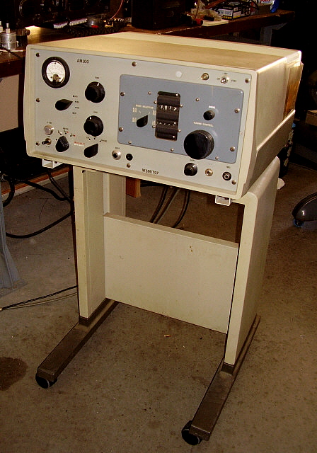
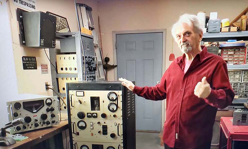
"1625 Rig" Follow up Five Years after Purchase - 2023 - 
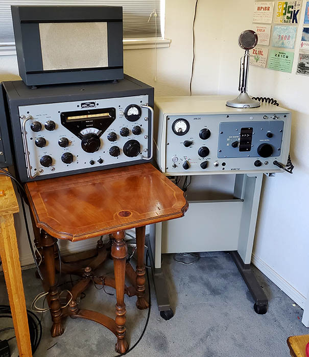
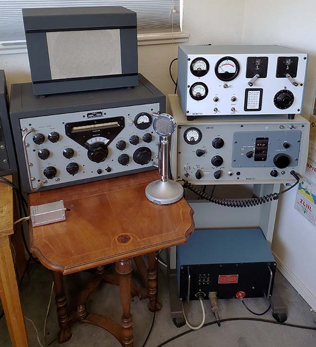
For the past four years I've had the "1625 Rig" in the upstairs ham shack. Most of that time it was operating using a 135' CF Tuned Inv-Vee antenna. That antenna was destroyed in a winter storm at the end of 2022. For the past five months, the "1625 Rig" has been operating on the 75M Collinear Array antenna which should exhibit a slight bit of gain (about +1.9db is possible.) The audio quality is instantly recognized 
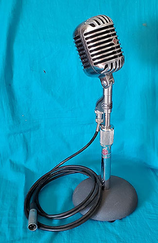
whenever I'm operating the "1625 Rig" and I only use a D-104 on a TUG-8 stand with a PL-68 plug as the audio input. At borderline QRP-level 70 watts of carrier power, as expected, conditions play an important part in successful communications. Using the "1625 Rig" in the winter is generally without any problems since propagation is excellent at that time of the year. Summer conditions will always present a challenge. It does depend a lot on the receiving station's QTH and their local noise level. On my end, the receiving noise level is about S-2 or less (I always hear everybody on the net, regardless of the time of year.) But, using a 70W AM transmitter and trying to have my skywave propagated signal overcome the receiving station's local S-9+ noise level is difficult no matter what time of the year it is or what type of antenna I use.

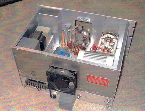
The Noisy Fan - One change I've been wanting to make to the 1625 Rig is to replace the fan that is mounted behind the PA/Modulator box with another type of fan that would be quieter when running. This fan is extremely loud making the transmitter sound something like a vacuum cleaner when it's in operation. The 1625 Rig has two fans but the one for keeping the power transformer cool is a very quiet 120mm "muffin" fan. The second cooling fan is the noisy one because of how and where it's mounted along with a blade design that creates more noise than air flow.

In looking at how the PA/MOD fan mounts, the open frame motor is on the inside of the PA/MOD box. Then the shaft protrudes though a purf-metal (.190" diameter holes) rear panel and the fan blade is mounted external to the purf-metal rear panel. The fan is mounted so that it draws air from the front of the PA/MOD box then through the box and exhausts hot air out back. The PA/MOD box has a purf-metal front panel to allow air in. There is another purf-metal divider between the PA and the MOD sections. Since there are three purf-metal panels, maximizing air flow volume wasn't an issue and apparently a minimal air flow will keep the 1625 tubes cool (this is the only transmitter I've seen where the 1625 tubes are actually "cooled.") I can use a "low noise" type of muffin fan to replace the old external four blade fan. I'll have to remove the transmitter rear panel and the rear sheet metal piece on the PA/MOD chassis. I'll remove the motor mount that is on the chassis inside the PA/MOD box and then the new muffin fan will mount to the exterior of the rear panel of the PA/MOD box. I might enlarge the shaft hole in the rear purf-metal panel to 4" for better fan performance and reduced noise (no purf-metal directly behind the fan blades.) These fans can be mounted with rubber bushings to reduce vibration. Usually the modern muffin fans are very well balanced and don't produce any vibration. Just the opposite is true of a open frame motor with a long shaft and removable fan blades. Vibration is dependent on the rotational dynamic balance of the rotor inside the motor and on the position of the fan blade on the shaft (and normally the fan blades aren't dynamically balanced either.) So, these open frame types of fans always seem to vibrate excessively. The variables are all removed when using a muffin fan so balance is always excellent and vibrations almost non-existent. The AC Infinity Type 1238 runs at 1800RPM and moves 62cfm of air and has a noise rating of 32db (just above a whisper.) The Type 1238 physically the same size as the muffin fan installed to cool the power transformer at 120mm. If the Type 1238 is mounted to the rear panel of the transmitter there will be a symmetrical appearance of the two fans that should look like it was planned that way. Ordered the Type 1238 on August 7, 2023.

Clean Up - Aug 7, 2023 - I removed the top cover and also the top cover on the PA/MOD box to inspect the fan mounting. It looks like I'll have to pull the PA/MOD box to do the actual fan removal and installation of the new fan. In looking over the modules, I noticed how dusty everything was. I haven't had the top cover off of the 1625 Rig since 2018 and looking at the photos I took of the chassis then it doesn't look that dusty but I know all this dust didn't accumulate in the past five years (well, maybe some of it.) At any rate, I'll have to clean up everything while doing this fan upgrade. While I'm at it, I'll test all of the tubes,....something I didn't do when I first got the 1625 Rig since it had come almost directly from W6MIT and he had been using it regularly on the 40M AM net. So, this reworking will be the fan upgrade plus a service and detailed cleaning.

Removed Exciter and Removed PA/MOD box - Since the design is modular, removing these two modules was easy. The Exciter was very dusty. Even the mechanical digital (Veeder-Root type) readouts were dusty and the inside of the plexiglass window was dusty. Detailed cleaning and lubrication required Exciter front panel removal. The band change mask articulation was gummed up and sticking which required cleaning and lubrication. Even then, I had to shorten the return spring about .375" to increase the return tension to get the mask to change position without dragging slowly. The plexiglass needed cleaning and the front panel also needed cleaning and buffing to have it looking like a nice condition T-368 Exciter. Knobs needed cleaning, especially the flutes. Soaked in warm soapy water for a half an hour then brushed to remove the finger gunk from the flutes. I had to replace the band switch pointer knob because of some sort of white deposits that wouldn't clean off. End result,...it's the best this Exciter has looked in a while. 

I removed the back purf-metal piece on the PA/MOD box. This allowed easy access to remove the fan motor and mounting bracket. There are two insulated stand-offs for 120vac to the fan, so the new fan power cord can connect there. I removed the fan-mounting bracket since the muffin fan will be mounted directly on the rear purf-metal panel. Cleaned inside the PA/MOD box. Light dirt is all. Cleaned up nicely. I enlarged the shaft hole in the purf-metal rear cover to 4" to allow unrestricted air flow out of the PA/MOD box.


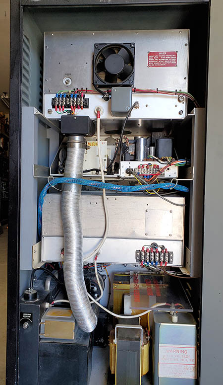
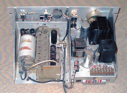
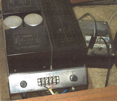
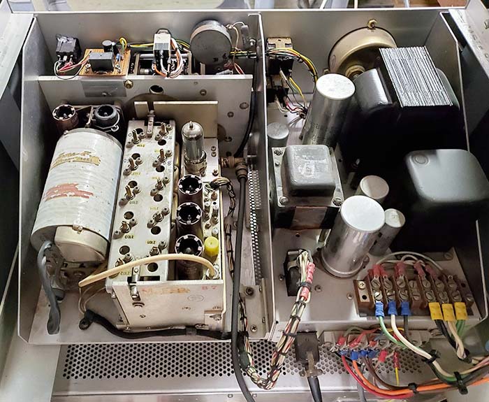
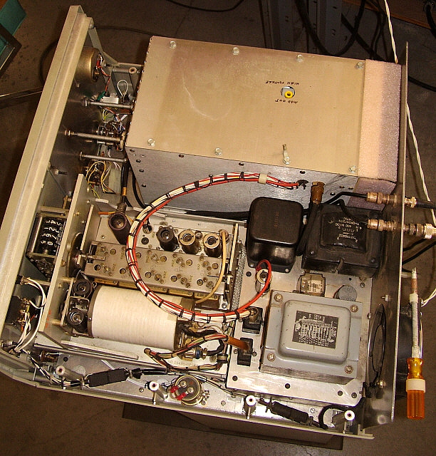
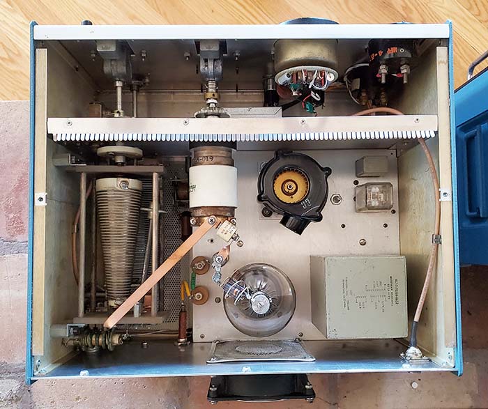
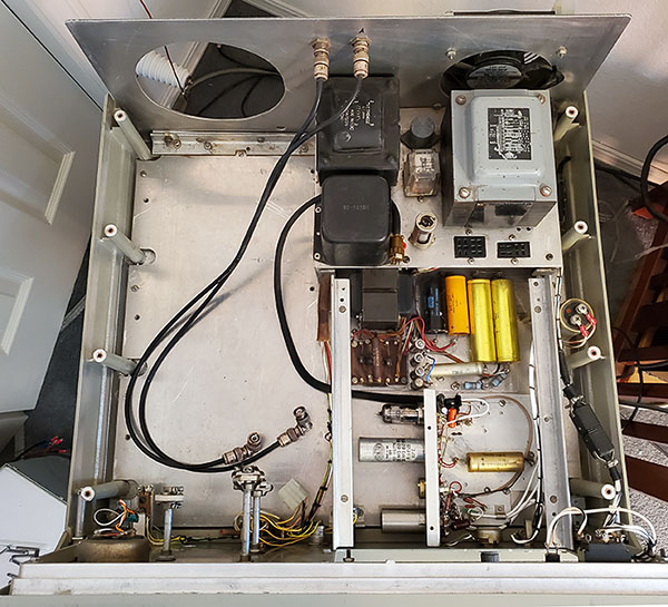
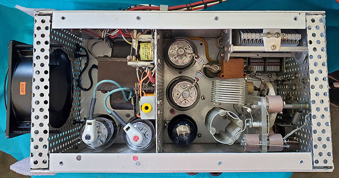
Photo Left - The 1625 Rig with PA/MOD box removed (on the left) and the T-368 Exciter removed (on the right.) Removal of the Exciter reveals the Speech Amplifier that's located underneath. The front section of the power supply is also revealed when 
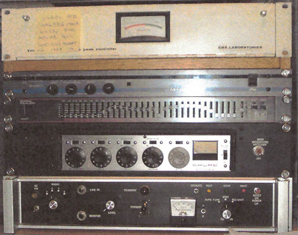
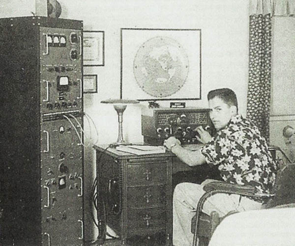
the Exciter is removed. Note how W6MIT's 2007 upgrade leaves only two tubes in the Speech Amp and also that most of the original components were replaced (compare to W6MIT's 1997 photo above.) The chassis mounted power supply transformers and chokes provide the +HV at +800vdc and the screen voltage supply at +350vdc for the 1625 tubes. Additionally, the 12.6vac and 6.3vac filament voltages and the -30vdc bias supply are supplied by the transformer windings. Note that the two chokes on the left side of chassis are much larger than the pre-2007 chokes. The 0A2 regulator is for the Exciter PTO.

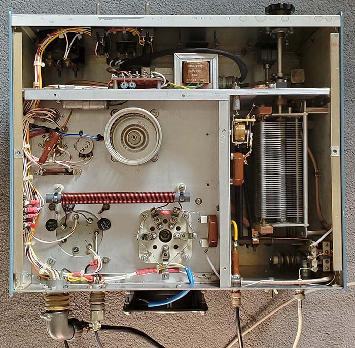
Note that the T-368 Exciter sets on rails in the transmitter and that allows easy removal of the unit. The PA/MOD box mounts to the aluminum bottom plate and is entirely connected into the circuit with wire cables/connectors or with coaxial cables for the Ant output, the Receiver input and the Exciter output to PA input. Also, note this photo shows the rear panel fan hole as circular. It was modified to be a square opening for the new fan placement in 2023.
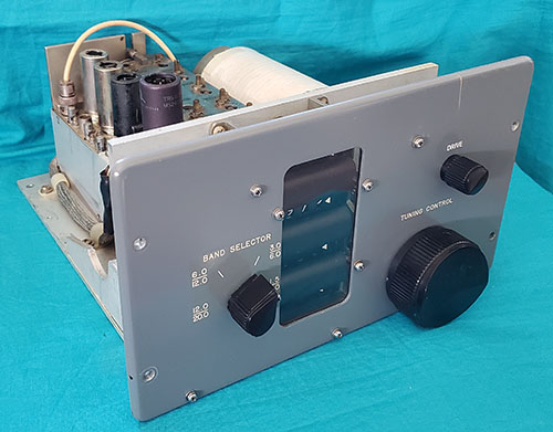
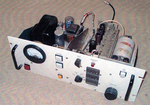
 

The T-368 Exciter after clean-up. I had to replace the band switch knob with a good condition original. The digital display and masks required "front panel off" cleaning and adjustment.

Tube Testing Had Interesting Results - I didn't test the tubes in the "1625 Rig" when I first got it since it seemed to work as described in MIT-John's manual. So, after five years it's about time that the tubes were tested. The results seem to confirm that perhaps I should have tested the tubes sooner. I used my old TV-7B for testing.

1625 - 4 tubes - I replaced three of the four 1625 tubes. One modulator tube was weak (well below minimum acceptable) and one PA tube was weak (also below min.) I selected replacements from my NOS stock that seemed to match up pretty well.

6Y6G - 1 tube - This tube tested strange but I tested a few other NOS examples and they all do essentially the same thing. That is a fast large upward swing of the meter, then a fast dropping down to zero and then a slow rise to something above minimum acceptable. I replaced the original 6Y6G because it didn't rise up to minimum. The third tube tested (NOS ones) seemed to perform correctly rising well above minimum, so it was installed.

12AX7 - 1 tube - As expected this tube tested very weak (way below minimum acceptable) on one triode and just at minimum on the other triode. I installed a good 12AX7.

12BY7 - 1 tube - This tube tested very weak, way below minimum. I installed a NOS 12BY7.

6AH6 - 3 tubes - Two of the three tubes tested okay. I had to replace one as it tested at minimum acceptable.

5749/6BA6 - 2 tubes - PTO tubes tested good.

5763 - 1 tube - Tested good

0A2 - 3 tubes - All three tested good

So, in total seven tubes were replaced out of the 16 tubes used in the transmitter. The 1625 Rig did work and, other than complaints about my lack of signal strength, none of the "on the air" contacts ever mentioned anything else (maybe because of the "weak signal".) Most tube-based devices will seem to function okay with weak tubes. Really bad tubes,...that is, those that have open filaments, hard shorts, etc., of course, those won't work. But, weak tubes will perform okay,...but just okay,...not great. So, I'm not expecting a big change and maybe not anything even noticeable. I just like to have a transmitter or receiver equipped with all "tested-good" tubes installed. So, this might be the first time that I'll experience using the 1625 Rig in that condition. One of the first things noticed was the increase to 75 watts of AM carrier output power with 150mA of pI.

New Fan Installation - Due to the depth of the muffin fan at 1.5" thick, it can't be mounted inside the PA/MOD box as there is only about .75" clearance from the rear panel to one of the 1625 modulator tubes. Mounted on the outside of the purf-metal rear panel only .75" of clearance was available between the back of the PA/MOD box and the rear panel of the transmitter unless the rear panel opening is modified. I think the mounting of the fan to the rear of the PA/MOD box with a 4" diameter opening, eliminating the purf-metal obstructions, will result in the best air flow and cooling. Testing the fan mounted to the purf-metal rear panel resulted in quiet operation and lots of air being drawn through the box. I removed the transmitter rear panel for measurements to modify the old oval-shaped opening. I decided that if I went with a square opening, fitting the PA/MOD box with the rear mounted fan into the transmitter would be easier since there would be lots of clearance for positioning the box with no interference with the rear panel opening. The square opening is about .75" larger all around the square fan perimeter with the opening being about 6" square. The easiest method to enlarge and reshape the rear panel opening was to use a jig saw. Afterwards only minor touch-up with a file was necessary to have the four sides square (see photo below.) 
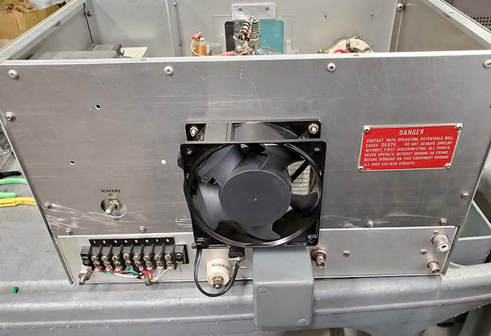
As for power to the fan, the fan itself has a plug-in cord with receptacle. The fan AC cord was routed through a grommet-hole and soldered to the insulated stand-offs that the original fan had used.


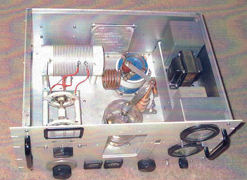
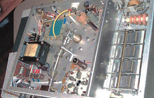
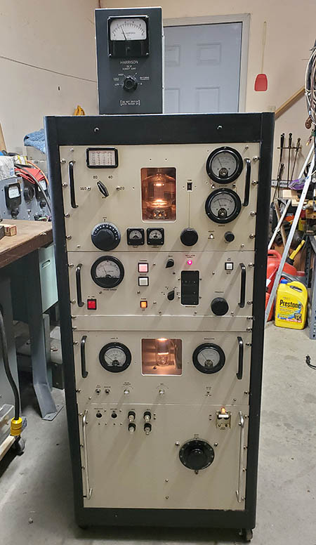
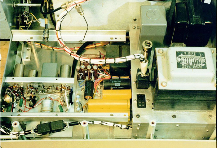
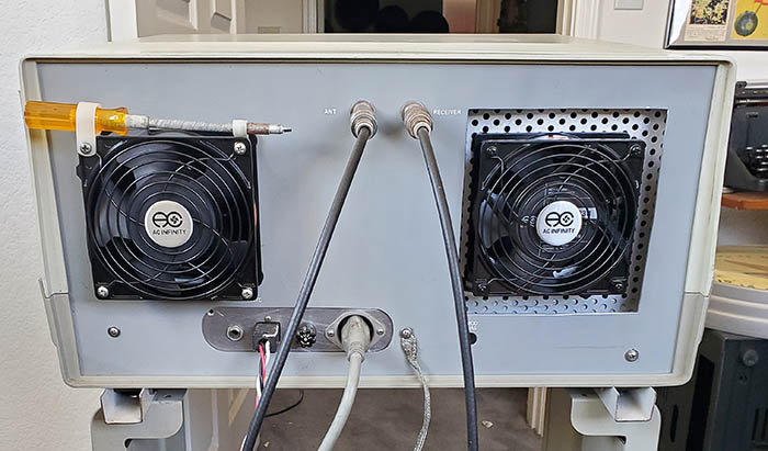
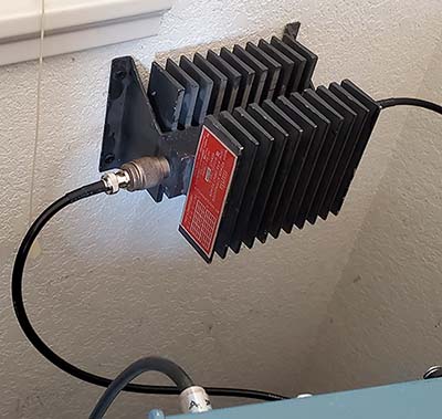
photo right: PA/MOD box showing the modification for the new fan mounting for reduced noise and improved air flow

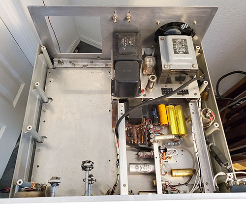
I think this arrangement will cool the 1625 tubes much better than before. The original fan installation had the blades outside of the purf-metal holes forcing the fan to draw the air entirely though .190" diameter purf holes located in three separate panels. Now the fan mounting is entirely open (as can be seen in the photo above) and pulls air just through the purf-holes in the front of the box and through the divider purf-holes. To test the air flow, I used a 2"x 2" piece of paper towel and with the fan in operation the piece of paper towel was pulled on to and would "stick" to the purf-holes in the front of the PA/MOD box. The transmitter cabinet air flow arrangement is the 120mm fan by the power transformer pushes cool air into the transmitter cabinet then the PA/MOD box 120mm fan pulls that air through the box and exhausts the warmed air out the back of the transmitter.

The final benefit is the fan noise has easily been cut in half, maybe more. The combined fan noise was somewhat over 60db before because you had to raise your voice to talk over it. The noise is much less now but the new AC Infinity Type 1238 is so quiet that the noise from the old Radio Shack fan that blows on the transformer sounds relatively loud now. I unplugged the Radio Shack fan and listened with just the Type 1238 on, very quiet indeed. The old frame motor fan and external blade was so loud, I couldn't really hear that the Radio Shack muffin fan was also fairly loud. Replace? It can easily be accomplished.


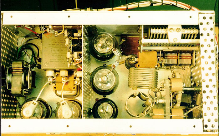
photo left: Showing the new square opening for the new PA/MOD box cooling fan

Reassembly and Testing Reveals a Problem - Aug 12, 2023 - The Meter Switch has too many positions making it difficult to tell where to set the knob. I just switched until I saw 10mA of Grid current that was adjustable with the Drive control. This would be the "G" position reading PA Grid current. Although the Exciter is putting out sufficient grid drive, I don't get any PA plate current at all. Also, it appears the the LOAD condenser has some rubbing plates. The LOAD condenser is so well protected, I know I didn't have anything get inside the PA/MOD box that would have bent any plates. I can't see anything obvious but I can hear the scraping sound at about 40% unmeshed. All other areas of rotation are okay.

I pulled the PA/MOD box (again) and then pulled the top and pulled the Pi-Network (two screws and two plugs, easily accomplished.) This allowed isolating the LOAD condenser to see if it really was rubbing. I had to hold the T/R relay closed and I did measure that a short was happening. The problem was in the front-most gang and was caused by minor plate bending. The short was only happening in about <5 degrees of rotation with the other ~175 degrees being fine. This may have been the condition of the this three gang (500pf max per gang) air variable for some time. I've only operated the transmitter on 75 meters and then only on 3974kc, so the LOAD hasn't changed position while I've operated the transmitter. At any rate, I worked with the two front-most plates of the front gang and got the rubbing cleared and the short was gone.

I checked the PA/MOD box over very carefully. I found an unsoldered bypass cap on one of the PA tube sockets. No other problems found. I reassembled the Pi-Network and reinstalled the 1625 PA tubes and the 6Y6G Clamp tube.  >>>

>>>  I pulled the Exciter (again) and checked the speech amp and power supply that are covered when the Exciter is installed. Nothing found.

I reassembled the transmitter and this time it worked flawlessly with 75 watts output power with 150mA of Ip. I don't know what was causing the initial problem. It seems unlikely that it was the LOAD control. Maybe I had the A and R coax cables on the wrong BNCs but I had everything marked so that seems unlikely. I tested the audio and how the 'scope pattern looked. I noticed I had to slightly increase the audio gain, probably because the carrier wave is somewhat larger now (actually, it was a weak battery in the TUG-8 stand.) Next is a new location for the 1625 Rig and a new receiver partner.

1625 Rig Typical AM Readings - PA Ip = 150mA,  PA Ig = 10mA (adjust Drive for 10mA) 

MOD Ip Idle = 45mA   MOD Voice Peaks = ~125mA

RF Pwr Out 50Z = 75 watts carrier power only

PA/MOD   Vp = +750vdc   Vs = +300vdc (regulated)


The 1625 Rig Gets Two New Fans - Cool!
The fan on the left pushes cool air in while the fan on the right exhausts hot air out.

Another AC Infinity 1238 Fan -  Second AC Infinity Type 1238 fan ordered August 14, 2023. New fan arrived Aug 17th. The installation could be accomplished without removing any of the modules. I did have to dismount the rear panel but it's only secured by three screws if the top of the cabinet is removed. The new fan had the same plug-in AC connector on the side of the fan. Since the fan is mounted on the exterior, I had to drill a hole (.312" dia) for the AC cable to enter the transmitter interior. I installed a rubber grommet in this hole. I also had to remove the two-pin Cinch-Jones plug from the old fan cable and install it on the new fan's cable. I couldn't use the metric screws provided for mounting the fan because of the plastic cable clamps that are used as holders for the flex screwdriver. All holes aligned perfectly since this new fan was exactly the same size as the old fan. I installed the top cover and reconnected all of the external cables. A quick test and everything worked fine (78 watts of carrier power at 150mA Ip.)

As for noise, I think the new fan is very close to the old Radio Shack fan as far as noise produced. The difference is in the air flow through the transmitter. A piece of paper will be pulled against the intake fan grille and it's blown away by the exhaust fan. I let the transmitter run for about 15 minutes and for several minutes I was doing some RF power testing and tuning. After I had finished testing I thought about feeling the exhaust air and it was noticeably warm. That wouldn't have been the case with the old fan set up. I think the new fans are keeping the transmitter interior much cooler than before and, for the amount of air being moved, the 1625 Rig is amazingly quiet. What little fan noise is present is completely masked if the receiver is in operation with just the normal "no signal" background noise being received. 

The photo left shows the rear of the 1625 Rig with both of the new fans installed. I had to make the square hole somewhat larger than the fan body to allow easy installation of the PA/MOD box with the rear panel installed or to allow easy removal of the rear panel with the PA/MOD box installed. Also, there was dealing with the remains of the round hole max diameter vs having an actually "square hole." Even at that, at the center of each side of the square hole a slight dip can be seen. I was trying to keep the square hole size to a minimum.

The New Set-up for the 1625 Rig - I was continuing to have odd, intermittent parasitic oscillation problems when running the KWS-1 on AM. It seemed like I'd fix the parasitic problem only to have it reappear in a week or two. After owning this transmitter for 52 years, it's probably time to thoroughly go through it,...but that's another article for another time. But, moving the KWS-1 was necessary because that was where I wanted the 1625 Rig to be placed. This location would allow easy observation of the signal monitoring oscilloscope and DFC. Also, cables to the Johnson Matchbox would be much shorter. This had actually been where I had the 1625 Rig about a year ago, so now it's back in the corner again.

The 1625 Rig's new receiver mate is the Collins Laboratory 51J-4 with the light-gray front panel. I've had the light-gray panel 51J-4 for about a year now. It has a Collins-installed RC coupler in place of the 6kc mechanical filter that results in very nice communications-grade AM audio. When I got the receiver it barely picked up anything. One of the IF amplifier tubes was a 12BA6 instead of a 6BA6. All of the tubes tested good after I replaced the 12BA6 with the correct 6BA6. I performed an alignment that just confirmed that the receiver had been aligned already, recently. The 12volt heater tube was causing all of the sensitivity problems. I found an original 51J-4 cabinet to install the receiver into. Break-in on 51J-4 receivers requires an external 18vdc power supply (at 200mA) to actuate the break-in relay inside the receiver. I use a very small homebrew PS in a little aluminum project box. The 1625 Rig provides the T/R contacts to turn the break-in PS on to put the 51J-4 into stand by. The loudspeaker is an old 270G-3 I've had for over 50 years (that's why it still has its cream color flocking.) The 51J-4's performance now is quite good and should work well with the 1625 Rig.

Although the 1625 Rig is ready to go now in late-August 2023, I'll probably wait a few more weeks until mid-September to give the transmitter its debut after its servicing, new tubes and minor modifications. Even though the output power is slightly increased with the new 1625 tubes, 75 watts of carrier power is still border-line QRP and I have to wait for the improvement in propagation that begins in mid-September. I'll be using the 234' Collinear Array antenna and that should help with a little over +1db of gain on 75M.

UPDATE: Aug 20,2023 - Conditions were so good today I decided to go ahead and use the 1625 Rig on the mil-rad net. All reports were complimentary with the most common observation made being "sounds as good as it always did." In other words, not much difference noted in the tube upgrade or the slightly increased power output. Not unexpected since most of the improvements would be pretty subtle on the receiving end. What I noticed was how quiet operation is now. I literally cannot hear the two fans in operation when the receiver is at normal listening levels and receiving signals. If I lean over or get up out of the chair so that I have a different listening angle, then I can slightly hear the fans but they aren't loud. The nice part is when sitting in front of the receiver, I don't hear the 1625 Rig cooling fans at all. Also, many times during the one hour net, I would feel the exhaust fan air to see if the air coming out was hot. I think the fans are keeping the transmitter interior cool because the exhaust fan air was only slightly warm. So, nice improvement.


A Long History of Homebrewing
 

W6MIT Homebrew in 1951 - Here's a B&W photo of an early W6MIT homebrew transmitter. The year was 1951 and MIT-John was 15 years old at the time. He built the transmitter using several BC-375 TUs and other surplus parts. The transmitter uses a 6AG7 oscillator, a 6L6 buffer and an 813 PA that was later changed to a 4-125 tube. The frequency was changed using plug-in coils. The modulator used the 600Z patch panel on the transmitter to run balanced audio with PP 6L6s driving PP 811A tubes. The HV power supply used 866 Hg vapor rectifiers. John's receiver was a Hallicrafters SX-71. According to John, he was working ten meter phone a lot at the time because the sunspot cycle had propagation "blazing hot."


photo left from: Electric Radio (although I had to "Photoshop" it a lot.)

W6MIT QSL Card ca: 2010

John's QSL card shows some of the audio chain for "The Big Rig" including the Carvin 87-S mike, the desk top remote, the Shure mixer, the Ross equalizer and the Apex Compeller processor. A cassette tape deck is on top of the audio gear. The R-390A on the left has John's homebrew modulation monitor on top. Just visible on the right is his National NC-183D receiver.


Return to Home Index


Radio Boulevard
Western Historic Radio Museum

 Vintage Radio Communication Equipment Rebuilding & Restoration Articles,

 Vintage Radio History and WHRM Radio Photo Galleries

1909 - 1969

- 60 years of Radio Technology -


This website created and maintained by: Henry Rogers - Radio Boulevard, Western Historic Radio Museum © 1997/2024