|
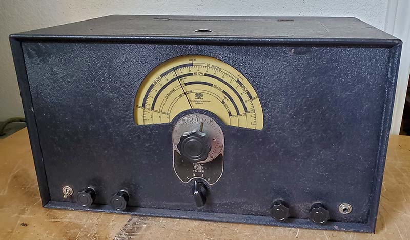
No Receiver is Perfect
The Solution for IF Overloading with AVC Off
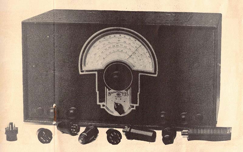
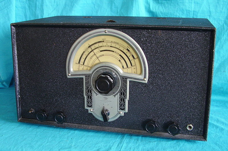
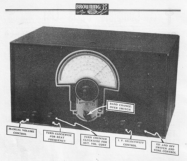
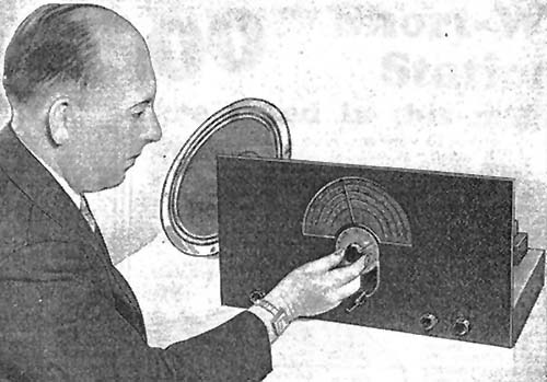
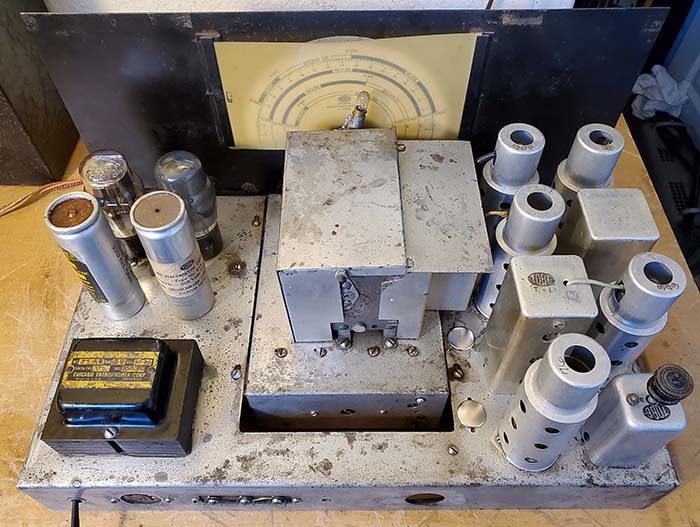
The Problem - The TOBE
receivers have a difficult time when tuning into MODERN
powerful ham signals in the SSB mode when using a large,
resonant antenna. One does have to consider that these receivers were designed in the mid-1930s
when noise levels were low, most ham transmitters were running
CW at
less than 100 watts and most receiving antennas were simple
50 foot long end-fed
wires (remember, the Browning design is almost 90 years old!) Also, one has to consider that
these receivers were kits that had to be fairly easy to build
and the selling price had to be kept reasonable. The original
Browning 35 design was for a short wave receiver that primarily
was for AM reception. When the TOBE receivers are
operated in the AM mode, which forces the use of the AVC control
circuits, modern AM reception is great. The RF amplifier and the IF
amplifier grids are BOTH biased with the AVC voltage that is
inversely proportional to the signal level, that is, as the
signal level increases the AVC bias voltage becomes more
negative. The end result is no
distortion regardless of the level of signal input. BUT, the ham
receivers were almost certainly used primarily in the CW mode (in
the thirties, CW was the dominate mode of ham communication.)
CW reception requires the BFO to be turned on and the AVC to be
turned off. In this set up, the RF amplifier stage runs at
maximum gain and the IF amplifier gain is only controlled
by the variable cathode resistance to chassis-ground, a self-bias type of
control. The level of
apparent grid bias available at the IF amplifier tube is not
capable of controlling the receiver gain when tuning modern CW/SSB ham
signals AND there's no way to
throttle-back the RF amplifier gain that's running at maximum.
The result is extreme distortion on SSB signals due to
signal overload in the IF stage, even with the IF gain set to
minimum. Browning seems to have been aware (from his 1930s
perspective)
of this potential problem, although in the 1930s, CW signal levels
were not nearly as potent then and, MORE IMPORTANTLY, high-power SSB was far in the future.
When in the CW mode, signal overload might have only happened occasionally back then.
Browning did change the IF gain control from 10K
up to 20K to provide better IF gain control (possibly only for the ham
receivers.) For modern CW signals, the distortion isn't nearly
as noticeable due to the nature of the signal (being a keyed
tone) and, additionally, almost all modern CW seems to be at a
power level of about 100 watts or less. Only powerful SSB
signals, of which there seems an abundance, are difficult to
demodulate without distortion.
Possible Solutions
- As an
experiment to confirm my analysis of the problem, I disconnected
the 400 cathode resistor in the RF amplifier circuit and "tack
soldered in" an adjustable 25K rheostat instead. With control over
the RF amplifier gain I was able to easily find a balance of RF gain, IF
gain and Volume (AF gain) that would provide undistorted demodulation of
extremely strong SSB signals when using a resonant large antenna
(tuned collinear array.) I didn't encounter ANY powerful
SSB signal on either 40M or 20M that couldn't be demodulated
with a combination of RF gain, IF gain and the Volume control.
Now, I'm certainly NOT
advocating that this mod be done to any TOBE receiver. My
installation was only a temporary one and it was just done to
confirm my analysis regarding the "fixed-at-maximum gain" RF amplifier
being "the problem" when in the CW (and modern SSB) mode. As stated, if the
receiver is in AVC for the AM mode, the AVC bias controls both
the RF and the IF gain and reception is excellent for all levels
of AM signals - BUT not in the CW mode with the AVC-off
and with a manual gain control that only functions on the IF
amplifier tube and, most importantly, with the RF amplifier
running at a non-adjustable "maximum gain."
Easy, All External, No Mods Solution
- For an
absolutely "no mods" solution, the easiest method
is to be able to control the RF level from the antenna tuner to the receiver
antenna input. Using a "tuned
antenna" set up will allow using the antenna tuner itself as an
attenuator to reduce the level of signal as needed. When maximum
sensitivity can be utilized, then the antenna system can be "in
tune" for best response. And, by a mere adjustment of the tuner, the operator can
reduce the RF level by "detuning" the antenna to cope
with extremely strong signals. A popular device at one time was
the receive-only antenna coupler. This was a small antenna tuner
that allowed adjusting the match of the station antenna to the
receiver only. It could enhance the signal or it could also be
used as an attenuator for strong local signals. This antenna
coupling device method will work most of the
time but extremely powerful SSB signals may still distort.
Also, in a working vintage ham station, it normally does require a
DPDT frame-type relay to switch the balanced feed line from the
transmitting coupler to the receiver coupler. However, for the
vintage approach, the receiver antenna coupler was the method
used by many hams.
Another less-complicated method is to use a simple adjustable voltage
attenuator can be inserted between the receiver antenna input and the antenna
or antenna coupler output.
The attenuator would allow using the maximum antenna response
when weak signals are to be received
and a reduction of the RF level when extremely strong signals
are encountered. Suitable attenuators are fairly cheap at about
$25 and provide stepped attenuation from 0db up to -82db using a 50 ohm
load. They are from China and can only handle 0.25W so they are
definitely for "receive only" use. They have a nice
layout, a small metal housing and the attenuator adjustment by multiple toggle
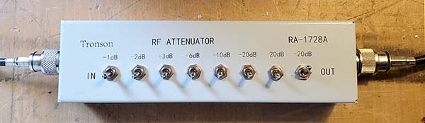
switches and input/output via SO-239 connectors.
Testing with the Tronson Attenuator Between
the Collinear Array/Matchbox Output and the TOBE SPECIAL Antenna
Input - I bought the Tronson RA-1728A attenuator off of
eBay. I had to pay about $10 more to purchase from a USA-based
seller ($35 with free shipping.) The SO-239 input and output connectors make hook-up
easy. The Collinear Array is the largest antenna I have at 240'
center-fed with 106' of open feed line. There is a slight gain
of a little over +1.5db on 75M and a little more than that on 40M
and 20M. The received signals when using this antenna are
noticeably stronger than with the 130' Tuned Inv-vee antenna. The
attenuator was tested on 80M, 40M and 20M. ALL extremely
strong SSB signals could be easily reduced in strength just by
switching the labeled toggle switches. For example, -20db + -20db
+ -3db would equal -43db of attenuation. The switches allow
selecting any level between 0db and -82db in -1db increments. You
have to add up the total of the db switches thrown to know how
much attenuation is switched in. Most strong SSB signals on 80M
required about -40db of attenuation. One really strong SSB
station required -70db (must have been a local.) On 40M, between
-40db and -20db was typical. On 20M, between 0db and -10db was
typical. The Tronson RF Attenuator is shown in the photo below.
| I couldn't find ANY SSB station
strong enough that the attenuator couldn't reduce the signal
level to where the TOBE SPECIAL easily demodulated the SSB. For
weak signals, the attenuator can easily be switched out of the
circuit by placing all of the toggle switches to the "down"
position. Using the attenuator allows keeping the
antenna resonant (tuned for the received frequency) and
just reducing the signal level of extremely strong
stations as needed BUT
still having the ability to easily return the antenna system/feed
line to maximum response for weak signals. Another observation
was that by
reducing the input signal level before the RF amplifier, it
seems there's much less distortion than with the simple RF
amplifier cathode-type gain rheostat modification. The antenna attenuator is
by far the easiest
and best method to deal with the IF
overloading of the TOBE SPECIAL (and the ACR-35H) when used with
a very large array antenna. |
 |
|