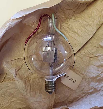
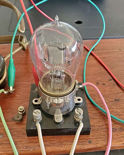
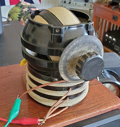
Radio Boulevard
Western Historic Radio Museum
 

Spherical Audion Receiver
ca: 1915 to 1917

~ Profiling a pre-WWI 'Panel Set' Receiver ~

Circuit and Construction Details
Function of Controls
1988 Restoration and Testing
Profile of 1910 DeForest Spherical Audion
1989 Antique Radio Classified Article
2022 Refurbishment and Testing
2022 External Component 'No Mods' Regeneration
2022 External Component 'No Mods' Audio Amplification
Addendum - Testing the Mudock No. 344 with vacuum tube detector


by: Henry Rogers WA7YBS


Hiram Percy Maxim at his station in 1915
Note the Loose Coupler and Spherical Audion Detector
With head down, Clarence Tuska is busy with copy - from the ARRL website

This QSL was a surprise to find in a large box of unsorted old QSLs sent to me by NU6AM. The card is postmarked OCT 17, 1921. It was sent to Ed Glaser 2BRB in Brooklyn, NY. Of course, the card was sent by 1AW Hiram Percy Maxim confirming that 2BRB was entered in the log at 1AW in Hartford, Conn. "Schnell" is the type of receiver circuit 1AW was using. Too bad a stamp collector thought that the 1 cent stamp was more valuable than the card.

I've owned this Spherical Audion Receiver for over 34 years. I wrote an article for Antique Radio Classified about this receiver that was published in 1989 but, other than that brief write-up, I've never really detailed this receiver's history, its construction or its performance. In fact, the last time I operated this receiver was in 1989. It was in my collection in Minden, Nevada from 1988 up to 1993. Then I had it on display at the Western Historic Radio Museum in Virginia City, Nevada from 1994 up to 2012. For the past 10 years, it's been on display in my study in Dayton, Nevada. So, after 30+ years of just setting around, it's time for a really comprehensive look at this very old and very rare receiver.

Spherical Audion Receiver - ca: 1915 to 1917

The builder of this wonderful Spherical Audion Receiver is unknown. The quality of workmanship, including the stamped number nomenclature and etched scales on the front panel along with some of the clever mechanical features, seem to indicate a professional-level of design and construction. But, does that imply a special-build product of an unknown commercial outfit? Of course, there were also some incredibly talented amateurs that were fully capable of building this receiver. Dating is just speculation,...

Build Date and Users - Dating the Audion Receiver to between 1915 and 1917 was arrived at by noting that the circuit is non-regenerative. Although DeForest and Armstrong both claimed the regenerative detector invention in 1912, Armstrong was initially awarded the patent in 1914. The first commercially-built regenerative receiver was the Paragon RA-6 from 1916 but, as a counter-argument that all receivers built after 1916 used regeneration one only has to look at the WWI SCR-59 use of a non-regenerative detector (with two audio amplifiers) and most SCR-59s were built in 1918. Another indicator would be the "dead-turns" (unused sections of tapped inductors) are not grounded and that can cause losses due to stray coupling. "Dead-turns" were normally grounded after about 1917. Then there's the Spherical Audion tube itself. Although DeForest first patented the triode in 1906, it took him some time to be able to commercially manufacture them. The earliest Audions had tubular envelopes. The Spherical Audion tube was a bit later as the glass manufacturer (McCandless) suggested the spherical blub shape would be easier to produce. The Spherical Audion started to be produced in 1908. DeForest came out with the RJ-4 Audion Control Box in 1910 but was still making changes in the Audion up past 1912. Most importantly, DeForest did have a contract with the Signal Corps during WWI to supply them with Spherical Audion tubes, meaning that even in 1917, it was a tube that was still being used. DeForest ended up not being able to meet specifications and eventually the contract went to GE.  >>>


The Spherical Audion Receiver - 2022 photograph


Behind the Panel of the Spherical Audion Receiver
Not too many components required. The Loose Coupler and Bell Crank take up most of the Redwood base board. The Antenna Condenser is upper right and the Secondary Condenser is upper left. The small rectangular component in the center of the panel is the grid leak condenser. The E.I.Co. rheostat is very apparent. The wiring harness for the secondary coil is rubber insulated for flexibility. Buss wire is sleeved.

>>>  After researching several "dated" vintage photographs to see when certain design characteristics were being incorporated into ham station receivers I've concluded that the Spherical Audion Receiver is most likely an amateur-built wireless set dating from 1915 to 1917. If it had been professionally-built, one would think that a company or an individual professional builder would have put a name on the receiver. Use of the DeForest Audion tube also tends to point toward amateur construction. Based on the overall design and its clever use of mechanical devices along with its use of a Spherical Audion tube and the fact that it's a "panel set" type of receiver, it's my belief that this receiver was built between 1915 and 1917 - probably by a very talented amateur.

Circuit and Construction Description - The circuit uses a Loose Coupler tuner and a non-regenerative, grid-leak detector. On the lower right side of the panel is an interesting dual control the outer knob of which varies the secondary inductance coupling via a bell crank while the inner knob selects the secondary turns. Another clever control is the large antenna tuning series condenser on the upper left side of the panel. If the knob is rotated to either end of its scale and the metal pointer put into contact with either of the stop pins, the condenser is then shorted (rotor to stator) and essentially taken out of the circuit. The back-up crystal detector appears to have been a somewhat later addition since the quality of workmanship doesn't match that of the original construction (that later date is probably 1919 to 1922 since the detector is galena, a mineral that didn't become a popular detector until after WWI.) A crystal detector was a common addition to early vacuum tube receivers as it allowed the receiver to still be used if batteries were depleted or if the tube or tubes failed.

The cabinet is solid mahogany that has been stained a medium red color. The internally mounted base that the loose coupler and bell crank are mounted on is made out of Redwood. The use of Redwood implies that the receiver was probably built somewhere on the west coast (probably California.) The front panel is .75" thick hard rubber that has nomenclature that is a combination of stamped numbers and scribed scales. The nomenclature is filled with white paint.

Panel Sets and 1989 Testing - These types of receivers that have all of the components adjustable from the front panel and with all of the components within a cabinet were called "Panel Sets" before WWI. That was to distinguish them from the then-popular receivers that were constructed by interconnecting a maze of individual components setting on a table.

My initial testing (33 years ago) concluded that signals picked up on this receiver were either weak or inaudible (well, it is basically a crystal set!) Regeneration would have been a big help. The receiver was tested using several different kinds of detector tubes by way of a homemade adaptor back in 1989. The best performance using "vintage tubes" then was a Moorhead ER type tube, though these are post-WWI (1919) tubes. I found then that the ER sensitivity was just slightly better than a modern germanium diode. 

It seems that after 33 years, it might be time for "retesting" to see how the Spherical Audion Receiver performs with a little more attention to the types of tests and actual measurements using test equipment. Also, I've been thinking about adding an "outboard" regeneration circuit that doesn't modify the receiver and just connects to the receiver using already existing terminal binding posts.

IMPORTANT NOTE: The 2022 testing has had very different performance results with dramatic performance improvement from those tests performed 33 years ago. The new test results completely changed my opinion of vacuum tube detectors in a non-regenerative configuration. The testing is covered in detail in the "Refurbishment and Performance Testing - 2022" section further down this page.


2005 photo


A Different View Shows the Minimal Cabinet Depth

Receiver Controls and Components - The left side (as viewed from the front) of the receiver is the Antenna Tuning circuit. The large knob controls the massive antenna tuning condenser. Each stop pin is connected to the stator and the knob pointer is connected to the rotor so placing the pointer in contact with either stop pin shorts-out the condenser and effectively removes it from the circuit. The condenser is in series with the primary inductance of the loose coupler to ground. The two contact point switches select the number of turns on the primary of the loose coupler thereby crudely tuning the antenna circuit or primary circuit of the receiver. As seen in the photo to the right, the Antenna condenser is at the upper right and the loose coupler takes up most of the bottom base board of the receiver.

The right side of the receiver (viewed from the front) controls the secondary tuning using a small air variable condenser that's connected in parallel with the secondary inductance of the loose coupler. The larger (rear) coaxial control knob allows selecting the number of turns on the secondary of the loose coupler. The smaller (forward) knob is attached to a control shaft that connects to a internally mounted bell-crank type of arm the moves the secondary coil into or out of the primary coil thereby controlling the coupling. The photo-right shows the bell crank and how it can move the loose coupler secondary into and out of the primary coil. The control next to the audion tube is a large E.I.Co. porcelain rheostat for adjusting the audion filament (the porcelain rheostat is obvious in the photo-right.) The switch below the audion connects and disconnects the A battery to the audion filament. The switch below the crystal detector selects Crystal detector or Audion detector.

The antenna and ground connections are large solid brass terminals mounted on the right side of the cabinet and can be seen in the photo-right on the left side rear. The insulated wiring for the antenna and ground terminals is routed under the base board (held in place with "hammer-in" staples) and the wires come up through holes to connect to the Antenna side of the receiver. The left side panel terminals are for the A battery with the large binding post cap being positive. The middle panel terminals are for the 'phones. The right side panel terminals are for plate voltage battery connections.


The Spherical Audion Receiver at the TRW(SCARS) swap meet in 1988

Finding the Receiver - 1988 - I first saw this Spherical Audion Receiver in 1988 at a TRW Swap Meet in Southern California. I had travelled to SoCal to pick up some vintage Jaguar XK-120 parts that the collector/seller wouldn't ship, so I had to buy them "in person." While there, I found out that the TRW (SCARS) swap was the next morning and just a short distance away from where we were spending the night. Lots of really nice radio items were for sale at the TRW (SCARS) swap and, even though I saw and photographed the Spherical Audion Receiver (SARX) there for $250, I was more interested in some "spark" transmitter components and passed on the SARX. Photo of the SARX actually taken at the TRW swap in 1988 is to the left.

On the drive back to Nevada, I was already regretting not buying the SARX. I continued to "mope around" about it for several days after getting back. Two weeks later there was a California Historical Radio Society swap meet held at Foothill College in Northern California. We drove down for the swap and to my surprise, one of the sellers at Foothill was the same seller that had been at the TRW (SCARS) swap and he still had the SARX for sale. This time it was priced at $200 and I made the purchase immediately. I couldn't believe the luck of finding the very same receiver about 450 miles north of where I had first seen it and that it was still available and for $50 less than at TRW (SCARS.)

Restoration - 1988 - The earliest photo I have of the Spherical Audion Receiver is one I took of it at the TRW(SCARS) swap meet in 1988. The photo is shown to the left. As the photo shows, exterior condition was very good. The quality of the photo is poor because I was just photographing what was at the TRW swap meet and not composing a portrait shot of the receiver.

Most the metal parts were nickel-plated brass but most pieces had areas where the plating was gone and others where the plating didn't match. At the time, I was really "into nickel-plating" so I dismounted all of the metal parts (including the switch contact points) and re-nickel-plated all of the parts (yes, I did the nickel plating at home - it's pretty easy if you have the nickel sulfate solution and pure nickel anodes.) My thought then was that all of the metal parts would then match in color and the new plating would fix scratches and wear, which it did.  >>>

>>>  The massive Antenna Tuning Condenser is so heavy that it was actually bending the front panel. I rebuilt the condenser, fixed the mounting that had loosened and made sure the upper-left panel screws were tight. The stop pins on the Antenna Tuning Condenser needed to be re-wired back to their original purpose. The pointer on the knob was crudely bent and needed to be re-bent to match the shape of the other pointers.

Most of the electrical wiring needed to be redone. Several wires had come loose or had been disconnected in the past. Many other wires were missing entirely. I replaced a lot of the black sleeving that had dried and broken. I used vintage sleeving (black lacquered cloth tubing.) The rheostat was missing its coiled ni-chrome wire and that required making a replacement. I tried to maintain the original wiring circuit (as near as I could discern and with reference to DeForest pamphlets.) I didn't modify anything in an attempt to "modernize" the design of this obviously primitive receiver. The circuit has some "oddities" that are detailed below in the "2022 Performance Enhancement" section (performance improvements using entirely external components with no modifications to the receiver.)   >>>

>>>  I didn't do anything to the mahogany cabinet. It has always been in very good condition. Originally, there was a back panel that was hinge-mounted. The two brass hinges were still present but the back cover was "long gone" when I got the receiver. I never have built a replica back for the receiver since I really don't know what it looked like or even what material was used. If I was going to make a replica, I'd like to use 0.25" thick hard rubber (Condensite) if I could find it (and it wasn't warped).

For displaying the SARX I built a spherical audion replica tube using an already broken Western Electric "tennis ball" tube. I glued the correct type of lamp base to the top tip of the envelope and then using epoxy I built up a bottom for the replica tube with the two wires exiting from that end. From a distance it's almost convincing,...but then,...why not look at the original DeForest Spherical Audion that follows?


DeForest Spherical Audion - 1910

Double Wing, Double Grid, Single Tungsten Filament

This Audion is NOS and in the original box. It still has the paper string tag attached with sealing wax indicating the date of manufacture, "2010", or the 20th week of 1910 (mid-May.) The box is also dated "2010" written in pencil. This Audion has a single tungsten filament, two grids and two plates (the plate was called the "wing" at this time.) The grids are connected in parallel and the plates are connected in parallel. As was DeForest's standard, the plate wire is color coded red (it's darkened over the years to reddish-brown) and the grid was originally green but the color has faded to light bluish-green. Note that the enamel is still coating the wires. The Audion is setting on its original packing paper.

As indicated on the box-top, the filament voltage is 3.5 volts with the warning
"CAUTION - NEVER BURN AT EXCESSIVE BRILLIANCY"

These two photos show the sides of the Audion box with the patent numbers and the warnings that the Audion can only be used for renewal purposes for DeForest Detectors and not for any other purposes including sales, distribution or use.

The other side of the box is the warning about "commercial use" and also about trans-oceanic use. Also, the disclaimer that if the Audion is used in any equipment other than DeForest's that DeForest RT&T isn't responsible for its performance.


The Spherical Audion Receiver in 1989 with Audiotron Tube

The 1989  "Antique Radio Classified" Article - I wrote a two-page article for Antique Radio Classified back in 1989. At the time, ARC was a high-quality magazine competing with "Radio Age" and the "AWA Old Timer's Bulletin" (maybe the "Horn Speaker" was still around, too.) For a while, I had a monthly column in ARC that was called "Antique Radio Specifications" that profiled various battery sets and gave all the specifications plus a performance evaluation. But, by the late-eighties, I had exhausted my collection of battery sets and was writing just an article or two a year for ARC. The "Spherical Audion Receiver" write-up covered finding the receiver, its restoration and its performance. I think it was in a 1989 issue (but it could have been 1988.)

The "Spherical Audion Receiver" article had to use black & white photos and, in an age before digital cameras, that was a major headache. I was using a Ricoh 35mm SLR camera with B&W film but I had to have the photos developed at a "Fast-Foto" type of place in Gardnerville, Nevada (Minden, Nevada was my QTH then.) The Fast-Foto joint had no idea how to develop the pictures and just fed the film into a developing machine and hoped for the best. Most of the time, the photos were unusable. However, for the SARX photos, either I lucked-out and took good photos or Fast-Foto's developing machine actually did a pretty good job. The SARX B&W photos weren't too bad. The two photos in the article showed the exterior and the interior of the SARX. 

Shown to the left is one of the 1989 B&W photos of the SARX that wasn't used for the article but was taken at the same time. Obvious in the photo is the tubular Audiotron and adapter for operating the receiver with that tube. I did try the Audiotron with about 3.0vdc on the filament and +22vdc on the plate. Although it did function and I did receive a local AM-BC station it wasn't the best of the vacuum tubes tested. But, I probably didn't increase the filament voltage up to a level where there was good emission (fear of "burning-out" the filament, no doubt.) The Moorhead ER (Electron Relay) was the best detector tube tested (using a special adapter I made that connected to the receiver tube socket and terminals, then used a cable that allowed setting the vacuum tube in its socket on top of the cabinet.)


Refurbishment and Performance Testing - 2022

Pre-test Check-out - Minor Wiring Correction - A problem I've known about for years is the filament connections to the DeForest Spherical Audion socket. When I got the receiver the tube socket wires had been removed. I wired the audion socket to have one filament wire and one plate wire. The terminals on the panel are the filament return and the grid. This wasn't standard wiring for a Spherical Audion tube. Back in 1988, I only had a tubular Audiotron with good filaments. The tubular Audiotron was a dual filament and both filaments were routed as a "straight line" with the filament connection wires on each end of the tube. At the time, I made an adapter for the tubular Audiotron filament and I ended up having to wire the socket as described because of the adapter for the good Tubular Audiotron. Correct wiring for a Spherical Audion should have both filament connections going to the threaded base. I'll have to do the wiring change,...just to have the socket be correct.   NOTE: I don't plan on using the NOS Spherical Audion shown in a previous section but maybe it's possible that a "replica" Spherical Audion might become available for testing sometime.

Mechanical Stuff - I did find that just about every screw for almost every connection in the receiver was loose. Some were very loose. It must have been expansion and contraction over the past 30+ years. Anyway, every screw was going to need "snugging up" (it other words, not over-tightened.) Several of the point contacts weren't in contact with the arm. These contacts and the arms will require adjustment.

Circuit Oddities - It took a bit of looking at the circuit and the wiring (plus drawing it out on paper) to remember that DeForest circuits are "upside-down," with the B battery wired directly to the plate (B+) and then the 'phones connect to the B- just on the B battery. The 'phones return is to A+ which is also the ground return. Other peculiarities involved the secondary connection to the grid input being on the tapped windings contacts with the "top" of the secondary connected to ground. Usually the grid is connected to the "top" of the secondary windings and the tapped contacts are routed to ground. All typical of the non-standard wiring that is found in early equipment built before there were "standards." Also, interesting and something I didn't remember,...there's no Phone Condenser across the headphones. This would bypass the RF on the detector output and result in a louder audio signal in the 'phones.    NOTE: It was quite easy to connect a 0.1uf capacitor across the 'phone terminals externally using the binding posts to connect the capacitor along with the 'phone tips. With a signal generator input, the capacitor seemed to help slightly. But in actual use receiving signals off the antenna, the capacitor reduces the audio highs substantially. Next test will be with a much smaller value capacitor, after all, we're just trying to bypass RF. ~ I tried a .001uf and can't discern any difference whether the cap is present or not. In many early wireless pamphlets or books the RF bypass cap isn't shown, so the absence might just be part of the build-date.
Contact Switch Mechanical Adjustment Corrects Some Problems - I went through all of the contacts on the three switches. Almost all of them were very loose and not snugged-up against the copper lugs on the backside where the wires were soldered. I modified a pair of small pliers to have their jaws wrapped in friction tape to be able to easily grip the contacts while tightening them. A screwdriver was used to hold the screw stationary and then the contact gripped with the modified pliers and tightened. I didn't rotate the screw because that would move the position of the copper lugs and could have caused problems with the position of the wires.  >>> >>>   I then disassembled the shafts and removed them from the switch bearing. I then bent the arm in a slight arc so that it would have "positive pressure" on the contacts. The switches were then reassembled. All contact positions were now making solid contact. This made a substantial improvement in performance. Since I could now accurately tune the inductances and attain a good adjustment for the variable condensers, I could "peak" signals pretty easily. The HP606B could now be reduced in output about -60db and the signal could still be easily heard. But, I soon discovered that the output from a signal generator connected to the receiver is a lot different than "on the air" reception.

Crystal Detector and Vacuum Tube Non-regenerative Detector - Testing

and More Build-date Questions

Crystal Detector Testing - With the HP606B connected to the Antenna Input I could really "pound a signal" into the receiver since I was testing with the original galena detector. I was using a pair of Baldwin phones. With all the controls set about mid-point and the coupling set pretty tight, I heard the HP606B in the phones. I little tweaking got the signal pretty loud (for a crystal set.) I had the frequency from the HP606B set at 400kc. Since the HP606B has an output Z of 50 ohms, which is very low compared to the typical end-fed wire antenna used, the output was coupled through a very small capacitor of 200pf to simulate the typical antenna and then allow the primary antenna circuit to "tune" somewhat normally. With the coupling "tight," that is, the secondary fully inside the primary, there won't be much in the way of selectivity. One has to remember the old crystal sets and how they seemed to receive ALL of the AM-BC stations simultaneously and the slider-tuner didn't help. Well, with tight coupling this receiver is about the same. With a strong signal, the apparent bandwidth is about 1000kc (this isn't an exaggeration) and that was probably fine before WWI,...maybe even necessary since there were very few transmitting signals. Stronger signals and broad bandwidth helped early wireless operators hear the very few stations transmitting. But, by 1916, with more and more stations starting to transmit, loose coupling was required with the secondary fully with-drawn from the primary (or almost so.) This will result in selectivity that's about 50kc to maybe 100kc or so. Of course, all of the spark signals were broader than that, especially if the transmitter was in your neighborhood and the ham was still using a helix. With proper and careful tuning, the signals are quite strong even with very loose coupling. Of course, I had switched over to a 1N34 germanium diode by the time I was doing the selectivity testing.

Further Testing Raises Some Interesting Questions - 
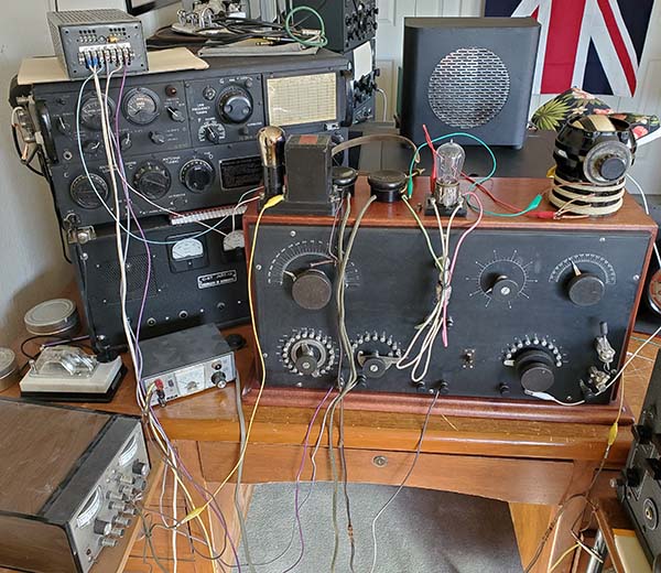
I had to move the SARX into the ham shack in order to have access to a large, outdoor antenna and a good ground (counterpoise and house ground.) Almost immediately, I tuned in strong signals (for a crystal detector) coming from KPLY 630kc and from KKOH 780kc, both Reno AM-BC stations. The first detailed test was to see what the actual tuning range of the receiver was. I set up the HP606B connected to a 30' wire so I could have strong coupling to the receiver antenna input.

Tuning Range - I started at 400kc and was able to quickly tune in the test signal. Next, 200kc. Again, easy to find and tune in. 100kc was next but it seemed that some of the turns on the LC were not connected (possible internally open, I'll have to check.) I think 100kc would tune but it would be close to the low end of the range. The next test was at 1000kc and this was tuned in easily. Next was 1500kc and to my surprise, I could just tune in 1500kc. It was at the very upper limit but it could be tuned. I had the coupling set to very, very loose for these tests to allow sharp selective tuning,...well, as sharp as a Loose Coupler can get.

However, when tuning stations over the air the results are different. When connected to a large antenna with a good ground, AM-BC signals are strong but it's impossible to tune the receiver selectively any higher than about 1000kc (even with very loose coupling.) There's a 10kw AM-BC station located 15 miles away in Carson City transmitting on 1300kc. It's a very strong signal here in Dayton and it broadcasts distinctive programming that's easy to recognize. However, I absolutely could not tune in 1300kc at all. Even with tight coupling, the 1300kc station wasn't heard. Due to the lack of selectivity, the 50KW KKOH seems to dominate the capabilities of the SARX and prevents "finding" weaker stations.

By "pounding a signal" into the SARX with a signal generator, I could tune to 1500kc. But, with "over the air" BC signals, I'd say 1000kc is the realistic upper limit of tuning. To get a response at 1000kc required fairly tight coupling with a corresponding wide bandwidth. With loose coupling, about 800kc is the highest "over the air" frequency that can be tuned. Again though, the real problem is selectivity and powerful AM-BC stations dominating a wide slice of the tuning range when using "over the air" signals.

Built Before 1913? - So, the SARX tunes easily from 100kc up to 1000kc or, in wavelength, 3000 meters down to 300 meters. Best response and easiest tuning is from 500kc up to 1000kc. The tuning range does confuse the SARX's ultimate use and the dating issue. However, with a modern signal generator input, tuning to 1500kc was possible. As an amateur receiver, used post-regulations, I doubt if any distant ham transmissions could have ever been received except with careful set-up that would have required the assistance of a neighboring ham who could supply a test transmission. With a strong marker signal, the SARX could easily be set up to receive 1500kc. With no modern powerful AM-BC going on, finding the neighboring ham's signal wouldn't be difficult. Also, one does have to consider the broad signal from the damped wave spark transmitters being used and that most hams were on or just slightly above the 1500kc limit allowing that type of signal to be heard - especially if the transmitting ham was in the same neighborhood - even if the tuning wasn't optimized for 1500kc. Also, with tight coupling, the bandwidth would be increased and it might be possible to hear a 1500kc strong signal, even though it wouldn't be tuned very accurately. Subsequent adjustments could then be made to optimize selectivity and best response to the test transmission. Although a first impression might be that the SARX couldn't receive any stations operating at 1500kc and therefore the build-date must be pre-regulations, testing has shown the operation on 1500kc would have been possible.

Built After 1915? - Look at the header photo of Hiram Percy Maxim's station in 1915. He was one of the foremost hams of the time (co-founded the ARRL) and his station receiver, while using a Loose Coupler and Spherical Audion detector, is NOT a panel set but is the typical table-mounted components. I really think that looking at vintage photos of ham stations, it gives me the impression that the SARX is from 1915 or 1916 or even early-1917 for the build-date. The limit to "late date" would be the US entry into WWI in April, 1917 at which time the Navy imposed a total ban on amateur radio operations and that included any radio receiver operation.

Other Indicators -  The evolution of receiver design does figure prominently with 1915 seeming to be about the earliest date for the design. Lack of regeneration doesn't really seem to figure in too much since just as regeneration was beginning to become commercially available the WWI receiving ban was implemented in April 1917. Use of the "panel set" design is the most indicative of 1915 to early-1917 construction.

Questions About Commercial Use - Could the SARX have been a Commercial receiver? Well,...according to DeForest's information on the original Audion box, the Audion is ",...only for amateur or non-commercial purposes. They are not to be used for trans-oceanic telegraphy or telephony. Sale, distribution or use for commercial purposes constitutes an infringement of our patent rights." Additionally, DeForest indicates that the Audions are only for renewal purposes in DeForest Detectors (like the RJ-4.) If it was a commercial receiver, the SARX violates all of these conditions.

These patent-use statements might seem to eliminate the possibility that the receiver was professionally-built for commercial use. BUT, almost the entire development of radio, especially pre-WWI, was fraught with inventors, entrepreneurs and even companies violating licensing and patents, borrowing ideas and designs without regard. This practice was particularly prevalent in the West where the distance from the Eastern manufacturers and their patent lawyers seemed to isolate builders from any litigation into the late-1920s. So, the possibility of the SARX being a professionally-built receiver intended for commercial use can't be entirely dismissed based on patents.

End-user Definitions:
"Amateur" would be a ham or radio enthusiast building and using the receiver with a transmitter for amateur communications as a hobby for pleasure.
"Commercial" would be a receiver built by a professional builder and used for non-amateur communications or reception, such as at a Coastal Station.
"Enthusiast" would be a non-ham but interested in the hobby of building and listening.

Conclusion on the Build-date - So, could the SARX actually have been built before 1913? More like 1911 or 1912? I think it's extremely unlikely (more like impossible.) If I believed that the SARX was an amateur receiver that was built circa 1911 to 1912 to deflate that idea only requires comparing the SARX to the M. H. Dodd 1912 Wireless Station. The SARX is YEARS ahead of the Dodd station's receiver in design, construction and performance. It's certainly difficult to imagine that the two are contemporaries (see photos below.) Then carefully look at the 1915 Hiram Percy Maxim station shown in the header photo. Note Maxim's receiver is using a Spherical Audion Detector and a Loose Coupler tuner but, like most amateur stations of that time, components are table-mounted with inter-connection wiring,...in other words, NOT a panel set. For the SARX, while a professionally-built, commercial receiver from about 1915 to 1917 can't be completely dismissed, I think the most likely builder was a very talented ham from 1915 to early-1917. This is based on its "panel set" design and use of the Spherical Audion tube but still built without regeneration. And,...even more photographic evidence below with the August 14, 1916 ham station photo.

Could both of these receivers have been built in 1912?

On the left, the M. H. Dodd receiver from his 1912 Wireless station. This station is accurately dated and documented from the many original photographs and from Dodd's literature.

On the right, the Spherical Audion Receiver.

How could it possibly be a contemporary of the Dodd's Station receiver?

To read about the M. H. Dodd 1912 Wireless Station, there's a comprehensive write-up with several 1912 photos of Dodd and his station on this website. Use the Home-Index at the bottom of this page for navigation.

Dated Photograph - Aug 14, 1916 - Another reference for dating the SARX is an old portion of a dated photograph of a ham station. Unfortunately, the ham call (if he had one) isn't written on the back but the date is - "8-14-16" - making the photograph very important for showing what type of equipment was in use at the time. Very apparent is the Spherical Audion control box in the center of the photo - and the audion has its filament illuminated! To the left of the control box is a Loose Coupler. Unfortunately, most of the Loose Coupler is missing because of the torn condition of the photograph but it does appear to be a "Navy-style" LC. In front of the LC is a crystal detector and a phone condenser. The meter is hanging on a nail and was probably for measuring voltages. I'm not sure what the device is setting on top of the Audion control box - it isn't connected to anything. Judging by all of the contact switches it probably is some type of coil loading device - maybe for tuning longer wavelengths. The phones are standard types. On the right side of the table is a transmitting oscillation transformer, sending key, a telegraph sounder and an adjustable device for some purpose. The photograph is torn and is probably just a portion of what was originally in the picture. But, what makes the photo important is the date on the back. It shows that in August 1916, Loose Couplers were still in use. Spherical Audions and control boxes were still in use. Construction was still individual components inter-connected on top of a table.

Evidence, like this dated photograph, seems to push the SARX build-date even later than I thought. Perhaps 1916 to early-1917? What about the date-limit of the WWI Navy ban on amateur wireless operation? Since the ban was on receiver operation did that also include building radio equipment? Would it have been possible for an amateur to build the SARX during the WWI Navy ban in anticipation of using the receiver after the ban was lifted? The build-date might be even later than I think. Hmmmm.

Be sure to check the Addendum at the end of this write-up regarding using the Murdock No. 344 Loose Coupler. Particularly note that the drawing shown of a Loose Coupler-vacuum tube detector station is copyrighted by Scientific American in 1922!


Non-Regenerative Vacuum Tube Detector - 2022 Testing has Very Different Results Compared to 1989 Testing

The improvement using a vacuum tube detector over a crystal detector is absolutely AMAZING with much, much louder signals - not just "slightly more sensitive" as I had reported in the 1989 ARC write-up - this time the vacuum tube detector is incredibly more sensitive providing a tremendous increase in signal strength compared to the crystal diode 1N34. It's interesting that DeForest mentioned the Audion's increased sensitivity over a rectifier detector in his article "How the Audion was Invented" published in the January 1947 issue of Radio-Craft magazine. He said that the rectifier only had the signal voltage as its source potential for current flow. Although DeForest, in the article, was comparing the Audion to the Fleming Valve, the point was that the Fleming Value or a mineral detector are only rectifiers relying on the signal voltage alone while the Audion detector plate had the B battery voltage within the circuit and that increased the level of potential and current available resulting in an increase in Audion detector sensitivity. This time, in 2022 testing, the results back-up what DeForest wrote with the vacuum tube detector dramatically improving sensitivity when compared to a simple rectifier,...or a crystal detector.

As to why my initial tests back in 1989 seemed to indicate that a vacuum tube detector was only "slightly more sensitive" than a germanium diode,...hmmm,...what can I say? I don't remember using a good emission UV-200 soft detector during those tests. Certainly, this particular UV-200 probably has much more emission and is a better detector tube than whatever I was using over 30 years ago for testing. I'm sure I wasn't adjusting the plate voltage back in 1989. It's of paramount importance that both plate and filament voltages can be adjusted so the best combination of both voltages can be found. This proper voltage combination is very important for good sensitivity and when the right combination of filament and plate voltages are found the increase in sensitivity is incredible and especially beneficial to DX reception when no regeneration is being used.


A Performance Enhancing Experiment for 2022 - Regeneration? Audio Amplification? Both?

Of course, the first thought would be why not connect the 'phones output to a two-stage audio amplifier? Well, that was how the WWI SCR-59 airplane receiver circuit worked - non-regenerative detector with two stages of audio amplification. But, I wanted to see if a loose coupler receiver could be connected up to work as a regenerative detector receiver. Certainly by the time regeneration was in common use, after the WWI ban was lifted in April 1919 for receiving, the loose coupler was rapidly becoming obsolete due to its lack of selectivity and difficulty in tuning. It should be an interesting experiment. I may also try the audio amplifier circuit too. Maybe both,...simultaneously. Both regeneration and audio amplification can be accomplished using external components and existing terminal-type connections with NO MODs to the Spherical Audion Receiver.

Years ago, when I wrote "Regeneration would have been a big help,..." I didn't really think then about how easy it would be to externally add regeneration to the Spherical Audion Receiver without any modifications,...only requiring a couple of additional components that could be connected up to existing terminals to create a regenerative detector. So, having thought about regeneration with a Loose Coupler as a tuner, I thought I'd go ahead and experiment with the Spherical Audion Receiver and see how an "external components" regenerative detector circuit would work.

I wasn't going to use the vintage NOS Deforest Spherical Audion I have and the two Tubular Audiotrons I have are both open filament display tubes. I don't have the good dual filament Audiotron or the Moorhead ER tubes anymore (damn tube collectors are always offering good trades I can't resist.) About the earliest tube I could experiment with would be a pure tungsten filament soft detector tube, a UV-200 from about 1922. I would have to build up another tube socket adapter to interface with the Spherical Audion socket on the receiver (I don't have any idea where my first socket adapter went to.)  

The circuit of the SARx has the secondary of the loose coupler connected to the grid of the detector tube though a grid-leak resistor (actually, a piece of carbon-paper) and blocking capacitor. The plate of the detector tube is connected directly to the binding post for B+/B battery connection and with the B-/B battery terminal going to the switch to select Crystal or Tube and then to the 'phones terminals and finally to A+/Ground (no phone condenser.)   >>>

>>>  Since the SARx has separate B battery terminals, it's possible to connect a variometer (the variometer rotor should connect to the tube plate) to the detector plate by using the B+ terminal that's connected directly to the tube plate and then at the output side (the stator) of the variometer (external to the receiver) connect a set of earphones (with a bypass condenser across the phones) to a B battery that's not connected to the B battery terminals on the receiver. The minus connection of the B battery would be connected to the A+ terminal of the receiver for the proper return. With this connection, there is a weak feedback path via the interelectrode capacitance of the detector tube and the variometer allows tuning the plate to resonance with the grid tuning allowing some feedback to occur. Stray coupling dependent on the variometer's location could also contribute to some feedback.

Usually, a more intense feedback path is needed since the interelectrode capacitance is somewhat limited (g-p resonance will increase sensitivity but it's usually not enough to cause oscillation.) Mounting the secondary coil on the variometer was the most common method used but that's not practical with a Loose Coupler. However, it was possible to mount a portion of the secondary coil directly on the variometer with this coil becoming a "Tickler Coil." The Tickler coil is connected in series from the secondary coil to the grid of the detector tube. Proper connections in the plate circuit to the variometer will cause the phase reversal that allows in-phase coupling to the grid circuit tickler. The variometer adjustment increases the plate-grid EM coupling as its EM field increases as the plate approaches resonance with the grid circuit. This increases the feedback and control of the regeneration. The object of the experiment is to create a regenerative detector circuit without changing anything in the SARx. 

The External Components Needed

Vacuum Tube Socket Adapter - This consists of a standard bayonet-type tube socket that accepts short-pin, UV-style tubes such as the UV-200 soft detector tube. Filament wires are connected to a screw-in lamp base with the center button being F+ and the shell being F-. Grid wire is color coded green and the plate wire is color coded red. I'm testing with the soft detector tube since it has a little bit of Argon gas in the envelope and DeForest's early Audion tubes also had some gas (although it was just residual air) that he claimed helped the sensitivity of the Audion tubes. The UV-200 takes about five minutes of filament on operation to warm up the Argon gas for good sensitivity. The tube socket has a fairly large base that allows the tube to set on top of the receiver cabinet. 

Variometer - Six years ago (in 2016,) I performed a second restoration on my 1922 Colin B. Kennedy Type 220 Intermediate Wave Receiver. Left-over from that restoration was a complete and functional Kennedy variometer along with the secondary to grid Tickler coils. This unit provides everything needed to turn the non-regenerative detector of the SARX into a regenerative detector receiver.

In addition to outboard regeneration,...why not an outboard stage of audio amplification too?

Audio Amplifier Unit - The Audio Amplifier is a Pilot Radio "Uni-blox" single stage AF amplifier. Interstage transformer input, UX-201A hard amplifier tube and the 'phones are connected between the plate and +90vdc B+. With the 'phones moved, the Detector B+ connects directly to the variometer stator. A single stage of audio amplification will produce very strong signals in the 'phones. It can drive a horn speaker on strong AM-BC stations but weak DX reception using a horn speaker would be difficult with just one audio amplifier stage. 


UV-200 in socket


Colin B. Kennedy Variometer and Tickler Coils


Pilot Radio "Uni-Blox" Single Stage Audio Amplifier

Regeneration plus Audio Amplification Testing

Regeneration - Adding regenerative feedback required a bit of experimentation. I first tried just using a General Radio 107K variometer and while there was a very noticeable and definite "peak" in sensitivity level at 450uh (with the receiver tuned to around 350 meters,) there wasn't sufficient feedback for any oscillation. So, just the tuning of the plate to the grid and relying on the inter-electrode capacitance of the detector tube doesn't provide the tremendous feedback needed for oscillation and peak sensitivity. There were a couple of regeneration methods that were used on two excellent post-WWI performers. The Navy SE-1420 receiver from 1919 used a special variometer that allowed connecting one of the stator windings to the plate circuit and the other stator winding to the grid circuit. This gave excellent proximity for EM coupling that could be adjusted by the variometer rotor position. The second method was in the 1922 Colin B. Kennedy receivers. Kennedy used a standard variometer in the plate circuit but added a set of tickler coils mounted on the underside of the variometer. This proximity provided the EM coupling from plate to grid and the variometer allowed adjustment of the feedback. I experimented using an external tickler coil with the GR-107K but its internal structure prevented using it for a "full-on regenerative detector." Luckily, I had another variometer that was perfect for the job. It was a spare Colin B. Kennedy unit out of a Type 220 receiver.

Regeneration with Variometer and Tickler Coil - The 1922 Colin B. Kennedy receivers all had a "secondary coil in series to detector grid" coil that was mounted just under the variometer. This grid coil acts as a "Tickler Coil" providing a feedback path from plate to grid by its location. The variometer "tunes" or "detunes" the feedback by resonating the plate (variometer) to the grid signals (the tickler) and to a certain extent coupling through the inter-electrode capacitance of the detector tube. Normally, the grid and plate are 180º out of phase but proper connection of the variometer rotor will reverse the phase relationship in the variometer and allow increasing the EM coupling as resonance is approached. As the variometer rotor in the plate circuit comes near to resonance, its increasing EM field couples to the tickler coil which adds to the grid signal (by essentially becoming positive feedback) and amplification starts to happen. If the variometer is adjusted too far, then the plate to grid will have too much in-phase resonant coupling and then the excessive feedback breaks into oscillation and the detector becomes an autodyne detector, capable of demodulating CW signals.

The increase in sensitivity can be tremendous allowing several AM-BC (below 1000kc) to be tuned. As a non-regenerative detector, only two local AM-BC stations were heard during the daytime (and only KKOH was strong.) With regeneration it seemed like more stations could be tuned-in, though not easily. Using a Loose Coupler even with the air variable condensers is still very difficult to adjust and tune making changing stations a time consuming operation. Each change to a new station seemed to require complete retuning of each adjustment. Filament and plate voltages both affect regeneration. Every adjustment somewhat interacts with all other adjustments. Syntony was still primitive using Loose Couplers. The earliest commercially-built regenerative detector receivers used variometers and fixed-value condensers (the LC) for frequency tuning to achieve the selective syntony needed but lacking in a Loose Coupler.


No awards for neatness here! This is the SARX with external components hooked-up to create a regenerative detector plus one stage of audio amplification. Note the three power supplies, the 6v 4a Lambda on top of the ART-13, the +20vdc detector B+ to the left of the SARX and the +90vdc amp B+ far left. Despite the mess, it works!

Regeneration plus Single Stage Audio Amplification - I had to use an old solid-state A-B-C battery eliminator that I built years ago as a +90vdc voltage source. B- was referenced to A+. The Filaments were hard wired to the A supply (that had extra screw terminals to make it easy.) Clip leads were used for the other connections. When power was applied, I didn't have the 'phones "on my head" but the signal from KKOH was so strong it could easily be heard with the 'phones setting on the desk. The detector filament voltage could be reduced a little now. Detector plate voltage was at about +20vdc. With regeneration, selectivity seems better and that's expected when setting the feedback very near the oscillation point. It's very easy to induce feedback oscillation - at least while tuning above 500kc. I had to use the first two feedback coils in series on the Tickler (there are three total on the Kennedy variometer and tickler combination.) A single tickler coil didn't produce any oscillation and using all three coils produced uncontrollable oscillation.

Now, this regeneration and audio amplifier set up is far from stable nor is it easy to use. Tuning to different stations requires several readjustments because everything interacts and needs to be "re-peaked" after each change. I also found that I couldn't get the "hook-up" to oscillate below 500kc. There was an increase in sensitivity but I couldn't get the detector to break into oscillation at frequencies below 500kc. I'm sure if the connections weren't "a bunch of clip-leads" and "long connection wires" (as can be seen in the photo above) that I could probably get the regeneration to have a wider range. In fact, with subsequent testing, I discovered that the tinsel-wire cable from the variometer output to the audio amplifier input was intermittent and causing the regeneration to also change intermittently. Replacing this wire helped substantially with a much more consistent feedback and that stability allowed extending the tuning up another 200kc (from 780kc KKOH up to 980kc KHOG.) Even though changing stations is a real hassle and the regeneration range is very limited, this "hook-up" does basically work,...maybe not as well as expected though. Most importantly, I have to remember, this experiment was to use ALL external components and NO modifications to the receiver to achieve regeneration - and that does work.

For the Best Results Just Audio Amplification with a Vacuum Tube Detector - So, creating a vacuum tube regenerative detector using a Loose Coupler tuner is possible. BUT,...I've found through experimentation using the Spherical Audion Receiver that the BEST overall performance benefit comes from just adding audio amplification. While regeneration with external variometer-tickler coil assembly does work, it's very difficult to tune multiple stations. I could find one station, tune to enhance that station but ANY change would either result in oscillation or the inability to tune any other station unless the entire set of adjustments started over. It's much, much more stable to use the detector just as a grid-leak detector and then insert an audio amplifier to boost the audio levels. In this set-up, stations could be easily tuned and "peaked" without any effort. Also, maximum selectivity could easily be achieved (very loose coupling) without total de-tuning or loss of signal. So,...the recommendation for a Loose Coupler Vacuum Tube Detector receiver is to add a stage or two of audio amplification. That will give the best results possible. Regeneration and tuning with a Loose Coupler, while possible, is too difficult to adjust for multiple station tuning - it only works well for one station at a time.

Wrap-up - It was a fun experiment and an interesting look at the development of radio circuits at a time when the ether was in chaos with multitudes of spark transmitters with helix couplers producing harmonics "from DC to sunlight" and receivers that could reproduce a 1000kc bandwidth all at once! To demonstrate the evolution through testing the Spherical Audion Receiver with it first having an ultra-wide tuning bandwidth and zero sensitivity when using a vintage galena crystal to the slight improvement using a vintage 1N34 germanium diode,...then to experience the vast improvement that a vacuum tube detector brought on, as far as sensitivity,...and then, the tremendous improvement in both sensitivity and selectivity that a regenerative circuit but to also discover the difficulty in keeping a primitive regen set adjusted and subsequently discovering that just adding an audio amplifier to a non-regenerative vacuum tube detector circuit could bring in strong signals, easy adjustability and a real improvement to the SARX's performance. It was an exciting experiment. Maybe not as exciting as it was to the original inventors, but I had fun anyway.  

Addendum - Testing the Murdock No. 344 Receiving Transformer


Wm. J Murdock Co. No. 344 Loose Coupler

I suspected that the LC in the Spherical Audion Receiver had some winding problems that were preventing tuning the full range on both the primary and secondary windings. To follow-up on the idea of using a Loose Coupler with a vacuum tube detector, I thought I'd try a different Loose Coupler to see if I could tune different ranges that the Spherical Audion Receiver seemed to have problems with. First, I wanted to see if it would be EASY to tune to 200 meters. Next, would it be EASY to tune below 600 meters or 500kc? I decided to use the Wm. J. Murdock Co. No. 344 Receiving Transformer. It's a small LC that was positively being sold after 1913 and was specifically for ham use (and it was priced low at $7 in 1914.)


photo right: Page 155 of Morgan McMahon's "Vintage Radio" had this drawing showing the hook-up for a vacuum tube detector used with a loose coupler. NOTE that the copyright date is - 1922 - from Scientific American Inc.

The first test was to test the DC resistance of the windings to make sure I had complete coils for both the primary and the secondary. Both had full continuity. The next test was just to see if the No. 344 even worked as a crystal receiver. I used a 1N34 germanium diode detector with Baldwin phones and was easily able to tune in 50KW KKOH 780kc using a 162' end-fed wire with counterpoise-ground.

The next test used the UV-200 soft detector tube. I used a 2meg grid leak resistor and a 260pf grid blocking capacitor. The power supply for the plate voltage was adjustable. I used a vintage variable resistance to adjust the filament voltage. I used the tube socket adapter I made for the SARX to connect the UV-200 into the circuit. The vacuum tube grid-leak detector is a tremendous improvement over the crystal detector providing very strong signal response.

The last "hook-up" was to add the audio amplifier. This resulted in really strong signals. I could tune in three daytime stations once I added a Murdock variable condenser in parallel with the secondary coil. Now, could I tune to 1500kc or 200M? It required a marker signal. I used the HP 606B coupled through a .001uf cap to the antenna post with a .3vrms signal. This was easily heard and the LC and tuning condenser could be then adjusted for maximum signal. Once the positions were set, the wire from the HP-606B was just dropped on the floor and the signal was still easily heard. This same procedure was used to tune 1300kc to see if I could hear the 10KW station in Carson City about 15 miles from here. With maximum selectivity and the signal peaked using the marker, I was just able to hear a station other than 50KW KKOH but I really couldn't verify it was the Carson City station because KKOH was so dominate. Same test at 500kc and the marker could be tuned easily and the signal picked up with the signal generator wire on the floor. KPLY on 630kc was still being heard indicating that even at maximum selectivity the bandwidth is still in excess of 100kc. Same test at 300kc with the marker easily tuned in and although noticeably weaker than on higher frequencies, still the signal could be heard with the signal generator wire on the floor. No other stations heard, so selectivity is good enough to not pick-up any AM-BC stations when tuned to 300kc.

My conclusion is that 200M or 1500kc was easy to tune using this size LC. In fact, tuning down to 300kc was easy, as long as a marker signal was available. The big problems, which didn't exist pre-1922, were from powerful AM-BC stations. Selectivity is just not very good when using a loose coupler. In fact, loose couplers can't provide enough selectivity to prevent picking up local AM-BC stations at just about anywhere that the loose coupler can be tuned. But, in the pre-broadcast days, using one stage of audio amplification with the vacuum tube detector provided very strong signals and certainly would have been able to function as a ham receiver in the pre-1920 time period.

Another conclusion from testing these loose couplers is that they certainly must have performed much better when they were new. With over 100 years of existence on the planet, they all do have some wear, some oxidation and lots of contact problems. But, as "collectibles" we try to keep everything as original as possible. Testing the larger Murdock No. 334 Loose Coupler, I couldn't get any continuity anywhere due to the heavy tarnish and patina. This smaller Murdock No. 344 was very clean and did have continuity but still switching contacts and sliders were very noisy and sliding the secondary coil also had some minor contact problems. I wonder if tuning a loose coupler was nice and quiet when they were new?


photo left: The Murdock 344 LC vacuum tube detector receiver. The Pilot Redi-blox Audio Amplifier is out of the shot to the left.

Henry Rogers © Oct 2022


Return to Home Index


Radio Boulevard
Western Historic Radio Museum

 Vintage Radio Communication Equipment Rebuilding & Restoration Articles,

 Vintage Radio History and WHRM Radio Photo Galleries

1909 - 1969

- 60 years of Radio Technology -


This website created and maintained by: Henry Rogers - Radio Boulevard, Western Historic Radio Museum © 1997/2023