|
Circuit Description
- The AR-8516 was
a thoroughly modern (well, for the late-fifties,) complex communications receiver that used 18
tubes in a single, double or triple conversion superheterodyne circuit. The
receiver used a variably-tuned IF covering 1.09 to 3.09mc or 2 to 4mc.
The fixed-frequency IFs were at 455kc and 45kc. Single conversion was
used in the first five bands covering 80kc up to 4mc. Bands 1-4 span
different widths of the LF and MF spectrum and, along with Band 5, these
single conversion bands tune from left to right being from high to low
in frequency. From 2mc up to 30mc is
covered in fourteen 2mc-wide bands. Band 5 (2-4mc) is single conversion
but Bands 6-18 are double conversion. The double conversion bands (Bands
6-18) tune left to right being low to high in frequency. The total frequency coverage is
from 80kc up to 30mc in 18 tuning ranges. Seven crystals are utilized in
the Crystal Oscillator with only two crystals used uniquely. The other
five crystals are used in various fundamentals and harmonics for a total of 13 crystal
oscillator frequencies. The RF amplifier, Crystal Oscillator and Mixer 1
circuit function as the RF input for bands 6 to 18 with the output going
to the Variable IF tuning that then provides a fixed 455kc output. The RF input section is
bypassed when using bands 1 to 5 and the incoming signal goes to the
Variable IF which combines with Mixer 2 and the selected VFO to provide
a 455kc output. Two separate VFOs are used with one
used for Bands 1, 2 and 3 and the second VFO used for Bands 4 to 18.
Main tuning gear reduction is 41.7 to 1 and the SECTOR gear reduction is
another 3.8 to 1. The resulting tuning is a constant "bandspread"
type at almost a vernier tuning rate.
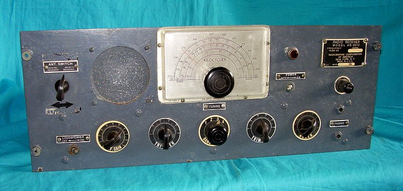
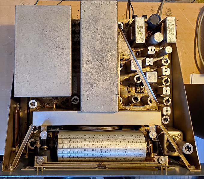
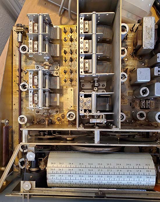
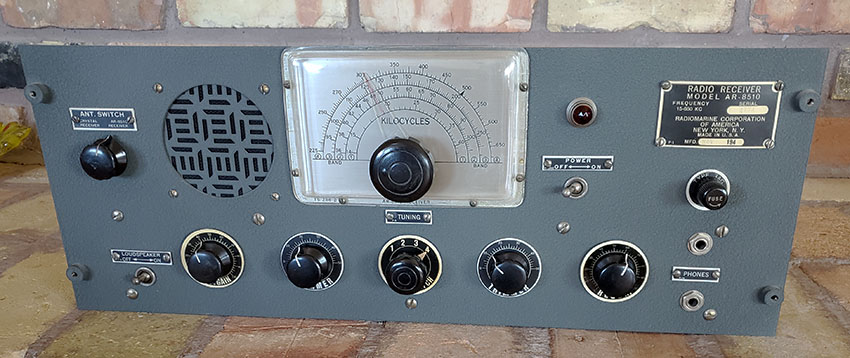
The dial readout is "band-in-use" and employs a rotating
dial drum that is ball chain-coupled to the band switch. The smaller
dial to the right is the kilocycle-logging scale which for Bands 1-4 is
a logging scale, but, since the Bands 5-18 are 2mc linear scales for
each band, if the receiver is well-aligned, then this dial will readout
frequency almost directly "to the kilocycle" for
these bands.
For example, if the slide-rule dial pointer is set in between 14.1 and 14.2 and the
logging dial reads 67, then the tuned frequency is 14.167mc. The
kilocycle dial
index is not adjustable. The accuracy of alignment will determine just
how usable the kilocycle dial ends up being. Spec from 4-30mc is "within
10kc." I was able to achieve an average tracking accuracy of between "dead on"
up to the greatest error being about 5kc off. Below 4mc the accuracy spec is 0.5% which is easily attained
during alignment (at 4mc the spec of 0.5% is 20kc.)
Bandwidth is selectable from 6kc
down to 100hz (five steps) in Bands 3 to 18 but in Bands 1 and 2 the
bandwidth is selectable only from 1.5kc down to 100hz in three steps
(6kc and 3.1kc, if selected, won't change from 1.5kc bandwidth.)
The selectable bandwidths provided are 6kc, 3kc, 1.5kc, 800hz and 100hz. The
3.0kc bandwidth utilizes a Collins 3.1kc mechanical filter and the
1.5kc, 800hz and 100hz bandwidths are also derived through the 3.1kc
mechanical filter going then to the 45kc IF which is
utilized for two purposes. In Bands 1 and 2, 45kc is the IF. In Bands 3
to 18, the 45kc IF is utilized as part of the selectivity bandwidth
operation and results in triple conversion in the IF section if
1.5kc, 800hz or 100hz bandwidths are selected. Two types of
detectors are used with a standard vacuum tube diode detector used in Bands 3
to 18 and a crystal diode detector (heavy duty 1N34 germanium diode) utilized in
Bands 1 and 2. Two BFOs
are also used with the 455kc BFO being adjustable +/- 2kc but the BFO
for 45kc (which is used just for bands 1 and 2) utilizes a fixed-frequency
(adjusted for a 1kc heterodyne or 44kc.) When SSB is
selected the 455kc BFO output is increased (compared to the output in CW) for better demodulation of suppressed-carrier signals. AGC has
selectable fast and slow time constants. The audio output frequency
response is 200hz to 3000hz (-4db down) and the audio power available is
250mW with 3.2Z or 600Z impedance outputs provided. A 500kc Calibration
marker signal is available that functions from the 500kc Crystal
Oscillator that also provides mixing with 455kc IF for the 45kc IF. A carrier level meter (showing db above
1uv) is provided. The ANTENNA (trimmer) control is connected to RF/Mixer
1 and only functions when the receiver is on Bands 6-18 (4-30mc.)
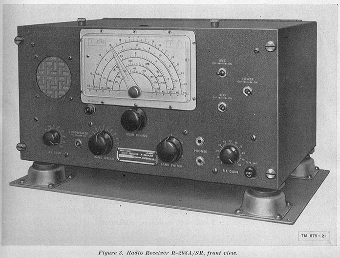
Radiomarine also offered a very similar receiver that
was designed for AC line power application at any land-based
communications operation (like RMCA Coastal Stations.) The
CRM-R6A has many slight differences but it's basically the same type of
design as the AR-8516, both electronically and mechanically.
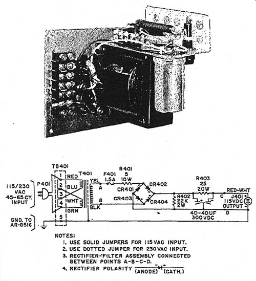
Power Requirements
- Being a commercial shipboard receiver, the AR-8516 is
designed to be powered by various types of ship's power systems. It was expected
that the receiver would be powered by +115vdc. Using
accessories available from RMCA, operation on +230vdc was also possible.
It was also possible to operate the receiver direct on 115vac but the
receiver's power
input section only provides a half-wave rectifier if AC operation
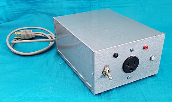
is used. RMCA recommended that the MM-555140-B Isolation Transformer/DC supply be used to
convert the ship's 115vac (or 230vac) to +115vdc for operation of the receiver. In
fact, if the receiver was ordered with the matching table cabinet, then
the MM-555140-B was included and installed inside the cabinet. If the rack
mounted version of the receiver was ordered then the MM-555140-B was
separate and was installed externally (somewhere in the rack.) Since the
AR-8516 is AC-DC in concept, all tube filaments are wired in series.
Most of the tubes are 3-volt filament types, e.g., 3BZ6, 3BE6, 3CD6,
3AL5, etc. but
(2) 5U8, (3) 7AU7 and (1) 12CU5 tubes are also used.
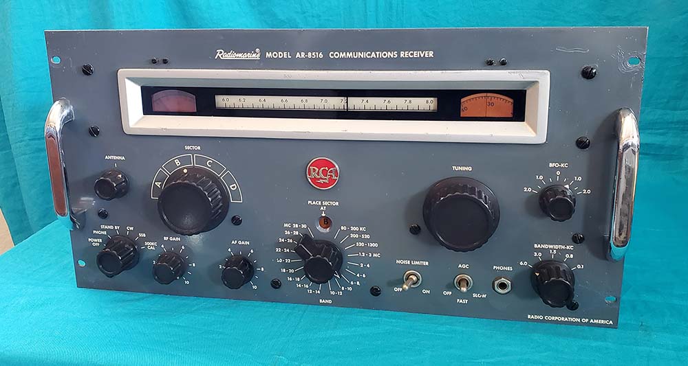
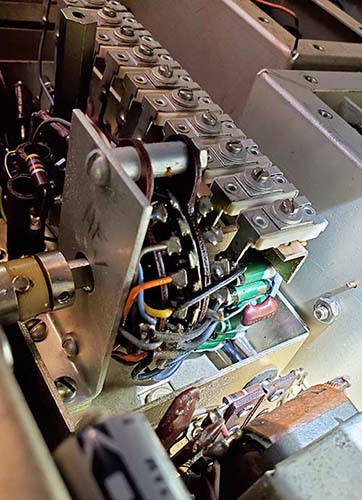
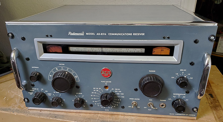
The SECTOR Control
- The unfamiliar control on the AR-8516 is the SECTOR control
which is part of the RF and Mixer 1 tuning in combination with the
Crystal Oscillator. When the receiver is tuning
from 80kc up to 4mc (first five bands) the RF and Mixer 1 circuits are
bypassed and the Variable IF (acting as a RF amplifier, VFO and Mixer 2) tunes the receiver as a single conversion circuit.
When tuning above 4mc, double conversion is used and the SECTOR control
provides the correct tuning for the RF and Mixer 1 (and Crystal
Oscillator) for each of the 2mc wide bands (4mc to 30mc.) Four sets
of coils are used for ranges 4-12mc, 12-20mc, 20-28mc and 28-30mc. When
combined with the selected Crystal Oscillator frequency the result is
2mc wide tuning ranges from 4 to 30mc. The "sector" refers to each 45
degree section (A, B, C or D) of the RF/Mixer 1 variable tuning
condenser's 180 degree rotation range. Selecting A, B, C or D will
actuate a physical rotation of the RF/Mixer 1 tuning condenser rotor to
the correct 45 degree section required for tuning (plus the Crystal
Oscillator) of the particular 2mc band range selected. The SECTOR
switching is roller-chain coupled to the band switch. The RF/Mixer 1 tuning is gear-coupled to the main tuning
control and the SECTOR selector knob will rotate as the TUNING knob is
rotated. Although the SECTOR knob and RF/Mixer 1 condenser rotate with
the main tuning, the correct section selection is necessary and will
require that the SECTOR knob be set to the "detent" in the correct
A, B, C or D
position. The "PLACE SECTOR AT" indicator is illuminated and located in
the viewing hole above the band switch. The main tuning dial, logging
scale and meter illumination are also controlled by the SECTOR control in Bands
6 to 18. These lamps will only
illuminate when the correct SECTOR
position is selected.
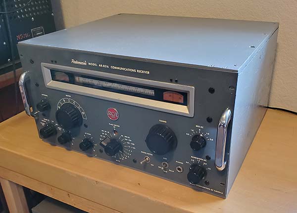
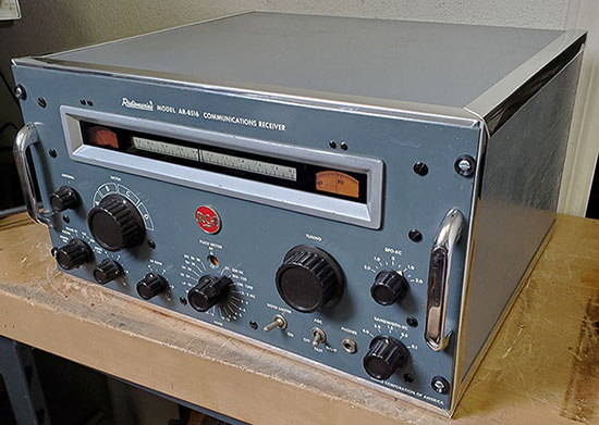
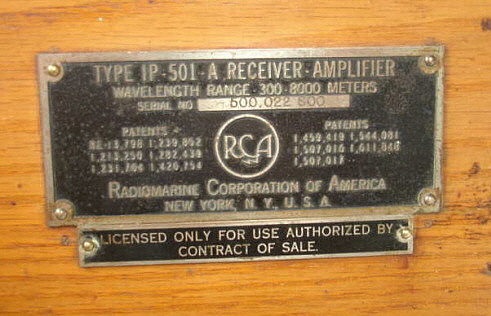
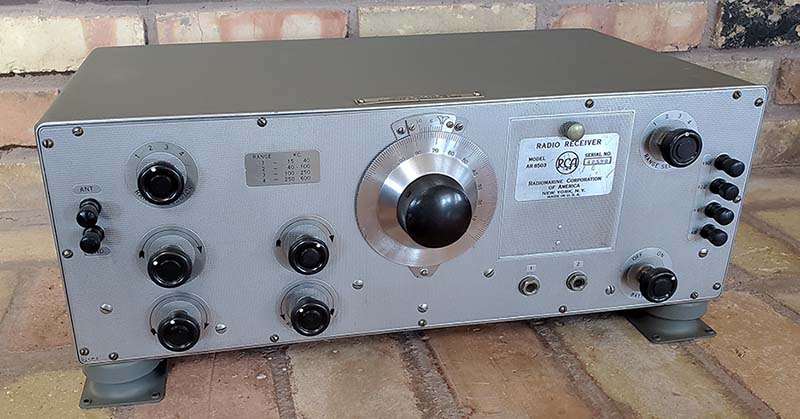
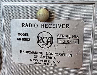
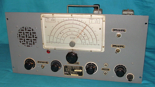
Serial Number and
Cabinet - The serial number of the AR-8516 shown is SN:5830. The
serial number incorporates the year of manufacture in the first two
digits, e.g., "58" is 1958 and the receiver number is "30." There is
also another tag mounted to the rear chassis that gives the month and
year of manufacture, in the case of SN:5830, the tag reads "JAN 1958."
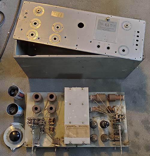
The odd size panel height of 9.5" (rather than the standard 10.5") does
limit the receiver's installation into generic-type cabinets without an
obvious gap. Mounting the receiver in a rack will solve that issue. Of
course the proper RCA cabinet does fit the receiver panel correctly but
finding one is next to impossible. As
stated in the manual, the AR-8516 was available as a table model
receiver with the cabinet (with the MM-555140-B installed) or it could
be ordered as a rack mount without cabinet (with the MM-555140-B as a
separate accessory.)
|

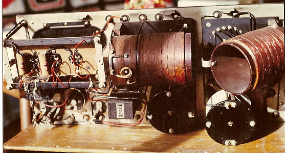
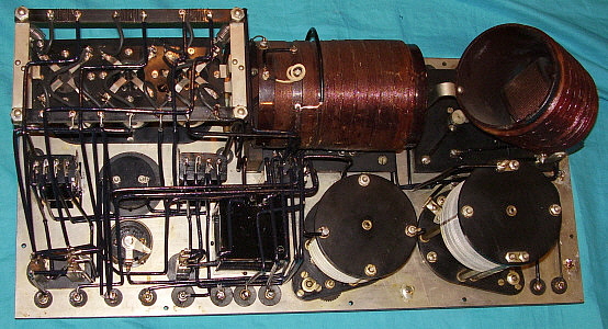
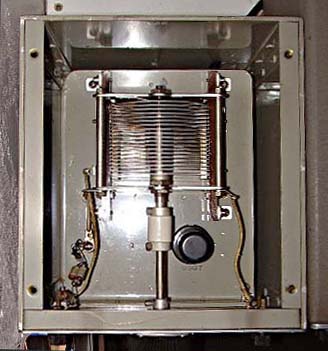
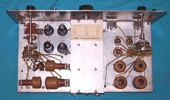
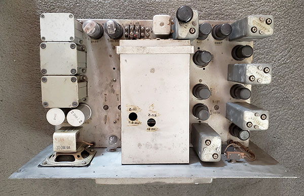
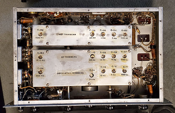
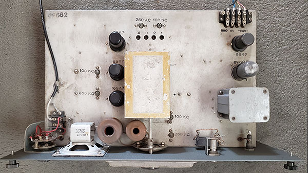
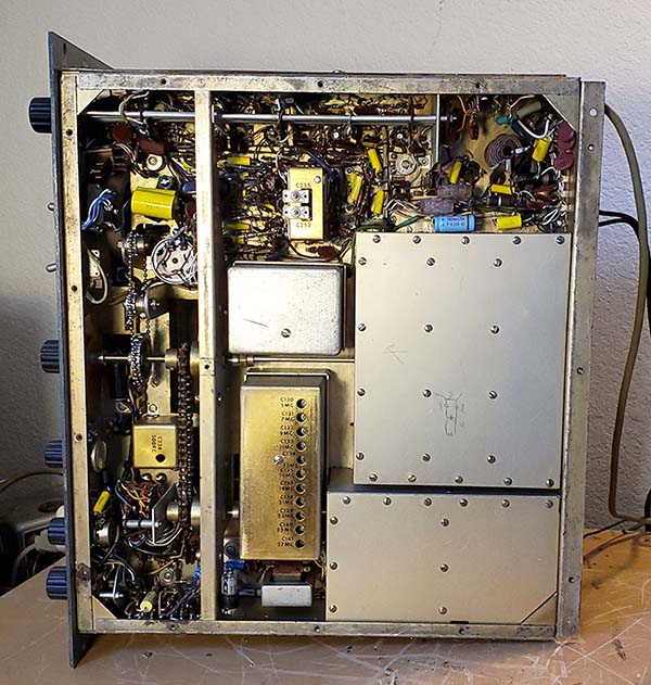
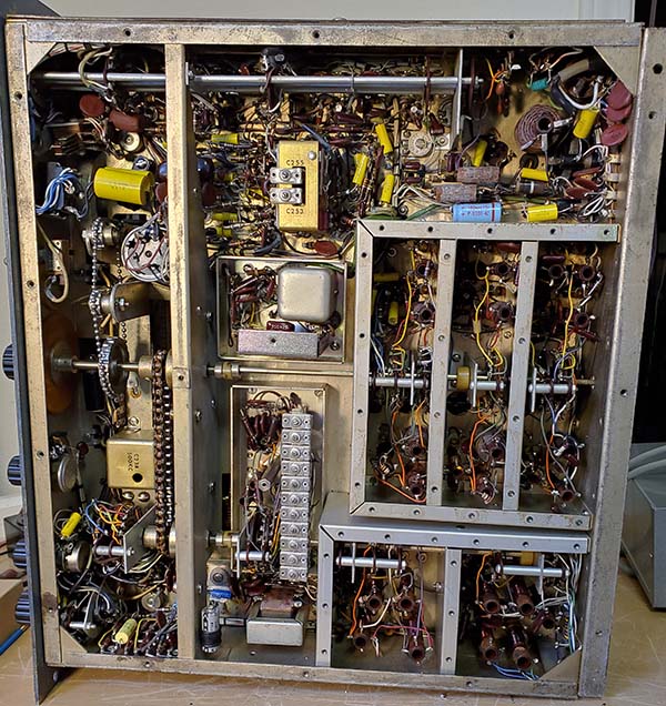
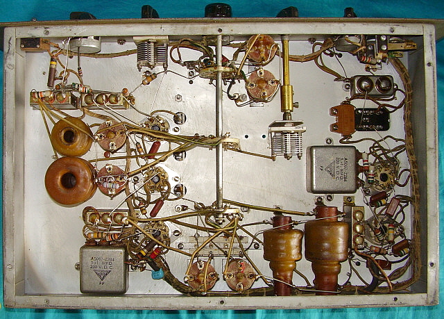 Under the chassis showing the bee's
wax impregnated coils.
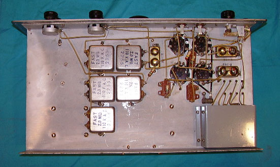
Under the chassis showing the bee's
wax impregnated coils.