Radio Boulevard
Western Historic Radio Museum


Navy Department - Bureau of Engineering

RAG-1  CHS-46042
VLF-LF-MW Receiver
 TRF Circuit with Tracking BFO

15KC to 600KC

Power Unit  CHS-20032
AC Power Supply
 

Contractor: Hygrade Sylvania Corp.

Contract Number: 32226   Date: July 13, 1933


by: Henry Rogers WA7YBS


1933 USN RAG-1 SN: 1   

The RAG-1 is a rare receiver. Only a small quantity were built on the "one and only" contract from July 13, 1933 (which was typical of Navy contracts in the 1930s.) Though the LF RAG-1 and its companion HF RAH-1 were the first examples of the Navy's concept of a reduced-size, lighter-weight, "pair of receivers" that offered frequency tuning from 15kc to 600kc in the LF receiver and 300kc to 23mc in the HF receiver. The two receivers could be operated by one radioman who could then "stand guard" on two frequencies simultaneously. Dual power supplies and a single control box allowed the radioman complete operational control of the RAG/RAH receiving system. So, what happened? Why are virtually no examples left of these initial concept receivers that eventually spawned the ultra-successful RAK and RAL receivers? None of the RAG/RAH documentation remains. Nothing. Was the Navy frustrated at the receiver's delicate construction that certainly must have resulted in numerous breakdowns at sea? Shipboard operational survivability, for some reason, wasn't part of the RAG/RAH design and ultimately all of these reliability-challenged receivers were removed from Navy ships by 1939. The only description of these receivers is in the Navy Procurement catalog but that listing has no photos or drawings,...only a basic description of the receiver's conceptual design.

The Tuned Radio Frequency Receiver with Tracking BFO - History

Before WWI, the Navy published in their wireless books that vacuum tubes were unreliable. Their detector of choice was a silicon mineral. After all, what could go wrong with it?,...it was a "rock!" But, the Navy wanted better performance and, when the SE-1420 was developed in 1918, that radio receiver's ability to extract weak signals out of the ether and amplify those signals to thunderous volume levels impressed the Navy Department. Hundreds of SE-1420s and their variants were produced just after WWI ended and well into the late-1920s. During the 1920s, the SE-1420 was improved upon becoming the IP-501-A and by the late-1920s the RE, RG, RO and other types of shipboard receivers were being developed. What these receivers had in common was their regenerative detector circuit.

The regenerative detector was certainly sensitive, especially when proceeded by a primary circuit that exactly tuned the antenna load and allowed adjustment of the coupling of the antenna energy to the tuned input of the detector grid (secondary circuit.) These early shipboard CW receivers, with their oscillating detectors, did allow a lot of energy back onto the antenna and the regenerative radiation was a concern since it interfered with other radio equipment,...many times equipment on other nearby ships. To increase sensitivity and to reduce detector oscillation energy from being radiated from the receiver antenna, RF amplifier stages were added ahead of the detector.


photo above: Wireless Specialty Apparatus/RCA version of the IP-501-A regenerative receiver from 1924-26

The detector remained regenerative to take advantage of its autodyne ability, that is, it could detect and oscillate simultaneously thus providing a receive-frequency heterodyne to demodulate CW signals. These receivers were classified as TRF receivers with Regenerative Detectors.

TRFs, or Tuned Radio Frequency receivers with non-regenerative detectors, had been popular in the mid-1920s as AM BC radios and, while most were rather anemic performers, the Neutrodyne TRF circuit provided outstanding sensitivity and excellent reception. However, for the Navy, the receiver had to be capable of CW reception. Also, the Navy wanted a type of receiver that was easier to operate than a regenerative detector receiver and a receiver that provided consistent performance regardless of the radioman's experience.

The superheterodyne offered the possibility of that consistent performance since many of its adjustments were somewhat "fixed" thus requiring the radioman to essentially just tune the dial and adjust the sensitivity. Certainly the improved selectivity afforded by converting the incoming RF signal to an intermediate frequency for better control of the overall amplification was also attractive to the Navy. The first longwave superheterodyne produced for the Navy was the gigantic RAA-1 receiver. This 1931 receiver, weighed over 400 pounds and had four different, two-stage IF amplifiers and four different frequency BFOs selected by the band switches on both the tuner and the IF amplifier sections. It was a mammoth receiver that was as complex as it was expensive. 

The Navy needed a receiver that was easier to maintain, easier to produce and was less expensive than the extravagant RAA and its HF companion, the RAB. Superheterodynes required particular design attention to the IF used. The Navy and other military-commercial users had numerous radio operations that were in the Medium Wave and Low Frequency parts of the spectrum. Most superhet conversions were in this part of the spectrum and, unless some IF manipulations were part of the design, as with the RAA, then certain sections of the desirable MW-LF spectrum couldn't be used.    >>>

>>>   The Regenerative Detector receiver allowed complete tuning from VLF up to SW but it could radiate interference and required some experience to obtain good sensitivity. There had been quite a bit of experimentation to further develop the TRF receiver with non-regenerative detector into a capable shipboard CW receiver. This would require adding a BFO circuit that would "tune" along with the other tunable RF-Detector stages - called a "Tracking BFO" sometimes referred to as a "heterodyne detector."

As early as 1901, Reginald Fessenden had experimented with a heterodyne detector that coupled a mechanical oscillator to a mineral detector receiver in order to detect CW signals from arc transmitters. Once the triode vacuum tube was invented, the tube oscillator soon was developed. Vacuum tube oscillators also produce continuous waves. Spark transmitters produced damped waves that were similar to a modulated CW signal that could be received with mineral detectors. However, arc transmitters, vacuum tube oscillators and Alexanderson Alternators produced CW signals. The heterodyne detector was necessary for receiving almost all transmitter types except spark transmitters. The heterodyne detector term usually implies that the oscillator used operates very close to the received frequency to produce an audible beat tone. Early oscillators were separately adjusted from the frequency tuning but the ultimate evolution was to have the heterodyne oscillator "track" the receiver tuning. Through the late-twenties, experimentation and early designs of TRF/Tracking BFO circuits were being worked on by the Navy.

By 1930, the Navy was beginning to use the RU-series of receivers that used a six-tube TRF circuit with a tracking BFO. The RU receivers used plug-in coil sets to provide frequency coverage from about 190kc up to about 13.5mc. These receivers were primarily for aircraft use although some were installed in small Navy boats. The RU-series was produced all-through the 1930s and even into the early part of WWII.

National Company, Inc. produced an early commercial TRF communication receiver that also featured a "tracking BFO" to allow CW reception. Their RIO and RIP medium wave receivers were part of that company's AGS family of receivers that had developed from a Department of Commerce contract for airport receivers. The RIO and RIP provided the necessary low frequency coverage required for the radio navigation systems that were being developed at the time. The RIO and RIP were produced in early 1933.

The Navy continued on with the TRF and Tracking BFO design with the RAG and the RAH from 1933. The RAG tuned 15kc to 600kc and its matching receiver, the RAH, tuned 300kc to 23mc for medium and high frequency coverage. The RAH actually had a couple of significant differences when compared to the RAG. The RAH had an extra RF amplifier stage bringing the total to four RF amplifiers using 6D6 tubes. The RAH's seven tuning ranges utilized plug-in coil assemblies that came in a storage case identified as CHS-47090. The contract to build these receivers was issued July 13, 1933 and the contractor was the unexpected Hygrade Sylvania Corporation. Prior to the RAG-RAH, nearly all shipboard Navy gear had been contracted to RCA.

photo above: The Navy RU-16 TRF Receiver with Tracking BFO from 1941 (design from 1930.) The RU-series required a large assortment of peripheral devices for power input and audio output distribution.

Apparently the RAG and RAH were not exactly what the Navy wanted. Only one small contract was issued. The RAG receivers operated just on batteries while the RAG-1 operated on a separate AC power supply (though provisions for emergency battery operation were provided in the RAG-1.) The RAH was similar in setup. Within a short time, RCA offered the Navy, the RAK and the RAL receivers. These two receivers are very similar in physical appearance to the RAG-RAH but they were a TRF with a regenerative detector circuit. Perhaps because of the Navy's well-known preference for RCA-gear, the Sylvania-built RAG-RAH weren't ever ordered again BUT RCA's RAK-RAL were produced for years and went through at least eight versions while being produced up through WWII. The RAK-RAL were excellent performing receivers, as is the RAG-1. But, performance is just one facet of shipboard radio gear. Durability and reliability are also important. Although the RAG-1 is a great performing LF receiver, it has some components inside that could be considered "delicate" and that could have affected its shipboard reliability and the longevity of its radio room presence. For example, during a time when all shipboard radio gear was built on nickel-plated brass chassis with black wrinkle finish brass panels, the RAG/RAH "all aluminum" construction might have had corrosion issues and certainly the smooth-finish panel paint scratched easily. The extensive use of fiberboard (and that included the bandswitch segments and contact arms) and the garolite insulated rotor shaft on the coupling tuning condenser certainly doomed the RAG-1 to frequent failures involving difficult to replace parts. At sea, that required the radio repair facilities that were on Destroyer Tenders or on Repair Ships. It all ended with the RAG/RAH having a fairly short career as a shipboard receiver, from installation in early 1934 up to removal about 1939.

Not that the RAG was the end of the TRF with Tracking BFO concept. The Navy went on to have RCA design the ultimate version of this type of circuit to be installed in a well-designed, robust package. That receiver was the RBA. Designed around 1940, the RBA takes the TRF with Tracking BFO concept to a point where there were no VLF-LF receivers produced that could equal its performance until at least a decade later. RBA receivers were still being used by the Navy two decades after WWII ended, proving that the TRF with Tracking BFO concept, when well-executed, was a top performing circuit when used on medium wave and especially when used on low frequency and very low frequency.

National Company RIO Medium Wave Receiver - TRF w/ Tracking BFO - 1933

photo left: National Company had several contracts with the Department of Commerce to provide receivers for airport communications, starting with the RHM receiver in May of 1932. The RIO shown to the left was the Medium Wave receiver that National supplied for Air-Ground Navigation-Communication in early 1933. It was one of the first commercial receivers to use the TRF with Tracking BFO circuit for LF reception. Although simple in design, with no filtering and no limiters, the RIO performance is first-rate (if noise levels are low.) A separate power supply was required. The RIO shown is SN: 3.


photo right: The ultimate evolution of the TRF with Tracking BFO receiver design, the Navy RBA receiver, in this case, the RBA-6. These "over-the-top" receivers supposedly cost the Navy $3000 each during WWII production. The Navy made up for the initial high cost though,...the RBA was such a great design with excellent performance, the Navy was still using them two decades after WWII ended. The RBA used a separate power supply and an armored interconnecting cable.


Hygrade Sylvania Corporation

In 1901, Frank Poor and an unknown partner started a small business that rebuilt light bulbs. The bulbs were cut apart, the filament replaced, the bulb evacuated and resealed and then the bulb was sold at a price that was less than a newly-built bulb. The business was initially located in Middletown, Massachusetts. It wasn't too long before Frank Poor bought out his partner, moved the business to Danvers, Massachusetts and named the company "Bay State Lamp Company." Soon, Frank's brothers joined him in his new business.

In 1909, the Poor brothers started the Hygrade Incandescent Lamp Company to replace their old lamp rebuilding company with one that built new bulbs. Their increased production of new lamps required a new and larger plant in 1916 along with a move to Salem, Massachusetts.

In Pennsylvania, the Novelty Incandescent Lamp Company was producing small lamps for various purposes and had been in business since 1906. In 1922, Bernard Erskine purchased the company and renamed it "Nilco Lamp Works." In 1924, Nilco formed Sylvania to build and sell radio tubes.

In 1931 Hygrade, Nilco and Sylvania merged together to form "Hygrade Sylvania Corporation" with Hygrade building and selling light bulbs and Sylvania building and selling radio tubes. Other electric products were added to production as the company continued and, in 1942, the company name was changed to "Sylvania Electric Products Inc."

In 1959, Sylvania was purchased by General Telephone and became Sylvania-GTE. In 1993, OSRAM purchased the company and, by 2017, a Chinese consortium called LEDVANCE owned Sylvania.


Model RAG-1 - Type CHS-46042 - Serial Number: 1

Circuit Description - The RAG-1 Type CHS-46042 is an eight tube, TRF receiver that also employs a tracking BFO that is adjusted to always be 1kc higher than the receiver's tuned frequency. The tuning condenser is a "stacked" assembly with the lower five-gang air variable being the main tuning of the RF amplifier grid LC. The smaller upper five-gang tuning condenser adjusts the coupling between the RF plate on the stator and the next stage RF grid on the rotor. Since the RF amplifier grids can't be all connected together, the rotors are mounted on a Garolite shaft (a dense type of fiberglass.) The gang on both condensers that's closest to the front panel tunes the BFO as the main tuning is adjusted. The BFO is always operational since the RAG-1 is "primarily a CW receiver." The RAG-1 Sensitivity is controlled by varying the negative "grid bias" on the three RF amplifier tubes and that RF amplifier output is routed to a triode detector stage. The detector output is interstage transformer coupled to a tunable Bandpass audio filter, called "AUDIO TUNING" which allows the operator to adjust the resonant frequency of the filter thus "peaking" the desired CW frequency. There are two ranges selectable for 450hz to 750hz or from 750hz to 1300hz and a "wide band" position selected with the "OFF" position that removes the tunable audio filter from the circuit. The AUDIO TUNING adjustment mechanically varies the position a hinged section of the inductor's laminated iron core. The audio signal is then routed to a large Audio Bandpass Filter assembly that provides a narrowed bandwidth of 450hz to 1300hz with the center frequency optimized for CW at 800hz. The BP Filter output is interstage transformer coupled to the first audio amplifier and then RC coupled to the audio output. The audio line also has an adjustable bias-controlled AVC LEVEL control that acts like an output limiter to keep the receiver's audio output from over-driving the operator's ear with unexpected strong signals or static bursts. The AVC limiter tube is a full-wave rectifier that is on the audio line to chassis, acting something like a clipper limiter on the output of the first audio amplifier. The AVC can be switched OUT in quite reception conditions. The 600Z ohm audio output is available at the TEL jack on the front panel and is also routed out the power cable to connect to the Control Unit to provide the radioman "switched" audio between the RAG-1 and its companion receiver, the RAH-1.

The tuning ranges are as follows:

Tuning Range 1 - 15kc to 38kc

Tuning Range 2 - 38kc to 95kc

Tuning Range 3 - 95kc to 240kc

Tuning Range 4 - 240kc to 600kc (actual top end is 650kc)

The tuning dials are a 0-100 lower dial and a 0-10 upper dial with ten revolutions of the 0-100 lower dial showing from 0 to 10 on the upper dial.

Tubes used are (3) 6D6 - RF Amplifers, (1) 76 - Detector, (1) 6D6 - BFO, (1) 76 - 1st Audio Amplifier, (1) 41 - Audio Output Amplifier, (1) 84 - AVC Limiter, (1) 80 - PS Rectifier. RAG-1 voltages required are 6.3vac at 2.5A (CT connected to chassis-ground) for the tube heaters along with +180vdc at approximately 45mA for B+ and about -45vdc bias voltage.


photo above
: The RAG-1 "as and when" received. It had been in this condition for decades with a bent front panel and a lot more serious damage to the chassis. It's amazing that the Filament meter survived the front panel bend with no damage and yet the lower dial escutcheon glass was broken. Behind the panel, a myriad of mechanical and electronic issues awaited repair and restoration. Broken coil forms, damaged shield housings, shattered tuning condenser rotor shaft, open interstage transformer,...and more. The good news is this RAG-1 is now an operational MW, LF, VLF receiver. 
 
The 600Z audio output power is only 250mW implying that earphones were the intended reproducers to be used. The audio is also routed out the power cable at the back of the receiver for connection to the Control Unit CHS-23067 that allowed switched 'phone connections between the RAG-1 and its companion receiver, the RAH-1. Sensitivity is rated at an impressive 1uv to 4uv. The Power Unit was identified as CHS-20032. Each receiver required its own Power Unit that supplied +180vdc B+, -45vdc bias voltage (only required for the RAG-1) and 6.3vac filament voltage. Inside the Power Unit was a link-type switch labeled "RAG-1 - RAH-1" that allowed using any CHS-20032 to power either type of receiver.

The OUTPUT meter measures the audio output level and has a scaling switch that allows changing the meter full scale or turning the meter off. The FILAMENT meter acts as an ON-OFF indicator and also measures the tube heater voltage. As mentioned, the RAG-1 BFO is always operational. The OSC. TEST switch allowed the radioman to disable the BFO by pressing the push-button. This shorted the feedback winding in the BFO coil to chassis and disabled the BFO. During quiet reception conditions or a lack of any signals to tune to the radioman may not be sure his RAG-1 was operating correctly. The OSC. TEST button was pushed and a resulting "click" was heard in the 'phones which confirmed that the RAG-1 was operating.

RAG-1 Accessory Components - In addition to the RAG-1 receiver, the complete setup included a Control Unit CHS-23067, Power Unit (AC Power Supply) CHS-20032 and four interconnecting cables (one cable is permanently connected to the receiver as its power cable.) The Control Unit was a device that allowed the radioman to control the basic operation of both the RAG-1 and the companion receiver, the RAH-1. The Catalog of Navy Radio Equipment isn't detailed on how the Control Unit works just stating that with the two receivers a total frequency coverage from 15kc up to 23mc. Generally, this allowed one radioman to "guard" two frequencies simultaneously. This implies that just one Control Unit was provided to be used with one RAG-1 receiver and one RAH-1 receiver. The RAG-1 was connected to the Control Unit via its 8 foot long power cable. The RAH-1 also was connected to the same Control Unit via its 8 foot cable. Also, two 16 foot long cables connected the Control Unit to each receiver's Power Unit. The Control Unit would be able to "switch on" either AC Power Supply which in turn powered up either the RAG-1 or the RAH-1 (or both) using switches on the Control Unit. The RAG-1 front panel ON-OFF switch was only functional if the receiver had to be operated on batteries in an emergency situation. This probably also applied to the RAH-1. Besides the basic "power on" function, the Control Unit also provided audio outputs from each receiver that could probably be switched between the RAG-1 and the RAH-1 to a single set of 'phones using a switch. This would allow one radio operator to easily "guard" two pre-set frequencies by just switching back and forth between the two receiver's audio outputs or to select a position that would combine the audio outputs to the 'phones. If a signal of interest was heard it only took a few seconds for the radio op to determine from which receiver the signal originated. Normally, these types of Control Units would be on located on the radioman's table thus the shorter receiver power cable of 8 feet length. The AC power cords from each PS to the AC line was 18 feet 8 inches long.

 
RAG-1 SN: 1 - How, When and Why - The Received Condition (Jan 31, 2020) - Old friend and fellow LW enthusiast, Dave Sampson, offered me this RAG-1 as a donation if I would pay for the shipping from his QTH in Western New York state to my QTH here in Northwestern Nevada. The object was to ultimately have an operational RAG-1 and that the restoration experience, the circuit information learned and finally the receiver's performance data could be shared with all LW enthusiasts, especially those who are interested in pre-WWII Navy LW gear. Dave crated the RAG-1 like it was going to Mars and it survived the trip via FedEX Freight without any problems. Dave had owned the RAG-1 since about 2012 having purchased it from a collector in Virginia named Frank DuVal who had owned it as far back as 2007. Further back than that and the receiver's ownership history is unknown.

No doubt, SN:1 was not treated very well at one time during its later life. Various descriptions of "dropped from the deck onto the dry dock,..." or "down for the count and kicked in the face for good measure" are some of the colorful descriptions of SN:1's present condition. Obvious is the missing cabinet and the missing bottom cover (it's possible that this receiver was mounted in a marine console and that accounts for the missing cabinet.) Also apparent is the bend to the upper right corner of the front panel. Additionally, the right side-rear-bottom of the chassis has a severe impact "crunch" that has also resulted in damage to the components and mountings located under the chassis. On top of the chassis there are damaged shield covers and other bent metal problems. The input coaxial cable has been cut and it's input location damaged with parts missing. The power cable has also been cut. The OSC. TEST push button has been removed and a cup washer-screw used to cover the hole. The ON-OFF toggle switch is missing. The band switch knob is missing. The front panel grab handles are missing.

It looks like most of SN:1's circuitry and wiring is still present. There are a few missing things and several damaged components but, overall, it's mostly all there. That helps because one doesn't have to figure-out on a "large scale" what goes where and how did this or that connected up. RAG-1 SN:1 was acquired on January 31st, 2020.

 
Lack of Documentation Problem - The RAG-1 is a rare receiver. With only one contract, not that many were built and very few have survived. The search for a manual began with the former owners starting in 2007. Their postings on various Internet sights proved fruitless even though several attempts were tried over many years. I'm not sure if the CHS-46042 identification was ever used in these searches. I've found that, according to old Navy lists for documentation, the receiver is listed as CHS-46042. However, I think the same lack of information will result no matter what identification is used. The RAG-1 was evidently in use from probably around 1934 up to about 1940, so why is any information so elusive? It's apparent that the contract was for a small quantity of these receivers. After all, it was 1933. What were the demands on the Navy at that time? Most 1930s equipment contracts were for small quantities and certainly the RAG must have been in that category. It probably wasn't ever necessary to go beyond printing the initial number of manuals. It's also possible that the current lack of documentation is due to the Navy updating their communications equipment starting around 1940. As they installed their new radio equipment they probably "purged" all earlier radio equipment since it was considered obsolete and that purge likely included all documentation since they wouldn't ever need it again. Whether the RAGs were destined for immediate destruction, or for long-term storage with an ultimate post-war surplus disbursement as their fate, is unknown. 

The RAGs were in service for about six years, from around 1934 up to about 1940. Granted that the vast majority of USN Radio Room photos are from WWII, but there must be some thirties photographs of radio rooms on older ships where the RAG and RAH might have been installed. As to a manual,...it's possible that one might have been saved and is out there somewhere,... 

If you, the reader, knows of any RAG-1 CHS-46042 information that's available other than what's in the "Catalog of Navy Radio Equipment", that would be schematics, manual, other documentation, or even vintage B&W photos, let me know.  Use this e-mail link:
 
        RAG-1 CHS-46042 - INFORMATION          
 

However, I'm NOT going to let a total lack of documentation halt the rebuilding of RAG-1 SN:1. Since 98% of the wiring is intact and original and only a few components and wires are missing, nearly all of this rebuild is going to be mechanical or repair of existing electronic components. It's fortunate that the Catalog of Navy Radio Equipment does have a fairly detailed description of the design concept of the RAG-1 that does provide a lot of information about the basic circuits used in the receiver. At least it's enough information to workout what each circuit was supposed to do although not necessarily how each circuit accomplished that function. Hopefully, with wiring tracing, DCR measurements, component examination and circuit analysis, the "how" can be deduced. Besides, when (or maybe I should say, if) a manual or schematic ever turns up, I'll be able to see how accurate my circuit assumptions ended up being.

UPDATE Oct 2023: In fact, three and a half years after I wrote the above paragraph, I found a CHS-20032 Power Unit. In order to have the Power Unit function correctly with the RAG-1 meant that I had to reconsider how I had thought the Sensitivity potentiometer functioned in the circuit. My original thought was that a fixed-voltage of -45vdc was applied to the bias line input. That meant that the Sensitivity pot could be almost any value and it would supply the correct adjustable bias voltage to the RF amplifier tubes. Actually having an original CHS-20032 and analyzing its design I found that the resistance of the Sensitivity pot is a critical value and must present a 1000 ohm resistance for the Power Unit transformer CT to the RAG-1 chassis/ground. This resistance is the CT return for the power transformer and the proper value of the B+ (with load) and the C- voltage both depend on the load resistance of the Sensitivity pot. So, even though the RAG-1 functioned fine with the 25K Sensitivity pot when using a bench power supply, three and a half years later I found that it wouldn't work at all when connected to the CHS-20032. Of course, with complete documentation none of this would have happened since the ambiguity of the multiple ways of creating a negative bias voltage would never have been in question. Interestingly, it wasn't a manual or schematic that showed an error in my circuit assumptions but an actual component of the RAG/RAH system that revealed the error and that component was the Power Unit CHS-20032.


RAG-1 CHS-46042 SN: 1 - The Rebuild

Rebuild Started Feb 14, 2020

The Physical Damage

photo left: Shows the top of the RAG-1 chassis. Note the "chopped" brown cloth-covered power cable. This is a shielded cable with six wires inside. Two large gauge wires are for the tube heaters, the two medium gauge wires appear to be for an external audio connection, one wire is for the +180vdc B+ and one wire is for the RF grid bias voltage. The shield is used for the chassis ground connection. The coaxial cable also is cut. There probably was an antenna input box mounted behind the tuning condenser that is missing. It may have had a selectable condenser or inductor (like the RAK receiver input) inside or it might have just been a mechanical mounting for the coaxial cable. According to the USN Catalog description the antenna input is tuned but that is probably the larger first gang of the five-section dual tuning condenser.

Tubes: right to left, 6D6-BFO, 76-DET, 6D6-RF3, 6D6-RF2, 6D6-RF1 (has no shield cap.) Tubes rear vertical top to bottom 76-1stAF should be installed in empty socket, then the type 41-AF OUT. The lowest socket is for the type 84-AVC LIMITER but a type 76 is/was installed.

photo right: Shows some of the "crunch and crumple" damage done to the right side-rear-bottom of the chassis. Also, some of the damage to the various shielded covers. Note that the triangular shaped side panel is missing from this side of the receiver.

photo left: Shows underneath the RAG-1 chassis. Apparent is the damage to the component mountings where the major chassis "crunch and crumple" occurred. The large circular components are coils that are wound like solenoids and are part of the audio bandpass filter circuitry. The BP filter mount is a fiber board material that has "pulled out" of the chassis mounting screws. There are two of these "breaks." Note how one of the coils is wedged between other components. The entire mount actually has six coils attached. Luckily, only a couple of wire terminals broke away from the coil end pieces and these will be easy to repair. All of the components in this corner of the chassis will have to be dismounted to allow access for the tools required to straighten this severe "crumple."


photo right: Shows the bend to the front panel. Although this is probably going to be easy to straighten, it will require dismounting the front panel to do the job properly and without damage to the original paint. Further down this page is the section that describes the process and photos showing the "straightened" panel.


Detailed Inspection

Feb 17, 2020 - Analysis of the Tube Test Stickers -  I pulled all of the tubes. The Type-84 tube (AVC limiter) was missing but all others were present. All of the tubes but one were USN types and a few had vintage repair or test stickers. Of the tubes with stickers, all of the top-most stickers were marked "Radio Laboratory Pearl Harbor, T. H." with places for test results. Two of these stickers were dated, "NOV 16 1938" and had enough of the next lower sticker showing to read "U.S.S. WHITNEY" with test data and a 1937 date stamp. Some tubes had an even lower (older) sticker but the "WHITNEY" sticker covered up all of the lowest sticker. The "U.S.S. WHITNEY" was a Destroyer Tender. These were repair ships that had many types of sea-going repair shops onboard. Destroyer Tenders were usually assigned to a flotilla of Destroyers and provided all types of emergency repairs and refueling needs while at sea. These ships could also provide electrical power to ships needing repair. Also, onboard desalination facilities could provide showers and flushing needs for crews of the ship that was being repaired. Also, berths were available for crews of ships being repaired, if needed. The radio shops of these types of repair ships generally could service and repair most types of radio problems that would happen while at sea. They always had a large stock of parts onboard.

The photo to the left shows the best condition label and "Radio Laboratory Pearl Harbor, T. H." (T.H. is Territory of Hawaii) can easily be read. The complete name was "US Navy Radio and Sound Laboratory" and most Navy Districts had such facilities for radio-electronics work. Note that the latest date is indicated in pencil as "OK '45" (but, is that really a date?) As can be seen in the photo to the upper right (which is the same tube rotated slightly) the date on the U.S.S. WHITNEY label is "1937." There's another label under the U.S.S. WHITNEY label so it must be even earlier. >>>

>>> Shown to the left is another Pearl Harbor sticker, this one with a date that is very easy to read, "NOV 16 1938." The other Pearl Harbor sticker (shown above) shows the same date although much faded and harder to read.

The tube test sticker shown to the right is a slightly different type that is on one of the Type 76 tubes. This sticker is from "Radio Laboratory Mare Island, Calif." The date on this sticker is August 10, 1937. As mentioned above, most Navy Districts had these large facilities to perform radio-electronics work. Interestingly, this sticker appears to be the only one on the tube (and, after 83 years, this tube still tested "GOOD.")

What can be inferred from the tube sticker data is that the RAG-1 SN:1 was originally on a ship in the Pacific Fleet. The original ship was probably a destroyer. The earliest observable date is in mid-1937 for some type of repair or service. One 1937 repair was performed by the U.S.S. Whitney, a Destroyer Tender so that repair was performed "at sea." The other 1937 repair was performed at Mare Island Radio Laboratory on August 10. The two Pearl Harbor Radio Laboratory stickers have the same date of NOV 16 1938. The only "date" maybe from WWII is the cryptic "OK '45." It's just a notation and certainly wasn't a test performed at a Navy facility (maybe post-war surplus dealer?) It seems improbable that the RAG-1 could have been in active use from NOV 16 1938 until sometime in 1945 without any servicing or repair work. What does seem likely is that, if RAG-1 SN:1 had been in use onboard a ship during WWII, there would be some evidence of that fact in the form of actual, official "dated" tube test stickers that confirm its WWII shipboard use. The lack of WWII test stickers seems to confirm that the RAG-1 was removed from shipboard service before WWII started.     

 
Preliminary Tuning Condenser Inspection - The top cover was removed on the tuning condenser assembly for inspection. From observation of the neon lamp protection inside, it became apparent how the antenna coaxial cable was attached. A small feed-thru terminal provided the connection but it also looks like there was an additional small box (or maybe a bracket) mounted to the back of the condenser box. It looks like the coaxial cable was mounted there with the shield soldered to the chassis with a long braided connection. The coaxial center conductor connected to the small feed-thru terminal and then to the neon lamp and the antenna input circuit. Since the coaxial cable shield is connected to the chassis the center conductor must be the only connection to the bracket or the box. The USN Catalog is specific about the input C being about 200pf (a typical 200ft shipboard end-fed wire) and that the antenna input is tuned. That might imply that the coax center conductor just connects to the feed-thru terminal on the back of the tuning condenser.

Feb 18, 2020 - Knob Removal - In preparation for front panel removal, I've started applying penetrating oil to the set screws on all of the knobs. This will be a continuing application everyday or so. When I actually start knob removal, I'll also use the application of heat from a soldering iron tip to have the heat directly onto the set screw. The expansion helps to loosen the set screw. The RAG-1 knob set screws used are the same type that were found in the RAA-3 knobs. These are a four-spline socket on an 8-32 screw. To remove these types of set screws required building a special tool since modern spline wrenches are six-spline for 8-32 size set screws. The tool worked on the RAA knobs so it should work here also.

Feb 26, 2020 - As usual, all set screws and knobs (dual set screws per knob) were removed easily except for one set screw in one knob. More penetrating oil and then heat applied didn't help on this knob (OUTPUT - ADD db.) The removal tool that was made for the RAA knobs worked perfectly so with close inspection it was obvious that the one set screw socket wasn't a spline anymore and was actually "rounded." The only removal method that won't damage the knob will be drilling out the damaged set screw. Sometimes the drilled hole will allow the use of a screw extractor or a reverse flute drill. In this case, the reverse flute drill loosened the set screw enough that the knob could be removed. All of the other set screws were easily loosened and they weren't corroded or excessively tight. With the knobs removed now the front panel can be dismounted.

Chassis Inspection before Panel Dismounting - Stripped some of the cloth insulation off of the power cable and found it was a shielded cable with six wires inside. Two large gauge wires are for the tube heaters, two orange wires look like they are for an external audio output, one red wire is probably B+ and the white wire is probably negative bias voltage. These wires will be traced out later to confirm the hook-up. Removed the two bottom shields from the RF box. Everything inside looks to be in very good condition with no corrosion. The multi-section band switch is in excellent condition. Slight bend on one shield can transformer (T1) that's mounted on the inside of the chassis is due to bending (a severe gouge and dent) of the chassis. Not serious. One RF coil can shield on the top of the chassis has an odd rectangular hole that almost looks like it was deliberately "cut" out. There doesn't appear to be any damage to the components inside the can shield (but actually the ceramic coil form inside was broken.)

Hamster Modification,...maybe an old Repair -  Note the non-original Sensitivity pot (far left in photo with two large gauge cables connected.) The value of this pot is 500K which is far too high of a resistance for a variable-R bias voltage control which should be more in the 10K to 50K ohm range to adjust a divider network and potentiometer that varies the level of bias voltage on the RF amplifier grids. Each RF amp has the adjustable negative bias voltage routed through the tuned grid coil for each band selected. In looking at the mod, when these large gauge wires (actually shielded cables) were traced back it was found that they connected to the first audio tube grid (type 76 triode tube.) Also, adjacent to the Sensitivity pot, note the wire wound resistor and its connection of three wires on one end with the other resistor end grounded. It appears that someone in the past has modified the RAG-1 Sensitivity control and changed it to be a Volume control and tied the three RF amplifier grid bias wires (two bias supply wires and the adjustable bias wire) to chassis ground through the fixed 3000 ohm WW resistor in order to have a non-adjustable Sensitivity setting. NOTE Oct 2023: The large 3000 ohm WW fixed value resistor acted as the CT return for operating the RAG-1 on an original type CHS-20032 Power Unit. The Sensitivity bias line to the RF amplifiers could have been grounded to chassis to have the RF amps run at maximum sensitivity. Each RF amplifier tube has series resistors to the grids and also "band switch selected" cathode bias resistors to control the maximum gain of the circuit. This hook-up would have eliminated the need for the negative bias and the 3000 ohm resistor to chassis probably resulted in a higher B+ voltage.

Note the red wire that exits the band switch area (routed over the tub capacitor.) This is the cathode connection to the BFO tube. This wire probably was routed to the missing TEST OSC switch. The switch was probably defective and a replacement couldn't be found.

Finding a correct vintage 10K to 50K ohm potentiometer and returning the Sensitivity control to original and returning the BFO TEST OSC switch to functionality should hopefully be fairly routine. As a point of reference and difference, the RAK and the RBA receivers use a variable positive cathode bias voltage to control RF gain. This allows a positive voltage to change the tube's apparent grid bias by having the cathode more positive than the grid. It also simplifies the power supply since only positive voltages are necessary.

photo above: This shows the band switch area after the two shield covers were removed. Of importance is to note the band switch and, although it's in very good condition, it's made out of fiber board sections for the contacts and also note that the arms of each switch are mounted to the shaft using fiber board clamps. This "light weight" construction may have affected the RAG-1's durability at sea. The antenna trimmer condenser is at the right side of the photo but the shaft and coupler have been removed so the shield covers could be removed. Each vertical section of shielding panels are removable by sliding the individual aluminum piece directly up (when chassis is upside down.) This provides easy access for rework when the vertical shielding is removed. Note the potentiometer with the two large cables (and electrical tape) connected to it. This is the "hamster" modification to change the SENSITIVITY control to an Audio Gain control.

photo below-right: This is a close-up of the "hamster" modification area showing the cut BFO tube cathode wire dangling, the three wires (bias line and Sensitivity pot wires) connected to a wire wound resistor to chassis (for fixed sensitivity.) Note how the ground is achieved with the cup washer in front and a large flat washer and solder lug inside the chassis. The screw holes noticeable on the side wall of the chassis are for mounting the flange on the two flat shield covers for the band switch area. Note the front transformer T1 and how it is slightly bent due to the chassis being bent (actually a small but deep gouge and dent.) Note the links that allow selecting either AC or BAT operation. There are two wires from under the AC-BAT links that have been cut very short (wonder where they went.)  

S7 - AC/BAT Terminal Block - UPDATE: Apr 21, 2020 - This is apparently where the two cut wires went to. In tracing the wiring of S7 over to the missing ON-OFF switch - The ON-OFF switch on the front panel is only for Battery Operation. It apparently would turn off the tube heaters which, for battery operation, turns off the receiver. Since the links in the AC position defeat the receiver's ON-OFF switch, when operating with the AC power supply, which must have had an ON-OFF switch, its power switch is used to turn both the receiver and the AC power supply on or off. (Actually, the Control Unit turned the AC power supply and receiver ON or OFF.) The lower link is for the 6.3vac power to the tube heaters. The upper link is for the B+ and no other wires appear to have ever been soldered to these B+ terminals, therefore this upper link is the main connection for B+ to the receiver circuits. This upper link apparently would stay in position regardless of AC or DC operation. It's normal battery set operation to only turn the tube heaters off. When the tube heaters are cold, the tube doesn't conduct and therefore the B+ essentially has no load. Same with the negative bias voltage however the divider network potentiometer would draw a slight amount of bias battery current whether the receiver was turned on or not.  

NOTE: The RAG-1 version is primarily an AC operated receiver that had the capability to operate on batteries in an emergency. If battery operation was a permanent necessity than the RAG receiver was required. It's probable that the RAG version doesn't have the S7 terminal block and, for the RAG-1, it was included just for emergency battery operation.


The RAG-1 RF Tuning Circuit

The RAG-1 employs RF amplifiers that don't use receiving transformer-type coils, that is, there are no primary windings on any of the RF coils in the circuit. This has the grid of each RF amplifier tuned by a parallel LC network utilizing a variable tuning condenser. This is standard tuning for RF grid circuits but in the RAG-1 the coupling from stage to stage is variable-capacitive rather than inductive (RF transformer action.) The use of the receiving transformer type coil assembly was very popular with all AM BC TRF receivers in the late-twenties and the RF transformer's ability to increase selectivity was certainly well-known. Interestingly, when comparing the RAG-1 to other popular USN LW receivers, the RAK used an auto-transformer type of RF coil that had the B+ connected at the bottom, the RF tube plate connected to the center tap, the top end of the coil tuned and then C-coupled to the grid input of the next RF stage amplifier. The RBA used standard receiving transformer type coils with primary and secondary windings. With the RAG-1, the tuning of the grid input selects the RF frequency but the amplified result at the RF amplifier tube plate is capacitively coupled using a smaller air variable C to the next stage's parallel LC network grid tuning setup. The RF amplifier tube plate voltage is routed through a choke and an input-side bypass capacitor filter. Overall signal amplification could be somewhat more with the variable C-coupling and maybe the selectivity benefits from this method of stage-to-stage coupling. The RAG-1 design, as with many LW receivers of the time, depends on audio selectivity provided by bandpass filters in the audio chain for selectivity. This design approach worked well because, pre-WWII, all of the Navy radio operations in the MW, LF and VLF parts of the spectrum were in the CW mode. Also, the narrow audio bandwidth resulted in a lower noise level response.

In looking at the top of the RAG-1 chassis (photo left, taken after restoration was almost complete) there are twenty shielded cans with trimmers on top that house all of the RF grid coils and associated trimmer air variable capacitors. The rear-most four coils going across the chassis are for the Antenna tuner/1st RF input stage. L1/L2 (left side) are VLF coils and are housed in a large nickel-plated copper shielded dual section can. Across the chassis is L3/L4, LF/MW coils that are housed in an aluminum shield dual section can. The next row up are the four across for the second RF amplifier input stage, the next up and four across are for the third RF amplifier input stage and the next up and four across are for the Detector input stage. The four across at the front of the chassis are the tracking BFO coils. Each set of five coils from back to front are for the four tuning ranges plus BFO with the highest frequency tuning range coils on the right side when viewed from the rear. Underneath the chassis there are three RF amplifier plate chokes and bypass capacitor units each in a shielded housing (marked X1, X2 and X3.) The fourth shielded unit under the chassis is the Detector plate transformer (interstage coupling) and it's marked T1.

Further down this page is a photo of grid coil L3 (Antenna Stage) being repaired. Note that this is just a single inductor with no other windings on the coil form.

The "Stacked" Tuning Condensers

photo 1: There are two tuning condensers stacked one over the other. Note how the lower fiber gear is driven by the split-gear which is driven by the tuning shaft of the lower 1-100 dial. The lower fiber gear then drives the upper fiber gear and since these two gears are the same size and mesh, both the upper and lower tuning condensers are synchronized and tune simultaneously. The lower condenser is much larger than the upper condenser but the upper condenser also has trimmers for each section, although the trimmers don't adjust and appear to be just used as air-dielectric capacitors. The upper tuning condenser stators are connected to the RF amp plates (B+) and the rotors are connected to the next stage RF amplifier grids. This provides a method of variable tuned-C coupling between RF stages that was probably an effort to keep the overall sensitivity about the same as an entire selected range was tuned.  

photo 2
: The smaller, top tuning condenser is routed to the RF grid circuits by way of the rotors. Neither the rotor or the stator on the RF amplifier gangs are grounded and the stator is at B+ potential. The shaft that supports the rotor sections is made of a non-conductive material something like dense fiberglass (you wouldn't want all of the RF amp grids tied together and connected to chassis by using a metal shaft.) The forward-most gang is for the tracking BFO and note that this shaft is metal and that the rotor is therefore grounded. This is because the BFO is an oscillator circuit. Note the rear most gang of the tuning condenser and how this one is much larger than the other gangs. This is the antenna tuning gang for matching an approximate 200pf antenna load (175pf to 600pf range.)

Problem: If you look closely you'll notice that the rear-most rotor section and the next rotor section are not in line with the other three rotor sections. The fiber material shaft is actually broken between the second and third sections. This is virtually impossible to repair since the shaft has to remain perfectly straight while under the thrust load from the rear bearing tension adjustment. This thrust adjustment centers each rotor section between its stator section. The shaft must be perfectly straight and that type of repair would require a lathe to be able to drill center holes in each piece for an alignment dowel and epoxy. Doing this type of repair with hand tools and maintaining perfect alignment is basically impossible. The best solution is to entirely replace the broken shaft with a newly made one.  Repair details further down this page.

1

2


Mechanical and Electronic Repair

Feb 27, 2020 - Front Panel Dismount - This was actually easily accomplished. The panel is only mounted to the chassis with twelve 10-32 hex head screws. All screws threaded into large pem-nuts. The two meters were dismounted in placed into plastic bags. The meter dismount was also easily accomplished because the meter mounting screws threaded into the aluminum panel with no nuts on the backside of the panel. There were split-ring lock washers under the screw heads. All hardware was placed into plastic bags. All bagged parts were then placed in a "banker's box" cardboard box to keep all parts in the same location which eases the reassembly.

Cleaned the dust and dirt off of the top of the chassis for a closer inspection. There doesn't seem to be any indication of rodents or other contaminates. Aluminum shows no signs of corrosion. There are some indications of light corrosion on the tuning condenser but it's a white color powder-type of corrosion that seems to brush off easily. Three brackets were bent on the tuning condenser divider plates. This was probably caused by the fairly severe dent to the shield that covers the condenser. The brackets were straightened by bending them back into the correct position. Removed the two dial escutcheons. The lower escutcheon had a broken glass that will have to be replaced. Cleaned the front panel to see the condition. It has some scratches and a rectangular "tape" residue deposit but overall, other than the bend, the panel is in reasonably good condition and wouldn't benefit from any restoration other than straightening the bend.
 

Feb 29, 2020 - Panel Straightening - I used a 2 pound body hammer and lots of wooden spacers. I used heavy poster paper as padding to prevent marring the paint (any more than it already was.) There were two bends to the upper right of the panel. One bend was between the two most upper right panel screw mounting holes. The larger bend was more-or-less diagonally across the meter hole. These types of bends have to use wooden spacers to force the new bend (which corrects the unwanted bend) to occur at the proper place. Once the spacers are in place then the panel is tapped aggressively with the hammer (and padding is necessary) until the bend is about right. The small bend was straightened first and the large bend after that. Once the two major bends were straight, then the smaller, subtle bends along the edges and around the screw holes can be straighten. This requires using wooden blocks to direct the force of the hammer blow exactly where needed. I worked my way all around the panel edge to straighten minor bending that has happened because the receiver hasn't been in a cabinet to protect the panel edges. The main thing is to always use a heavy poster paper pad between the hammer and the front of the panel to protect the paint. When finished, the panel was cleaned with Glass Plus. It looks nice and straight but still has a lot of "patina of age" since the front panel paint is far from perfect (and, of course, the straightening process didn't add any "new patina.") Photo to the left shows the straightened panel setting in front of the RAG-1 chassis with the formerly bent area closest to the camera.

Chassis Next - The next step is to straighten the chassis. This is going to require substantial disassembly of the right-rear corner area of the chassis. Since there aren't any schematics or a manual available, I'll have to make a wiring diagram of the area as it's disassembled. As the components are dismounted it will become obvious as to what damage occurred to the mounts and other component damage because of the impact that caused the "crunch" chassis bending. Once the area is stripped of parts and there's access to the chassis corner, I'm going to see how much I can straighten the aluminum by using a 0.5" steel backing plates held in place and clamped together using large C clamps. This can impart tremendous pressure and should bend the aluminum back into its original position.

Mar 2, 2020 - Audio Bandpass Filter Solenoid Coil Mount and Chassis Straightening - I dismounted the broken part of the solenoid coil assembly from the chassis. The entire mount consists of three pieces of 1" wide by .25" thick fiber material that forms an upside-down, square-corner "U." Screws are used to secure the pieces of the mount. To this assembly four solenoid coils are mounted using long 10-32 screws and nuts. At the base of this mount is a removable chassis and all of the audio solenoid coil wiring is routed into this chassis. The input to this sub-chassis appears to be from the tunable Audio Filter circuit and the output is to the grid of the first AF amplifier tube (Type-76.) Only three wires needed to be desoldered to isolate the audio filter chassis and then it could be dismounted from the chassis. This dismounting was necessary because the solenoid coil mount is actually screwed to the sub-chassis with the screws that are under the sub-chassis. Once the audio filter sub-chassis was out, then repair of the solenoid coil mounting system could be easily accomplished.

I used a 0.5" thick piece of steel plate that measured about 3"x 8" as stiff (unbendable) backing material and used a very large C-clamp to pull the chassis bend back to somewhat straight. This afforded much more accessibility to the damaged area for easier removal of the audio filter chassis. There's no doubt that I'll have to dismount several other components both on top and underneath the chassis. These will be the parts that have been bent or "crunched." First to check that these parts are electrically undamaged and then to straighten the housing or the shield box. I won't be able to hammer-out the bend in the chassis for fear of doing other component damage by the severe vibration imparted by that method of "body work." I'll use the same sort of "clamp and bend" method along with "light hammer taps" to further straighten the chassis as this shouldn't cause any collateral damage.

Mar 3, 2020 - Audio Bandpass Filter Rebuild - Only three wires connect the Audio Bandpass Filter to the receiver circuitry. This sub-chassis is entirely passive components consisting of six inductors and seven tub capacitors mounted underneath the sub-chassis. Each inductor is about 3" in diameter. The sub-chassis mounts under the main chassis with four ny-lock nuts that thread onto chassis-mounted studs. Easy to remove the sub-chassis once the "crunch" bend was straightened. Once dismounted all components and the upside-down "U" mount are easy to work on. The fiber board mount holding four inductors was broken in two places. These were repaired using epoxy. Once the mount was fixed, then the "pulled out" terminals were repaired and the coils connected back into the Audio BP Filter circuit. The "pulled out" terminals were reattached by using multiple "wraps" of 30 ga. wire through the eyelet and secure with solder. Once the connecting wire was also resoldered, this repair method provided a solid mechanical mounting. All of the connecting wire ends had to be re-stripped and tinned so the solder joint would make a solid electrical connection. To keep the joints looking original, I dabbed red paint on the joints to finish up. I touched-up the fiber board end caps on the inductors using black acrylic paint.  This sub-chassis is now ready to re-install. But, now I have full access to the "crunch" area of the main chassis and access to remove two other bent parts, so, re-installation of the Audio BP Filter is "on hold" until the other repairs are finished.


photo right
: This is the Audio BP Filter out of the RAG-1 chassis after the rebuild. The rebuild consisted of epoxy repair of the broken upside-down "U" mount that holds four inductors. The left side vertical piece of the mount was also broken with the threaded inserts pulled out of the fiber material. Repaired with epoxy. Terminals were secured to the inductor end pieces and resoldered. Inductor fiber end pieces were "touched up" with black acrylic. Solder joints have been repainted red to conform with Sylvania's practice. It's hard to believe that this very large component's only function is as an audio bandpass filter,...but it is 1933 technology. Center frequency is 800hz with a bandwidth of 450hz to 1300hz.
Mar 4, 2020 - More Chassis Straightening - I used an old Vibroplex base - it was a DeLuxe version that had severe corrosion and was stripped of parts - along with the other 0.5" thick steel plate and was able to further straighten the chassis. I carefully gave about five "taps" of the body hammer to take out the "bulge" in the side of the chassis. The chassis is pretty straight now. Of course, one can tell something happened to the chassis but it doesn't look like it was a severe "crunch" - just a mild sort of slight deformation here and there. The chassis center has a downward "dished" bend that has the tuning condenser front slightly elevated. It's not preventing tuning or reading the dials but it should be corrected. This is going to require supporting the edges of the chassis and using an improvised arbor press type of force to the center of the chassis causing it to bend in the right direction.

Mar 5, 2020 - Component Uncrunching - Dismounted T2 and L1/L2 assembly to check and straighten the housing. T2 checked okay. I used vice grips and other hand tools to straighten the removable base so when reinstalled on the RAG-1 chassis it will set straight. Removal of L1/L2 from their housing require unsoldering two connecting buss wires that were routed through holes in the divider between the two compartments. L1 uses a ceramic form and this was broken. I used epoxy to repair the break. The coil and trimmer were in good condition however one solder joint had broken and was loose in the solder lug. Resoldered to correct. Checked both L1 and L2 for continuity and tested both trimmer caps to make sure they turned freely.

The housing for L1/L2 had significant bent areas that needed to be straightened using "body work" tools. Most of the bent areas required force from the inside of the boxed areas to move the creased metal outward. This was accomplished by using a 2" x 0.5" thick steel piece that was about 18" long. This was mounted in a large vise to act as an anvil to allow placing the boxed areas onto the anvil and then using the body hammer to force the box metal outward. The straightening process caused the one of the joined seams of the two boxes to split. This was a soldered joint and, since the L1/L2 box is made out of plated copper, I just used a very large, high wattage soldering iron to resolder the seam. To hide the new solder, I used patina to darken the solder. Three of the four mounting lugs that mounted the L1/L2 box had their rivets "pulled out" but fortunately were still present inside the box when it was removed from the chassis. I used 6-32 screws, lock washers and nuts to secure the lugs to the box. Then L1 and L2 were installed, the two buss wires reconnected (new grommets were needed) and the bottom cover installed. L1/L2 and T2 were ready to be reinstalled back on the main chassis.

Mar 9, 2020 - Fixture Required - In looking at working under the chassis of the RAG-1 I've noticed that you really can't place the receiver upside-down on the bench because all of the weight would be on the tuning condenser structure. I have to build a jig to hold the RAG-1 upside-down. The easiest support would be three uprights at least 9" tall with some sort of base to keep the uprights in place. Using 3/4" plywood for a simple structure seems the easiest method of construction. The jig can also be used for the improvised arbor press to allow fixing the "dish" bend to the center of the chassis.

Mar 13, 2020 - Fixture Material - I bought the 3/4" plywood to make the fixture. Typical March weather in Nevada,...while February was unusually warm and dry, March has been very cold and snowy. Fixture building out in the shop is on hold until the weather improves.

Apr 12, 2020 - Back at It - Meters and Tuning Dial Escutcheons - Finally that terrible last-half of March and first week of April is finished and the weather is warming up. I've started building the fixture. That's a "shop project" that has to be accomplished out there, meanwhile the two meters and the two front panel escutcheons needed to be cleaned up and checked out. The meters were "sealed" with grease. I suppose that was a means of protecting the meter movement from the wet, salt-laden environment that the RAG-1 was used in while onboard ship. I don't think it's going back to sea so I've cleaned up all of the grease. There was a lot of contamination on the inside of the glass on the meter. Probably caused by decades of setting in the an area hot enough to vaporize some of the grease which then condensed on the meter glass. Denatured alcohol removed the contamination followed by a cleaning with Glass Plus. The meter was reassembled and tested using a variac to input about 6vac. Meter accuracy seemed good. The db meter had the same contamination on the inside of the glass. It was cleaned using the same process. Testing involved connecting a Function Generator to the meter and setting the output to 1000hz and about 5vrms. The db meter worked fine. I was really lucky that the FILAMENT meter wasn't broken since the front panel bend was right at the mounting hole for that meter. It didn't even get a dent.

The two tuning dial escutcheons were cleaned with Glass Plus. One glass piece was broken. I cut a replacement piece of glass but broke that one installing it into the escutcheon. The second glass piece was cut and it needed to have the index line etched. I used a diamond "needle point" file and a metal straight edge to etch the index line. I then used thinned black lacquer and applied the paint to the etched line. After the paint dried (a few minutes,) I used a razor blade to remove the excess paint and that left the etched line filled in black to match the original. When installing the new glass into the escutcheon one of the retaining tabs came loose. These were originally sweat-soldered in place. I took out the glass, cleaned the joint area, tinned it with new solder and then sweat soldered the tab back in place. Upon checking the fit onto the front panel I saw that the sweat solder job didn't allow the escutcheon to set flat. I removed the solder, straightened the escutcheon and then carefully re-soldered the tab in place. The new glass was reinstalled and the fit to the front panel checked and found to be okay.

Apr 13, 2020 - Front Panel and Fixture - I brought the front panel upstairs to the indoor workshop so I could check the fit of the parts that are mounted there. The escutcheons were mounted after the hardware was cleaned. The db meter was mounted with its original but cleaned hardware. The FILAMENT meter was about to be mounted when I saw that one of the screws was bent. These are 1" long 4-40 raven-finish machine screws that are brass and are very easy to straighten using a screw cutter to hold the bent screw and then using a small nut driver slipped over the bent end to bend and straighten it. After straightening the screw, the FILAMENT meter was mounted to the panel. Photo of the front panel with meters and escutcheons mounted is above-right. I've left all of the "patina of age" on the front panel. The RAG-1 restoration is planned to have the receiver look as it would have looked (age and condition) had it not been dropped off of a moving truck. And, also under the chassis to be as it would have been had not the circuit been modified. Restored to "vintage post-original" and "functional" is the goal.

Finished the RAG-1 chassis-holding wooden fixture today. It supports the RAG-1 chassis upside-down in a very sturdy manner. With the RAG-1 chassis easily viewable now I can see several other problems. The coil housing that had a rectangular hole in the side of it and appeared to not have any internal damage - well, the ceramic coil form is broken inside. This coil set will have to be removed for repair. There is a large, three-section filter capacitor that appears to be an oil-filled type. It's very slightly weeping some oil. It might just be a very slow weep that has resulted in the "sticky" thin coating. Apparently this wasn't oil but some protective coating that was put on the condenser - weird. Disconnect and testing will be necessary - Tested okay. Still working on some type of arbor press or something that can force the "dish shaped dent" back in the right direction to "level" the top of the chassis - This approach never worked.


photo right: The RAG-1 chassis is setting in the 3/4" plywood fixture. The verticals are 9" in height because the "two story" tuning condenser assembly is 7.5" in height above the top surface of the chassis. All of the vertical pieces are screwed to the 17" x17" base from underneath for strength and stability. The fixture is setting on top of the wooden crate that the RAG-1 was shipped to me in. The crate has proven to be very stout and just the right height for working on the RAG-1 chassis. Of note, the chassis side showing is another view of where the severe "crunch-crumple" was. As can be seen, most of the "crunch" has been straightened out. A few edge "curls" still need attention. Also, the upper guide rail probably will have to be removed to straighten and it's riveted to the chassis. The oil-filled capacitor mentioned above can be seen in the rear-most corner with the wiring harness routed over the top of the capacitor. 

Apr 15, 2020 - Chassis Straightening - The idea of an improvised arbor press might have sounded like it would work but I really wasn't able to exert enough pressure to significantly re-bend the aluminum. But, since the fixture supported the chassis at the edges very securely and provided a solid support, I was able to use two small tools and my 2 pound body hammer to direct the bending process easily without using "heavy blows" that might cause collateral damage. The first tool was a 1"x2"x12" pine wood piece that was tapped with the hammer. This allowed general area bending that eventually removed the "dish" shape the chassis had. The other tool was a 1/2" diameter by 10" long brass rod that had the end chamfered. This tool allowed directing force very accurately to remove specific dents. I also ended up using the old Vibroplex steel base as a dolly for further straightening along the bottom edge of the rear part of the chassis. The entire "body work" process took about an hour or so. No doubt that without the fixture securely holding the chassis upside-down, I wouldn't have been able to work-out all of the bent areas. Now the transformer (T8) at the rear-center of the chassis sets straight as do the three tubes along the rear of the chassis (I did "test install" a couple of tubes afterwards to check.)

I drilled-out the rivets holding the bent upper guide rail. It wasn't hardened aluminum after all, just regular aluminum. I couldn't get the proper leverage to straighten while it was mounted. Straightened right up when dismounted. I plan on remounting using 4-40 FH screws and nuts.

Worked on the bottom edges and the formerly "crunched " side a bit more.  Overall, chassis looks pretty straight and its now difficult to tell that the right-rear side of the chassis was severely "crunched."

Next, begin reassembly.


RAG-1 Reassembly

Apr 17, 2020 - Reassembly begins - I used seven 4-40 FH screws, nuts and lock washers to reinstall the upper guide rail to the side of the chassis.

I had removed T2 and the L1/L2 assembly earlier to allow for straightening the chassis. Also, L1/L2 had been damaged internally. I had repaired L1/L2 earlier. Now both T2 and L1/L2 were remounted onto the chassis. I didn't wire the two connections from T2 to the Audio Bandpass Filter because I still have to install that unit. One of the stand-offs that provide one of four mounts for the Audio BP Filter had "popped out" during chassis work. I had to reinstall it using epoxy to make sure it was secure enough for the heavy Audio BP Filter assembly, which will be installed later. L1/L2 was rewired into the circuit.

I removed the hamster modification-repair that provided adjustable audio gain and wired it back to the original fixed audio gain setting. The remaining mod of fixed Sensitivity still needs to be converted to adjustable Sensitivity.

L3/L4 assembly had a rectangular hole "punched" in the aluminum shield that damaged the internal coil form. I dismounted L3/L4 for repair of the ceramic coil form using epoxy. The coil itself was tested and was found to be okay. Examination of the hole looks like during the fall (or whatever caused the damage to the receiver) something rectangular was able to "punch" through the aluminum can shield. All of the metal is still there, just folded back into the can. I used the same improvised anvil that I used to straighten L1/L2's housing to bend the folded aluminum back into the proper position. The seam was filled with epoxy and then painted with silver paint. Photos below show L3/L4 restoration steps.


photo above: the punched hole in the can. Note broken coil form inside


photo above: broken ceramic coil form on L3


photo above: completed L3/L4 assembly showing repaired hole

Apr 20, 2020 - Parts Search and Minor Deviations from Original - I looked through the junk boxes and in the miscellaneous switches I found a vintage push-button switch that had the option of normally closed and push to disconnect which is what the OSC TEST switch had been. This switch has a silver finish button that probably should be raven finished to be typical of USN equipment. It might be that the original switch actually had a cathode resistor in the circuit. Pushing the button disconnected the cathode and turned off the BFO but in normal operation there might have been a cathode resistor between the switch and chassis. Actually, the USN Catalog states that the OSC TEST switch "short-circuits the feedback winding" causing the BFO to stop oscillating with a resulting "click." This only required that the push-button switch connect the cathode wire to chassis to effectively "short-circuit" the oscillator feedback winding.

Looked through some more boxes to find a suitable ON-OFF toggle switch that matched the style and color of the AVC IN-OUT toggle switch. The wires that went to this missing switch's location have been cut either entirely out or are very short ends. It's going to require some wire tracing to find where this switch was connected. The switch turns on the remote power supply via the power cable so tracing the two orange color wires in the power cable should provide the answer (that's what I thought until I actually traced the wiring and found that the ON-OFF switch was only for battery operation. Also, the two orange wires were connected to the TEL phone jack, so they were the audio output that would have been routed to the Control Unit.)

Looked through the boxes of potentiometers to find a suitable SENSITIVITY control. Since I don't have a schematic for the RAG-1, I can only estimate what the value was. It probably was around 50K ohms but perhaps as low as 10K ohms. I used a 25K pot.

NOTE 2023:  Apparently, the potentiometer is just that and is a "constant load" to chassis/ground on the CT/bias line from the CHS-20032. The potentiometer arm provides the adjustable negative voltage to the RAG-1 bias line which is a very high resistance. This "constant load" is very important when using the original CHS-20032 Power Unit since the power transformer CT return is through the C- wire in the Power Unit cable to the Control Unit and through the RAG-1 power cable C- wire through the Sensitivity pot to chassis in the RAG-1.

UPDATE NOTE 2023: With the acquisition of the CHS-20032 Power Unit and its testing, I've come to the conclusion that since the CT return is the bias line, that 25K to chassis-ground is much too high of a resistance. I've determined that the RAG-1 working with the CHS-20032 has to have a 1K pot. This presents sufficient IR drop in combination with the B+ load and the 7.5K B+ to B- load inside the CHS-20032 to result in the proper levels of B+ and C- for the RAG-1.  >>>

>>>  Rather than splicing in a cable to repair the "chopped" power cable I decided to install a seven pin Amphenol tube socket-type receptacle. Seven pins allows for the six power cable wires plus a connection for the shield since that's chassis ground return. That way I can then make up a cable for connecting up any type of power supply. At present, I'll just use test bench-type power supplies to provide the necessary voltages to get the RAG-1 functional. I wondered why the USN catalog stated that the 6.3vac line had a current rating of 5.4 amps. The tube heaters for the RAG-1 only needed 2.5 amps, so why the large current capability? Reading "between the lines" seemed to indicate that the AC power supply actually was capable of powering both the RAG-1 and the RAH-1 which added nine more tubes to the load. To power just the RAG-1 tube heaters should only require 6.3vac at about 2.5 amps. The Lambda Model 25 provides 6.3vac at 3 amps and an adjustable B+ from +180vdc up to +300vdc. I'd have to use a separate adjustable bench supply for the negative bias voltage, probably -40vdc to -50vdc but I'll start at -20vdc and see how that works. Actually about -45vdc to -55vdc works best. The maximum amount of negative bias determines how "insensitive" the receiver can become. With the bias line at minimum (chassis-ground) then the RF amplifier tubes only rely on their respective cathode resistors to determine their sensitivity.

The coaxial antenna cable will also have a end connector installed to allow connecting any type of antenna easily. This is going to actually require replacing the old coax to repair correctly.

These two variations are necessary because I don't have the original cabinet for the RAG-1 and, without any documentation, I don't know how these two connections interfaced to or through the cabinet.

Circuit Tracing and Initial Analysis - It appears that the Sensitivity control actually does adjust the grid bias voltage directly as the USN catalog states. The Sensitivity control wires are routed to the RF coils (grid input) through various 47K isolating resistors. This implies that the external power supply must have provided a negative voltage for the grid bias requirements. RCA tube manual recommends an adjustable -50vdc bias supply for grid bias control of the 6D6 tubes (this -50vdc, it turns out, is probably what the RAG-1 grid bias circuit was designed to use. However, bias level required also depended on the level of B+ voltage.) The easiest method (knowing that the power supply only had one type 80 rectifier tube) would be to elevate the CT of the HV winding of the power transformer by using a wire wound resistor with one end connected to the CT and the other end to chassis ground. At the CT the voltage would be negative and could also have additional filtering since it was intended for biasing. The USN catalog description makes no mention of a negative bias voltage however in most cases, since the negative voltage is derived from the B+ supply, it's shown on schematics or listed as B- which in this case would be different than the chassis ground return. As for battery operation, the negative bias voltage would be at the negative terminal on the B battery setup. The chassis-ground connection would be on the +45vdc tap. The +180vdc battery would be connected negative to the +45vdc chassis-ground connection and the positive terminal would be the +180vdc connection. -45vdc bias is sufficient for complete cutoff for most levels of signals encountered.

The power cable also turned out differently than suspected in that the large gauge wires were for the tube heaters but the two medium gauge wires with orange insulation were for an external audio output. Red is the B+ but the white wire is for the bias voltage. The shield is used for the chassis ground return connection between the power supply, the control unit and the receiver. The 6.3vac wires to the tube heaters are "floating" therefore the power supply's power transformer's 6.3vac winding had to have a CT that was connected to chassis.

UPDATE NOTE 2023: These power supply requirements were deduced from the receiver circuitry and the Navy description. It was written before I actually had a CHS-20032 Power Unit. The only non-specific output description in the Navy description was the negative bias level. It had to be about -45vdc based on the tubes used. However, my assumption was that the level of input bias voltage to the receiver would be from a fixed-voltage source, like a regulated power supply. The CHS-20032 Power Unit uses a fixed load resistor between B+ and B- for stability and then "balances" the B+ and B- loads so that approximately +180vdc and -45vdc result with the RAG-1 connected and in operation. This requires that the Sensitivity pot have a resistance of 1000 ohms.

Apr 21, 2020 - Worked on the AC-BAT terminal board and how that related to the missing ON-OFF switch. Two wires were cut from underneath the terminal board. All other connections were original and not tampered with. It looks like if the links are set for AC, then the front panel ON-OFF switch is shorted and it's position has no effect on the operation of the receiver (for AC operation, the receiver was turned ON or OFF using the Control Unit.) If the links are set for BAT, then the ON-OFF switch will connect and disconnect the A battery. Only the 6.3vac/6vdc link is moved for BAT operation. The B+ link is not moved for normal battery operation but terminals are provided if it became necessary in the future to disconnect the B batteries. There are no indications that any additional wires were ever soldered to the B+ terminals therefore it was never connected to the ON-OFF switch. Normal battery receiver operation usually only disconnects the A battery since when the tube heaters are off, the tube won't conduct. However, the bias battery will conduct a slight amount of current due to the bias potentiometer network. As mentioned before, the RAG-1 is primarily AC operated and was capable of battery operation in an emergency situation. The RAG version was designed for DC or battery operation only.

Apr 22, 2020 - Hook-ups - Installed two black cloth insulated wires to the 6.3vac terminals of the AC-BAT terminal board. Then remounted the board back to the inside wall of the chassis. These two wires were routed over to the vintage ball-toggle switch that I installed for the ON-OFF switch and soldered in place.

Two wires had broken off of a tie point that connected a 47K series resistor for the negative bias supply line (to the RF amp tubes.) These wires were reconditioned, re-tinned and soldered back in place.

Repaired a 4700 ohm leaded-end resistor that had broken at the connection on the tie point.

I found five loose terminal nuts on two bypass tub capacitors. These were tightened. Later, I found that there were a lot more loose connections under the chassis.

Apr 23, 2020 - More Hook-ups - One side of the 25K Sensitivity pot is connected to chassis. I used one of the combination lock washer and long connection link that when soldered to one of the pot's terminals connects that terminal to chassis when the pot is mounted. Checked to be sure that the arm of the pot measured 0.0 ohms to chassis with the pot was fully CW. This then results in minimum bias voltage and full gain with full CW rotation.

In looking at the wires to the Sensitivity pot, the negative bias supply and the bias to the grids of the RF tubes were obvious connections. There was a third wire that was traced to a 650 ohm resistor that then connected to the end of the AVC Level pot. An additional wire at that junction was routed to a bypass capacitor to chassis. It seemed likely that the third wire at the Sensitivity pot actually was connected to the same terminal as the negative bias supply wire thus connecting the negative bias supply through the 650 ohm resistor to the end of the AVC Level pot. Just a guess,...we'll see how it works.

An additional connection to the Sensitivity pot was the chassis connection for the push button TEST OSC switch. One side of the switch was connected to the BFO tube cathode and coil junction. This was the wire that had been cut years ago. The TEST OSC switch is NO which allows the BFO coil circuit to operate. Pushing the TEST OSC shorts the BFO coil to chassis which stops the BFO from oscillating. The chassis connection for the switch was routed over to the Sensitivity pot and connected to the chassis connection there.

Apr 24, 2020 - Audio BP Filter, Power Cable and Tube Testing  - This very large assembly has only three wire connections to it since it's basically a passive device. Very tight quarters makes soldering the three wires a little difficult. Reconditioned the wire ends prior to soldering. Amazing how much better the Audio BP Filter looks installed now since its rebuild.

Removed enough of the power cable fabric covering and the shield to allow accessing the individual wires. The wires were stripped and tinned. Installing a screw-type terminal block would allow for the seven connections necessary. The wires are (2) for tube heaters, (1) for +180vdc, (1) for negative bias, (2) for audio output and then the shield for the chassis-ground return. Ring lugs installed on the wire ends would allow easy connection to the terminal block and would provide good current carrying ability, although only the tube heaters draw any significant current and that's only at 6.3vac (about 15 watts.) For testing and troubleshooting, clip-on test leads will be used for power application from the power supplies directly to the power cable wires. (I decided against the ring lugs and went with mating seven pin Amphenol socket-plug connectors.)

Tested all of the vacuum tubes. The Type-84 was missing so I found one in the spare tubes bin that tested good. The Type-41 and the two Type-76 tubes tested good. Only one of the four 6D6 tubes tested good. Three good replacements were found in the spare tubes bin.


RAG-1 Power up, Testing-Troubleshooting, More Repairs

Apr 25, 2020 - Power Up - I've got a heartbeat but it's still in a coma - Installed all of the tubes, tube shields and vertical bandswitch shields. Brought out the Lambda 25 for 6.3vac and B+ requirements. Used a small HP bench supply capable of 0-50vdc for the bias voltage. Using test leads I first connected up the tube heaters. All tubes appeared to have power to the heaters. I then installed 600Z phones into the jack, installed test leads for the B+ 180vdc and Bias -25vdc. Connected an antenna to the small ceramic feedthru on the tuning condenser. Switched on all voltages,...nothing (well,...that wasn't totally unexpected.) I adjusted the bias voltage to -50vdc and I could hear static-type background noise. Still no tuned signals. BFO TEST OSC doesn't seem to work. Audio BP filter works and the tunable BP filter works since changes in the background noise indicated that the audio bandwidth response was changing. I checked the current draw on the B+ and it was 82mA which is very close to specifications of 77mA. Further troubleshooting will require a RF Signal Generator and probably a Function Generator for audio testing.  >>> >>>  SERIOUS PROBLEM DISCOVERED: In tuning the RAG-1, I noticed that the two rear-most tuning condenser sections in the upper condenser didn't move sometimes. Close inspection showed that the upper tuning condenser rotor shaft was broken. It's made out of fiber glass (or some type of non-conductive fiber material.) Looking at how the condenser is assembled, I thought it might be possible to repair the shaft with epoxy and a sleeve but I couldn't keep the shaft alignment straight. I removed the shaft from the rear of the condenser by taking out the thrust adjustment bearing along with loosening all of the rotors in each gang and also the BFO section coupler from that gang. This allowed removing both pieces of the shaft.

There's no easy way to repair the broken shaft and still maintain its needed perfectly straight alignment using hand tools. A suitable replacement has to be made using new material.

I ordered a sufficient length of .375" diameter Garolite G-10/FR-4 rod to make a few new shafts. G-10 is the hardest, strongest Garolite rod available and it is a type of dense fiberglass (although there are many other different types of Garolite.)

Apr 27, 2020 - While waiting for the Garolite rod to show up, I did a quick test of the RAG-1 audio section. I used a HP function generator as an audio signal source. I used a five-pin socket extender for the Type-76 tube which is the first audio amplifier. I applied a sine wave at 800hz through a 300 ohm resistor to the grid (pin 3) of the Type-76. I had a 600Z ohm modified LS-3 speaker plugged into the phone jack. The 800hz signal was very strongly reproduced indicating that from the first audio amplifier to the audio output phone jack was functioning fine. I was also able to get a response from the AVC Level with 0 (fully CCW) clipping the audio noticeably and 10 (fully CW) having no effect. I also used the AVC IN-OUT switch to check that it functioned correctly. Unfortunately, I couldn't use the socket extender for the Detector tube (also a Type-76) to check the Audio Bandpass Filter and the AUDIO TUNING using an actual sine wave signal. The five pin extender socket wouldn't fit through the shield holder shroud opening. I'll have to connect to the Detector from underneath the chassis. Apr 28, 2020 - Another SERIOUS PROBLEM - In looking for a place to inject an audio signal at the Detector so I could see how the entire audio chain worked, I discovered there wasn't any plate voltage on the Detector tube. A little further investigation lead me to T1 which has one winding that is B+ on one side and the Detector plate on the other side. There wasn't any continuity from the Detector plate to any of the other transformer windings. There are five wires that exit the transformer body. Two wires are connected to chassis. One wire is connected to B+ and one wire is connected to the Detector plate. The remaining wire should be the audio line out. Unfortunately, T1 is a potted unit. It will have to be removed from the circuit and have the wax melted out to see what its configuration is and what the problem is (open primary winding probably.)

Audio Chain Test - Even though T1 probably has an open primary, I was able to inject an audio signal to the secondary winding connection and run that signal through the entire audio chain. The Audio Bandpass Filter attenuates the signal starting at 300hz and by 100hz there's almost no response from the speaker. At 1300hz signals start to attenuate and by 1500hz the response is down significantly. The interesting feature is the AUDIO TUNING. With 800hz sine wave input the tuning control was rotated and at one point during the rotation the audio was significantly and sharply increased. This was in the 750-1300 position. With 600hz input a nice, sharp peak was found using the 450-750 position. The audio AVC was again tested and worked as described earlier.

Apr 29, 2020 - Pulled T1 out of the circuit. Disconnected it still tested as having the primary winding open (no surprise.) The secondary winding measures around 30 ohms DCR, which seems very low but it's possible that the wire used is a heavier gauge than was used in the old battery set interstage transformers. It's the turns ratio and the winding's impedance that are important not necessarily the DCR. The actual T1 transformer was potted in black wax but it had come somewhat loose from the inside of the can shield (might have been that severe impact that gouged and dented the chassis under T1.) With a little heat and some tapping the transformer easily came out of the can. There were two wires from T1 connected to chassis. One of the two was the secondary return but the other wire showed no continuity to any other winding. It was connected to the opposite side of the core from the other four wires and appears to connect to an electrostatic shield between the primary and secondary windings (the shield was supposed to shunt high frequency noise to chassis-ground while not affecting audio frequencies.)

As to a replacement for T1, I would only use a battery set interstage if nothing else can be found. These old transformers operated at +90vdc (usually) and might have been capable of +180vdc (as some late battery sets that had 71A output tubes ran) but a better source might be the audio interstage from a derelict ham AM transmitter. These are usually operating at around +200vdc or so and probably were using somewhat heavier gauge wire for the windings. So far, my parts set transmitters have already been robbed of their audio interstages.

A newly manufactured interstage is also a possibility since the guitar amp-audio amp hobby has a lot of new replacement parts being built. New interstage transformers are 90K and 10K impedance with 3:1 ratio with a current rating of 10mA.   >>>

>>>  These new transformers are very reasonably priced ($16 plus shipping.) This particular transformer doesn't have an electrostatic shield but it's generally thought that if the secondary is connected to chassis-ground (which it is) the shield isn't necessary.

Ordered two sheets of 24"x24"x0.063" 6061 aluminum for making the bottom cover and for making the side panel for the one that's missing from the right side of the chassis.

Ordered a new mfg'd interstage transformer 3:1 ratio, 90K & 10K Z and rated at 10mA.

Since T1 was out of the RAG-1 and there was that really deep gouge and dent that had been directly under T1 (and had bent T1's base plate,) I went ahead and straightened out this area of the chassis. Also, because of the need to use some body work methods to remove the dent, I went ahead and removed all of the vacuum tubes. To remove the dent took about 20 minutes and that included the tube pulling and also straightening the base plate of T1.

May 2, 2020 - I used test leads to "clip in" a vintage interstage transformer to check circuit functions. With the interstage in the circuit I now had plate voltage on the detector tube. I could inject an audio signal into the detector grid and the audio signal made it through the entire audio chain to the loudspeaker. I could also inject a RF signal to each of the RF amplifier grids with a minimum response. Since the RF tuned coupling condenser is incomplete at the moment none of the RF stages are efficiently coupled and therefore each stage is operating by minimal capacitive leakage providing some interstage coupling, (which isn't much.) With a RF signal input to the last RF amplifier grid and tuning in that signal with the main condenser (the coupling tuning condenser is apart for installation of a new Garolite shaft) I was able to test the BFO TEST OSC switch and it does work - pressing the button disables the BFO.

May 5, 2020 - Rebuilding T1 Interstage Transformer - The replacement interstage got here on May 4th. I connected it into the RAG-1 circuit with test leads to confirm that it would function as expected,...and it did. Next, I mounted two tie strips to the mounting flange holes of the transformer to provide a point to solder and anchor the original connecting wires. Since there's no internal electrostatic shield on this transformer only four wires were used. At the bottom of the shield-can I placed a piece of cardboard so the transformer didn't rest against the inside top of the can. I then inserted the transformer into the shield can and routed the four wires out the side hole that now had a new grommet installed. I then used black lacing string and laced the wires into a harness as original. I then placed a small coffee can full of black wax onto a small hot plate. The black wax was hot enough to pour within ten minutes (I did this outside the shop since it's rather smelly and does smoke a lot.) I filled the transformer can up to the side hole. The wax secures the transformer and the wires inside the can. The bottom cover was installed and the transformer was now ready to remount and connect back into the RAG-1 circuitry. After the transformer cooled for about 30 minutes I tested its continuity which was good. I conditioned the wire ends and retinned them. I then installed T1 back into the RAG-1. A quick test showed that the RAG-1 was functioning correctly (except that the RF amplifiers aren't tuned since the tuned RF coupling condenser is still apart for replacement of the broken Garolite shaft.)

1

1 - Original open-primary transformer on the left, the new replacement on the right. Note the tie strips mounted to secure anchoring of the original wires

2

2 - Original wires installed and replacement transformer inside can with wires routed out the side hole

3

3 - Can is now filled with black wax to secure transformer and wires within the can. Note the wires are now laced

4

4 - T1 complete with bottom cover mounted. Ready to install and wire into the RAG-1.
 

May 6, 2020 - Plate to Grid Variable Coupling Condenser Repair - The new .375" diameter Garolite material was measured at .3745" which was great because the old broken shaft was .3740" and the fit of the material at .0005" greater diameter didn't cause any problems. The old shaft measured about 7.65" in length so new Garolite shaft was cut to that length. Both ends have to be slightly chamfered using a small file for an easy fit. The rear end of the shaft has to have a centered concave depression for the rear thrust ball bearing. This was done with a large drill bit only going into the material slightly leaving a concave area for the bearing ball. The front bearing cap was removed because several balls seemed to be missing from the front bearing. I installed all new 0.125" diameter bearing balls with some grease to hold them in place while the cap was remounted. Next the Garolite shaft was inserted through the rear thrust bearing hole and each rotor was carefully positioned until the shaft was fully inserted. The thrust bearing is adjusted by observing the rotor to stator spacing on the BFO section of the condenser. The bearing jam nut was tightened when the spacing on the BFO section was correct. Next, the Garolite shaft was locked to the BFO shaft and front bearings by tightening the set screws on the BFO coupler. Next, the BFO gang was set to full mesh. Then, each rotor for the RF gangs was placed at full mesh with thin cardboard shims to keep the rotor to stator spacing correct. Then all of the RF rotor set screws were tightened and the shims removed. The condenser was test rotated and the operation was smooth, light and no interference was detected between the rotors and stators. The main tuning condenser was rotated to full mesh and with the P to G condenser at full mesh the fiber drive gear was installed and the set screws tightened. Complete operation of both tuning condensers was tested with the operation being smooth, light feeling and no interference detected. NOTE: The new Garolite appears to be white in color but it's actually light green. It's the same material as the original shaft only 85 years newer. 
photo left: Shows the broken insulated tuning shaft of the Plate to Grid tuning condenser. This material is Garolite which is a hard, dense type of fiberglass resin that is very strong. The piece setting on top of T8 is the back thrust bearing cup and locking washer for the condenser shaft.


photo right: Shows the new Garolite shaft installed into the Plate to Grid tuning condenser. The new material looks white in color but it's actually a light green color. All of these condenser gangs are now synchronized with each other and synchronized with the main tuning condenser which is located underneath the Plate to Grid tuning condenser.

May 7, 2020 - The RAG-1 is Awake but Still has a few Problems - With both tuning condensers now synchronized, I connected a signal generator to the antenna input post and could get a RF signal entirely through the receiver. At first, only Band 1 and Band 2 seems to work somewhat. Alignment of the coil trimmers helped. So did reducing the negative bias to just -2vdc. When I reduced the level of the RF generator to a much lower amplitude I could then actually "peak" the signal with the coil trimmers. Band 3 and Band 4 were further out of alignment but adjusting the coil trimmers peaked the signal level. At this time, I now had RF generator signals on all four bands. I connected the shop antenna to the RAG-1 and on Band 4, I tuned in KPLY 630kc and by switching off the Tuned Audio Filter and pushing in the OSC TEST button, I could listen to the AM signal (using 600Z 'phones.) Releasing the OSC TEST button, of course, turned on the BFO and its heterodyne was heard along with the AM station. Also, KTHO 590kc was also received. BUT, there's still some problems,...

1. The Sensitivity control, although it does adjust the bias voltage on the grids of the 6D6 RF amplifier tubes, it doesn't seem to control the front end gain. The circuit actually has four resistor networks selected by the band switch that change the value of the cathode resistance to chassis (self-bias) for the three 6D6 RF amplifiers. These resistors change the cathode resistance to chassis from a low of 1.4K ohms on Band 1 up to 6.4K ohms on Band 4. It is possible to use a combination of both negative grid fixed-bias and variable-R cathode self-bias but I think the negative bias has to be a very low level of only a few volts when used in combination with cathode self-biasing. At any rate, when the effect of the cathode positive voltage is added to the effect of the negative grid voltage it seems there's way too much negative grid bias voltage on the 6D6 RF amplifier tubes, so I might have to rethink the design of the Sensitivity control. Too bad the original was totally missing.

2. Second RF grid coil trimmer on Band 1 has no effect on alignment. Third RF grid coil trimmer on Band 2 has no effect on the alignment. These two coil assemblies will have to be dismounted for inspection to see what's wrong with the coils or the air variable trimmers. All other coil trimmers function correctly.

May 8, 2020 - Solution to Problem #2 - Further testing narrowed this problem down to just L9 trimmer being non-functional. L9 is the 2RF for Band 1. Removing L9 required also extracting the Audio Bandpass Filter assembly out of the receiver because its chassis covered the mounting nuts for L9/L10 assembly. There are also three connecting wires that had to be unsoldered. Once the nuts were removed the assembly was dismounted easily. Since only L9 was the problem, I unsoldered the two connecting buss wires between L9 and L10 and then extracted L9 out of the housing. The ceramic coil form was broken at the top and this had allowed the coil form to move somewhat. That broke the buss wire solder joint that connected the coil to the trimmer stator and also broke one of the connecting wires for the inductor which was what was causing L9 to not adjust (or to even be a TRF stage.) I used epoxy to repair the broken ceramic form and soldered the connecting buss wire back onto the trimmer stator. I had to add a small gauge wire extension to the broken inductor wire for a proper length for a solder connection to the buss wire hookup. I then remounted L9 back inside the housing. Then the two remaining buss wires were soldered in place. This completed the repair and the L9/L10 assembly. 

Solution to Problem #1 - In measuring the RF amplifier cathode voltage and in also measuring the RF amplifier grid voltage, I noticed that the cathode voltage would change depending on the grid bias, which is weird. Since I didn't have a manual or schematic, I somehow got sidetracked and convinced myself into thinking that maybe the grid should be positive to reduce the potential difference between the grid and the plate. This actually worked a little bit until I stumbled onto the actual cause of the problem. In reassembling the RAG-1 from the repair of Problem #2 (actually performed on May 9,) I noticed that almost all of the nuts on almost everything under the chassis were loose. Many of these connections were ground returns and one in particular was a ground return for the cathode resistors of the RF amplifiers, hmmm,...maybe the cathodes were actually "floating" and that's why their voltage seemed to change. Once everything was tight and the receiver reassembled, I found that the positive biased Sensitivity pot no longer controlled the RF gain. In an act of almost disbelief, I changed the bias back to negative. Now the Sensitivity pot worked,...except it was backwards since I had rewired it when I thought it should control a positive voltage. Now, with the RF amplifier cathodes actually connected to chassis through their selected cathode resistors, changing the negative grid bias actually does control the Sensitivity as it should. But, one more time,...I have to rewire the Sensitivity pot back to the way I had it wired originally. More on this problem on May 9 and May 10 write-ups.

May 9, 2020 - While installing L9/L10 back into the RAG-1, I noticed that a lot of the nuts everywhere under the chassis were not very tight. Almost all of the tub bypass capacitors used nut and lug type connections and these were very loose. I tightened all of the loose nuts I found. The Audio Bandpass Filter was re-installed. I had removed two of the vertical shields in the bandswitch area to better access L9/L10. I noticed while re-installing these shields that one had been rubbing and pinching a wire so I ended up moving two wires somewhat to allow the shield to install properly. Once everything was back in place, power was applied. I had the RAG-1 set to 30kc on Band 1 with a RF signal generator input. Aligning Band 1 increased the audio substantially. I connected the shop antenna and tuned in NLK 24.8kc and it was quite strong with lots of audio - lots of noise too. I tried Band 2 and tuned in WWVB 60kc and it was received as a strong, loud signal. I went to Band 4 and the bottom of the AM BC band and tuned in the 10W Public Service station in Carson City. The other AM BC stations from 540kc up to 630kc were all strong. I tried exchanging the 'phones and connected up a 600Z loudspeaker which the RAG-1 had no trouble driving to a good volume. This was a big change in how the RAG-1 had been operating. Before, although signals could be heard, they weren't really loud and 'phones were necessary. Using a loudspeaker was difficult due to the low volume. I can only speculate that tightening the loose hardware, especially the nuts and lugs connections that went to chassis ground has improved the circuit paths. It's possible that the one vertical shield might have been contacting the wire but that's doubtful. At any rate, the RAG-1 is now performing very well and probably would benefit even more with a careful cleaning of the bandswitch contacts, a careful alignment, replacement of all shielding, connecting up the Antenna Trimmer and improving the Antenna Terminal connection method.

But further improvement was coming,...

May 10, 2020 - Installed front panel and connected the meters to their respective wires. Powered up the RAG-1 and both meters functioned as they should. I reconditioned all of the knobs and then installed them. At this point, I discovered the "positive grid bias" error that had distracted me for the past few days. Changing to about -15vdc bias voltage allowed me to completely control the Sensitivity from zero signal up to full sensitivity. The only problem, now I have to rewire the pot back to the way I had it originally.

I Think the RAG-1 is FINALLY Working Correctly,...

Later in the day I rewired the Sensitivity control back to the original "negative bias" configuration. Afterwards, I tested the RAG-1 on the lower part of the AM BC band and was able to control RF gain from zero signal to full gain. I switched to Band 2 and tuned in WWVB 60kc and with the ability to greatly reduce the RF gain I was able to find a point where the signal was much higher than the noise and copy was fine on loudspeaker. Also, since the RF gain is now being controlled, the ratio of signal to BFO level is good and never is the signal (or noise) so strong that the BFO can't be heard. The Antenna Trimmer also works quite well even on Band 1.

A little further testing involved using a set of 600Z ohm 'phones rather than the 600Z ohm loudspeaker. Although on the loudspeaker -15vdc bias seemed to reduce the signal to zero that wasn't the case using 'phones. I had to increase the bias to -45vdc to get zero signal when listening to NLK 24.8kc, which is about the strongest signal tuned. With -45vdc as the bias supply, the Sensitivity has a range of adjustability from 0.0vdc (chassis ground) down to -45vdc for grid bias on the three RF amplifier tubes. This results in a signal like NLK having a Sensitivity setting of about 2 using 'phones. A signal like WWVB 60kc has the Sensitivity about 4 or 5 on 'phones. An AM BC station might have the Sensitivity at about 7 or 8 on 'phones. Of course the antenna also affects the Sensitivity setting but with the bias supply voltage at -45vdc, the range of adjustability of the Sensitivity control can cope with just about any level of signal amplitude.

NOTE: The level of negative bias necessary is dependent on the cathode self-bias and the plate voltage. I think with the +180vdc B+ that -45vdc grid bias works okay in nearly all cases. The exception would be for NLK 24.8kc on a very large antenna. I checked the RAG-1, tuned to NLK, using the 275' "T" antenna with the Sensitivity set to "0" and found that for complete cut-off the bias voltage needed to be -58vdc when listening on' phones. NLK was just a "whisper" with the bias level at -55vdc. CHS-22230 Power Unit provided about -45vdc bias voltage which would work fine for almost all signal levels to provide complete cut-off.

NOTE 2 - UPDATE 2023: When operating the RAG-1 on a test bench power supply where the input voltages are not dependent on loads, operation of the RAG-1 is rather easy. However, the CHS-20032 was designed to use the minimum number of components and still provide close to the required voltages. While -45vdc bias is required for the RAG-1, the bias circuit within the RAG-1 must present the correct "load" to the CHS-20032 CT return for that voltage to result. It appears that the 25K pot that I installed for the Sensitivity pot is too high of a resistance value. It works fine with a fixed-voltage, high current power supply or a battery but it won't work with the CHS-20032. I've determined that the Sensitivity pot should be a 1K pot. That presents the proper load for the CHS-20032 and as far as the bias voltage to the RF amplifiers in the RAG-1, it won't make any difference since the pot is wired as "a potentiometer" and the load of the RF amplifier grids would be negligible.

 
photo left: Under the chassis of the RAG-1 after rebuild. The two-piece shields for the bandswitch and RF amplifer, Detector and BFO sections are installed. The Antenna Trimmer has its cover-housing installed and the shaft is also in place. The new 25K Sensitivity pot is the upper pot and above it is the new TEST OSC switch. This photo is taken from a good position to see how the Audio Bandpass Filter just fits into its "tight quarters" location. The "twisted pair" of wires routed along the side of the chassis is the audio line from the output transformer at the rear of the chassis up to the 'phone jack at the front panel. Note that the chassis itself is more or less square now. That 25K pot was really a nice looking vintage unit but its value is too high for the CHS-20032 Power Unit. I have a 1000 ohm 4W WW Mallory potentiometer as the replacement Sensitivity pot.


photo right: Top of the chassis after rebuild. The Antenna Input Box is installed on the rear of the tuning condenser housing and the new coaxial cable has its shield soldered to the brass input bracket on the side of the Antenna Box. The tuning condenser cover shows some of the "battle scars" of the straightening process. The triangular side panel in the upper part of the photo is the replica panel.

 
With the unusual type of damage that was inflicted on the RAG-1, it might be interesting to list the types of problems found. The major mechanical body work issues were obvious. The following is a list of the electronic problems. Some are directly related to the physical damage but others were a result of modification/repair efforts in the past.

The Basic Electronic Problems found in the RAG-1

1. Broken mount and terminal connections pulled out on Audio Bandpass Filter unit - rebuild (damage related)
2. Broken shaft on Plate to Grid tuning condenser - make new Garolite shaft, install (damage related)
3. Open detector plate interstage transformer T1 - install new transformer in old housing (not damage related)
4. L1/L2 and L3/L4 coil forms broken with at least one broken solder joint each - repair (damage related)
5. L9/L10 coil broken with broken coil wire and trimmer connections - repair (damage related)
6. Sensitivity pot mod'd as AF gain control - change back to orig. RF grid bias control (not damage related,...pre-damage repair/mod?)
7. Install replacement TEST OSC switch for missing original - wire up (not damage related,...pre-damage repair/mod?)
8. Install replacement ON-OFF switch for missing original - wire up (not damage related,...pre-damage repair/mod?)
9. Loose hardware connections for RF cathodes to chassis - tighten up (damage related)
10. Two broken wires on tie point for grid bias voltage - repair connections (damage related)
11. 4500 ohm resistor in audio section had a broken lead at tie point - repair (damage related)

May 11, 2020 - New Antenna Feed-Thru - The antenna input connection that's located on the back plate of the Plate to Grid tuning condenser was broken. The ceramic was broken and the brass insert was also broken. I had a very nice vintage feed-thru to use that required re-tapping the mounting hole from 1/4-20 to 1/4-28, to allow the body of the feed-thru to be screwed in. There was also a jam nut to be used in the mounting. The feed-thru has been mounted and connected. But, there's still the whole antenna input box or assembly that's missing. I believe that in the early thirties all that might have been installed between the antenna and the antenna input post would have been a small capacitor that could be selected if the antenna was a large array. Since there was a coax feed line to the back of the cabinet, the selection of "long" or "short" antenna must have been within the receiver at a shielded box that was mounted at the back plate of the tuning condenser. There are two mounting holes for whatever this assembly was.
May 13, 2020 - Making Replicas for the Bottom Cover and the Side Panel - The bottom cover is fairly easy to make since it's a 17" x 17" piece of .063" thick 6061 Aluminum. While dimensionally easy, without access to a shear, the difficulty comes in accurately and evenly cutting the bottom plate using a jig saw. In order to keep the cut mostly straight, a clamp-on guide rail is required. These can be almost anything long enough and straight enough that will work as a guide for the side rail of the jig saw to ride against. You have to know the distance from the side rail to the outside or inside of the saw cut and then when the guide is clamped at that distance the resulting cut will be the correct dimension and close to straight and even. You have to leave a little material over the desired dimension because the saw-cut edges are never perfect. The edges have to be filed to be exact. Use the same technique of a steel straight edge to limit the filing to just the aluminum and you'll end up with a perfectly straight and smooth edge. After the cutting and filing has resulted in the correct size bottom cover, now the mounting holes have to accurately be marked and punched. This requires both a scale and a caliper to accurately layout the hole placement. Once marked and center-punched, the holes can be punched slightly oversize using a Whitney-Jensen type hand-operated sheet metal punch. Punched holes look more authentic for sheet metal pieces. The front and both sides were square and the holes lined up with no problems. The rear edge of the chassis is not exactly square so each pem-nut location had to be measured. The variation was only about .060" or so.    >>> >>>  Another problem was with the pem-nuts not being "locked" into the aluminum bottom edges anymore (loosened over the years or because of the "crunch" damage.) I tried deforming the aluminum to "lock" the pem-nuts that were loose and it worked on all be three pem-nuts. These three had to have epoxy worked into the fit between the pem-nut and the aluminum. So that the locking part of the pem-nuts didn't increase the torque necessary to tighten the screws and twist the pem-nuts loose again, I ran a 6-32 tap through each pem-nut to enlarge the nyloc part and reduce the amount of torque necessary to snug the mounting screws. Once the bottom cover fits correctly, then it has to be "finished." This is a matte finish that is a result of a chemical metal treatment using NaOH otherwise known as Sodium Hydroxide which is conveniently found in Easy Off Oven Cleaner. Before starting the EOOC treatment, the metal surface has to be cleaned. I use 220 grit sandpaper and a small hand sander to go over the entire surface of the metal. This will produce an even amount of matte finish to the aluminum. The EOOC treatment will dull the matte finish a bit more. Just spray the EOOC on the aluminum surface (it helps if the aluminum is slightly warm - like setting in the sun for about 20 minutes, or a heat gun if it's cloudy) and let the EOOC set on the metal surface for about 3 to 5 minutes. Watch that the aluminum doesn't turn black, that's an indication that it's been on too long. Light gray is fine. Rinse off the EOOC with cold water and check for the evenness of the finish. You might have to do it twice to get an even matte finish on the aluminum. Both sides will need to be treated. Don't rub the matte finish surface with anything, cloth, paper towels, hands,...nothing. Either let it "air dry" or use a heat gun to dry. Once the bottom cover is dry, it can be mounted. You don't have to do anything else to the aluminum. >>>

The side panel is 17" x 7" with a 1.5" rise at the right (rear,) then an angled part that intersects the upper left 1" from the edge. The upper corners are slightly rounded. I had to cut a 17" x 7" piece of .063" thick 6061 aluminum to start. Then the angled section is marked out and cut using the same clamp-on guide rail as was used to cut the bottom cover. As with the bottom cover, the saw-cuts aren't perfect so a clamp-on steel guide will allow filing the edge to exactly the correct dimension and it will be straight. Once the basic pattern has been finished then the slightly rounded corners can be filed. I dismounted the opposite side panel to use it as a pattern-template for size and shape of the new panel. The mounting holes can be marked by using the opposite panel as a template. These holes can be center-punched and then punched out with a W-J sheet metal punch. At this point I tested the fit to make sure the mounting holes aligned with the chassis holes. Next, I mounted the side panel using the all of the screws and just lightly tightened these screws. Then I mounted an original angle bracket to the front panel using the correct mounting bolt. This had the bracket in perfect alignment with its correct location on the side panel. I marked the bracket mounting holes with a small scribe. I had to do this procedure for both brackets. Since one bracket is an original that was "torn out" of the missing side panel and remained mounted to the front panel, this bracket only needed to have the old remains of the aluminum rivets removed and it would be ready to mount. Making a duplicate bracket was easy since its just one cut and then three holes drilled. Once the repro bracket was made I had to check the alignment of the mounting holes. Since I don't have any 1/8" diameter aluminum round head rivets that are long enough, I mounted the brackets to the side panel with round head screws that threaded into the holes that I tapped in the bracket. The repro bracket had to use a standard 8-32 nyloc nut rather than the press-in nyloc version of the original. The "used screw" bin turned up a 8-32 hex head screw to match the other front panel screws. As with the bottom, the side panel also had to have the sanding and the NaOH matte finish treatment before final installation.

May 22, 2020 - An Interesting Observation - After I had the side panel and the bottom cover installed, I reconnected the RAG-1 to the HP 712B and to the 275' "T" Antenna. I was tuned to 60kc WWVB and noticed that now the spectrum "noise" was gone. I did have a significant "buzz or hum" that was really noticeable on WWVB, but now, with the bottom cover installed, the noise was gone and WWVB was being received strong and clear. I tuned down to the USN MSK stations (19kc to 25kc) and the same lack of the "roaring RFI noise" was gone. Not that the normal background spectrum noise wasn't there - it was. But, the RFI noise was significantly reduced by the installation of the bottom cover. I assume that although the bandswitch and RF amplifiers are fully shielded the remaining non-shielded circuitry was picking up the noise directly into the audio circuitry.


photo right: Shows the finished replica bottom cover installed and the finished replica side cover installed

May 14, 2020 - Final Alignment - I had already "rough" aligned the RAG-1 a couple of times but this time the alignment was going to be carefully done. I used a General Radio Type 1001-A RF Signal Generator because it's one of the few RF signal generators that will actually go down to 15kc. In fact, it will go down to 5kc! It also has a very good attenuator that allows accurate measurement of signal levels into specific impedances. The disadvantage to the Type 1001-A and, almost all GR generators, is that their outputs use a GR Type 874 connector and if you don't have the adaptors, connecting shielded cables to the generator output is impossible. But, being a General Radio fan, I have a complete set of GR 874 adapters. With this alignment, I wanted to use the lowest level signal that could still be heard and then adjust the trimmers for peak output. Since the signal input level is so low, the peak audio output is easy to hear. I could use the RAG-1 DB output meter but that requires quite a strong signal and finding the peak, while fairly easy using the meter, is still a broad signal that is more likely to not be exactly tuned in all three RF stages. Low level input signals result in the most accurate alignments.

For the RF coil trimmers adjustment, I set the RAG-1 dial to 9.90 and then set the RF Signal Generator frequency until its output was heard in the receiver. I used 'phones for the audio output. With the signal generator amplitude as low as could still be heard in the receiver, each trimmer was "peaked" for maximum receiver output. This same procedure was performed on each tuning range. Next, the BFO was aligned.  

It's very important to adjust the BFO trimmer on each Band since the BFO is on all the time. The BFO setting will affect sensitivity, so accurate adjustment is necessary. In fact, Band 4 seemed to be low on the sensitivity until the BFO was adjusted correctly. Someone in the past (obviously when the receiver was still operational) had adjusted Band 4 BFO way off frequency, probably so AM BC stations could be listened to without having to hold the TEST OSC button pushed in. But, AM BC audio is extremely restricted by the RAG-1's Audio Bandpass Filter that's permanently connected in the circuit so listening to the AM BC band is not practical other than for testing purposes. Adjusting the BFO does require temporarily pushing in the TEST OSC button to accurately tune the RAG-1 to the signal generator RF carrier frequency. Once the signal is accurately tuned, the button is released to allow the BFO to function. The BFO trimmer for the Band being aligned is then adjusted for approximately a 800hz beat note (center f of the Audio Bandpass filter.) Next, the RF signal generator frequency is lowered by about 800hz which should put the BFO at zero beat if it's set on the high side of the RAG-1 tuned frequency. If the BFO beat note increases in frequency instead of going to zero beat, then the BFO is on the low side. If this is the case, then return the RF signal generator back to the original frequency, then adjust the BFO trimmer through its zero beat and set to 800hz on the other side of the RAG-1 tuned frequency. Check by lowering the RF generator frequency which then should result in a zero beat. This procedure is repeated for all four tuning ranges. On the 15kc to 38kc tuning range the BFO is always on the lower side of the tuned frequency regardless of the trimmer adjustment (the trimmer probably doesn't have enough variable-C range to adjust the BFO both higher than and lower then the RAG-1 tuned frequency at such a low operating frequency.)

The final adjustments are to the Antenna stage trimmers. These are very sensitive to the actual antenna load and need to be adjusted with the actual antenna connected. With the antenna connected, each Tuning Range is selected and then, with the tuning at the upper end of the range, the Antenna Coil trimmer is adjusted for maximum background noise in the receiver. Peak the ANTENNA TRIMMER to make sure it operates within its adjustment range. Re-adjust each Antenna Coil trimmer on each Tuning Range. This will assure that the RAG-1 input is closely matched to the antenna that is going to be used.

All trimmer adjustment lock nuts were tightened after aligning.

Seven-pin Amphenol Plug and Socket Power Cable Extension - A seven-pin Amphenol socket was added to the end of the power cable. This allowed using a much longer extension cable that was fitted with the mating Amphenol plug. The extension cable was shielded by using the braided shield off of a piece of RG-8 coax. The filament wires were 14 gauge. The B+, negative bias and audio output wires were 18 gauge. The complete extension cable was wrapped with two layers of black electrician's tape. This extension cable added four feet to the power cable length (which was about 12" long) and that allowed moving the power supplies further away from the receiver. The aluminum construction of the RAG-1 and also the aluminum construction of most power supplies doesn't provide much magnetic shielding. If the power supplies are close to the audio circuits (which are at the rear of the receiver) then magnetic coupling between the power transformers and the audio circuits (that are running at full gain) will result in audible hum in the audio output. The original power cable was eight feet long but the five feet that this cable provides is adequate for placing the power supplies far enough away to prevent magnetic coupling.

After the cable and connectors were completed, and no test leads were required for hook-up, the tube heater voltage, as read on the RAG-1 filament meter, increased from 5.9vac up to 6.5vac. I guess that shows there was quite a voltage drop using test leads for hook-up. The B+ and negative bias are both low current requirements so the voltage drops are not so substantial or as obvious as the tube heaters which are drawing about 2.5amps.

Total length of the power cable plus the extension cable is five feet. Color code for wires: 6.3vac - Green (2),  -50vdc - White (1), +180vdc - Red (1), B-, Chassis connection, shield and ground has three wires, all are Blue,  Audio output - Orange (2)

UPDATE 2023: With the acquisition of the CHS-20032, I'll have to change this cable slightly. The Power Unit output cable has spade lugs for connecting the wires. This implies that the Control Unit had a terminal block for both the RAG-1 power cable and the Power Unit output cable. Since I don't have the Control Unit, I'll have to connect the Power Unit cable to the RAG-1 power cable. The original RAG-1 power cable was "chopped" but it should be long enough to remove the seven-pin connectors and install spade lugs on the wire ends. Then I'll use a dual connection terminal block to interconnect the two units. This should allow easy connections. I might install the terminal block inside a small project box (painted black wrinkle, of course.)

Frequency to Tuning Dial Chart - To test that ALL frequencies could be received and to create a chart that correlates the dial readout to tuned frequency, I went through the entire range of tuned frequencies in steps that gave about 12 to 15 correlations per band.

There were only two places that there was a slight deviance in range and that was on Band 1, which should tune 15kc to 38kc but tunes 35kc at 9.90 which is about the top of the dial. On Band 4, the top end should be 600kc but that's tuned at 8.97 on the dial and 650kc is tuned at the top end of the dial at 9.85.

Besides the obvious benefit of having some idea of where in the spectrum the RAG-1 is tuned, establishing this tuning chart did confirm that the RAG-1 does receive signals throughout its entire tuning range.

May 18, 2020 - Set-up Using a HP712B Bench Power Supply - I had been using a Lambda 25 power supply for B+ and tube heaters. For the negative bias I had been using a small HP bench supply and another small RCA bench supply in series to get to -55vdc. There were lots of test leads involved with this power supply set up and something better would certainly help. So, I serviced my old HP 712B Power Supply so I could use it rather than the three individual power supplies I had been using. This "monster" HP power supply has 6.3vac at 10 amps for filaments, adjustable 0 to +500vdc for B+ with full-time metered current monitoring on the B+ supply and a -300 bias non-adjustable and an adjustable 0 to -150vdc bias supply. Using the HP 712B allows powering up the RAG-1 with just one power supply (although it's a large and heavy supply.) The voltage adjustments are front panel controls so everything is very easy once the RAG-1 power cable was connected to the 5-way binding posts that are the front panel outputs. The front panel voltage meter can be switched between two B+ scales of 0 to +150vdc or 0 to +500vdc depending on what voltage level is going to be used. Also, the adjustable negative bias supply can be measured on the same meter by selecting the 0 to -150vdc scaling. With the HP 712B powering the RAG-1, the RAG-1's filament meter reads 6.4vac which is great. With the B+ set to +180vdc the current draw is averaging about 45mA which is very good. The negative bias was adjusted to -55vdc. The setting of the SENSITIVITY control will cause a slight change in B+ current (normal) with minimum 42mA with maximum bias voltage. This has the SENSITIVITY control fully CCW, the three RF amplifier tubes at "cut-off" so they aren't drawing much plate current. About 49mA current draw with minimum bias voltage and this has the SENSITIVITY control at maximum fully CW, which is 0.0vdc grid bias with only cathode self-bias, so the three RF amplifier tubes are drawing some plate current. With the new power cable extension and a different power supply the RAG-1 performance continues to improve.
May 25, 2020 - Antenna Input Box - This assembly was entirely missing so I can only guess at what it did and what it looked like. By examining the "shadows" of former mountings the assembly must have bolted to the back plate of the upper tuning condenser. From the position of the cut end of the original coaxial cable the cable input was on the left side of the box (viewed from the rear of the receiver.) The antenna input feedthru post that mounts by threading into the back plate of the condenser has to have the output of the box on the right side and connected to the feedthru internally. Since the Navy Catalog mentions a selection for using an "extended antenna system" I believe that, like many LF receivers of that time, there was a way to insert a small capacitor in series with the antenna input line. The easiest method is to use a two position screw terminal board that has a movable shunt. These were common in the thirties for antenna-ground options for dipoles or single wire antennas. By soldering a mica capacitor across the two terminals internally, if the shunt is installed across the two screw terminals then the capacitor is shorted and the antenna feedline goes directly to the feedthru and into the receiver Antenna Tuner stage. If the shunt isn't installed, then the capacitor is in series with the antenna line to compensate for the extra inductance that a large antenna array would have. I choose a 355pf mica capacitor as the value. 

I used a small two-piece aluminum construction box for the Antenna Input Box. The terminal strip mounts to the outer, removable piece. The left side of the outer piece has a brass, wrap-around strip that I punched a .325" hole into. The coax center conductor and center insulation fits thru this hole. The shield braid is soldered to the exterior of the brass piece. The center conductor is soldered to terminal #1. Also, soldered to terminal #1 is one lead of the 355pf capacitor. The other lead of the capacitor is soldered to terminal #2. Also, soldered to terminal #2 is a three inch long piece of RG-58 center conductor and insulation that is soldered to the feedthru at the back of the condenser plate.

The inner piece of the box is bolted to the back plate of the tuning condenser. Some clearance holes needed to be punched for proper fit along with two small spacers. The outer piece slides partially in place, then the connection to the antenna feedthru is soldered. Then the outer piece is fully seated and the screws installed.

The new coaxial cable is about a 30" length of older RG-8U and I've installed a PL-259 connector on the end. This allows using longer coaxial feed lines if desired or an end-fed wire antenna can be attached to just the center conductor pin.

photo right: Shows the Antenna Input Box mounted on the back plate of the upper tuning condenser. The selection of the internal series 355pf capacitor is accomplished by removing the shunt that is across the two screw terminals. Note the brass plate that allows the coax braid to be soldered to it for the ground connection and mechanically securing the cable input. The soldered clamp on top of L2 is original and provides a solid support for the coaxial cable. Note in the background of the shop, the PRD-1 Direction Finding Set (the tall OD box) and upper left of the photo shows a portion of the USN RAA-3 LW Receiver.


RAG-1 Performance Testing Log - May 2020

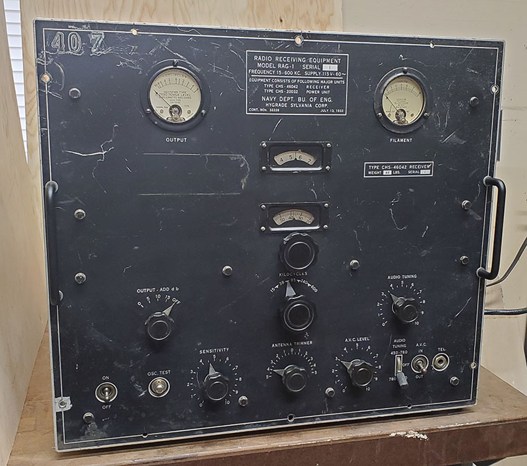
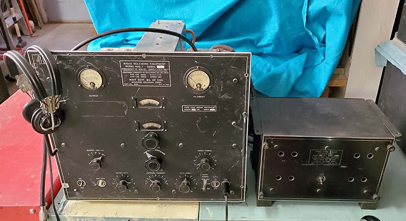
The RAG-1 was powered by a HP 712B power supply providing 6.5vac tube heaters, +180vdc B+ and -55vdc bias. The antenna was a 275' "T" wire antenna. Reproducers were 600Z ohm earphones.

Daytime Test Reception
:

VLF

NML - 25.2kc -  LaMoure, ND - Very strong signal  -  6.39 on RAG dial
NLK - 24.8kc  - Jim Creek, WA - Extremely strong signal  -  6.18 on RAG dial
NAA - 24.0kc - Cutler, ME - Strong signal  -  5.88 on RAG dial
NPM - 21.4kc - Lualualei, HI - Very strong signal  -  4.68 on RAG dial
NWC - 19.8kc -  Exmouth, Australia - very weak signal  -  3.86 on RAG dial

All of these USN VLF MSK stations are very strong signals that are easy to receive. NWC is a bit  more difficult but is still receivable. They are transmitting almost 24/7. Good reception of these stations in this particularly noisy region of the spectrum required the use of the AUDIO TUNING which greatly reduces noise and enhances a specific audio frequency that increases the MSK tones significantly above the noise. A really great feature of the RAG-1 for VLF reception. AVC was ON but set to about 5 which only limits very strong pulse-type noise. Tuning range 1, SENSITIVITY 2

LF

WWVB - 60kc - Ft. Collins, CO - Very strong signal  -  5.36 on RAG dial
JJY - 40kc - Mt. Otakadoya, Japan - Strong signal - 1.37 on RAG dial

WWVB is easy to receive anywhere in the USA at anytime. Again, AUDIO TUNING is able to really enhance the pulse encoded signal of WWVB while greatly reducing noise. Tuning range 2, SENSITIVITY 4. JJY 40kc (Japan's PE Time Station) requires listening mornings just before sunrise. Rcv'd 0545 hrs May 28, 2020. JJY ID in Morse CW 15min and 45min after each hour.

MW

MOG 404kc NDB - Montegue, CA   -   5.64 on RAG dial

Daytime reception of MOG is difficult but the moderately weak strength signal was easily heard

MW          Night Test Reception:  May 26, 2020  2150hrs to 2215hrs PDT  
 

       NDB STATION-FREQ-QTH           RAG DIAL

1. MOG 404kc - Montegue, CA -        5.64  ES
2. QQ 400kc - COMOX, BC, CAN -   5.59  
3. ULS 395kc - Ulysses, KS -              5.51  
4. PNA 392kc - Pinedale, WY -          5.42   
5. YWB 389kc - West Bank, BC, CAN - 5.32
6. QV 385kc - Yorktown, SK, CAN -     5.23
7. CNP 383kc - Chappell, NE -             5.20
8. OEL 381kc - Oakley, KS -                5.13
9. GC 380kc - Gillette, WY -                5.08
10. EX 374kc - Kelowna, BC, CAN -   4.97
11. ZP 367kc - Queen Charlotte Is, BC, CAN - 4.79  ES
12. AA 365kc - Fargo, ND -                  4.74
13. 6T 362kc - Foremost, AB, CAN -    4.66
14. NY 350kc - Enderby, BC, CAN -     4.33  ES
15. XX 344kc - Abbotsford, BC, CAN - 4.17 ES
16. RYN 338kc - Tucson, AZ -                3.98
17. DC 326kc - Princeton, BC, CAN -     3.62  ES
18. MA 326kc - Midland, TX -                3.62
 

Condx: Quiet, occasional crashes, no wind, no weather fronts. Best reception for NDBs was with the AUDIO TUNING OFF, AVC ON and set to 3 for the occasional crashes heard, Tuning Range 4, SENSITIVITY on 9.

18 NDB stations tuned in about 25 minutes. Stations marked "ES" were extremely strong. All others were average signal strength and easy copy. Best DX was probably QV 385kc in Saskatchewan and in the USA probably AA 365kc Fargo, ND or MA 326kc Midland, TX. Late May isn't the best time for MW DXing but the RAG-1 performed quite well. I only tuned about 75kc of the MW spectrum, that is, from about 325kc up to about 400kc. NDBs can be found from 195kc up to about 425kc with a few around 515kc to 525kc. Listening at night between the Autumnal Equinox and the Vernal Equinox results in much better reception conditions but, for late-May, the RAG-1 did quite well.

AM-BC - Although many AM stations can be tuned on the RAG-1, its very restricted audio renders voice transmissions almost incomprehensible and music almost unlistenable. Additionally, the BFO is always ON. Tuning in AM stations is only for testing purposes.


Power Unit   Type CHS-20032   SN: 16A

Since the Power Unit CHS-20032 is part of the RAG-1/RAH-1 equipment, there's absolutely no documentation for this unit. No schematic, no component layouts,...nothing. However, since I know what's required to operate the RAG-1, I should know what to expect. As far as the Power Unit design,...it's not exactly a standard power supply circuit. There's a 7.5K WW resistor inside the power supply acting as a load connected from B+ to B- when RAG-1 is selected. This allows the proper B+ and C- voltages to result if the RAG-1 presents the proper "load" on both of those circuits to the CHS-20032. The original rubber jacketed cables were included with this Power Unit and after removal of a minor modification, all of the wiring appears original.

After about three and a half years since completing the RAG-1, a CHS-20032 was purchased, thanks to Andy KD6TKX, who spotted the listing on eBay. The price of the Power Unit was very reasonable but the shipping was "a killer" not that the CHS-20032 is heavy,...it only weighs a little over 30 pounds but shipping rates keep increasing all the time. The Power Unit did arrive undamaged and in very nice, almost original condition.

Design and Construction - This Power Unit shows "Part of RAH-1 Equipment" on the front panel nomenclature. However, there is a "link-type" selector for either RAG-1 or RAH-1 so that the Power Units can be used for either receiver (if one of the two Power Units failed and that associated receiver had to be operational, the Power Units could be switched to power the "needed" receiver.) The circuit is a standard dual-section filtered power supply. However, since a negative bias voltage is required for the receivers and the designers wanted to keep the power supply components to a minimum, the CT of the power transformer isn't tied to ground. Instead a large 7.5K ohm WW resistor is connected as a R-load between B+ and B-,...this was probably to keep the voltages stable while operating the receiver. When the RAH-1 position is selected, the 7.5K is out of the circuit and that implies that the RAH-1 must have had other voltage and current requirements.

The rectifier tube is a type-80. The filter inductors are dual chokes in one housing. The filter capacitors are three 4uf oil-filled types in one large metal container with four terminals on top. The entire chassis and front panel are made out of aluminum. The cabinet is black wrinkle finished steel. The mounting flanges can be installed at the top of the cabinet for mounting the power supply under a table. Or, the flanges can be mounted at the bottom of the cabinet to allow securing the cabinet to a table top. Once installed, the power supply and receiver were turned ON or OFF by the Remote Control Unit. There aren't any vent holes on top of the cabinet. Instead the vent holes are in the front panel and in the back of the cabinet.


CHS-20032 Power Unit "as received" with resistor-bracket mod

Power Transformer Pin Out

1 - 2 - 3  =    6.3vac - CT - 6.3vac
4 - 5       =    5.0vac - 5.0vac
6 - 7 - 8  =    HV - CT - HV
9 - 10 - 11 =  0 - 110vac - 120vac

Power Cables Terminals Out - 3 cables

Voltage Output Cable
A1 = 6.3vac fil
A2 = 6.3vac fil
A3 = -45vdc bias
A4 = +180vdc B+
A5 = Chassis-Gnd

Control Box - Remote AC Switch Cable
G1 = Remote AC Switch
G2 = Remote AC Switch

AC Line Voltage Input Cable
K1 = 115vac input
K2 = 115vac input

Oct 4, 2023 - Inspection - There were some three paper notes I found folded-up inside the Power Unit after taking it out of the cabinet. These notes indicated that someone had been trying to use the CHS-20032 to power up a BC-1004 (Hammarlund Super Pro SP-200X.) The note doesn't indicate whether it was a successful attempt. There were three non-original resistors added to the choke and several wires added to interconnect the resistors to the output cable. The power output cable had tags installed on each wire but it appears that the measurements were taken after the mod was incorporated. The paper notes also indicated using a 5Z3 as a rectifier but that isn't necessary for the RAG or the RAH (a type-80 was the original rectifier used.)  

This CHS-20032 has "a unit of the RAH-1" on the front panel identification but the designation and the contract are the same as for the RAG-1. Also, internally there is a moveable link to select either RAH-1 operation or RAG-1 operation, so the power units were interchangeable despite what the front panel indicates. The power cable connects to five screw terminals on the fiberboard output plate. These are marked with an "A" prefix followed by a number 1 through 5. The remote controller cable connected to the G1 and G2 terminals and these are connections that parallel the front panel AC ON switch of the power unit. AC input voltage cable was connected to K1 and K2 terminals and have inline fuses on each side of the AC input to the transformer. The chassis is somewhat difficult to remove from the cabinet due to the three cables that exit out the rear of the cabinet. These cables have to be pushed through associated grommets, then the chassis pulled out a little, push the cables through some more, pull the chassis out,...on and on until the chassis comes out. Even then unless the cables are pulled completely through the cabinet grommets, the cabinet stays close to the chassis.

The first thing noticed was the added aluminum bracket with a large fiberboard insulator with a set of terminals that had three 10 watt wire-wound resistors mounted with purple wire routed over to the original output terminal board. Luckily, none of the added wires were soldered anywhere. The ends were wrapped around cable spade lugs and then covered with black electrician's tape. It was easy to entirely remove this mod, which apparently was an attempt to use the CHS-20032 to power up a Hammarlund Super Pro. Further inspection seemed to indicate that the rest of the power unit was all original.

Component Testing - I measured the DC R of the power transformer terminals to determine their function and if the transformer windings were okay. The windings tested fine. Next, I disconnected the three of the four wires going to the terminals of the filter condenser. I measured no shorts and the value of each filter capacitor was 4uf, which would be typical for the time period. I then measured the dual choke and each choke measured 350 DC ohms which again would be as expected for the time and circuit. There's large wire wound resistor that is in the circuit if the power supply is set up for the RAG-1. The value is 7.5K ohms.


CHS-20032 Power Unit after clean-up and testing

Testing the Circuitry - The link-selection of "RAG-1" connects the 7.5K across the B+ to B- with no CT/B- connection to chassis-ground. This implies that there was a resistive divider that did connect the CT to chassis either external to the RAG-1 or inside the RAG-1. However, measurement of the bias line input on the RAG-1 doesn't indicate any type of divider resistance to chassis (and I don't remember encountering anything like a divider network while working on the RAG-1.) This is because when I was rebuilding the RAG-1, I didn't have any documentation to refer to. The Sensitivity pot had been removed from the RAG-1 and a volume control circuit installed in its place. When I rebuilt the bias part of the circuit, I assumed a fixed C bias level and the 25K value seemed reasonable since it wouldn't be too much of a current draw. Since I didn't know how the Power Unit worked at the time (no docs) I assumed that its output bias voltage was a fixed level, like a battery bias or a bias power supply. Now I know that's not the case and the bias voltage and the B+ level are highly dependent on the loads on each output. The load for the B+ is about 47mA if +180vdc is supplied. The problem is the bias line. Testing seems to show that the bias line must be referenced with a load to chassis-ground of about 1000 ohms. The 25K Sensitivity pot that I installed in the RAG-1 is much too high of a resistance to allow the correct loading to occur and, of course, the resulting voltages are not even close to correct.

The first test for the CHS-20032 is to simulate the RAG-1 load with resistors. The B+ requires 3800 ohms to ground to draw 47mA at +180vdc. Through substituting various -C loads, I determined that just under 1000 ohms results in about -45vdc bias voltage with about +160vdc B+ (with a little tweaking I can get +170vdc and -40vdc which seems to be the best achievable voltages,...well within 10% of spec. The level of AC line voltage also can change these voltages, so it's all a "balancing act" to get the CHS-20032 to work with the RAG-1.) The next test is to parallel the bias line from the RAG-1 receiver with a 1K resistor, connect the rest of the RAG-1 to the Power Unit and see if the CHS-20032 then presents close to the correct voltage levels. Once that seems to prove that the 25K Sensitivity pot is too high in resistance, then it can be replaced with a vintage 1000 ohm WW potentiometer. At -45vdc, 1000 ohm pot resistance set up as a voltage divider for adjustable bias (with virtually no current draw) will have about 45mA of current draw and dissipate 2 watts. >>>

>>>  Any "load" variations on these outputs can change the voltages but the bias line load doesn't change and the B+ only changes a few mA, so voltage fluctuations should be minor. Maybe it's coincidental but the current draw on the B+ is about 45mA and the current draw on the bias is also about 45mA (with a 1000 ohm Sensitivity potentiometer.) I think for the voltages to be close to the desired levels, the current draw on the B+ and the C- has to be somewhat equal. Also, for battery operation maybe this was deliberate and allowed a battery pack to be used that would have fairly equal depletion.

I couldn't find a suitable 1K WW pot that looked vintage in the "junk boxes." I ordered one off of eBay that is a Mallory 1K 4W wire wound which might also need to have a resistor added across the pot to bring the "load" to about 900 ohms for the best voltage results from the CHS-20032. Although I can accomplish the testing on the bench, the final test will be trying to power-up the RAG-1 with this Power Unit. I removed the bottom cover off of the RAG-1 to test the CT/bias line connection and it goes directly to the Sensitivity pot. This makes the most sense since any other type of connection would certainly complicate the "hook-up." 

More as further testing is accomplished,...

Clean-up - The chassis really wasn't that dirty, just loose dark grit that brushed out easily. I used a moderately stiff bristle brush to remove the dust and minor surface oxidation. I installed a "used-tests good" Type-80 rectifier tube. The terminals, nuts and lugs on the triple 4uf capacitor were taken apart and cleaned. The terminals on the output fiberboard were also cleaned. The front panel had a red grease pencil applied "check mark" that was easily removed with WD-40. There was some very light, illegible writing in yellow grease pencil that was also removed with the WD-40. After the WD-40 application, Glass Plus was used to clean and remove the WD-40 residue. I had to replace one grommet for the AC line out of the rear of the cabinet. 


Comparing the RAG-RAH and the RAK-RAL Receivers

Is it a coincidence that the RAK and RAL receivers have so many similarities to the RAG and the RAH receivers? The frequency coverage of each pair is exactly the same, which for the RAG and the RAK isn't surprising, but the RAH and the RAL both cover 300kc to 23 mc giving both pairs of receivers the same total frequency coverage of 15kc to 23mc. Then there's the use of a control box for the operator to be able to power the receivers and switch audio from one receiver to the other quickly (for guarding two frequencies simultaneously.) Then there's the dial layout that uses the same, a 0-100 dial and a 0-10 dial with a span of 100 on that dial incrementing the tens dial by one (but other receivers also have this same dial set up.) The RAK-RAL place the two dials side-by-side and that does make reading them easier than the RAG's separated-vertical arrangement. Both the RAG-RAH and the RAK-RAL have a Tuned Audio Filter circuit used to enhance the audio frequency tone of received CW signals. Both receivers have an audio bandpass filter (the RAL can switch out both filters, whether that was possible with the RAH is unknown.) The panel layout is similar in having two meters at each upper corner and having both meters monitoring the same parameters of operation, output in db and filament voltage. The overall physical size is similar although the RAG is actually about 2" taller. The performance of the RAG and the RAK is very similar even though the RAG is a TRF with tracking BFO and the RAK-RAL are TRF receivers with regenerative detectors. With so many similarities, why were the RAG-RAH only built on one contract while the RAK-RAL were built in at least eight versions on multiple contracts by three different contractors in a period of time spanning almost a decade?

It's obvious that a lot of input came from the Navy Department about the design and exactly what was needed for shipboard radio operation from both the RAG-RAH and the RAK-RAL. That certainly accounts for a lot of the similarities. However, good signal reception performance was just one facet of shipboard radio requirements. Durability and reliability were also necessary requirements for radio equipment and for radio operations at sea. When looking at the RAG-1 construction, it just doesn't look like it was built for a "life at sea." When comparing the RAG to the RAK with regard to robust construction, the RAG band switch is not particularly robust and is built from fiber contact boards and rotor arms that are held in place with fiberboard clamps. It works fine but it doesn't look like it could take a lot of abuse. Another problem might have been the Garolite shaft used in the plate-grid tuning condenser. Mine was broken in the RAG and the material, though solid and unbendable, is somewhat brittle and shatters fairly easily. The huge audio bandpass filter supports several very heavy solenoid coils on thin fiberboard mounts that can (and did) break easily. The RAK, on the other hand, is ruggedly built, the design of the chassis and components less likely to be damaged by rough handling. The RAK band switch has each ceramic section mechanically supported and each section can be adjusted for best alignment for the physical operation of the band switch. The RAK construction is made from many heavy-duty cast metal parts, sheet nickel-plated brass and heavy aluminum pieces compared to the RAG-1's almost exclusive use of aluminum sheet metal. Only one tuning condenser is used in the RAK and it's housed in a cast metal box. I'm sure the "stacked" dual tuning condenser used in the RAG must have caused problems as it aged and was exposed to the sea-air environment. So, was the Navy disappointed at the RAG's lack of heavy-duty, sea-worthy construction? Was its obsolescence the result of mechanical design and construction?

Another consideration is the RAH receiver compared to the RAL. The RAH used seven plug-in coil sets to change tuning ranges. The six idle coil sets must have required storage somewhere in the ship radio room. Although performance of the RAH isn't known, it's likely that the construction was similar to the RAG in that aluminum sheet metal was used for the majority of the assemblies. The plug-in coils eliminated the band switch issues but the TRF tuner might have been similar to the RAG in using an insulated rotor shaft for the TRF plate-grid coupler. It's probable that the new RAL receiver was viewed as an obviously modern, "band switching" design that was built onto a robust chassis with heavy-duty components. Did the RAH contribute to the Navy's overall RAG-RAH dissatisfaction?

There might have been another reason for the Navy preference of the RAK-RAL. It was a RCA design (with Navy input) and the pre-WWII contracts were from RCA. The Navy had a long history with RCA and probably preferred dealing with them. Hygrade Sylvania Corporation was mainly an incandescent lamp and radio tube company at the time (1933.) They were just beginning to build electronic equipment. Perhaps dealing with Sylvania as a radio equipment manufacturer (not vacuum tubes) had other problems such as scheduling, manufacturing methods, meeting due dates, etc., that didn't exist when dealing with RCA, a company that had years of experience building shipboard radio equipment.

Was the RAG-RAH just an early-thirties design that aged rapidly resulting in its obsolescence? If that were the case, isn't the RAK-RAL also a thirties design using an even older system of regenerative detection? RAG-1 SN:1 has radio tube "testing" tags showing that it was actively in use up to about 1939. The Navy was in the process of modernizing their radio gear for the impending war and robust reliability along with the ability to operate in the presence of other radio gear (and soon to include radar operations) was a real necessity. It seems likely that the stout, rugged mechanical design that was added to the "reliability through simplicity" electronic design of the RAK-RAL was what the Navy favored.


RAK-7
 

RAG-1


RAG-1 Wrap-up

June 1, 2020 - Some final touches - I found a set of grab handles that looked appropriate for the RAG-1. The handles I had purchased earlier required screw and nut mounting where as the original grab handles were mounted with 8-32 FH screws from the back side of the panel. These later grab handles mount as the originals did and are matte black finish which looks correct. I also changed the white pointer on the bandswitch knob to matte dark silver to match the other pointer knobs. I have the RAG-1 setting on four large rubber cushions. These were extras that were made for a RAK-7 receiver that I restored several years ago.


photo left: RAG-1 on June 1, 2020 showing left side and top. Note the new grab handles.


photo right
: RAG-1 on June 1, 2020 showing right side and top. This is the side that was "crunched" and the upper side panel is a recreation.

The RAG-1 is a surprisingly good performer and an excellent VLF, LF and MW receiver considering it was designed in 1933. I'm especially impressed with the AUDIO TUNING circuit and how it allows peaking received audio frequencies. This audio selectivity of this circuit makes all the difference in copying the VLF USN MSK stations with ease. Sure they're strong signals, but often, in most superhet receivers using IF bandwidth selectivity, they're impossible to separate,...something the RAG-1, with it audio selectivity, does with ease. I'm sure the majority of the RAG-1's use was copying NSS, when it was Navy Central in Annapolis and transmitting down on 17.8kc sending CW signals that were the official communications to Navy ships. Most of the time, for the Pacific Fleet, NSS was relayed by NPL 30.6kc, NPG 42.8kc or NPM 26.1kc (NPL and NPM were in California, NPM was at Pearl Harbor.) The RAG-1 does an excellent job in the VLF region. LF and MW could have also been used as many Navy operations used 100kc to 500kc for many different purposes. One thing about the RAG-1,...and it probably was one of the Navy requests,...it's easy to operate. No regeneration to adjust, no coupling controls, no dual controls for band switches or tuning dials. The RAG-1 is pretty much turn it on, adjust the SENSITIVITY for background noise, peak the ANTENNA TRIMMER and begin tuning in signals. Reception noise levels can be dealt with by using the AUDIO TUNING and static crashes can be taken care of with the AVC LEVEL. It's just an easy to operate, fine performing LW receiver. However, like a lot of Prima Donnas, the RAG-1 was a somewhat delicate instrument that didn't like rough handling. Though a great performer, the demands of a future wartime at-sea environment dictated the RAG-1's ultimate pre-WWII retirement.
Henry Rogers © May 2020


Return to Home/Index


Radio Boulevard
Western Historic Radio Museum

 Vintage Radio Communication Equipment Rebuilding & Restoration Articles,

 Vintage Radio History and WHRM Radio Photo Galleries

1909 - 1969

- 60 years of Radio Technology -


This website created and maintained by: Henry Rogers - Radio Boulevard, Western Historic Radio Museum © 1997/2023