|
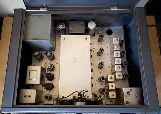
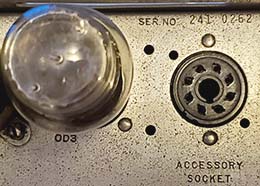
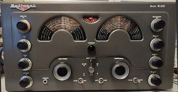
NC-183D Top of Chassis
SN: 430 0135
The first "three in a row" IF cans are for the 1720kc IF.
The first five of the "six in a row" IF cans are for the 455kc IF.
The rear-most can is for the Amplified AVC. Late production
NC-183D receivers will have a potted power transformer
identified as S461 as this receiver has. |
Other Details
- The NC-173, NC-183 and the NC-183D all featured a five-position
Crystal Filter that allowed for a wide range of adjustability
to the received bandwidth (from the normal IF passband
down to about 100hz selectivity.) The Crystal Filter was
also able to null heterodynes that were very common at a
time when all ham voice transmissions used the AM mode.
The Crystal Filter could also improve CW reception by
enhancing almost any selected heterodyne tone. To further aid IF
selectivity, three stages of IF amplification were used
in the NC-183D. National claimed that the NC-183D IF system provided
3.5kc passband
selectivity. This IF system was also employed in the
HRO-50-1 and HRO-60 for the same reasons. Good
selectivity was essential to cope with the congested ham
bands of the 1950s and 1960s and
to allow reliable communications. An 8 Z ohm and a 500 Z ohm audio outputs
were provided from an odd-ball three-pin socket on the
NC-183 (the NC-173 and the NC-183D used a standard three screw terminal strip.) The
three-pin mini-socket was probably replaced late in the
NC-183 production with a standard three screw
terminal strip. The Tone control only reduces the upper
audio frequency response leaving the lower end
unchanged. National indicated that the Tone control was
to improve reception for weak signals or noisy
conditions and not necessarily to enhance the audio
spectrum for listening pleasure (even though it does.)
Specifications indicated that with the Tone control at
10 the audio frequency response was 60hz to 12khz and
with the Tone control at 0 the audio frequency response
was 60hz to 1000hz. |
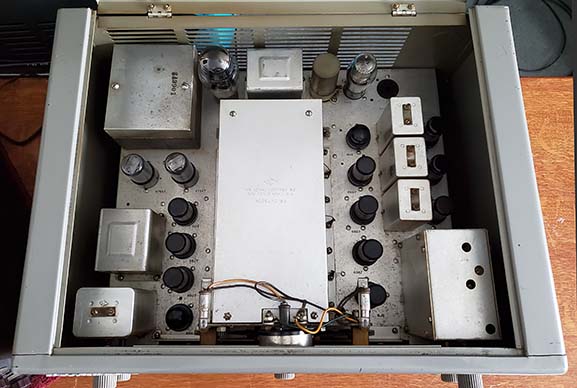
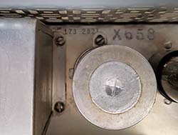
NC-183 Top of Chassis
SN: 241 0262
Behind the Crystal Filter are the two 455kc IF cans.
The rear-most LC (in
can) is for the amplified AVC. Note the numerous
WWII style metal-octal tubes. The power
transformer is the SA3901 used in the NC-183 and
in early NC-183D receivers. |
|
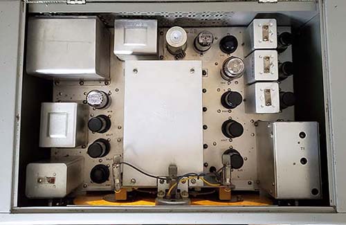
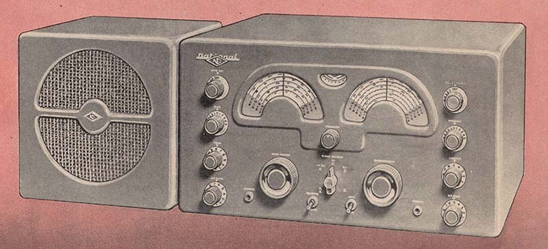
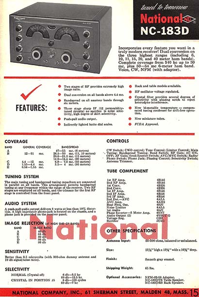
NC-173 Top of Chassis
SN: 173 2821
Note the different style power transformer that was
used on all NC-173 receivers. The pattern metal venting on
the back panel that was added by late-1947. Note how short the tuning condenser cover is compared to the NC-183. |
The Physical
- The cabinets on early examples of
the NC-183 and NC-173 were painted a light-gray color
that had a slightly silver undertone. This was a
semi-gloss, smooth-finish paint that was very durable
but had a tendency to show any nicks and scratches quite
well. The knobs used on these receivers had gray plastic knob
grips with bright silver skirts and the tuning knobs had
bright silver "knob-brights." The earliest
NC-173 and NC-183 builds had have vertically
oriented toggles switches as shown in early advertising.
Also, the earliest NC-173 didn't have an accessory
socket (the accessory socket was probably added by
late-1947 when the NBFM adapter became available.) Early examples
of the NC-183 had a punched pattern metal
screen spot-welded in place on the rear panel (see
photo right.) The earliest NC-173s (about the first
1000 receivers) had a solid back cabinet that didn't
have had any rear venting at all. Later NC-173 cabinets have
the patterned metal screen venting. By
1949, the NC-183 rear panels had horizontal-rectangular vents
that were punched into the sheet metal before cabinet assembly.
Probably around 1951 or so, the cabinet paint on the
NC-183 was changed to a dark gun metal silver-gray and
the knob grips were changed to black. During the last of the NC-183 production, in 1952, other
minor upgrades were beginning to
be incorporated into the receiver. The gunmetal
silver-gray color and black knobs were carried over to
the NC-183D cabinet introduced in late-1952.
Late versions of the NC-183D replaced the standard
SA3901 power transformer with a potted power
transformer identified as S461. The older style filter
choke was replaced with a potted filter choke identified
as S-669.
|
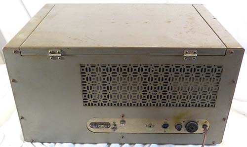
This is an Early NC-183
showing early style cabinet rear venting and
the lack of a "punch-out" hole for the Select-O-Ject
accessory. To the left of the fuse holder cap is
the three-pin speaker socket. Serial number is
202 0442 (built while the HRO-7 was still being
produced.) Interestingly, SN 202 1318 does have
the "punch-out" hole. Also, the first
1000 NC-173 receiver cabinets had no venting at
all.
photo from eBay |
|
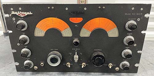
NC-183R Rack Mount Receiver
Version
The rack mount
version used a standard 19" front panel that wasn't an
integral part of the cabinet like the table models used.
The flat front panel allowed for engraved nomenclature
that was cut into the panel after the wrinkle finish
paint was applied. In this method, the nomenclature will
show the base metal, aluminum, through the paint as
"bright silver nomenclature" - well, when it was new anyway. Though
missing on this receiver, normally the rack mount
versions had a dust cover that protected the chassis.
Receiver pictured is ca: 1951-52
|
The NC-173 was a physically smaller receiver compared
to its bigger brothers measuring 20"W by 10"H by 12"D
and it also weighed at least ten pounds less. The NC-183
and the "D" were 20"x10"x15" with a weight of
approximately 65 lbs. Other Versions
- Like its predecessors, the NC-183D was also available
in a rack mount version designated the NC-183DR. The
earlier NC-183 had used a dark gray, almost black
wrinkle finish, panel but the NC-183DR used a gunmetal
gray smooth finish front panel. There was a military version
NC-183D, the NC-183MR that also had the military designation
R-651/URR-39. This receiver was installed in a 30" tall table rack
that included a matching rack mount speaker. The
complete
military-version receiver was designated as the AN/URR-39 and that
consisted of the R-651/URR-39 receiver, the LS-228/U
rack speaker and the MT-1529/U table rack (with shock
mounts.) This version
eliminated the 6M coverage and provided a LF
band (50kc to 150kc) instead. The band spread wasn't
calibrated for ham bands and just had a logging scale.
|
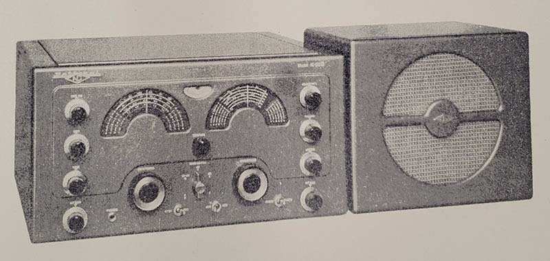
Artwork for the
NC-183D showing the yellow scale S-meter that
probably was never used in production |
|
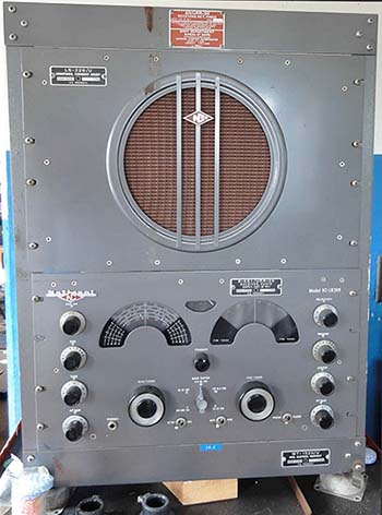
AN/URR-39 Receiver
photo from
navy-radio.com |
|
The NC-183D Legacy -
The production of the NC-183D ended in 1958. If there
was a continuation by National of the "big and heavy receiver with dual
dials separated by the S-meter" physical layout and
design, it would probably have to be the 1959 NC-400
receiver. Besides the similarity of the front panel, the
chassis also had a layout similar to the NC-183D. National
decided they would entirely update and redesign the NC-183D style
of the continuously available band spread type of
receiver and then add in a lot of military-type features
(some that required accessories) with the goal of producing
an exorbitantly over-priced equipment package. National
then tried to entice the military as
customers but the NC-400 was a cheaply-built
receiver with anemic audio and a litany of mechanical
issues due to the flimsy sheet metal used for the
construction of such a heavy receiver. The military
wasn't interested in purchasing another expensive receiver since
they already were buying the infinitely superior Collins-designed
R-390A receivers (even at over three times the cost of the
over-priced
NC-400, everybody loved the R-390A receivers.)
The hams weren't interested in the NC-400 either since the asking price
was nearly $900 without any accessories. When it came
right down to it, there wasn't anything about the NC-400
that could entice any of National's regular customers to purchase
the receiver. NC-400 production ended quickly with
only one run of less than 1000 receivers. The
NC-400, the NC-183D's successor, ended up being
purchased by a few big-budget commercial users and by
the U.S. tax-payer supported FBI where they were used as field-office receivers.
The NC-400 shown was originally sold to WHAS, a
commercial radio-TV station in Louisville, Kentucky, as a
monitor receiver for their tech department (luckily,
they seldom used it and never worked on it.) For
more details and a critical analysis of the quirky
multiple IF sections and the multitude of
mechanical
issues that plagued the NC-400
receiver you can go to the "National NC-400"
article on this website. Use the Home/Index link at the
bottom of this article for navigation. |
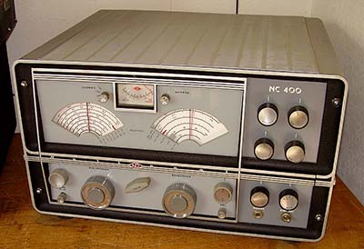
NC-400 SN: 543 0006
from 1959 |
|
Summary of
NC-173, NC-183 and NC-183D Receiver Features |
|
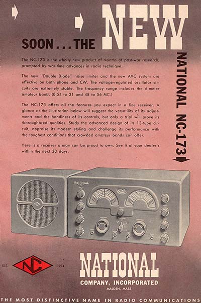
NC-173
Produced from 1947 to 1951
Orig.
Price - $199
Circuit - 1 RF Amplifier, 2 IF Amplifiers, 1 Audio
Output Amplifier
Tubes used: RF-6SG7,
Mix-6SA7, LO-6J5, IF-6SG7 (2), Det-6H6, AVC Amp-6AC7,
NL-6H6, BFO-6SJ7,1stAF-6SJ7, Audio Output-6V6, Rect-5Y3,
Reg-0D3
Audio Output Z - 8
ohms and 500 ohms from three-pin mini-socket
Tunes .54-31mc and
48-56mc
Antenna Input -
Three screw terminal strip, 300Z nom.
AM Sensitivity -
<2.0uv 6db s/n ratio (1948 catalog spec)
Selectivity
- ~8kc at -10db w/o Crystal Filter
|
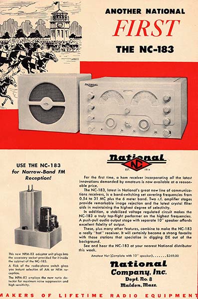
NC-183
Produced from 1948 to 1952
Orig.
Price - $269
Circuit - 2 RF
Amplifiers, 2 IF Amplifiers, P-P Audio Output
Tubes Used: RF-6SG7
(2), Mix-6SA7, LO-6J5, IF-6SG7 (2), Det-6H6, AVC
Amp-6AC7, NL-6H6, BFO-6SJ7, 1stAF-6SJ7, Phase Inv-6J5,
Push-Pull Audio Output-6V6 (2), Rect-5U4, Reg-0D3
Audio Output Z - 8
ohms and 500 ohms from three-pin mini-socket
Tunes - .54-31mc and
48-56mc
Antenna Input -
Three screw terminal strip, 300Z nom.
AM Sensitivity -
<1.5uv 6db s/n ratio (1948 catalog spec)
Selectivity - ~8kc
at -10db w/o
Crystal Filter
|
NC-183D
Produced from 1952 to 1958
Orig.
Price - $369.50
Circuit - 2 RF
Amplifiers, 3 IF Amplifiers, Double-Conversion, P-P
Audio Output
Tubes Used:
RF-6BA6(2), 1720kc Conv-6BE6, 455kc Conv-6BE6, IF-6BA6
(3), Det-6AL5, AVC Amp-6AH6, NL-6AL5, BFO-6SJ7, 1stAF-6SJ7, Phase
Inv and S-meter Amp-6SN7, Push-Pull Audio Output-6V6
(2), Rect-5U4, Reg-0B2
Audio Output Z - 8
ohms and 500 ohms from a three screw terminal strip
Tunes - .54-31mc and
48-56mc
Antenna Input -
Three screw terminal strip, 50 to 300Z nom.
AM Sensitivity - <3.5uv at 300Ω 10db s/n ratio
(1956 ARRL HB Ad spec)
Selectivity - 3.5kc at -6db w/o Crystal Filter
|
|
NC-173, NC-183 and NC-183D Serial Number Log
Serial numbers are very helpful for determining when
a particular receiver was built. The NC-173, NC-183 and
the NC-183D all use the standard post-WWII National
format of a seven digit serial number. It's fortunate
that National incorporated the specific "production run
number" as the first three digits of the serial number.
The production run numbers were assigned
chronologically. Each run produced a certain quantity of
receivers that were assigned a four digit number that
included "leading zeros" to identify specific receivers.
For example, HRO-5A1 serial number 184 0009 would be run #184
and this receiver was the 9th off the line. The serial numbers collected from later post-war HROs
and NC-2-40D receivers have already provided several
examples of the chronological issuing of many of the run
numbers. However, I really don't have anything specific to the
NC-173, NC-183 or the NC-183D. So, I'll start collecting
serial numbers on those types of receivers and see what
can be determined.
UPDATE: So far, it looks like ALL NC-173
receivers used #173 as the production run identification
and the four digit serial number provides the
chronological build-date information.
SN Locations:
The NC-173 serial number is usually stamped into the
metal chassis at the top-rear-center of the chassis just
above and between the filter choke and the filter
capacitor. The NC-183 serial number and the NC-183D
serial number are located above the accessory socket
and have "SER. NO." stamped
into the metal chassis (or silk-screened) proceeding the actual seven digit
number that is stamped into the metal chassis. The three photos
to the right show the locations of the
serial numbers for each receiver type.
Report Your SN:
If you have examples of these receivers, please e-mail
the serial number of each receiver. Be sure to
mention if your receiver is original and has any
significant differences from what's described in this
article or anything unique (and factory original)
about the receiver such as cabinet paint color used, cabinet
rear vent type, power transformer type on 183D, factory circuit changes,
etc. I'll add the serial numbers to the log and after a
while the log should produce
some interesting information. The variations tied to
serial numbers will help date when the changes happened. Here's an e-mail link
below or just use the e-mail link on website Home Page
(both links are the same e-mail address.)
Send your NC-173, NC-183 or NC-183D serial number to:
Serial Numbers
173-183, National, WHRM |
NC-173:
173 0212(vots,nas,SBC), 173 0912(vots, nas,SBC), 173 2155, 173 2821(pmrv), 173 4204(pmrv),
NC-183:
202 0248, 202 0442(eB,pmrv), 202 1318(pmrv), 241 0128, 241 0262, 241 0377,
305 1423(T), 309
0159(R),
309 0368(R),
309 0785,
NC-183D:
328 0584(ST,sM), 357 0271(NOT), 357 0363, 357 0668(ST,PS-J), 372 0538(PT), 372 0574(PT),
396 0086(PT,PS-J), 430 0135(PT), 430
0174, 430
0478 (R, Black Wrinkle panel)
R= Rack Mount
PS-J = Parts Set that was Junked
ST= standard pwr transformer SA3901 (on NC-183D)
PT = potted pwr
transformer S461 (on NC-183D)
NOT = Non-original pwr transformer
eB = seen on eBay
sM = seen at swap meet
pmrv = pattern metal rear vent
vots = vertically oriented toggle switches
nas = no accessory socket
SBC = solid back cabinet (NC-173)
If no notations are shown then just the serial number
was reported
|
|
Receiver
General Information |
|
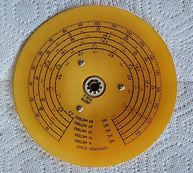
NC-173 and
NC-183 dials are a plastic disk that is riveted to the metal hub.
This type of material will darken as it ages and with
its long-term exposure to light and heat. The NC-173 and
the NC-183 used the exact same dials. |
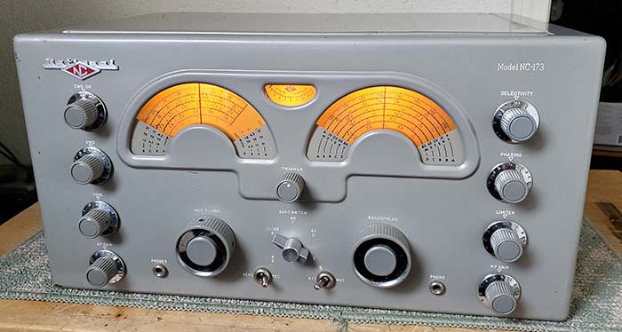
NC-173 & NC-183 Yellow Phenolic-Acetate Dials versus the NC-183D
Lucite Dials
- The NC-173 and the NC-183 used acetate-based phenolic plastic
dials that were pale yellow when new but nearly all of
these types of dials have darken considerably to an
amber-color due to the photosensitive nature of the type
of plastic. These dials along with the S-meter scale
were backlit resulting in one source of intense light
near the dials as long as the receiver was on. Bright
sunlight directly on the dials also contributed to
intense darkening of the dials. There were also
indications that age and possibly heat from the receiver (if operated for long hours)
also contributed to this darkening.
The NC-183D addressed this dial material problem by
using copper metal-backing plates that had a Lucite dial
riveted to the front of the metal plate (Lucite is a
high quality-type of crystal-clear Acrylic that won't
yellow or crack and is very strong but lightweight.) The Lucite was
reverse-side silk-screened with the dial nomenclature. This gave the dial
scale the appearance of "depth." These dials had to be illuminated from the
perimeter edge with the lamplight going through the
Lucite which makes the
silk-screened numbers very bright and visible (it requires the
position of the lamp be as far forward as possible for optimum illumination.)
Since Lucite was used the NC-183D dials, they are almost always in excellent condition (something
that, unfortunately, can't be said for the NC-173 and
NC-183 dials.) Dirt, debris and staining can get
behind the Lucite if the dial is subjected to a very
humid or wet environment. Extreme moisture behind the
dial will deteriorate the silk-screened nomenclature
causing it to crack and flake resulting in partially
missing numbers and tiny flecks of white silk-screen
paint.
NOTE:
As a restoration hint,...the dials from the NC-173 and
the NC-183 are identical with the same part numbers so
they can be interchanged if necessary.
NOTE 2:
It's interesting that while the NC-173 and NC-183 Band
Spread dials don't have the 15 meter band, the Main
Tuning dial does have 21.0mc to 21.5mc highlighted as an
amateur band. Although the IARU had approved a 15M band
and it was known that a ham band was going to be created
in and around 21mc starting around 1946, it wasn't an
officially usable ham band until 1950. Late in NC-183
production (and probably NC-173 production) the
bandspread dial was changed to have 15M calibration. Notice that the
NC-183D Band Spread dial shown to the right does have
the 15M band calibration (actually, 19.8mc to 21.56mc.)
|
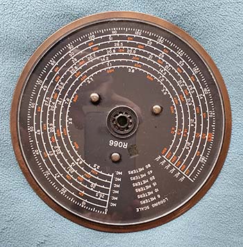
NC-183D dial
showing the metal rim of the copper-plated backing plate and the
Lucite front dial. Lucite was used for airplane cockpit
covers and aircraft windows because of its strength and it will not yellow or crack with exposure
to UV or weather. |
|
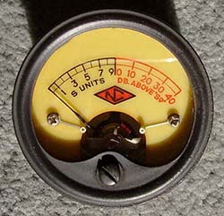
This Marion
Electric meter is actually for a National NC-100 Series
receiver but it's the same phenolic material that was
used in NC-173 and NC-183 receiver dials. |
NC-183D
S-Meter - The S-meter
scale was changed for the NC-183D to a black field with linear scale
and numbers that were translucent yellowish-orange up to S-9 and
translucent red for DB above S-9 when backlit. These type of S-meters also seem to age quite well
(most of the time.) While the "red" on the
NC-183D S-meter for the <NC> and "over S-9" was "bright red" when illuminated, the "red"
used on the Lucite dials was a "brick red" color.
Original NC-173/NC-183
Dial Color - The S-meter shown to the left
is a NOS example that has been kept inside a box and
has never been exposed to sunlight, illumination lamps
or heat. It shows the correct color that the
acetate-based phenolic dials were when new. The red
numbers and letters show how vibrant the red was when
new.
Reproduction Dials and
S-meter Scale - Radio Daze, the major
supplier of reproduction plastic dials, in their online
catalog show that they offer reproduction dials for the
NC-173/NC-183 (same dials) and also for the S-meter
scale. But, before ordering, I would contact them to be
sure that the material they are using to make the dials
is the light yellow color shown in their online depictions.
A few years ago, I ordered a RCA ACR-136 repro dial that
was shown as the correct light yellow material online but what was
delivered was a dark reddish-brown material that was as dark
as the darkened dial I was trying to replace. According to
Radio Daze, the reason for the dark color was that was
the only phenolic material available (at that time,...2021.) Since the cost
for the NC-173/183 repros is over $70 (the complete set of
two repro dials is $47 and
meter scale is $24) I'd check with Radio Daze prior to ordering
to confirm what color material is going to be used. Be sure to also
realize that you'll only receive the plastic repro dials.
You have to remove the old dial from the hub and mount
the new repro dial on the old hub. You don't need to use
rivet mounting (as original) since there's a lot of
clearance for screw and nut mounting. Also note, Radio
Daze has a six week
lead time for delivering repro dials (they blamed
COVID in 2021, I don't know what the problem is now.)
|
| Analog Dial Accuracy - As for the dial accuracy, it's fairly good considering that it's an analog dial
that's electronically coupled with bandspread tuning with both dials having
limited resolution. By using either received known "marker" frequencies or an
external crystal calibrator reasonable
dial accuracy for the ham bandspread tuning can easily be achieved. Many
hams in the 1950s had surplus heterodyne frequency
meters like the BC-221 or they had a device called a Frequency Standard
that was a crystal oscillator for 1000kc, 100kc and then
a multi-vibrator circuit for 10kc. At the time, most
manufacturers felt that the vague frequency accuracy of
the receiver's tuning dial was normal considering it was
an amateur receiver and extreme accuracy could always be
provided externally with the operator using a frequency
meter or similar device and then using the logging
scales provided for accurate frequency resetting. |
|
There's Only One Accessory Socket
- Only one accessory socket was provided for either the optional NBFM adapter or for the optional
National Select-O-Ject (not both, and not for a National Co. plug-in Crystal Calibrator.)
The earliest versions of the NC-173 didn't have any accessory
socket. The accessory socket was probably added when the NBFM
adapters became available around August 1947.
The Select-O-Ject - SOJ-2, SOJ-3
- This accessory was connected to the NC-173, NC-183 or NC-183D accessory socket via a
cable with plug connector on the end from the Select-O-Ject for
power and routing of the signal lines. The SOJ-2 was
the version that had to be used with the NC-173, NC-183. There was a
"punch-out" hole in the rear cabinet panel to provide access to the
accessory socket for the SOJ-2 cable (the "punch-out" wasn't on the
earliest 1947
NC-183 models, but was added by SN 202 1318, and the NC-173 didn't need the "punch-out" because it had the accessory socket on the rear
chassis apron.) The NC-183
accessory socket had to be rewired to work with the SOJ-2 (per
the National instructions but one would think it would be more
prudent and easier to purchase the SOJ-01 version the came without a
plug wired to the cable allowing the user to add a plug wired for
his particular receiver) and the
Radio/Phono switch on the receiver was used to place the SOJ-2 into
operation (the NC-173 had to have a "dummy" phone plug inserted
into the front panel PHONO jack since it didn't have a Radio/Phono
switch on the front panel.) The NC-183D used the SOJ-3 that didn't require the
accessory socket be rewired. The NC-173 also didn't require
accessory socket modification to work with the SOJ-2. As mentioned,
the SOJ-1 came without a plug installed to allow it to be adapted to
any receiver (instructions included.) The Select-O-Ject was a tunable audio frequency
peaking or nulling circuit usable mostly for CW but able to enhance
other types of signals also. Nowadays,
Select-O-Jects seem to be in the "seldom-seen" category of National
accessories but, perhaps that's because the current owners just don't want to part with
a versatile and usable device like the Select-O-Ject.
|
NBFM Adapter - NFM-73, NFM-83
-
Starting in the late-1940s and going through most of the 1950s, Narrowband FM was
thought of as a practical solution to the ever-growing problems of AM TVI and also for
RFI-QRN
reception problems in some locations. Since FM eliminated the
amplitude variations of the signal that caused most of the TVI
issues and replaced the amplitude variations with frequency variations that seemed
invisible to TV watchers, NBFM seemed perfect for Voice
communications for hams. The problem was that NBFM took up just
about the same bandwidth, maybe a little more depending on the
modulation f-deviation, as the standard AM signal. So, although TVI and
QRN issues might be gone, there was the possibility that the HF ham
bands couldn't accommodate a lot of NBFM users in competition with
the AM users. As a result, the FCC decided to gather some data on
NBFM in the HF amateur bands. For a period of one year starting in
late-1947, NBFM was
allowed anywhere in the normal HF amateur phone bands. All of the
manufacturers knew this and responded by introducing adapters and
NBFM capabilities in their gear produced in 1947 and 1948. At the
end of one year (about the end of 1948,) the FCC determined that
NBFM was going to have negative impacts on ham phone operation on
160M, 80M, 40M and 20M and operation of NBFM was not going to be
allowed on those bands. The FCC allowed for
limited the operation of NBFM to frequencies above 27mc, relegating
NBFM to 11M and 10M ham bands below 30mc. Though several manufacturers offered a NBFM
function on their receivers, it never became a popular mode of
transmission below 30mc. This was partially because of the
transmitting frequency limitations imposed by FCC regulations that
prevented wide-spread use of NBFM in the HF region of the spectrum. However later on, NBFM did become the popular voice
mode on VHF, especially on the 2M band. Currently, NBFM on HF is authorized
for 29.2mc to 29.3mc in the 10 meter band and this small portion of
the spectrum is the only HF authorization for NBFM communications. When the NFM-83 adapter is installed into
the Accessory socket, the adapter receives its operational voltages from the
receiver. Two tubes are used in the adapter, a 6SK7 IF amplifier and a 6H6
discriminator/detector. The
signal input is from the IF output and AVC line via the Accessory socket and the
NFM-83 output is
via the Accessory socket to the receiver's audio input. The NFM-83 is essentially "in
operation" whenever the receiver is turned on but the output utilizes
the PHONO-RADIO switch to route the NFM-83 output to the receiver's audio
system. When installed, PHONO is used for NBFM operation and RADIO is used for
normal receiver operation. The NFM-73 has a different configuration
that allows it to be plugged into the NC-173 accessory socket that's
on the rear chassis apron on the back of the receiver. The NC-173 didn't have a PHONO-RADIO
switch so a dummy phone plug was inserted into the PHONO input on
the front panel to actuate the jack-switch which then disconnected
the AM detector and routed the NFM-73 output to the audio amplifier
stages. Withdrawing the dummy plug returned the NC-173
to AM-CW reception. No modifications to the receiver were required
for using the NFM-73 adapter. The NFM-73 and NFM-83 are fairly easy
to find. Either of the adapters are
usually cheap and they should be since they are completely useless devices nowadays. |
NFM-83
Narrowband FM Adapter
Is it really a useless device?
Since NBFM on HF is only authorized on
29.2-29.3mc, finding any HF-FM activity today
would be a challenge. |
Kit-type 100kc Crystal Calibrator
- I don't know of any reason that National didn't provide for using
their
onboard Crystal Calibrator other than economics. Certainly, had
National included their typical 1000kc/100kc plug-in calibrator,
that would have been the most useful of the commonly available
National plug-in accessories but it would have required additional
wiring for an additional accessory socket and front panel switching
to operate the calibrator switching from the front panel of the receiver.
That's why the HRO-50/60 receivers have two accessory sockets - to
allow using a Crystal Calibrator with front panel switching plus either the NBFM adapter or the
Select-O-Ject that were operated with a separate rotary mode switch
for FM and the panel switch for the Select-O-Ject for its operation.
On the NC-183 series, since the dial indexes are not movable, the
calibrator could be used to set-up the Band Spread dial accurately
by minor adjustment of the Main Tuning. Conversely, the Main Tuning
dial could be set up accurately using minor adjustment the Band
Spread tuning.
Since regulated +150vdc and 6.3vac are available at
the NC-183 or NC-183D (or even the NC-173) accessory socket, any
100kc crystal calibrator kit could be built to use the accessory
socket of the receiver. Generally these kits will have a toggle
switch on the calibrator to turn off the B+. The output can usually just
be electrostatically coupled to the antenna
input and provide sufficient signal level. The hassle is that the lid of the receiver has to be lifted
to turn the calibrator on or off or, for the NC-173, one would have
to reach around
behind the receiver to turn the calibrator on or off. National, along with
most of the other receiver manufacturers, certainly
thought that any ham would have had either a surplus Heterodyne Frequency
Meter
or a ham Frequency Standard (an external, self-contained crystal
oscillator providing 1000kc, 100kc and 10kc markers) for accurate frequency
measurement of a received signal or for determining ham band edges
so an "onboard" 100kc crystal calibrator wasn't considered
a necessity. Additionally, the logging scale provided on each dial
is 0-200 and that provided a lot of resolution for accurate
resetting to known "logged" frequencies. Using any sort of
calibrated signal source (a borrowed Frequency Meter, for instance)
it would have been possible for a ham to "log" all of the ham band
edges and any specific ham schedule frequencies using the Main
Tuning Log setting and the Band Spread Log setting. This was an easy
and convenient method for accurate frequency reset that didn't
require an on-board Crystal Calibrator. As an example, on my NC-183
receiver, the Nevada Vintage Mil-Rad Net on 3.974mc is tuned by
setting the Main Tuning to Log 168.0 and the Band Spread to Log
170.5. It's a quick setting of the two dials and the receiver is "on
frequency."
|
|
Phono Input
-
Although the Phono circuitry was used via the accessory socket
wiring (pin out for audio varies with model) for the Select-O-Ject output or the NBFM adapter
output,
the Phono jack input could be used for any other sort of audio
amplification as long as the input levels and the impedances
matched. The SOJ-2 had to be disconnected to use the Phono input for a phonograph
cartridge input. The National NBFM adapter instructions don't
indicate that the adapter had to be removed from the accessory
socket to use the Phono input, but it did.
Battery Operation -
The octal socket on the rear chassis
apron allows access to the power supply voltages, remote standby
functions and can allow a
hook-up for battery operation of the receiver. Remote standby was
later routed to its own three screw terminal strip on the NC-183D.
As for battery operation, one famous use of a
NC-173 operated entirely on dry cell batteries was the receiver used
on the Kon-tiki Expedition in 1947. National advertising promoted
this trans-Pacific experimental raft sailing from South America to
Polynesia and its use of the NC-173 in several ads at the time.
Several battery and crank-generator small transmitters were also
used on the Kon-tiki. National advertising in the September 1947 QST
issue implies (but doesn't specifically state) that the Kon-tiki also carried a National HRO-7
receiver that was also dry-cell battery operated, however the
official write-up in Dec. 1947 QST states that the NC-173 was the
main receiver and the HRO-7 isn't even mentioned. It seems unlikely
that the HRO-7 was aboard since it wasn't introduced until August
1947.
|
|
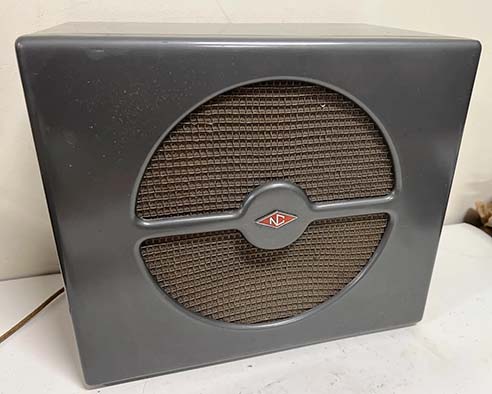
NC-183DTS 10" diameter
PM Loudspeaker for
the NC-183D
The NC-183TS was exactly like the "DTS"
but with the light-gray paint to match the NC-183. The
same brown woven cloth was used in the early version
loudspeakers. Be aware that some eBay sellers will
measure the cabinet dimensions and list the smaller MCR
6" speaker as a "National 10 inch Speaker" (this is
actually quite common.) |
Loudspeakers - The
NC-183 used a 10" diameter PM loudspeaker, identified as the NC-183TS, in a matching table cabinet. The
1948 National Catalog shows that the
NC-183 was
supplied with the 10" loudspeaker however they are seldom found together
nowadays. Even though National specified that the loudspeaker was
included with the receiver, many dealers would offer the receivers
at a reduced price but minus the loudspeaker and then list the
matching loudspeaker for $10 to $14 extra. The 1950 ARRL HB advertisement
for the NC-183 indicates the loudspeaker wasn't
included in the price shown ($14 was the price.) The
loudspeaker impedance was 8Z ohms nominal. There also was a smaller
version of this loudspeaker cabinet that used a six-inch speaker in a light-gray enclosure was
designated NC-173TS. There are other light-gray smaller speakers
that are found equipped with eight-inch speakers
but these were intended for the HRO-7T. The 1947 National catalog states that the
NC-173 loudspeaker wasn't included with the receiver
and was priced at $10. All NC-173 advertising doesn't mention that
the speaker wasn't included with the receiver, even
the early ads in QST. The smaller loudspeaker
was intended for the NC-173 since its audio
output capabilities were primarily for ham communication (although
these smaller speakers do sound much better than
would be expected.)
The NC-183D was supplied with the larger 10" diameter PM loudspeaker and
cabinet. The speaker enclosure paint
color was changed to the gunmetal silver gray that was used on the
NC-183D receiver cabinet. The three-pin plug that had been used on
the NC-183TS was replaced with two
spade lugs to match the NC-183D screw terminals for the audio
output. There's usually a paper string tag on the speaker cord
indicating that it should be connected to the 8
ohm terminals of the receiver. This "DTS" version of the loudspeaker is shown in the photo to the
left. The NC-183D manual back page shows the speaker as model
NC-183DTS. The 10" loudspeaker does have good bass response
and sounds very nice for quality SW-BC reception (but don't have
the speaker only two feet away and directly in front of you. The speaker will sound much better from across the room,...ten
feet, or so,...in my
opinion, this applies to almost all loudspeakers.) |
|
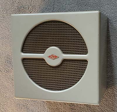
NC-173TS 6" diameter PM
Loudspeaker for the NC-173
Although the assumption would be that an
8" loudspeaker would be installed into this size
cabinet, I've only seen 6" diameter loudspeakers
installed. If these smaller cabinets are found with an
eight-inch speaker installed it was intended for use
with the HRO-7T. The cabinet color is
the light grey with a slightly silver tint. |
|
Cabinet Paint
- The cosmetic department always seems to be problematic
at best. The light gray-slightly silvery paint job on
the NC-173 and NC-183 or the darker gunmetal gray-silver
paint on the "D" were actually
very durable paints but this type of smooth semi-gloss finish paint
always seems to show the "hits"
that the cabinet has taken from just about anything setting on top of
or next to the receiver or whenever it's moved from one place to
another. Part of the problem is that the NC-183 versions
are heavy receivers with "absolutely nothing" to grip
when trying to carry the receiver when moving it to a
new
location. I'm sure a lot of the dents
and scratches are due to the mover dropping the receiver
or the receiver just "slipping" out of the mover's hands.
The upshot is it's almost impossible to find
any of these receiver-types in mint
cosmetic shape. The nomenclature is stamped into the metal so a
repaint might be possible although only
automobile-quality paint that is "custom matched" to the original
color
should be used in any repaint. Almost all "off the shelf" spray-can paint will
contain fillers that act as a sort of primer but using
this type of paint will fill up the debossed
nomenclature. The original paint was very durable but
was very thinly applied
and that's why it seems so prone to damage. If
at all possible avoid repainting the cabinet
since properly mixed paint, special equipment,
correct prep and especially professional spray
areas and professional painting experience are
all necessary for a quality result. Often, if
the receiver has decent cosmetics, a good
thorough cleaning followed by a careful
"touch-up" paint application is all that's
necessary to get the receiver looking acceptable
for a vintage ham station.
NOTE: Shown to the right is an excellent
repaint of the gun metal dark gray used on the
NC-183D. The paint application looks like
power-coating but it's completely even and
looks almost original (just slightly darker gray color.) The filled
engraving looks
excellent. So, quality repaint jobs are possible but it
almost certainly involves professional painters using
quality paint and equipment with the paint job done in a
controlled environment. |
NC-183D - A Quality
Repaint Job
photo from eBay
|
Cleaning
Phenolic Dials on the NC-173 and NC-183 - As mentioned, the acetate-based phenolic plastic dials used on the NC-173 and
NC-183 are always much darker nowadays than they were when new.
Most of the time, the section of dial that was exposed to light
through the front panel dial opening will be much darker than
the unexposed areas. This darkening is inside the plastic
material and is impossible to correct. Sometimes a slight
improvement can result with damp-cleaning the back-side of the
dial. Any cleaning of the front-side of the dial should only be
attempted after a test-cleaning of the part number
that's located near the hub of the dial. If the part
number isn't affected by damp-cleaning then the entire
dial front can be cleaned by that method. I've found
that many plastic dials made after WWII will have very
durable ink that can be damp-cleaned, BUT TEST TO BE
SURE. The NC-183/173 dials used very durable ink on the dials
and they can be cleaned directly using a Glass Plus
dampened paper towel. DON'T EVER USE WINDEX, the ammonia
is a harsh cleaner, use only Glass Plus, don't scrub, don't use a lot of
pressure and watch the ink for any thinning. I didn't
have any ink degrading with Glass Plus when
damp-cleaning either the NC-183 dials or the NC-173
dials yet years of dirt and
tobacco staining were removed. After the cleaning, the dial
will have a "flat" look but lightly polishing with a
dry soft flannel cloth
will impart a sheen to the plastic dial without doing any
damage. This dial cleaning won't change the darkening that has
happened because of sunlight. That discoloration is deep inside the plastic
material. What the cleaning does is remove other types of dirt
on the surface of the dials and that will generally brighten the
dial somewhat and increase the contrast between the dial color
and the nomenclature. Cigarette smoke contamination on the phenolic-acetate
dials is the most common "dirt" that can usually be easily
removed on post-WWII dials, but be sure to test the silk-screened ink on a
non-visible area first.
Cleaning Lucite Dials on
NC-183D - Lucite can be cleaned using
Glass Plus or a plastic foam cleaner. Don't use WINDEX.
I've used Glass Plus with paper towels and had no
scratching occur but some plastic cleaners will suggest
using a soft cotton cloth to avoid scratching. It
probably depends on the paper towel brand used. Avoid
the cheap paper towels that are coarse and stiff
feeling. The most important part of cleaning is to NOT
use WET paper towels or cloths. The excess wetness will
wick down the rivet holes and get behind the Lucite.
Normally, this will dry and not cause any problems but
if there is any dust or a film coating on the inside of
the Lucite dial, then it's possible that some residual
pattern will show in the dust after the wetness has
dried. It's not staining but you can't get rid of it
unless you disassemble the dial which means drilling out
the rivets. That's a major pain that's best avoided by
only using slightly damp paper towels or cloths. Other
than avoiding excessively wet cleaning, the Lucite dials
are very forgiving and easy to clean.
NOTE: If
a little moisture did wick down the rivet holes usually the
"stain" won't show when the entire receiver is assembled
since the rivets are hidden by the shape of the dial
openings in the front panel.
Dial Covers
- The dial cover on the NC-173 and the NC-183 is a
single, thin plastic, rectangular piece that has the
band indicators for both dials applied on the backside
and then covered with gray paint for color and
protection. This piece can and easily does get very
dirty. That adversely affects the dial visibility. The
dial cover plastic is mounted with two aluminum
strip spacers, one on each side. The aluminum strips are
only used on the NC-183 to provide
the proper spacing so the dial cover is the correct
height behind the front panel dial openings. There are two screws,
lock washers and nuts on each side to mount the plastic
piece. The screw heads are on the outside of the front
panel. On the inside is the aluminum strip, then the
plastic, then the lock washer and nut. The nuts aren't
overly tight or the plastic could possibly crack over
time. Once the dial cover is dismounted, it can be
easily cleaned with Glass Plus. Both sides need to be
clean. Usually the gray paint that covers the
nomenclature is in good condition. If it has scratches
or missing paint areas and the lettering isn't affected
then carefully match the paint and apply on the
backside. Remount using the original spacers and
hardware. The NC-173 dial cover mounts the same way but
without any aluminum spacers. Since the front panel's
embossed area is just around the dials and the mounting
screws for the dial cover are in the area of the panel
outside the embossed area, the dial cover ends up being
flush with the inside of the dial openings with no
spacers. The NC-183D uses two Lucite dial
windows that are approximately 0.125" thick and have a
section that has a black background paint applied. The
index line is an engraved line on the interior side
filled with white paint. The mounting edge of each piece
is slotted so the mounting screws only have to be
loosened. The Lucite windows both mount just on one side
with an aluminum spacer and another aluminum strip that has
tapped holes. The side nearest the S-meter isn't
supported except for a metal support guide that is
mounted by way of the Trimmer shaft bearing bracket. The slotted mounting on one side only will
allow for slight position adjustments. The band
indicators are on the exterior side of the Lucite
with engraved nomenclature (actually, I think the
nomenclature was stamped in some way) with white fill
paint. Clean the Lucite pieces with Glass Plus. Be
careful of the band indicator engraving and fill paint
because it's extremely delicate and can easily be
damaged or entirely removed. Putting the band indicators
on the outside of the dial covers was a "BIG
MISTAKE" by
National. If it had been done like the NC-183 or NC-173
with the indicator nomenclature on the interior side protected
with a coat of paint then the following cosmetic problem
would have been avoided,...
NC-183D Band
Indicators - An Insolvable Problem - Another cosmetic problem involves the
Lucite
dial covers and the white paint fill on the band identification
markers used on just the NC-183D. The engraving is very,
very,...well,...extremely shallow and the thin white fill paint can be
easily destroyed by careless cleaning efforts, for example,
using Windex to clean the dial covers,...a common mistake. The
shallow nature of the engraving prevents re-doing the white fill
paint in a normal manner. Any attempt to remove excess fill-paint
is impossible because
the "wiping action" tends to "pull" the fill-paint out of the
extremely shallow engraving. Worn original white fill-paint
seems to be a very common cosmetic problem that seems impossible
to restore, at least, I've never found a successful method to
accomplish it. National
must have had some special process to accomplish the white fill of the nomenclature
on these NC-183D band indicators since the debossed nomenclature
doesn't look like typical engraving. I suspect that National somehow "hot stamped" the
nomenclature and the color simultaneously and that's why the debossed lettering and numbers are so, so shallow (not at all
like true engraving.) Since this was some sort of "special process"
National used that certainly required specialty tools, today it
has become impossible for restorers to duplicate the end results.
Some Things I've Tried -
That Don't Work:
Rubber squeegee
- didn't work. Lacquer Stiks
- didn't work. White Testor's Enamel
painted just on the engraving with as little over-spread as
possible. Let this dry and see if I can remove the excess
carefully with a new razor blade. This was very close to working
with the razor "rolling" the paint off nicely
but the razor blade is too aggressive for the plastic leaving
very fine but noticeable scratch marks. Next, I'm going to try a
Plastic business card
- didn't work. The trick seems to be letting the paint
dry some and then it will "roll" off leaving just a little bit
of paint to be removed later when it's dry enough that it won't be pulled
out of the engraving. How to remove the remaining paint residue
is a problem and thinner seems to easily remove the fill paint,
even though it's fairly dry. I'm thinking about going back to
Artist's Acrylic and using this plastic card procedure. With
acrylic paint, clean up would be much easier using Glass Plus that doesn't react with
the plastic. Well, that
didn't work either...the acrylic paint won't "roll off" like Testor's
does and the plastic business card won't shave off the acrylic paint but
just smears it around. Testor's and
Plastic Card - when Testor's was tried again, the
plastic business card isn't sharp enough to make the paint
"roll off." To sum it up,...Testor's and a new razor blade comes
the closest to working. But, it's far from perfect. If
the original band indicators are faded but can be seen
and read, I wouldn't do anything to them because
anything you do will only make things worse. If the band
indicators are completely gone (like these were that I
experimented on,...from a "parts set") then the Testor's and a
razor will provide some fill to the nomenclature but test your razor technique on a
scrap piece of Lucite or plexiglass first and see how much scratching you get,...it probably will change your mind. Maybe if there was a plastic
razor blade,...maybe that would work. Or, a
very sharp edge using a piece
of plexiglass. It might work,...Tried it,...nope, it doesn't
work very well. It's probably the only option that sort of works
and doesn't damage the Lucite. Then there's this solution,...
The Best Option
- Actually, I've come to the conclusion that finding a "parts
set" that has good dial band indicator/covers is probably the best
solution. Although, unless the "parts set" can be found locally
to eliminate the exorbitant cost of shipping a heavy receiver that's only
needed for parts, it might end up being a very expensive method
to fix this seemly insolvable restoration problem. Hopefully,
there might be other "needed" parts that can be also
be salvaged from a
"parts set purchase + shipping" expenditure. All of these special and difficult to
solve cosmetic issues seem to justify the high prices that a
"near mint" NC-173, NC-183 or especially the NC-183D can garner today. |
|
General Information on Rebuilds
Is rebuilding really necessary? If you intend to use
any of these receivers as a vintage ham receiver in a
ham radio station environment where the receiver will be
turned on regularly, used for a couple of hours and be
depended upon to provide reliable operation, then the
answer is yes. If you want to experience the tremendous
audio capabilities of the NC-183 or NC-183D then a
rebuild will absolutely be required. Most of these
receivers, when in "as-found" condition, have been
stored away and haven't had power applied to their
circuitry in years,...perhaps decades. Defective
components are a certainty and if the receiver is
powered up in this condition it's quite possible to
damage other components in the receiver. The attention
to detail necessary for accomplishing the rebuild will
allow you to examine every part of the radio and this
will result in you discovering many other somewhat
latent problems and to take care of any mechanical
issues found. With a complete, thorough rebuild, the end
result will be a receiver that can be left turned on for
several hours without overheating components, it will
operate to original specifications and it will be a
pleasure to use. With the NC-183 and NC-183D, the audio
produced by these receivers will be impressive when
everything is correct. |
|
Typical "As
Found" Condition - Today's vintage
ham gear enthusiasts appreciate National's combination of robust
push-pull V-T audio with great reception possibilities making the NC-183
and, even more so, the NC-183D very popular choices for vintage
ham station receivers. Additionally, these were very well-built
receivers that used top-quality (for the time)
components. The chassis is high-quality cadmium plated and many of the steel parts are
nickel-plated. Other chassis components have a matte-aluminum
finish. The NC-183D chassis is often found in beautiful
condition, though it does depend a lot on how well-cared-for the
receiver was during its active period and then ultimately where
the receiver was stored afterward. It does seem that finding an
excellent condition, all original NC-183D isn't as difficult
as finding the NC-173 or NC-183 in a similar pristine condition.
The earlier receivers seem to have been used for a much longer
time, so they might have ended up becoming victims of amateur
repairs and seemingly modified more often than the NC-183D
versions. The expense of the "D" might have been another reason
for its better preservation. Also, the NC-173 and NC-183 were
good usable receivers for a much longer period of time than the
NC-183D. When the last of the NC-183Ds were produced, in 1958,
the ham radio market was beginning to change to smaller and
lighter-weight ham receivers. The desire to keep a large, heavy
receiver around perhaps didn't last too much longer. The
NC-183Ds were retired with less total time in active use, so
many were "put away" in excellent condition having been used a
for just a relatively short time. But, just because any of these
receivers might have been retired and put away in good shape
doesn't mean they stayed in that condition. Poor storage
conditions and endless time spent in a humid, rodent infested
environment has irreparably destroyed many of these receivers.
Some retired receivers were traded-in on new equipment to be
then sold by dealers as "second-hand" receivers. These receivers
didn't seem to benefit as much from "new owner appreciation" and
being older gear, many second-hand receivers were soon hacked
for repairs, modified in attempts to modernize the performance,
abused, thrown around, scratched-up and finally ended up
becoming part of a vertical pile of collected gear,...usually
rusting away in a leaky shed or damp basement. The upshot is,...any
NC-173, NC-183 or NC-183D found in excellent physical condition
today is a rarity. But, you're more likely to find a
really nice NC-183D than either of its predecessors (although
I've seen a lot of really poor condition NC-183D receivers too.)
NC-183D
- Many as-found condition NC-183D receivers will have a variety of
operational problems nowadays generally due to poor storage, hamster
rework in the form of "junk box components" used for repairs that
are "hook-spliced" into the circuit. Sometimes unnecessary
and destructive modifications
are incorporated into the circuit. In addition to those
problems, some
original leaky paper-dielectric capacitors can potentially cause heat-related failure of the
power transformer or the filter choke if the receiver is operated for long-hours without
a proper rebuild (power transformer failure seems to be a
moderately common occurrence judging by how often replacement
power transformers are encountered in these receivers.) A
full rebuild and complete alignment are normally
required to obtain the "top performance" that the NC-183D is capable
of providing. If you're planning a NC-183D rebuild, there are 16 (up
to 19 in later versions) molded-plastic-tubular,
paper-dielectric capacitors to replace but, luckily, a large number
(all but five) of the
.01uf capacitors are ceramic disks that won't require replacement. There are 5 electrolytic capacitors
that will probably need replacement. Reform and test at full
operating DC voltage if you plan on using the original electrolytics. All components are
easy to access. Check the carbon resistors for being out-of-tolerance since
any leaky
bypass capacitors can easily over-heat associated load resistors.
Many of the 470K resistors are in parallel with other components in
the circuit and will not measure their actual value "in the circuit"
and will need one lead "lifted" for accurate measurement (if
you feel it's necessary - like if you're having trouble with the
circuit.) On replacement parts, use only new capacitors.
Polyfilm "Yellow Jackets" will work fine but the end
result will look like the cheapest parts available were used for
the rebuild. CDE 715P Orange Drops
are polypropylene dielectric and high quality capacitors that will make the rebuild look
much more professional. Replacement resistors should be NOS
JAN CC types (10% tolerance or better) if possible, and their value must be verified with
an accurate resistance measuring device (some brands of
carbon resistors will drift in value even if they have never
been used. Allen-Bradley JAN types are the best for holding
their value.) Replace any tubes that
don't exceed
minimum acceptable transconductance by a significant percentage (NOS
tubes are best.) Finish with a complete IF and RF
tracking alignment and your NC-183D should become an easy-to-use
station receiver that provides excellent sensitivity, the necessary selectivity
if you use the Crystal Filter and very high-quality audio reproduction
if you use the original National NC-183DTS 10" table loudspeaker or
perhaps even a
better speaker set-up.
NC-173 and NC-183
- These earlier receivers have wax-covered cardboard shell, paper-dielectric capacitors
installed (and there are a lot of 'em - 26 paper-dielectric wax-coated types to
be exact,...plus four rectangular bakelite molded paper caps -
30 paper-dielectric capacitors total for the NC-183. The NC-173
has a total of 26 paper-dielectric capacitors and two bakelite
molded paper capacitors.) In the NC-183, the four rectangular-shaped, brown-molded plastic capacitors look like over-size micas but are actually .05uf 600wvdc paper-dielectric capacitors
and these should also be replaced (these are WWII surplus components that many manufacturers
used post-WWII.) In the NC-173, the molded bakelite
capacitors are .005uf 600wvdc paper-dielectric types (only
two of these are used.) Check electrolytic capacitors for value and leakage
current. The power supply filter electrolytics will almost
certainly need replacing. Sometimes the filter capacitor might
have an
excellent seal and it might function after reforming but be sure to
reform and test at full working DC voltage (but I still don't know if I'd trust it for long hours
of operation. After cutting apart a few of these Aerovox filters
and seeing what's inside,...I'd replace or rebuilt any original
multi-section,...it's a failure waiting to happen!) Also, many times the cathode bypass electrolytics are still good
(low operating voltage, connected in parallel with a low
value resistor and the small size provided excellent sealing
preventing most of them from drying-out. Testing and reforming
will be required - but replacement is certainly a better option for top
performance of the hi-fi audio section.)
Resistors should be checked for values versus tolerance.
Basically, it's the same procedure as with the "D" model but
with a lot more paper-dielectric capacitors to
replace. |
|
NC-183D -
Vintage AM ham users favor the NC-183D primarily because of its
double-conversion, its tertiary component IF system that also provided an
extra stage of IF amplification and its superb high fidelity audio
reproduction. The receiver was supplied with the
NC-183DTS, a 10" PM
loudspeaker in a matching housing but these are rarely found
with the receiver anymore. The original National 10" PM speaker
actually sounds very good, but these large 10" versions
are becoming more and more difficult to find along with its
ever-increasing expense to purchase them when they are in good condition
(not to mention that most of them will have to be shipped to
you adding to the overall expense.)
However, if a larger speaker system is available, the
NC-183D can produce really fabulous audio on AM signals. Lots of bass is
available and the 3.5kc IF passband (at -6db) is sufficient for a
fairly wide-sounding, bass-laden audio
reproduction (at one time, I used a 15" Jensen coaxial speaker housed in a
Jensen KM bass-reflex box - described further down.) The
audio bandwidth specs are a surprise for a communications
receiver and feature a -5db 20hz low end, flat from 50hz to 7khz
and an expected drop off beyond that to -5db down at 12Khz and
there's 8 watts of V-T audio power available and 11 watts peak.
Though it might be thought that by tuning to one sideband or the
other, higher audio frequencies could be recovered, the shape of
the NC-183D IF passband is such that as one tunes "off carrier
center" more and more signal attenuation occurs and that results
in the best audio reproduction actually happening when the
signal is tuned "carrier center." The TONE control can be used
to maximize upper audio response, if that's what's desired. It's too bad that AM-BC programming is so dismal (around
here it's nothing but sports-talk, poli-talk and the aurally torturous
country-western stations on AM )
and quality SW-BC is also a rarity these days.
Well, there's always low power DIY BC-ing. Or, for better signal
quality, you can use a lab-type RF signal generator and feed your
CD-player (showing my age,...sorry,...your MP3 device although
maybe that's obsolete too) output into the EXT. MOD input, adjusting the sig-gen
modulation gain level
for a quality waveform. Then connect the RF sig-gen to the NC-183D
antenna input and decide on a frequency to use. It's like having
whatever programming you want delivered via cable to the
receiver. Of course, audio quality is highly dependent on the
type of external equipment used for this "hook-up" and
the resulting "quality" is
certainly a subjective judgment.
The NC-183D is also sensitive enough and provides
adequate selectivity to deal with most actual ham band reception issues.
I've used the NC-183D as a station receiver on 75M and it's
easily able to cope with all of the QRM and QSB issues along with having a good
ability to provide Q5 copy of very weak signals in the AM mode. It's also
convenient that remote standby is very easy to set up and use.
When examining the specifications one will notice that the
NC-183D has almost all of the features of the HRO-60 but minus the
headache of dealing with plug-in coil sets that have to be
manually extracted from the receiver to change bands or to be switched between general coverage and ham band
spread coverage;
or the expense of purchasing additional coil sets if coverage
other than 1.5mc to 30mc was desired;
or the problem of how to store
unused coil sets or dealing with a PW-D micrometer dial that was
pretty much useless by the HRO-60 production (the PW-D had to be
installed, otherwise it wouldn't have been a HRO.) Maybe you
can't use the plug-in National Crystal Calibrator on the NC-183D but there are other
methods for externally determining received frequency (using
a heterodyne frequency meter was popular in the 1950s but
nowadays it's much easier to use a digital frequency counter, or
just use the logging scales for accurate frequency resetting.) If you want the
performance of the HRO-60 but with less accessories and in a more convenient-to-use form
with features like simultaneous band spread and general coverage operation,
tuning range changes via a front panel band switch or high fidelity audio, the NC-183D is that
receiver. Likewise, the earlier NC-183 was intended to be
competitive with the HRO-7
first and later, the HRO-50.
NC-183 -
The earlier NC-183 is obviously lacking some of the more
sophisticated design features of the NC-183D, but the NC-183 was
from where the "D" evolved. Even though it's the early version,
the NC-183 was considered a "hot receiver" when it was
introduced in 1947,...at least
according to National advertising that stated the NC-183 was the
"deluxe
receiver for optimum reception under all conditions!" Nowadays, when the NC-183 is
fully rebuilt and aligned, it
will perform more or less like the "D" on lower
frequencies but the NC-183D's double conversion and more modern
tubes definitely benefit its reception capabilities above 20mc.
Since the NC-183 only uses two stages of IF amplification using standard IF
transformers, the result will be a broader IF passband that will
tend to favor the hi-fi audio capabilities of the receiver when
listening to quality AM broadcasts (if they exist.) The Crystal Filter can narrow
the passband as needed and will probably only be needed
occasionally. Crystal Filter can easily be used for AM reception
and is excellent for reducing adjacent frequency SSB
QRM. The single-conversion design really only adversely affects
performance on the highest frequencies. Up to about 15 meters,
the NC-183 does a great job. Above 25mc, the NC-183 begins to
show its WWII design roots as the sensitivity falls off somewhat (the 6M coverage requires strong signals,...and
some actual activity on the band.) Mechanically, the tuning on the
NC-183 can have problems since the plastic dials are directly rim-driven
with a pinch-wheel system. If the plastic dials are damaged
along the rim,
they will never work correctly (and these dials can be
damaged easily by careless removal of the chassis from the
cabinet.) The odd-ball three pin loudspeaker socket is a
hassle to find a mating plug for but using just the correct size
metal pin to fit the one large socket receptacle (chassis
ground) and to fit a smaller pin for either 8Z
or 500Z outputs will work fine and eliminates trying to find the
almost unique plug. The NC-183 is difficult to find in excellent
cosmetic condition (I've never seen a near-mint condition original
NC-183) and almost any example will always need some
mechanical rework and definitely will need electronic rebuilding to get it performing up to its original capability. I've
also used the NC-183 (fully rebuilt) as a station receiver on 75
meters and have found
it easily able to cope with all of the normal QRM issues.
Actually, 75 meters isn't
much of a challenge for almost any receiver and selectivity
becomes the most important facet of performance when operating
on this band. The NC-183 Crystal Filter deals with QRM very
well. Because of its wider "bell-shaped" IF passband that's very
different from the "steep sides and flat nose" passband of the NC-183D, I think the NC-183
actually produces a slightly better sounding audio reproduction
of a good quality AM broadcast signal if compared to the same type of
signal received through the "QRM-fighting" 3.5kc IF passband of the NC-183D.
And, with the NC-183, if more selectivity is required,...there's
always the Crystal Filter.
NC-173 - The
NC-173 is a slightly smaller receiver not having the depth that
was required by the NC-183 chassis. Also, the weight is
noticeably less than the NC-183. The Phono
input is on the front panel and includes an internal phone plug-operated
switch that disconnects the receiver circuitry from the audio
section when the Phono jack is used. The accessory socket is on the back
panel. The smaller 6" loudspeaker (NC-173TS) was supplied with
the NC-173 and a
standard three screw-terminal strip was used for the 8Z and 500Z audio
outputs. The National NC-173 advertising always showed the smaller
loudspeaker in a housing that's the same height
as the receiver cabinet where the NC-183TS 10" speaker housing
is noticeably taller than the receiver. The NC-173 receiver used a different style power transformer
(lower voltage B+ winding since less power required for the
single audio output tube is used) and the audio output
transformer was also different since it was for a single output tube. The audio output power
isn't shown in the manual specifications but given that the 6V6
plate voltage is around +180vdc with an average of about -18vdc
grid bias, the power output is about 2 watts. This isn't
implying that the NC-173 has anemic audio,...it doesn't. The
receiver will really sound very good when it's rebuilt and is
used with a decent quality loudspeaker (the 10" NC-183DTS
sounds great when driven by a NC-173 but even the smaller
six-inch speaker sounds pretty good.) NC-173 reception might have problems with images starting around
14mc.
To a certain extent, actually hearing images will be related to the incoming
signal strength so a very large broadband antenna or a long untuned end-fed wire might
actually allow more images to be heard than a simple resonant antenna
system would. As a test, using a ten foot long wire antenna, I
absolutely could not hear the 15mc WWV image on 14.090mc even
though the 15mc signal was S-9+. But the
20mc WWV image on 19.090mc was as strong as the actual signal.
Switching to the Collinear Array antenna and the 15mc WWV image
was easy to find but even with this large antenna I couldn't
hear the 10mc WWV image. One does have to consider (as maybe the
original purchasers did) that the majority of ham operations
would have been on 80 or 40 meters where images wouldn't have
been a problem and the receiver's selectivity was the important performance
requirement. If
frequencies higher than 14mc were of interest and it was thought
that images might cause a problem it was always
possible to add an external preselector to improve image
rejection. On 80M, no problems would be encountered using the NC-173
as the vintage station receiver. Likewise, 40M operation
wouldn't present a challenge. The NC-173 uses the same Crystal
Filter as the NC-183, so it provides
the selectivity needed to cope with QRM. The NC-173 is rarely
found in pristine condition although I've seen a couple over the
years.
NOTE: An observation on using
WWV as an "image test" signal - No HF signal is more
recognizable than WWV. This station almost always provides a powerful
signal but, no matter how weak the signal is, one can always
recognize its unique characteristics. The typically powerful WWV signal with easy recognition skews the "image
test" to a certain extent. A normal ham signal image probably wouldn't even
be heard or noticed. In fact, the only ham images I've ever heard when
using single-preselection receivers on 20M have been from high
power ham stations using high gain directional beam antennas and
excellent propagation resulting in extremely strong
signals. And, the only reason these images were even noticed was
because the ham signal appeared to be way outside the 20M ham
band (so it was obviously an image.) So, even though 15mc or
20mc WWV images can be
received, I doubt that any normal ham signal would be. Even
SW-BC stations in the 19M band are rarely heard as images. So,
although I mention the WWV image test, remember that this is the
absolutely worst case image test if one is using actual received
over the air signals.
No Receiver is Perfect
Though the NC-183D, the NC-183 and the NC-173 can perform very
well when fully rebuilt and aligned, providing fabulous audio
and excellent sensitivity, these receivers were designed during
the post-WWII era. In fact, the early receivers will have
some WWII surplus components used and the metal octal tubes are
mostly WWII design improvements over the late-thirties metal
octal tube designs. The early receivers operate as would be expected
for the time period but, they can still do a fine job on
75M,...almost any receiver can. The later NC-183D has several
circuit design improvements, more modern tubes and some nice mechanical
improvements. But, it still operates like an early-1950s
receiver but with the ability of better higher frequency
performance.
Antennas are very important for top performance. A random
length, untuned wire will not allow any of these receivers to
perform to their maximum specifications. A matched antenna or a
resonant antenna will allow maximum response from these
receivers and, of course, antennas with gain will provide the
very best response.
With any of these receivers you can expect a fairly long
warm-up time. These receivers need at least several minutes at
least to settle down and stabilize. Frequency drift won't
entirely stop but it will slow down considerably within about 20
minutes or so. Although dial accuracy is
excellent, the dial resolution is poor but that's what
would be expected for the time. For example, on Band B, the MT
dial readout resolution is an index mark every 200kc. Even on
Band D (80M) the MT index marks are every 50kc. If you calibrate
the Band Spread, you can get better resolution and better
accuracy but even on 80M BS the resolution is 10kc per index
marker so direct frequency readout still involves a lot of
guessing (or using a frequency meter if accuracy is important.)
National didn't provide a Crystal Calibrator for these receivers
and the National Crystal Calibrator won't work in the Accessory
Socket. Although it would be possible to install a homebrew or
kit 100kc calibration oscillator but it would have to
incorporate its own switch to turn off the B+ to disable the
oscillator when not in use (the B+ can't be turned off at the
Accessory Socket.) MT dial calibration can be sometimes
accurately set by using the BS tuning to offset the MT dial. It
only works if the desired MT frequency is higher than desired
with the BS at 100, then the BS can be used to bring the MT into
calibration.
The Noise Limiter is from the late-forties, so it's designed for
impulse-type noise, like ignition noise. It doesn't work very
well on many of the
modern types of RF noise (although the NL does seem to reduce SCR-impulse
noise quite well, like motor speed controllers used in modern
modulated heating systems.) The S-meter response is very dependent
on the tuned frequency, that is, on 80M with the RF gain at 9.5 the average AM ham
signal will "peg" the S-meter while a SW-BC station in the 19M
band will barely reach S-9. This is typical of S-meter circuits
of the time although the RF gain level can be adjusted to
compensate for "over-driving" the S-meter.
Since these receivers were designed and produced
before SSB came along, the Detector and AVC are designed for AM
reception. CW (or SSB) can be received by adjusting the RF gain
for a proper BFO
injection ratio. This is typical diode detector/BFO design of the time period. The
Amplified AVC circuit can be
left on for CW reception if desired. SSB reception will require reducing the RF gain
control down for proper demodulation of a SSB signal. Expect a lot of drift in the CW and SSB mode
unless the receiver has been turned on for at least 30 minutes.
The NC-183 and the NC-183D are both heavy receivers weighing 65
pounds. When trying to move these receivers the cabinet doesn't
provide anything to "hold on to" and the rolled edges and smooth
paint can limit your grip. Judging by the dents and scratches
found on these receivers today, loosing one's grip and dropping
the receiver must have happened more often than would be
expected.
The sum it up,...the NC-173 and the NC-183 operate exactly like receivers designed and produced in the
late-forties to sell for between $190 and $260. The NC-183D is a slight improvement but overall
behaves with the same minor issues that would be expected from a
receiver produced in the early-1950s (and selling for about $370.)
Although these receivers were expensive, they weren't the most
expensive receivers available. Their design and performance
can't and shouldn't be compared to the Collins-designed military
R-390A. Mentioning Collins, one has to consider that
even though the Collins 75A Series or the Collins 51J Series
were contemporaries of these National receivers and can
certainly "out-perform" them in many ways, the Collins receivers
were much more expensive and ALL Collins receivers at
that time had extremely poor communications grade audio or worse
(worse?,...the 51J-1 or J-2, for example.) Also, the Collins AVC circuits
and Noise Limiters
barely functioned. But, Collins had everyone beat when it came
to dial readout accuracy and oscillator stability.
|
|
Rebuilding
NC-183D SN: 430 0135
There are three write-ups
in this section dealing with this one NC-183D
receiver. The first write-up concerns the past
six years and what was done to the receiver
during that time. The second write-up is about
correcting some of the problems that were
overlooked in the first refurbishment. The third
write-up is about trying to fully refurbish
SN:430 0135 to be an excellent receiver using two different
NC-183D "parts sets" as resources for original components. |
Apr 2022 - Another NC-183D
- I must have a soft-spot for the NC-183D. I've owned several of
them over the years but I always seemed to sell them off after a
short time. Even the "D" shown below is actually one that I owned 20+
years ago and happened to have photographed. I sold the last one I had in 2019. I had acquired it
the year before from Ham & Hi Fi in Sparks, NV as a "tech
special" (cheap because it didn't work and couldn't be
sold to the inexperienced collectors on eBay.) The exterior
was in nice cosmetic condition. Inside, the chassis was in
beautiful condition except the original power transformer was
missing and a non-National replacement type (Stancor) power
transformer had been installed. I had an early NC-183D "parts
set" that provided an original power transformer. Although it
was missing, the original
transformer was certainly the late-style NC-183D "S-461" power
transformer (the potted type, like the filter choke is.)
All I had available was an early-style "D" transformer.
At least,
it was from a NC-183D.
Then I recapped the receiver (the paper
dielectrics only using Yellow Jacket polyfilms) and
that was followed with some tube replacements and a full
IF/RF alignment. I used it for about a month and then I
sold it to a local ham who had been looking for a
NC-183D on eBay. I included the NC-183D "parts set" in
the sale.
In 2022, I found out the ham I'd sold it to
had put the NC-183D in storage and hadn't even
been using it because of some microphonic tube
problems. I offered him a trade of some ART-13
transmitter repair work he needed for the return
of the NC-183D receiver. I repaired the ART-13 (burned-out
field winding on the Autotune motor - required a
new motor installation) and got the NC-183D
back. Its serial number is 430 0135 indicating
it's a fairly late production receiver probably
from one of the last NC-183D production runs.
Production of the NC-183D ran until 1958 while
the HRO-60 was produced up to about 1960 (the
latest production run HRO-60 serial number
reported is on run 505 but the HRO-60 production
starts at run 357, then 366, 393, 425 and the
last two runs are 459 and 505.) The
trade also included that same pretty nice NC-183D "parts set"
that's been "kicking around" for quite a while
(I had to
"take it back" as part of the trade deal - and I'm
glad I did!) The "parts set" was an
unfortunate victim of hamster modifications that seemed to
zero-in on the dual-IF (tertiary style) part of the circuit.
Rampant physical damage and circuit hacking pretty much relegated this NC-183D to
"parts set" status. "Parts sets" are really a necessity for
restorations and rebuilds. Except for storing them, they are
really convenient to have. The serial number of the parts set
NC-183D is
357 0668 (run 357 was also used for the first HRO-60 receivers.)
However, as a side note,...this "parts set" has been scavenged
now to restore a NC-183D, a NC-183 and even a NC-173. It's
really just
a "hulk" now.
|
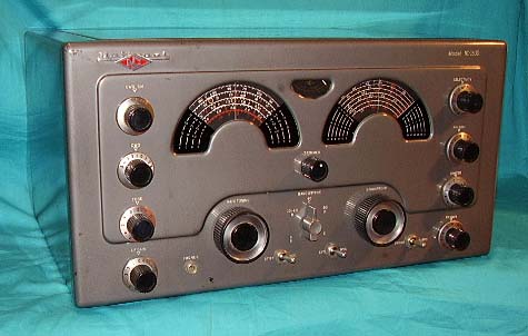
Not my current
NC-183D,...
I had this one in 2003. I bought it with the
matching NC-183DTS loudspeaker at Reno Antiques for $100, a bargain
even then. Unfortunately, I sold it a few weeks later out of the Western Historic
Radio Museum to a visiting ham looking for a vintage receiver. |
But,...back to the NC-183D problem,...the "microphonics" turned out to actually be "motorboating"
that was caused by a leaky 6BA6 tube used as the 2nd IF
amplifier. I had been all through this receiver just a couple of
years before and had replaced all of the paper dielectric
capacitors, so I was pretty sure the problem would have to be
"tube related." I replaced the bad tube and the receiver was
"back to normal."
Now, I'm using this NC-183D to drive a 1950s vintage 15"
Jensen coaxial speaker housed in a 1940s vintage Jensen
KM bass reflex cabinet. Wow! Great sound,...even some of
the SSB signals seem to have extended bass in their
audio. The NC-183D is one of the few post-WWII ham
receivers that can provide enough audio power to drive
the Jensen KM bass reflex box effectively. Though P-P
audio was common on many "high-end" ham receivers
pre-WWII, after the war, most ham gear came with
"military-grade" audio that was promoted as
"communication audio." The favored audio response for
"communication audio" is 300hz to 3000hz - great for
listening to a
carbon mike used on the battlefield - not so great for
anything else. |
|
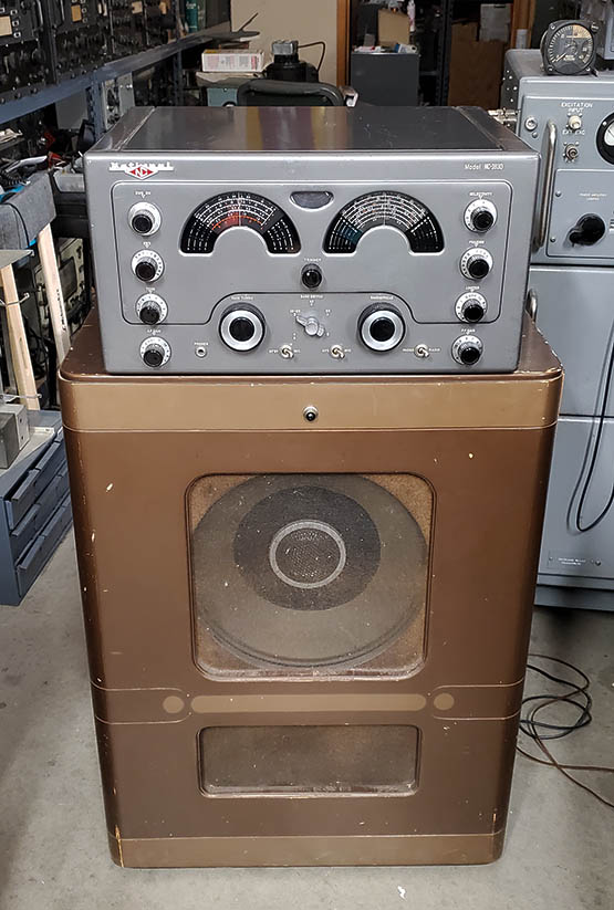
My current NC-183D
SN: 430 0135
was located in the shop
It's setting on top of the
1940s Jensen KM Bass
Reflex Box with a 1950s Jensen 15" coaxial speaker inside. The
NC-183D is one of the few communication-type receivers
that can really drive this speaker box and produce a lot
of bass response. 8 watts of V-T audio
is available and up to 11 watts peak audio. The shop
antenna used is a 130' CF Inv-Vee fed with open feed
line to a Nye-Viking MB-VA coupler. Note the T-368
transmitter behind the NC-183D and KM box.
I now have an
original NC-183DTS loudspeaker, that's the 10" speaker
in a matching table cabinet, so I probably won't be
using this Jensen KM set up in the future.
Or, so I
thought,...I moved the NC-183D back out to the shop in
June 2024 where it's again connected to the Jensen KM
box and used as the station receiver with the W6MIT 300W
transmitter. |
| As for AM-BC
reception,...absolutely nothing of listening interest over the air around here. Shortwave BC has a few interesting stations and in the mornings mainland China SW-BC stations
"pound in" here. The Chinese stations have excellent audio with lots and lots of
modulation and very wide audio bandwidth. I have no idea what
they're talking about but they sound great and it's
likely they are actually being "relayed" from Cuba,
which is why they are very strong. Sometimes
there's interesting
idiomatic music,...for a large variety of Chinese percussion
instruments
accompanied by mirliton soloists (a mirliton, also known as a
reed-flute, is a membranophone with finger-holes like
a recorder-type flute but it sounds like a kazoo) try
Firedrake, the PRC
jamming station located on Hanon Island. If you can manage to listen to
Firedrake long enough, you'll notice
that the music is on an approximately one-hour long "loop" that just
keeps repeating the same program material, over and over and
over,...well, it is a
jamming station,...you're not really supposed to enjoy listening
to it. |
|
SN
430 0135 Revisits the Workbench in 2024 |
| Back on
the Bench - Mar 5, 2024 - Mental Recall Deficiency
- It's funny how you think you remember exactly what you
did and precisely how you
did it only to find out later that you really didn't remember
anything at all about the project! Well,...that's
what I realized when I pulled the
bottom cover off of the NC-183D. Right there in front
of me,...the entire chassis was recapped with CDE 715P
Orange Drops. Not only that, but I had replaced ALL of
the electrolytic capacitors, including the multi-section
filter cap. I don't know where I came up with that
"Yellow Jackets" and "paper dielectrics only" thought. Installation of all of the new
(okay, six year old) parts was just as it
should be. Oh well,...maybe I need more vitamin D or
something. Lots of work saved on this one.
Here's what I think still needs to be accomplished,...
1. Clean the top of the chassis. I can tell I didn't do
that. It's not real dirty but it could use a little
detailing. Cleaned with WD-40 and Glass Plus because
it really was pretty dirty
2. Replace all ten of the tube shields. They're
oxidized and darkened. I should have some good condition
shields of this type,...I ended up wire brush
cleaning the originals but the "parts set" may provide
better ones
3. Clean dials, dial covers and meter glass. The meter glass looks like it
has something on the inside of its glass. Cleaned with Glass Plus, the
S-meter had to be disassembled to clean the smoky dirt on the inside
the meter
4. Test all of the tubes. I did this in 2018, so it
should be done again. Replaced three tubes,...two
tested at minimum and the other one, one of the 6V6GT
tubes, had a severely
cracked bakelite base
5. Clean the tube sockets. I don't think I did this six
years ago, but who knows? Used DeOxit applied with a
small paint brush
6. BFO frequency control shaft seems very loose. It does
work but the control shaft is loose feeling. I used two
knob felts to lessen movement. Big problem inside BFO
can,...broken ceramic base on air variable C.
7. Clean cabinet. Other than a "wipe-down" I know I didn't do this. I can also
detail the paint since there are several tiny scratches. The scratches didn't
clean off with Glass Plus,...already lots of old
"touch-ups"
8. Dial covers Band Indicators,...I don't know if I'm
going to try to recondition these or not. The white fill
paint is present but it's very thin and showing quite a
lot of wear. Nothing works for this problem except
replacement
9. Check alignment, it should be okay but we'll see.
RF Tracking alignment needed
10. I'll shoot all new photos but I'll save the one of the NC-183D on the
Jensen KM box and the 2003 NC-183D.
|
|
Tubes -
It's been six years since I tested these tubes and for
three of those years I didn't have the receiver so I
don't know how many times it was used or for how long it was operated during that time. Most of the tubes
tested much higher than minimum acceptable, almost like
new tubes. But, one 6BE6 was right at minimum so it was
replaced. One 6BA6 was slightly below minimum so it was
replaced. One of the 6V6 tubes had a cracked bakelite
base that was allowing the tube envelope to loosely move
around. This
tube tested good but I'm going to replace it anyway. So,
three tubes replaced out of the 17 in the receiver. As
the tubes were reinstalled, I used a small paint brush
to apply a small amount of DeOxit to the tube pins to
help clean the socket pins.
Chassis Test
- With all of the tubes reinstalled along with their
shields I applied power to the chassis. I had the
NC-183DTS connected and a ten foot test antenna. The
receiver functioned with the matching NC-183DTS speaker
but I was noticing a very slight "roughness" in the audio
quality and,
with the BFO on, CW was slightly garbled (but definitely
noticeable.) |
Mar 6, 2024 -
Monumental Error Produces Garbled Sound on CW - The
heterodyne tone sounds garbled (heterodyne tone
modulated by a low frequency from somewhere.) AM reception seemed okay
but, listening critically, AM did sound slightly rough
and SSB voice was slightly garbled in the lower audio
frequencies. This
required a RF Signal Generator to determine the
distortion's origin. Oddly, the signal injections showed that
the problem seemed to be power supply related. What
was causing the garbled sound is a
total
embarrassment to admit to. When I installed this
National power transformer six years ago I missed
soldering the wire at terminal 3. The wire was tinned
and wrapped correctly on the terminal but not soldered.
This is the filament "hot" voltage to the entire
receiver. Of course, the wrap was obviously making some
sort of connection but I could actually wiggle the wire on the terminal and that
couldn't have been a "solid connection." I soldered this
wire to the terminal and the garbled sound disappeared. I wonder what else I'm going to find as I
further check out the receiver performance? |
Chassis Cleaning
- I thought this NC-183D was pretty clean but it really
wasn't. I used WD-40 to loosen the grime and then Glass
Plus to remove the WD-40 residue. The tuning and band
spread capacitor area was very dirty and there was an
oxidized deposit on both sides of all of the metal
dividers between each section. I had to use WD-40 to
remove it,...it did just wipe off so
not too bad, just odd. I had to use acid brushes, long
handle paint brushes, Q-tips and
paper towels for cleaning implements. Afterwards, I
applied a small amount of DeOxit to the rotor contact
springs on both variable capacitors.
Tube Shields
- These are the push down type that
are held in place with four vertical flat spring fingers. I checked my junk tube shield boxes and none of these
type of tube shields are really in very good condition.
Since these are all of the original tube shields, I decided to wire brush the originals
using a steel bristle tooth brush. They don't
look too bad after that treatment,...and they are the
originals. NOTE: I checked the bag of loose parts with
the parts set NC-183D specifically for the tube shields.
They are in better condition so I may harvest those.
Trouble is I could only find nine shields in the bag and
there were ten originally,...and they aren't the same
brand as the original set of tube shields,...bummer.
It's better to keep the all-matching originals. |
Mar 6, 2024 -
Cabinet - I noticed when I removed the
chassis from the cabinet that someone in the past had
"touched up" the paint in lots of places on the exterior
of the cabinet. These were all minor touch-ups, nothing
really large, just lots and lots of small nicks and some
scratching from someone using a screwdriver to pry off
some of the knobs (unbelievable!) Also, some circular scratching from knob
skirts that were too close to the panel and a little
"fat-finger syndrome" around the band switch knob. The
touch up paint used was a very good match because I
really never noticed that there was quite so much
"touching up" done,... until I looked closely at the
cabinet. But, it's a good "touch-up" job. I didn't really fully clean this cabinet
six years ago and it looks like it has picked up more
dirt since then, probably from being in the shop for the
past year or so. I dismounted the dial covers because
the band indicators are easily damaged by just about
anything coming in contact with the thin fill paint that
National used. Luckily, there aren't any dents or bends
in this cabinet, it's nice and straight. Thorough
cleaning with Glass Plus. Hardly any color on the paper
towels indicated that the cabinet was actually very
clean. S-meter -
I had to take the meter out of the case to clean the
inside of the glass and to dust the meter scale. The
improvement was very noticeable. I don't know how the
"smoky film" got inside the meter but it was
really obscuring the meter scale,...weird.
|
|
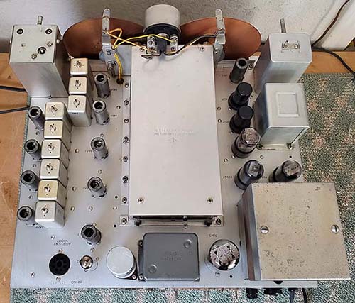
NC-183D Top of Chassis
SN: 430 0135
This chassis is very clean.
Unfortunately, the power transformer, although it is a
National type from an early NC-183D, isn't original to
this late NC-183D chassis. See photo below for what the
original S461 potted power transformer looked like.
There may have been a second type of potted power
transformer used in NC-183D late production that closely resembled the S669 Filter
Choke. It was painted the same dark gray color as the
choke and was also identified as S461. |
Power-up and Testing
- I listened on 20M for quite a while using the
Collinear Array antenna. Heard a couple of
EA-Spain stations working US hams. No distortion in the SSB signals. Tried CW and good clear heterodyne now.
Listened to a couple of SW-BC stations and only the
relayed Chinese PRC stations seem to have good audio. They are
strong here in the morning. I listened later in the late
afternoon and copied XSQ on 16.989mc, Chinese Marine
Beacon. Later, in the early evening, I copied SVO on
8.424mc, a Greek Marine Coastal station, Olympia Radio,
located in Pirgos, Greece. Also,
copied TAH on 8.431mc, a Turkish Coastal station in
Istanbul. All of the coastal stations use CW Morse for
their identification.
Reassembly - The chassis has to be installed
into the cabinet to check RF tracking accuracy. Before I
do that, I have to double-check that the dials are
mechanically synchronized with the tuning and band
spread condensers. Then, when the chassis is in the
cabinet, the dial covers can be "zero'd" and then the
accuracy of the RF tracking checked. The chassis was
installed into the cabinet. The dial covers had been
installed first and then the chassis can go in. Once the
chassis is installed, then the dial covers can be
mechanically set for zero and then the RF tracking
accuracy can be checked. The accuracy was checked on
20mc, 15mc, 10mc and 5mc WWV. None of the dial indications
were "right on" with half of one division
being the typical error. So it looks like I'll be doing a RF
tracking alignment. RF
Tracking Alignment - This was just a very
minor tweaking of the adjustments. The tracking was
pretty close but the NC-183D can be aligned for a "right
on" readout on the dial. That's what the minor
adjustments accomplished for all bands. |
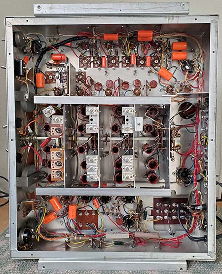
NC-183D Under the Chassis
It was a surprise to find that I had
already installed these Orange
Drops six years earlier. |
| NC-183D SN: 430 0135
- Performance
- I have the NC-183D connected to the NC-183DTS
loudspeaker and to the Collinear Array antenna.
E - Dial
accuracy okay. Not much on AM-BC to allow judging the
audio quality. Super-accurate tracking on Band E
requires moving a coil that wraps two turns around the
outside of the LO coil. This coil is difficult to move
very much due to the heavy gauge wire used. The
placement of this coil controls the middle part of the
band tracking. The band ends usually are tracking but
the center of the band is off slightly.
80/D - Strong
signals on 80M band. Using the logging scales for
frequency reset will require some future set-up.
40/C - Strong
signals for both ham and SW-BC, 5mc WWV and 10mc WWV are
"right on frequency" SW-BC in the 31M band sounds great,
TAH and SVO copied in the 8.4mc region.
20-10/B -
Strong signals from ham, SW-BC and utility stations. 20M
loaded with signals, 15M busy during contest weekend,
10M busy during contest weekend. 15mc WWV and 20mc WWV
are "right on frequency." Copied XSQ 16.998mc and XSG
16.954mc and Trenton Military 15.035mc USB.
6/A - Signal
generator is no problem to receive but real signals are sparse and
what is heard is unidentifiable. An actual 6M antenna
could help but I don't think there's much activity
around here. Propagation undependable.
The NC-183D is very sensitive and I really think
anything that's "on the air" can easily be received provided
propagation conditions allow for it.
Selectivity is much "tighter" than the NC-183 and is
especially noticeable when tuning on Band B. The Crystal Filter
would only be needed if the QRM was very close to the
operating frequency. Tone control works quite well at
reducing highs. BFO injection is sufficient for SSB and
CW
signals but proper demodulation will require some reduction of the RF gain.
The AVC can be left on when tuning CW or SSB. |
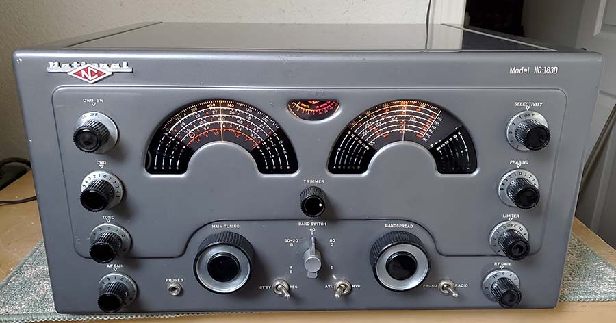
NC-183D SN: 430 0135
The NC-183D after
its bench revisit was completed. I took this shot to
show the illuminated Lucite dials and the illumination
of the S-meter after its internal cleaning. The worn
band indicators are a detraction that's impossible to
fix. BUT, take a look at the last photo in the next
section. It's the same
receiver but with excellent condition replacement dial covers
(provided from a "parts set") installed. |
|
Are We Ever
Really Finished With a Restoration? |
|
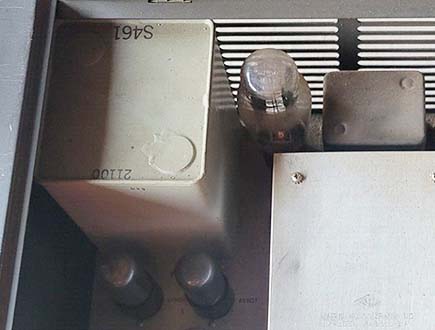
Later NC-183D Potted Power
Transformer S461 still in the second "parts set" SN: 396 0086 |
More Rework in the
Future? - Here's what I'd do
IF I had another
(a
second) "parts set" that had
the specific parts I needed and they were in good usable condition.
1. Dial Band Indicators
- The only fix for the worn band indicators problem is replacement with good
condition
original dial covers.
2. Power Transformer
- The S461 potted transformer is the original type that
was missing when I got the receiver. See photo to the
left showing how some types of S461 transformers looked.
There were other suppliers of NC-183D potted
transformers that are slightly different shapes and
different colors but they too are identified as S461.
3. BFO Assembly
- I used the BFO off my NC-183D "parts set #1" for the NC-173
restoration
and it was identical to the earlier style BFO. I need
a late-style BFO for examination of the mechanical "tightness"
of the air variable shaft and to see if the internal
assembly is identical to the early version. If it's
identical,
then there's something wrong with the BFO tuning air
variable in the original BFO of SN: 430 0135. I don't
want to pull the original BFO assembly unless I have a
replacement, if necessary.
4. Dials - The
dials on my "parts set #1" are actually of a
better build-quality than these later original dials
that have several internal (from the factory) blemishes.
The blemishes are little bits of white that apparently
weren't cleaned off before the Lucite dial was mounted
(rivets) to the
backing plate.
5. Cabinet - I
thought the "parts set #1" cabinet was in better
condition than this original cabinet that has had lots
of touch-ups, including trying to cover scratches from
prying off knobs and "fat finger syndrome" around the
band switch. A closer examination revealed that the "parts set
#1" cabinet has one blemish that's rather severe, a
super-deep scratch (well into the metal) by the band
switch nomenclature. If
another NC-183D "parts set" (#2) turns up with the
needed parts, 430 0135 will go back on the bench. "Parts
sets" seem to always be a necessity when doing full
restorations. It's unfortunate that high shipping costs
have usually made the total cost involved when buying a
"parts set" prohibitive. |
| Number 2 - Another
"Parts Set" Found - Mar 22, 2024 - It
took a little searching to find a NC-183D that had the
parts I needed and was in really deplorable condition
so the price would be somewhat reasonable. The shipping
costs are astronomical for a 65 pound radio no matter
where it's coming from and since there's nothing that
can be done about that I just concentrated on finding a
"parts set" that matched my needs. The NC-183D found is
very close to being from the same time period. Its
serial number is 396 0086, so production run 396 and my
"D" is from production run 430 indicating that
the two receivers are probably only one production run
apart. The "parts set" power transformer is the large
potted S461 in a light gray color. Next, were the dial
covers. While these two pieces of Lucite are pretty
dirty, the white nomenclature for the band indicators is
all there with no missing paint. They will have to be
very carefully cleaned to preserve the white fill paint.
Then there's this "parts set's" BFO. The frequency control is tight, just like would
be expected. This indicates that something IS
wrong with the BFO on 430 0135 and, now that I have a
replacement, I can dismount it and see why the frequency
control is so loose feeling ("gotta know" curiosity,...I'll
be replacing that BFO assembly with this one from this
second
"parts set.")
SN: 396 0086 became a
"parts set" (I think) because of the filter
choke (pn S669) overheating. There's black wax that
has oozed out around the bottom seam indicating it got very hot
but (amazingly) the choke still tests okay (for DCR
only.) More than likely, several "leaky" bypass
capacitors probably increased the load on the B+ causing
a slow but constant heating in the choke when the receiver was
operated for long hours (a shorted filter capacitor would
probably have blown the fuse but might also have caused the choke winding to go open
quickly without
the long-term heating.) Sometime after that problem,
the Crystal Filter assembly was completely removed. Both
tuning knobs are gone and the Band Switch knob has a
pointer knob (so-called "chicken head" type.) All of the
vacuum tubes were still installed along with all of the
tube shields. The cabinet looks like a typical "parts
set" with severe scratching on the panel area. The
receiver obviously was kept as a valuable "parts
source." Much later, these types of radios are found by
"estate pickers" and then show up on eBay. The "trick"
is to find a seller on eBay that realizes the receiver that he's
selling IS NOT restorable and IS A PARTS SET
that's priced accordingly. Considering Parts Set #2
was able to supply a good working S461 power
transformer, an excellent pair of dial covers, an
excellent MT dial and BS dial, a good working BFO
assembly and a good VR load resistor 3900Ω 10W (original
sustained a
broken wire lead at the component body,...happened while installing the power transformer) the
price of $125 for the receiver seems reasonable.
Unfortunately, the shipping of a 70 pound package from
Ohio to Nevada ended up being more than the cost of the
junk receiver. But, if the parts I used had been purchased and
shipped separately, the total cost would have probably been even
more,...and, without a doubt, the time involved would have seemed endless. |
| Scavenge the Parts
- I performed a preliminary test on the power
transformer that really was nothing more that measuring
the DCR of the windings. This will just show if there any really
terrible problems, like open windings. The full test
will be with 120vac applied to the primary and measuring
the secondary voltages and, if they measure correctly,
letting the transformer run with no load for about 30
minutes. If the transformer remains cool, it's probably
okay to use.
Further power transformer testing was performed with 120vac
applied to the primary winding. 680vac was on pins 4 and
6 of the rectifier tube socket (all tubes were removed) and
5.8vac on pins 1 and 8. The 6.3vac winding still had the
dial lamps installed and the winding measured 6.7vac. I
let the transformer remain powered up for 30 minutes and
it remained cold to the touch. It should be good to use.
Extracting the BFO assembly requires
unsoldering three wires and removing two 6-32 nuts and
washers to dismount. Inspection should reveal if there
are any
mechanical problems.
Transformer Transplant
- This transplant operation was somewhat lengthy in that
the S641 had to be removed from the parts set. Then the
transformer in 430 0135 had to removed. Then S641 was
installed into 430 0135. Straight forward rework with no
problems (except I broke R42 while swapping power
transformers.)
BFO Transplant
- I wanted to see why the BFO frequency control shaft
was so loose on 430 0135. It became apparent after dismounting the BFO
and looking inside. The ceramic base for the air
variable capacitor was broken (cracked through the bearing
hole) and that prevented the spring
from providing the proper pressure on the rotor shaft thrust bearing. This is the second BFO of this type that
I've come across with a broken ceramic mount.
Apparently, if the BFO frequency knob is hit hard directly from
the front and the knob has some panel clearance, that
"hit" can push the BFO shaft back with enough
force to break the ceramic mount inside the BFO can. Indication of this
problem is a very loose feeling to the BFO frequency
shaft and any lateral movement of the BFO shaft. I
inspected the BFO that I had taken off of this parts set
and it
was in good condition. It had the same part number
stamped on it as
all of the NC-173, NC-183 and NC-183D receiver BFOs,...so they
are all interchangeable. The installation of the parts
set BFO was straight forward with no problems.
|
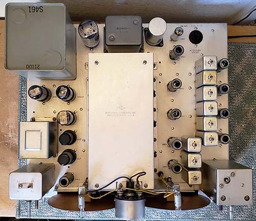
Original type S461 Potted
Power Transformer and new BFO installed |
|
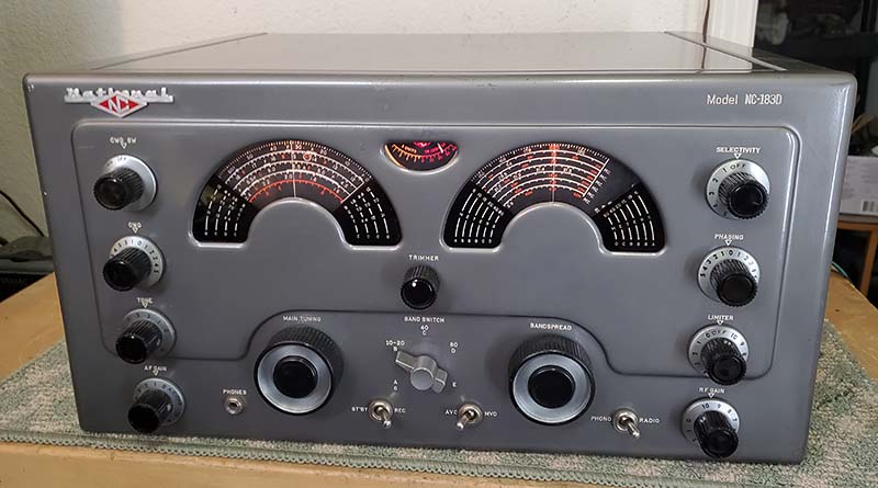
NC-183D SN: 430
0135
The good condition replacement dial
covers are installed and they really make a difference.
Compare to the last photo in the "Revisit the Workbench"
section above. Those were the old dial covers,...it's
easy to see the difference. The original type S461
potted power transformer is much larger than the older
style power transformer. S461 remains cool during long
operations. In the photo, the receiver is tuned to 15mc WWV with
S-meter showing S9+30db, antenna is the Collinear Array. |
Cleaning the Dial Covers
- Dismounting the Dial Covers required removing the chassis
from the cabinet (I had done that earlier to remove
parts from the chassis.) The dial covers mount on
the inside of the cabinet with two screws on each dial
cover. The Lucite dial covers were very dirty. I
carefully used just a slightly damp paper towel (using
Glass Plus) to remove the dirt around the white band
indicators. I had to also use a slightly damp small soft
paint brush to carefully remove the dirt that had
accumulated on the white fill paint. Q-tips were also
used to clean between the nomenclature. All cleaning has
to be done with just slightly damp implements to avoid
removing any of the white fill paint. I didn't want to
clean the white fill paint aggressively for fear of
damaging it. As it was, I was able to gently clean the dial covers
and the white fill looks in very good condition.
Finalizing Things - Mar
24, 2024 - I double-checked the power
transformer wiring. The bottom terminal plate is exactly like
one on the old style
power transformer so the installation was easy. With the
NC-183D still out of the cabinet, I applied AC voltage
using a Variac,...just in case. No problems and the
receiver came up as expected. I installed the
replacement dial covers into the cabinet and centered
them before snugging-up the mounting screws. One has to
be careful not to rub the dials or dial covers with
a dry cloth as this will statically charge up the Lucite
and that attracts dust rapidly. Discharge by using a
damp paper towel on the back of the dial covers. The
dials don't charge up as much since they are riveted to
the copper backing plate. I just used a soft paint brush
to remove the dust before installing the chassis into
the cabinet. When installing the rear panel and lid,
first install but don't tighten the chassis bottom
felt-cup feet. Next, install all of the rear panel
screws loosely. Make sure the lid is setting squarely in
the lid-well. Then tighten the rear panel screws "one at
a time" watching that the lid remains squarely in the
lid-well. Once the rear panel screws are snugged-up then tighten the bottom
felt-cup feet. This method will keep everything square
and the lid will set flat and be easy to lift up. The knobs
were then installed. I had marked the BFO shaft so I
would know how to set the knob. When tightening the
dress nuts on the switches and phone jack, only tighten
these "finger-tight" - just enough so they don't move
when operated. Install the bottom cover to complete.
Operation
- The receiver is still on the work bench, so it's
connected to the Collinear Array via a 50' length of
RG-58U coax. The operations seems to be just as it was
before the two transplants. Dial accuracy after
reassembly is still accurate. |
| NC-183D
Madness
- What? MORE work? I don't know what to say,...but there
are two things that really should be taken care of.
First,...I didn't
inspect the new BFO assembly other than just looking at
the ceramic air variable-C base. I didn't DeOxit the
vari-C or the
on-off switch.
Now, I'm noticing that the BFO frequency adjustment is a little erratic. Unfortunately, the BFO
can has to be taken off of the chassis to do this little
task that should have been done the first time.
Second,...the more I look at these original dials the
more small imperfections I see. Things like crooked
numbers, little bits of white debris, little missing
sections of numbers. It looks like the silk-screening
had somehow gotten really wet at sometime in the past
and that's why the silk-screening has flecks of white and partially missing numbers. Also, the BS dial is bent in relation
to the hub. I
inspected and cleaned the dials on Parts Set #2 and
these dials are really in nearly perfect shape. I also
have the dials from Parts Set #1 and these are also in
very nice condition. Replacing the dials is a
"chassis-out-of-the-cabinet" job so I'm going to give it
a few more days of thought while running the receiver
everyday. This is sort of a "shake down" to see if
anything else turns up. I dismounted both dials from
Parts Set #2 and thoroughly cleaned them. They are very
nearly perfect and straight.
NC-183D Dial Removal
Procedure - To remove the dials, first
loosen the dial hub set screws. Then loosen
the two set screws on the dial drive gear. Using a small
rod (<0.250" diameter) push back the dial
shaft through the dial hub but not all the way through
the drive gear hub. Then you can lift the dial straight up and
out. It automatically disengages the pinch wheel and
there's no bending or stressing any of the
parts. When reinstalling a dial, insert the dial into
position and engaged with the pinch wheel. Then push the
dial shaft all the way forward through the drive gear and through the dial
hub. Adjust the position of the drive gear, the dial
(dial stops in relation to the lower end of scales on the dial
and full mesh of the tuning condensers) and then tighten
the set screws. Test for proper operation.
NOTE: Be
careful when pushing the dial shaft through the dial hub that the drive gear says engaged with the
split-gear on the tuning condenser shaft and do not push the dial shaft all the way through
the drive gear hub. If you do, you'll have to reset the
anti-backlash on the split-gears on the tuning condenser
drive gear. You only need to push the dial shaft back
just enough to clear the MT or BS dial hub. Mar 28, 2024
- I performed the usual ritual to get the chassis out of
the cabinet. This was followed by taking the BFO
assembly off of the chassis. Looking inside I could see
that it was easy to apply DeOxit to the rotor contact on
the air variable. The on-off switch could be seen by
looking along one corner at the top of the can. Using the red spray
tube, DeOxit was also applied to the on-off switch. I
then reinstalled the BFO assembly.
While I had the
DeOxit out, I also cleaned the band switch with DeOxit
and a small paint brush and I also cleaned the
double-conversion switch contacts (another task I
neglected to do the first time 'round.)
The MT and BS dials were replaced following the
procedure above. These new dials were from
Parts Set #2. I mechanically aligned the two dials as
indicated.
With the receiver chassis still out of the cabinet, I
connected the speaker and a test antenna to verify that the BFO action was improved and it was. Very stable
now. It
drifts as the receiver warms up but just a steady
drift,...nothing erratic. The cleaning of the BFO rotor
contacts might have caused the improvement or it could
be that this time I routed the BFO wires like the
original BFO assembly had been routed and also moved a capacitor that was
laying against the wires.
But, this was "out of the cabinet."
Out of the three NC-183D cabinets I now have, the
original one is actually in the best condition, so it
will continue on as the "proper" cabinet for 430 0135.
Mar 29, 2024
- The chassis was installed into the cabinet as
described before. A slight adjustment on the BS zero
using the dial cover adjustment was required. There was
no significant change in performance other than
stability in the BFO seemed to be improved (at first.) Both dials are now
excellent. Of course, the blemishes on the original
dials were so small they wouldn't even show in a photo.
But, when using the receiver, one's eyes are only about 18" away from
the dials, so these tiny but numerous blemishes are very apparent. These
dials from Parts Set #2 are extremely nice, nearly
perfect.
Weirdness
in the Workshop - Apr 3, 2024
- The BFO is erratic acting with the receiver in the
cabinet. I remembered that I was having this exact
same problem with the NC-183 a couple of months earlier
and that instability problem went away when I moved the
receiver to the ham shack. So, I moved the NC-183D to
the ham shack. The receiver powered up with the normal,
expected drift but nothing erratic. I left the NC-183D
running for about an hour. I went to 20M CW and the
signals were perfectly stable. This is weird because it
suggests that the problem is in the upstairs workshop.
This might be one of two things. The antenna coax comes
from the ham shack to the workshop using a 50ft length
of RG-58U. BUT, I've also tried the Pixel Loop (also
located in the ham shack) connected with about 100' of
RG-6U and the instability was still present with either
antenna so that should eliminate that as a source.
Anyway, antenna problems shouldn't change the receiver
LO frequency or BFO. The
only other thing I can think of would be random fluctuations in the AC line voltage or
(more likely) at the AC outlet that I use in the workshop. Watching
the AC line with a 'scope might show something but if
there's a problem it might be due to current draw so I'd
have to power up something. At any rate, the problem
apparently isn't with the NC-183D but is in the upstairs
workshop itself. Apr
7, 2024 - "On the Air" Assessment -
I operated the NC-183D with the Viking 1 transmitter using
the Collinear Array antenna. This was on the Nevada Mil-Rad
Net. Reception was excellent and the audio reproduction spectacular,
even though I was just using the NC-183DTS 10"
loudspeaker. Never a problem with copy even though a
couple of times some signals approached the noise floor.
On the audio, I thought I'd be able to tune to one
sideband or the other to capture more audio highs but
apparently the actual shape of the IF bandwidth and its
narrow nose attenuates the signal rapidly as it's tuned
off of center. Signals sound best when the carrier is tuned "on the nose." The
Tone control can increase the highs if more are desired
but I kept the Tone control on 3. The Noise Limiter was
a surprise because normally they are ineffective on
modern types of RF generated noise but the 183D NL worked
on our modulated blower-speed furnace RFI noise. At the
end of the net, one signal went close to the noise floor
and the furnace was running creating a S-7 noise level.
I was surprised that the NL allowed reducing the blower
RFI noise to almost nothing and allowed good copy of the weak signal.
Naturally, most of the AM signals are much stronger than
the furnace blower RFI (average net AM signals run ~
S-9+20db) so they effectively over-ride the furnace QRN.
Since the mode of operation was AM, drift was not even
noticed. About 45 minutes into the net, I turned on the BFO to see how stable it would be and its heterodyne
never varied in the time I had it turned on. I did use
this very same NC-183D "on the air" one time
before this and that was about six years ago after I had rebuilt it the first
time and it was a good performer then allowing solid copy on
weak signals. But, as mentioned before, I sold it but
after three years was able to "trade it back" although
it languished out in the shop after getting it back,...for a couple of years! Now, six years
after that first use of this NC-183D, and after another rebuild, another
alignment, then several partial parts swap outs
involving two other NC-183D "parts sets" and then even
more bench time,...I think I'm done with this NC-183D.
These receivers are an excellent choice for the vintage
AM ham station where the operator wants to enjoy just
about the best audio reproduction along with
great selectivity, a fine Noise Limiter, competitive
sensitivity and an impressive bench presence.
June 14, 2024 - Out to
the Shop - I really wasn't using the
NC-183D upstairs so I've decided to move it back out to
the shop where it can be reconnected with the Jensen KM
bass reflex box with the Jensen 15" coaxial loudspeaker.
Before, when I was running the NC-183D with the Jensen
KM, the receiver had several problems that have now been
corrected with the multiple trips to the workbench. I
moved the KM box to be a little further back in the
shop, about ten feet from the operating position. I used
30' of 18ga. "zip cord" that I routed up to the ceiling
and across using cable hangers. Then the speaker cable
drops down
to the KM box's new location. I did the same thing with
the antenna coax coming from the "Big Rig," that is, I
routed the RG-58U out the top of the transmitter up to
the ceiling and used two of the cable hangers that held
the transmitter RG-8U and then dropped the RG-58U
receiver coax down to where the receiver is located. I
tested the "sound" by listening to a couple of local
AM-BC stations (the only thing they're good for is
testing) and with the KM's new location further away the
bass becomes very noticeable, which is good. When the KM
box was very close and directly in front of me, all I
could hear were the highs from the tweeter (it's a
coaxial speaker) but now the audio spectrum seems to be
reproduced with a mellower, slightly bassy sound, which
I find pleasing.
I'll alternately operate the NC-183D and the RACAL
RA6117A with the W6MIT 300 watt homebrew transmitter.
The shop antenna is a 130' Inv-Vee fed with 44' of open
feed line to a Nye-Viking MB-VA antenna tuner. |
|
Restoring the 1948 NC-183 SN: 241 0262
This NC-183 had
excellent cosmetics on the outside but unknown hidden
terrors were lurking inside. Was it commercially-owned
receiver or
just a amateur station receiver belonging to an enthusiastic ham?
It seemed
that nearly constant operation had resulted in hours upon hours
of wear and tear on almost everything that moved inside
the receiver.
Countless, senseless repairs had been accomplished using
randomly-found parts installed with the most indifferent
workmanship, definitely pointing to amateur-level maintenance.
It soon became evident that the receiver had been in daily operation by a
"five packs-a-day" chain-smoking ham that must have
blown his
cigarette smoke into the receiver hour after hour, day
after day, year after year. The cigarette smoke combined
with the humid environment from where the receiver was
used left a nearly impenetrable coating on the chassis. After a close
inspection, I'm sure the "as-found" condition showed
that SN:241 0262 was an over-used ham receiver that was operated long hours by
a heavy
smoker and the receiver's amateur-level maintenance was performed in a
technically incompetent manner. The interesting
thing is that the exterior of the receiver was in
excellent condition and that can be deceptive when
relying just on photographs for pre-purchase initial overall condition
inspection. Well, this receiver's
restoration should provide some interesting commentary
and observations. |
|
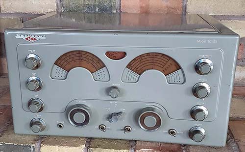
NC-183 Receiver SN:
241 0262 ca: 1949
This NC-183 is on production run 241
which is before any of the HRO-50 production runs that
start at run 280. The last HRO-7 receivers were produced
on run 232 and that indicates that this NC-183 was produced shortly
after the last of the HRO-7 receivers, probably sometime in
1949.
The earliest run number seen on a NC-183 was 202, maybe
produced in very late-1947. The dials on the receiver shown have
the typical darkening of the phenolic-acetate dials. This photo was taken before any
cleaning or restoration was performed and shows the great
exterior condition. Too bad the same can't be
said for the interior. |
NC-183 Initial Inspection - Jan 11, 2024
- The receiver cabinet was taken apart by
removing the bottom cover then removing the rear
panel and lid assembly. The knobs had to be
dismounted, then the dress nuts on the switches
and the phone jack. Before removing the chassis
from the cabinet the two dial guides above each
of the dials have to be removed. The four
felt-cupped feet had to be dismounted and then
the cabinet can
slide forward to have the chassis fully exposed.
I pulled all of the tubes and placed them in a
box with the knobs and hardware.
The next step
was to test the "iron." The power transformer
supposedly was tested by the seller and it did
test good. The filter choke however was open.
This choke is exactly the same part number as
the filter choke used in the HRO-60 receivers,
SA-6294, of which I had a spare. Also, the parts
set NC-183D had the same part number choke still
in place. So, that was lucky. The audio output
transformer tested good. All of the IF
transformers tested good.
The visual inspection revealed that a few
capacitors had been replaced over the years (two with molded
plastic paper-dielectric types and one with an orange
drop.) Also, two ceramic disks were added to the
1st RF amplifier and the Mixer tubes that
connect the suppressor grid to chassis but the
suppressor grid was already wired directly to
chassis so I don't know what the intention of
these capacitors were (but replacements will not
be installed.) Also, three of the four square brown plastic molded
capacitors were split-open (see photo below.) It doesn't look like these capacitors
"blew" or "swelled." It looks like the plastic
housing just split apart for some reason.
Tuning condenser front mount nuts were very
loose. Had to tighten from underneath after
removing the two dial pinch-wheel drive
mechanisms (these nuts actually had to be
adjusted when setting up the pinch-wheel drive
for each dial.)
Other Mechanical Problems
- The tuning dial was completely immoveable but
the band spread dial worked fine. Both of the
pinch-wheel drives were not engaged to the
rim of either dial. The Noise Limiter control is
frozen in place. The loudspeaker output
connector is a special three pin mini-socket type.
Probably from the
indifferent packing, the rear panel is bent in two places. This
is causing the lid to not set square in the recessed lid well of
the cabinet. Also the front lower lip of the cabinet has a
slight bend. Closer examination actually revealed many more
bends to the metal, especially in the lower front panel area. |
|
Main Dial Drive -
The drive gear shaft was frozen in the bearing. I found that
dirt and grease had hardened and heat broke it loose. I still
had to disassemble the entire drive because of rough, grating
feel to the tuning. I pushed the shaft out of the bearing and
found the set screws had galled the shaft. I filed the galled
area to allow easy reassembly. I had to clean and lube the
washer-spacers and the shaft. When reassembled everything worked
smoothly. The dial rim was not engaged into the pinch-wheel so
by loosening the pinch-wheel mounting I could get the dial rim
into the pinch-wheel. Although both of these dial drive mechanisms
for both dials need to be thoroughly cleaned, it is working smoothly now
with some slipping due to the dirt-contamination. Later, I took
a closer look at the Band Spread dial mechanism. I could see
that the drive gear had quite a lot of wear that was probably
due to excessive anti-backlash pressure and a lot of tuning. I had to disassemble
the Band Spread drive to clean and relube. After that the tuning was still
rough-feeling caused by the excessive wear to the drive gear
teeth. I harvested an excellent condition drive gear
from the NC-183D "parts set" (the gears are the same part number
and exactly alike) and installed it into the Band Spread tuning.
I adjusted the anti-backlash split-gear for just enough pre-set
for proper operation and then "snugged up" everything. Now the Band Spread and the Main Tuning drives are
both very light feeling and the pinch-wheels shouldn't have any
problem driving the Tuning and Band Spread condensers.
Removed and Cleaned Dials
- I used Glass Plus to remove the nicotine staining then
polished with a soft flannel cloth. Wrapped with paper towels
for protection until I'm ready to reinstall. Finished dials are
shown to the right. The remaining discoloration is inside the
plastic and can't be removed.
S-Meter -
Dismounted the S-meter for later cleaning. Stored in the parts
box. |
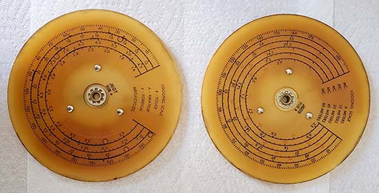
NC-183 Dials after
damp-cleaning. This is about as good as these
acetate-phenolic dials can be cleaned. The
discoloration is deep in the plastic and can't
be removed. Though the red looks totally faded,
when back-lit, the red becomes very visible.
The cleaning also helped to increase the
contrast of the black nomenclature against the amber background. |
|
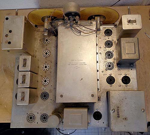
Photo above shows
the chassis before any cleaning. Grease and dirt
combined with humidity and tobacco smoke,...yuk! |
Noise Limiter - Frozen Shaft
- Heat was used in combination with WD-40 to work the control
shaft loose. It took several applications but finally it was
working normally. I noticed that someone had turned the NL
control while the shaft was frozen and actually rotated the
potentiometer. I had to dismount the RF Gain pot and the NL pot
to get everything oriented correctly. Ultimately this pot tested
as
defective and had to be replaced with an original NL pot that
was harvested from the NC-183D parts set. Luckily, the NL
circuit hadn't changed in the evolution of the receiver model so
the pots were identical.
Replaced the Filter Choke
- I removed the open choke and installed the spare unit that had
come out of a HRO-60, it was the same part number. Since the
original was open, it's possible that its open condition
actually "saved" the power transformer from subsequent damage from those "let's plug it
in and see if it works" types that expect miracles from
three-quarters of a century old components.
Cleaning
- The entire chassis was filthy. Most of the
greasy dirt came off fairly easily using WD-40 followed by Glass
Plus. I found that just Glass Plus worked somewhat better on the
smoke contamination. The chassis is high-quality cadmium plated so it cleans up nicely. I used
a brass bristle brush with lots of Glass Plus. Since the brass
is softer than the nickel it only removes dirt. The aluminum
pieces can only be cleaned using an acid brush or similar
soft-bristle brush otherwise the aluminum will be scratched. The
stamped part numbers on the individual components used a very durable ink that is resistant to
Glass Plus which is nice. Some severe tobacco staining required
denatured alcohol, probably to break-up the tar component of the
cigarette smoke deposits. That was then again followed by Glass
Plus cleaning. |
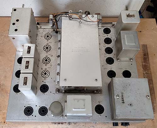
Photo above shows
the cleaned chassis but
without dials mounted or tubes installed. That's
the HRO-60 filter choke installed, it's the
exact same part number as the original choke. |
|
Tuning Condenser Cleaning
- This area had a lot of grease along with tar and nicotine contamination. I
removed a lot of it using Glass Plus. For the most stubborn
contamination I had to switch to denatured alcohol. I had already
removed the plastic dials but, if denatured alcohol is going to
be used, you also have to avoid any contact with the ink
lettering or ink-stamped part numbers. The ink is tolerant of
Glass Plus but it probably wouldn't survive too much denatured alcohol. I used an acid brush
to flush the tuning and bandspread condensers, the ceramic
insulators and the area with denatured alcohol followed by Glass
Plus. Really disgusting how the "smoker contamination" permeates
to all areas of the top of the chassis. Underneath the chassis isn't too
bad, minor contamination where the dials come through the
chassis,...probably because it's at the front of the receiver,
it's a large opening and it's nearest the smoker-operator. So,
the underside just required a little "spot cleaning."
In addition to the smoker's contamination, sometime in the past
someone "greased" absolutely every "moving part," including the
band switch and the rotor
contacts on the tuning condensers. Grease was actually slathered
everywhere and that makes cleaning even more difficult. |
|
Audio Gain Pot -
This was a "splined split-shaft" replacement that didn't
allow mounting the knob correctly. Easy to replace,...or so I
thought. Examination of the NC-183D "parts set" revealed the
change in that receiver when compared to this earlier NC-183.
The AF Gain pot incorporated the AC power switch on the NC-183D,
so I had to go to the "used pot box" for a proper type of
potentiometer. I found a couple of 500K Audio taper pots that
looked very much like the original style (these were Clarostat
types.) I selected the one that tested the best and installed
it. I'm not sure what the original pot's taper was since it's
not mentioned in the parts list. The Audio taper will allow a
slow increase in audio gain to about 60% advanced, then a rapid
increase in gain for the remaining 40%. It makes the actual
"listening-level of volume" easier to adjust. Photo
right shows the new Audio gain pot installed.
|
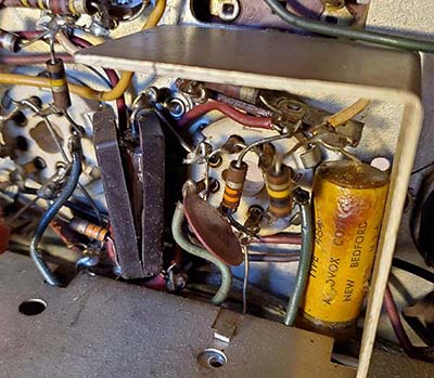
The .05uf
600vdc capacitor is split-open. Note the
ceramic disk is connected from
suppressor-grid to ground - not an
original component. |
Replacing
Capacitors - There are thirty
paper dielectric capacitors that will need to
be replaced. There aren't any weird values, just
the typical .1uf, .01uf, .05uf and one .25uf.
The .05uf capacitors, of which there are four,
are the rectangular brown molded plastic body types.
The photo to the left shows one of the four
.05uf 600vdc bakelite capacitors that split
apart (3 or the 4 are split-open.)
The other capacitors are the typical Aerovox
brand tubular wax-covered types. The mica
capacitors are usually only replaced if found
defective. There are five electrolytic
capacitors. The filter capacitor is a dual
multi-section both 10uf at 475vdc. There are two
cathode bypass electrolytic capacitor and one
addition power supply (bias line) electrolytic.
There's a .1uf capacitor across the filter choke
to somewhat tune the filtering (parallel LC at
resonance is a high Z, probably tuned
for 120hz.) I'm not going
to bother with "restuffing" the original
capacitor waxed-cardboard shells. I'm going to use orange drops for all of the
replacement capacitors. I've never had any trouble
with the polyfilm "yellow jackets" but their
bright yellow color and small size make any
recap job look like the cheapest parts available
were used. Orange drops aren't too much better
in the "looks department" but the Type 715P uses
polypropylene as the dielectric material and
they are "more accepted" by rebuilding
technicians for a recap job because of their
reputation of quality. Photo right shows under
the chassis before any capacitor replacement.
The three "as found" replacements are easily
spotted in the photo (the blue cap next to
the replacement Orange Drop is the wrong value.
The Orange Drop is also the wrong
value,...hmmmm,...hamster junk box "close-enough" parts.) |
|
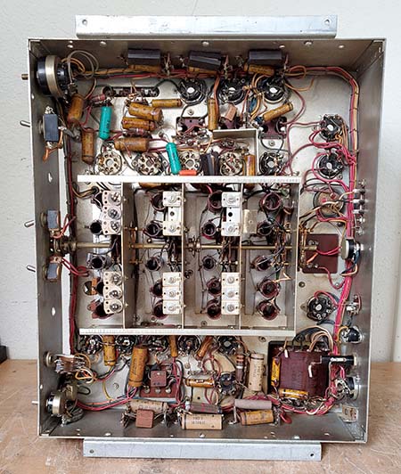
Under the chassis
before any rework |
|
Jan 16, 2024 - Need Capacitors -
Despite a long search, I couldn't come up with
enough orange drop capacitors on hand here to do the recap
job completely.
Although I found almost enough capacitors, they
were a mixed assortment of new and used vintage Sprague,
not-so-new SBE, new CDE and
other types of orange drops that "sort of matched"
but really didn't. I'd rather install all new
CDE Type 715P
with polypropylene dielectric for all of the
capacitors than to use a mix of different types
and vintages.
The order will be placed tomorrow (it was,
Jan 17.) So, since
I'll have a few days, I'll take a look at all of
the resistors under the chassis. I'll replace
any that are over 25% out of tolerance. I'll
also have to do some work on the
cabinet. I noticed that the lower front panel is
"dished in" probably from the poor packing job
and resulting shipping issues (the seller
used FedEX as the packer - big mistake!) With the knobs
installed, this bend isn't too noticeable but it's
there,...along with a center bottom vertical
bend where the center of the front panel was
"pushed in." These are minor bends that aren't
very noticeable unless you know they're there.
Then they're obvious. Also, when the cabinet is
assembled the misalignment is then very noticeable
and is due to the bent metal.
I'm pretty sure careful "bodywork" can
straighten out the cabinet without damaging the
paint. The back panel and hinged top also need a
little "bodywork" since a right top back corner
bend is causing the lid to not set straight in
the lid-well when the cabinet is fully
assembled. I'll also fully clean the cabinet
which actually looks really good until it's
examined closely and then the smoker's residue
is apparent. Straight and clean
should be an improvement that should be
noticeable. |
Jan 18, 2024
- Checked resistor values - All checked within
25% except some of the 470K which is normal for
the NC-183. I checked the NL pot that had been
twisted with the frozen shaft. It doesn't
measure as expected, in fact, it appears to be
open which isn't too surprising after its other
problems. I checked the NC-183D schematic and
its NL pot is identical to the one used in the
NC-183 (100K with DPST switch,) so I'll harvest
that one out of the "D parts set" The other potentiometers tested okay.
Touch-up
Paint - I bought some Testor's model enamel paint (small
glass jars) to mix up an exact "touch-up" paint
for the very light gray with a touch of silver.
I had to do the same thing for RACAL's
"Admiralty Gray" which is actually a very light
green color. The approximate mix for the NC-183 & NC-173
light gray with a touch of silver is
Machine Gray
(5 parts) + Silver
(4 parts) + White
(3 parts) + Yellow
(1 part) + Brown
(a dab.) Use a mix of gloss and flat paints to
end up with semi-gloss (3 gloss to 2 flat is
about right.) The mix-hue when wet has to be
just slightly lighter than the cabinet paint
because most paint colors dry slightly darker. The mix
will get you close but each cabinet has aged
differently so you will have to vary the mix
slightly to match. Also, match using sunny
daylight from a window or two for ample natural
light that won't skew the colors. Don't have
any lamps on,...lamps tend to skew the color
match. I didn't apply
the touch-up paint until after the receiver was
completely reassembled. The last photo in this
restoration write-up section shows the NC-183
after the rebuild was completed and the touch-up
paint applied. |
|
Jan 19, 2024 - Noise Limiter Control Replacement
- Harvested the Noise Limiter control
and switch out of the "parts set" NC-183D. The
NL control was almost identical to the old pot
and switch that was in the NC-183 with the
exception that the switch that had a slightly
different orientation but the function was the
same. I cleaned all of the terminals with solder
wick and then tested the pot and switch to make
sure it was a functional unit. To install the NL
switch is fairly difficult because of its
location in the front corner of the chassis
right next to the bottom with very little
clearance and with the wiring harness directly
underneath the pot. I had the NC-183 chassis up
on one end to allow easy viewing of the NL pot
location. The RF gain control has to be
dismounted and pushed to the side out of the
way. There's a 270K CC resistor that connects to
the center terminal on the NL pot that has to be
unsoldered along with the .1uf capacitor
connected to the NL switch to actually be able
to move the NL pot out to be able to unsolder
the two wires that connect to the NL pot and
then the one wire that connects to the NL
switch. Once disconnected the old NL pot/switch
was removed. The wire leads were reconditioned.
I had to rearrange the wiring harness to have
the new NL control actually fit without smashing
down on the harness when mounted. Once the NL
pot fit in place correctly, the wires and
components were connected and soldered (except
for the capacitor which will be replaced during
the "recap" part of the rebuild.) The RF gain
pot was remounted. Installing the NL pot took
about an hour because of the "tight
quarters area" and
trying different arrangements of the harness
until one was found that worked. |
Jan 20, 2024
- Cabinet Work - Since the
capacitors still haven't arrived, I moved on to
the cabinet. The index fiducials are removable
since they are mounted with two screws. There
are also two dial guides that are held in place
with two screws each. The plastic window with
the band indicators is mounted with four screws
and nuts along with a rectangular metal spacer
on each side. Removal of this hardware allows
taking out the plastic window that is actually
one long piece of thin and flexible plastic. As
expected, the plastic window was extremely dirty
and had lots of smoker's residue. I had to use
Glass Plus to clean both sides of the plastic
window three times to remove all of the
contamination. The cabinet was cleaned inside
and out with Glass Plus. I had to use a
soft-bristle brush to scrub the areas that had a
lot of smoker's residue. After two cleanings,
the cabinet looks pretty good. It will need to
be "touched up" but not extensively. The most
serious problem is the front panel bend.
Straightening the cabinet to be square without
damaging the paint (any more than it already is
damaged) will require using thin padding (I use
heavy stock paper) against the paint to protect
it when the bodywork is performed. I taped the
paper padding to the front of the receiver using
blue masking tape. I used a piece of hardwood as
the "anvil" and another piece of hardwood for
the "dolly." A few times I had to use the hammer
directly on the inside metal of the cabinet to
get it to bend correctly. It took about 15
minutes to get the cabinet straight. I also had
to work on the rear panel but these bends were
easily straightened using other techniques. I
put the cabinet together to see how everything
fit now that it was straight and no problems
were encountered when threading in the screws.
The cabinet does set straight and looks
"square" now. |
|
Jan 21, 2024 - Miscellaneous Work - Disassembled both
to the pinch-wheel drive assemblies to remove
all of the grease, dirt and other contaminates
that were all over and inside the assemblies.
Cleaned everything with denatured alcohol and
then lightly lubed the bearings with red wheel
bearing grease. The actual pinch-wheels have to
be completely clean to grip the plastic dial
perimeters. The dial perimeters also have to be
thoroughly clean. Reassembled the drives and
they are ready to install after the capacitor
rebuild. I also reinstalled the plastic dial
cover. The dial index fiducials were cleaned and
needed just a little straightening before
installation. The dial guides (these keep the
dials from rubbing against the dial index fiducials) were
cleaned, adjusted and reinstalled but these have
to be removed before the chassis is reinstalled
into the cabinet. The
pinch-wheel drives, the dial index fiducials and the
dial guides all have to be adjusted after the
chassis is installed into the cabinet.
|
Jan 22, 2024 -
More Cabinet Cleaning - In some
types of light, I could see there was still that
yellowish smoker's residue on the cabinet. I
wouldn't recommend the following treatment unless it's tried on
someplace out of sight first. Denatured
alcohol seemed to be the best for removing the
most difficult of the smoker's residue. I tried
the inside rear panel first and the smoker's residue came
off and, most importantly, the paint was not affected
at all. I continued on,
cleaning all sides of the cabinet using
denatured alcohol and clean paper towels so I
could see what was coming off and it was always
the yellowish brown color of tobacco smoke. I never saw any indications
that the paint was being affected but I'd say
that 99% of the smoker's residue is now removed
from the cabinet.
Jan 23, 2024 - Degreasing
- I used DeOxit to thoroughly clean the band
switch. To make sure that all of the grease was
removed from the contacts, I used a small paint
brush to apply the DeOxit just where it was
needed. There were places that had grease
applied that needed more detailed cleaning, like
two or three brush applications, to
remove the white-colored grease that had been used (unbelievable!) The
Tuning and Band Spread condensers were also
"greased" at all of the rotor contacts
and required additional cleaning.
I had to use DeOxit and a brush to clean the rotor
contacts that had been greased with that old white grease. I
sparingly relubed the Tuning and BS condenser
ball bearings with red wheel bearing grease
worked into the ball bearings ONLY.
I wondered about this white grease smeared
everywhere and
remembered that back in the days of TV repair shops,
older TVs had a revolving turret,
channel-changing Tuner. There was a product then called "Tuner Grease" that was supposed to be
applied to the TV-tuner contacts. It was
supposed to decrease the wear, ease the
"channel-changing effort" and provide better
contact. Anyway, that might have been where the idea for smearing the grease everywhere in the receiver
came from.
|
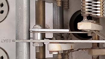
The bi-metallic
temperature compensation device for the
Local Oscillator is behind the LO tuning condenser stator.
This device was only used on the NC-173
and the NC-183 receivers. The NC-183D
used a converter 6BE6 tube and a
different method to control f vs temp
drift |
|
|
Jan 23, 2024 - Recap Job - The parts came
in today so I started the recap job. Eleven caps
installed so far. It should be more but three
times (so far) I've had to completely rebuild a
solder joint where a replacement resistor was
just wrapped and soldered with old lead just
clipped. Sloppy work that needed to be
corrected, so it takes a lot more time. Each
replacement capacitor lead is installed inside the
terminal hole. This requires removing the old
capacitor lead and usually "wicking" a lot of
the old solder out. Then the new capacitor lead
can be installed correctly and soldered
properly. Takes a lot longer but it then looks and
functions like a
professional did the rework (nothing looks
more like an "amateur job" than using hook
splices to install replacement parts.)
More caps
replaced - I found that the plate
load bypass on the Mixer had a replacement
plastic molded cap that was 0.1uf but the value
shown in the manual indicated that it should be
a .05uf. Additionally, one end of the plastic
0.1uf hadn't even been soldered. This plastic cap was
replaced with a .05uf 600vdc Orange Drop. The
two IF amplifier screen load resistors were
obvious replacements being 2W resistors. But,
even these 2W resistors had swollen from being
overheated by the original leaky bypass capacitors
that were still in the circuit (if the
original 1/2W resistors burn up,...replace them
with 2W resistors that can tolerate the capacitor leakage
current,... but don't change that
cap! No excuse for this incompetence but I've found it
many times in
various rebuilds.) I replaced the resistors with the
correct dissipation CCs and the
capacitors with new Orange Drops. There were three .0068uf ceramic
disk capacitors on the suppressor grid to ground
on the two RF amps and the Mixer
that were removed since the suppressor grid is
already grounded and these disks aren't shown on
the schematic.
Jan 24, 2024 - Completed
installation of all 30 of the Orange Drop
capacitors. Every joint was unsoldered, cut
leads removed, the terminal solder wicked out
and then the capacitor lead installed and
soldered. There were no "hook splices" used. I
found that one original bypass capacitor on the B+ line had just one
end cut. I didn't check but it's probably
shorted and that was a quick way to get the
receiver semi-working again (the ham's aversion to actually replacing
THE defective component.) I found that many
of the resistors were replacements that were
installed with the typical "wrap and solder"
technique or the even lazier approach of
tack-soldering. This type of poor workmanship is
often found on receivers that
were maintained by the ham-owner.
I tested the
electrolytic capacitors by lifting one end and
then using a capacitance meter. One of the 25uf
capacitors tested at 15uf. The 10uf tested at
17uf and the other 25uf tested at 40uf. The
filter electrolytic can't be checked unless it
is disconnected from the choke. The choke ties
the two positive terminals together and the dual
unit has a common negative. In essence, the two
sections are in parallel. Tested in this manner,
I read 15uf which seems to indicate that the two
sections are low in capacitance. However, since
I've already replaced all of the paper
dielectric caps, I'll go ahead and replace the
five electrolytic capacitors too (since the
receiver chassis doesn't look original
anymore, anyway.) |
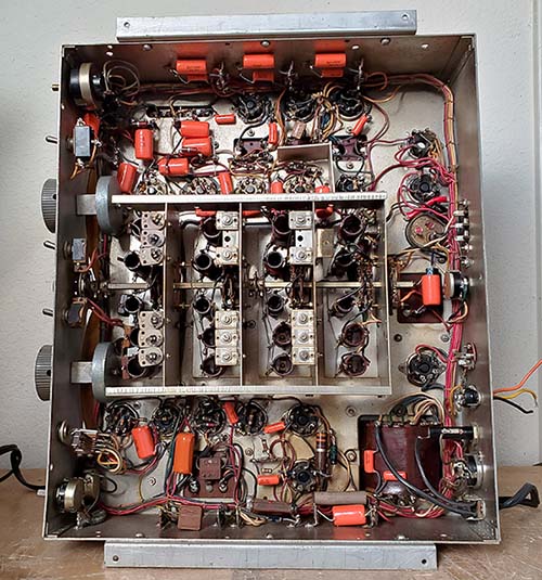
Under the chassis after the recapping job. For
some reason, the Orange Drops look pretty
good,...well,...better than Yellow Jackets |
| Jan 25, 2024
- Installed a vintage two-conductor AC cord with
molded plug. This allowed me to perform a test
on the power transformer. I installed a #47 lamp
in the S-meter lamp socket so I'd have a pilot
light of sorts. I switched on the AC and the
lamp illuminated indicating I had 6.3vac from
the power transformer. I measured the 5vac
rectifier winding and it was okay. The HV
winding was about 345vac each side of CT which
is okay. I left the power transformer running
for about 15 minutes to see if it got hot but it
remained cold to the touch, which is good. I
installed new 10uf 450vdc electrolytic caps for
the filters. I didn't remove the original
capacitor but I did disconnect the two positive
wires on each terminal. These "pairs" were then soldered together with a
lacquered sleeve installed over the joint. I
then connected the two 10uf electrolytics into
the circuit and placed them in a way they were
somewhat hidden and not obvious.
Interestingly, the NC-183D changed the filter
capacitor values to 40uf for each electrolytic
capacitor in the multi-section unit. The three
bias filter
capacitors were installed in the same manner as
the originals. I had to use a slightly higher
value on the negative bias voltage line, the
original was 25uf and I installed a 47uf 50vdc
instead. The two cathode bypass electrolytics were
the original values of 10uf for the 1st AF amp
cathode and 25uf for the P-P 6V6 cathodes.
Unbelievably when I was looking in the parts
bins for fuses and plugs, I saw a little three pin
plug laying in one bin. I turned it over and it had two small
diameter pins and one large diameter pin. I
tested it in the NC-183 and it was a perfect fit
for the audio output connector socket (that
was a lucky find,...I didn't know where I was going to
find that type of plug.) |
Jan 26, 2024 - Powered Up -
Tested tubes to install into the NC-183. Only
about half of the tubes were good with most of
the discarded ones testing far below minimum
acceptable. With all good condition tubes
installed, I could now power-up the NC-183 and
see what other problems might be encountered.
Now, I didn't have the dials installed, so I had
to just guess where I was tuning but going the
AM-BC band made that easy. I connected an 8Z
loudspeaker to the audio output and a ten foot
long wire for the antenna. I had the receiver's
AC connected to a Variac so I could bring the AC
voltage up relatively slowly (like soft-start)
to watch the rectifier and see what would
happen. To my surprise, there was a small arc
inside the 5U4GB rectifier that didn't do any
damage. I tapped the 5U4GB envelope and it arced
again. Well, that tube might have checked good
on the TV-7 but it was obviously defective. I
installed a 5U4G tube that had tested good and
had been with the spare tubes included in the
receiver purchase. This rectifier worked
correctly and I could now hear background noise
coming through the speaker. I switched from Band
C down to Band E which is the AM-BC band. I
tuned around and heard an AM signal but it was
weaker than expected. I adjusted the Trimmer and
that helped a little. Then I remembered all of
the grease I had to remove from the band switch.
I "rocked" the band switch and suddenly the
signal went from S-3 up to about S-9. The audio
was fantastic sounding even though the speaker
was a little eight-inch test
speaker. I tuned around the AM-BC band and heard
all of the normal daytime stations. I checked
the B+ at +345vdc at the second filter capacitor
which sounds about right. I couldn't get an
output on the 500Z output but the 8Z worked
fine. In checking closely I found that the soldered
connection at the output transformer on the 500Z
terminal was a cold solder joint,...and it
looked original. Anyway, resoldering the
terminal got the 500Z output working fine. Next,...the dials. |
| Jan 27, 2024 -
Pinch-wheel Adjustments - Getting the pinch-wheel
drive to work with the dials is more difficult than one
would think,... especially after a complete disassembly.
Thoroughly cleaning the pinch-wheel drive assemblies of
all of the excess grease left the excessive clearance
obvious in the tuning. Originally, National probably
used damping grease but with white grease slathered
on the assembly all of that grease had to be cleaned first. The
excessive clearance can be compensated for with a
damping grease like Nyo-gel which is a very "sticky" grease
with lots of damping ability. Only the 1/4" diameter
shaft through the front bushing needs Nyo-gel and then
only use it sparingly.
The next issue is the height of each dial above its
associated pinch-wheel. This is controlled by the height
of the front frame of the tuning condenser assembly
above the chassis top surface. The studs and nuts that
tighten the front of the condenser assembly in place
were loose when I first inspected the receiver. In
tightening them, of course, I didn't have the dials
installed so I didn't know if the height was
correct or not. Later, with the pinch-wheel assembly mounted, then the
engagement of the dial rim into the pinch-wheel is
governed by the height of the front of the tuning condenser which is
adjusted with the two top nuts on the two front mounting studs which sets the height and the nut under the chassis
that locks the mounting in place. Unfortunately, when
assembled, the
pinch-wheel flywheels
block access to the bottom nuts so the flywheels have to
be removed before the bottom nut can be tightened. But,
the compression of the pinch-wheel depends on the
flywheel being mounted, so you can't test the drive
unless its fully assembled. This
makes the entire adjustment a
little more difficult than it should be. I had to do one
dial and pinch-wheel assembly at a time and set the
tuning condenser height one side at a time. It's a very
slight adjustment difference between the dials slipping and the
pinch-wheel gripping effectively. Trial and error will
eventually find the correct setting. It took me two
times on the Main Tuning and four times on the Band
Spread, so finding the correct settings will require a
little bit of patience.
NOTE: It's also possible to move the
mounting of the pinch-wheel bearing a little bit. This
method can be used if the condenser height is about right
and just a slight adjustment is all that's needed.
Sometimes the tightening of the mounting nut will change
the angle of the pinch-wheel assembly slightly so you do
have to watch exactly what happens as you tighten up the
nut. |
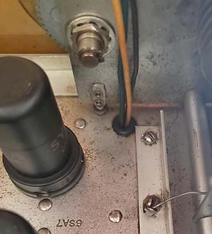
The
tuning condenser assembly front mounting stud and
"height setting" nut on the Band Spread side of the TC
assembly. |
| Quickie Testing
- With the receiver now having dials and
tuning knobs (but no index fiducials since those mount in the
cabinet,) I tuned around the 20M band. It was Field Day,
so lots of activity. I tried 40M and also lots of
activity. Tuned WWV on 15mc to get an idea of the audio
response. Lots of lows in the audio are possible with
strong signals but since I was using just a ten foot long wire
as a test antenna, not too many strong signals. I
noticed that the dials could probably stand more
illumination because of their darkened condition. Since
the lamps are quite a distance away from the dials, I
replaced the #47 lamps with #44 lamps to get the dials a
little brighter looking. The S-meter can only have a #47
since the lamp is very close to the scale. I tried a #51
round bulb but the lamp holder won't push into the back
of the S-meter with the #51 installed.
Next,...installation into the cabinet which is more
involved than one would think. There are dial guides
that have to be installed after the receiver is in the
cabinet. These keep the dials from rubbing on the index fiducials. Also, the
index fiducials are also adjustable from
side-to-side for centering the index fiducial with the dial and
the receiver position in the cabinet.
Jan 28, 2024 - Cabinet Installation and Knob
Cleaning - Installing the chassis
into the cabinet isn't too difficult. The mountings
are the four bottom felt-cupped feet and the
chassis front is pulled flush with the inside
cabinet-panel wall using the dress nuts for the
Phone jack, the Send-Rec switch, the AVC-MVC switch and the Radio-Phono switch. Once
these are snugged-up then the back panel can be
installed. This has two screws that secure the
rear of the chassis to the back panel and several
screws around the perimeter to secure the back
panel to the cabinet. These rear panel screws
are all Philip's head sheet metal screws. It's
important that ALL screws and lock washers (if
originally used) are
installed. The cabinet rigidity depends on all
of the screws being present. With the chassis
mounted in the cabinet, then the dial guides are
installed. These mount with two hex head 6-32
screws and external-tooth locking washers each. The guides will have two fingers in
front of the dial and one finger behind the
dial. The guide prevents the dial from rubbing on
the index fiducial. |
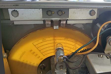
Dial Guide on Band
Spread dial. The two center hex head screws
adjust the position of the index fiducial |
|
Knob Cleaning - I never
tried this before,...but, after seeing commercials
for Dawn dish soap where a little crude oil-soaked duckling
is cleaned up and degreased with no ill-effects,
Dawn must be a gentle soap,...or so I thought. I
soaked the knobs in warm water mixed with Dawn.
The knobs were in the solution about 10 minutes.
When I took the knobs out, I noticed that all of
the "finger gunk" was gone from the knob
flutes,...and that was great. But, as soon as the knob
plastic began to dry, a white film and dullness
showed up. It was like the plastic had also been
"degreased." I've seen this happen with
phosphate-type cleaners before. I tried to
remove the white color using car wax but that didn't help. What did work was to
thoroughly work into the plastic "3'n'1" oil. I
used a terry-cloth and short bristle brush for
that part and then rubbed the oil into the
plastic with another terry-cloth until
completely dry. This seemed to remove the white
coating quite well and the dullness was replaced
with a slight sheen. I've seen the white coating
show up on National plastic knobs before (not
the old bakelite knobs, just the later plastic knobs) and
it's difficult to remove. It wasn't the
Dawn soap, but it's something in the plastic National
used for its knobs from the late-forties up well
into the fifties that reacts with either water
or high humidity. Probably knob cleaning with
WD-40 and a scrub bristle brush to get out the
"finger gunk" would have worked better. I usually follow WD-40 with Glass Plus.
Anyway, I won't be using a Dawn dish soap soak
again unless it's a metal knob.
NOTE: I
wanted to replace the TONE control knob because the
skirt was bent and loose. I found a correct knob to
salvage off of a junk National set. I cleaned this
salvaged knob with just
Glass Plus and a bristle brush. No white coating
developed, so Glass Plus is safe for cleaning these
types of National plastic knob grips. |
|
Jan 29, 2024
- Installing the lid isn't too complicated.
There are right angle stops on the hinges that
only allow the lid to go up to the vertical
position. The lid has to be almost closed to
insert the 6/32 screws through the rear panel.
Then the lid is put up vertically and the stops
will hold the screws in place. Then the nuts and
lock washers can be installed from the inside of
the cabinet. This completes
the rebuild of the NC-183 as far as the
mechanics and the electronics (except for
installing the bottom cover.) Now, I'll use the
NC-183 daily for an hour or so for a few days to
do a sort of "shake-down" and if no problems
crop-up we'll then proceed on to the IF and RF
tracking alignment. I listened today with the
Collinear Array as the antenna. Even 20mc WWV
was strong. Trenton Military on 15.035mc USB from
Ontario, Canada was easily heard. I switched over to a
Collins 270G-3 10" loudspeaker that really improved the
bass response. I listened to a couple of SW-BC stations
and the strong ones sound quite impressive. Jan 30, 2024
- I adjusted the position of the dial index
fiducials to exactly match the dial stops on the
gear drive and the position of the tuning and
band spread condensers set at full mesh. This is
the preliminary mechanical set-up that proceeds
any actual electronic alignment. I then checked
a few frequency marker stations and I was really
surprised at how close the electronic tracking
alignment already was. WWV 15mc was very close
and WWV 10mc was 100kc off. On the AM-BC band
all of the daytime locals were very close to
their assigned frequencies. The Band Spread was
set to the "SET" mark at 180 of 200 on the
logging scale. The receiver seems to be
performing much better than I would have
expected and that indicates that the alignment
is probably pretty close. Even the Crystal
Filter seemed to be working pretty well. When I do
the alignment in a day or so, I'll find out just
how close it really is. To eliminate the need of
flipping through the pages of the manual for the
adjustment locations, I made copies of the top
chassis layout and the bottom chassis layout.
These two pages aren't with the alignment
procedure in the manual so having loose copies
simplifies locating the correct adjustments
while performing the alignment. |
NC-183 Installed back in the
Cabinet |
|
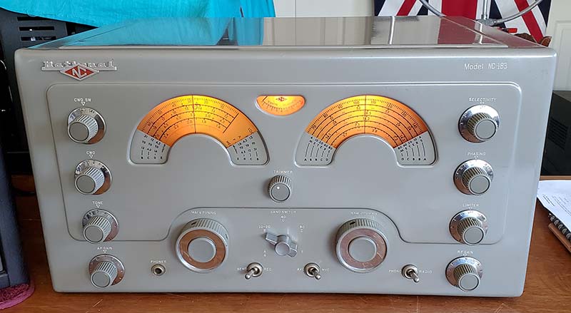
NC-183 SN: 241 0262
The finished receiver has turned out to
be an excellent performer. I've been using it "on the
air" and it has proven to be a dependable vintage ham
station asset. Production run #241 was probably the
third
of NC-183 receivers and that would put the build date of
this receiver around early-1949. |
Feb 1, 2024 -
Alignments - IF - The NC-183 IF seemed to be tuned to 451kc. I "rang" the Crystal Filter crystal
and it was resonant at 457.8kc, so the IF wasn't
really very close to where it should be. Using
457.8kc as the alignment frequency, I connected
the RF signal generator to the Mixer stator
through a .1uf capacitor. The IF and Crystal
Filter were aligned as specified in the National
NC-183 manual. Then the
Amplified AVC and the BFO were adjusted for
457.8kc. Before the IF alignment I couldn't get
the S-meter to respond much more than about S-4
on 15mc WWV, now it showed S-9+, so the IF was
certainly improved.
NOTE:
One thing I noticed had to do with my having
both the National manual and the Sam's Photofact
for the NC-183. The National IF alignment has
several steps specifically for the Crystal
Filter alignment that pays off with its proper
operation. The Sam's doesn't have a Crystal
Filter alignment procedure and just
instructs the technician to "peak" the
adjustments in the Crystal Filter at the IF
frequency. In fact, the Sam's doesn't even have
the procedure to "ring" the crystal to determine
the correct IF. If the Crystal Filter and IF are
aligned as instructed in the Sam's Photofact the
receiver will work okay but the Crystal
Filter won't operate correctly. Use the
National NC-183 manual procedure.
Alignments - RF Tracking - The RF
Tracking wasn't too far off. Just little adjustments to
get the dial indications to be very accurate. Since I
did the mechanical set up first and apparently nobody in the past
had gotten into the inductance loops for adjusting the
low end, just adjusting the trimmers accurately got the
entire tracking to be excellent.
Finishing Up
- The bottom cover was really greasy on the side facing
into the chassis. I had to use WD-40 and a brass bristle
brush to remove the grease. This was followed by Glass
Plus to clean the WD-40 residue. The bottom cover is
mounted with three sheet metal screws at the rear, one
sheet metal screw in the center and a 6-32 binder head
machine screw and flat washer in front. The photo to the
left shows the NC-183 after the rebuild. Note that the
dials, when illuminated, look bright and the
nomenclature is crisp. The red isn't as faded-looking
when the dials are illuminated. The photo was taken
after I did the "touch-up" paint job. The "touch-up"
paint was mixed as described in Jan 18th log "Touch-up
Paint" above. |
|
NC-183 Performance After the Rebuild |
|
Shortwave Listening - I connected the NC-183 to the Collinear Array antenna.
I listened for the Chinese Maritime Stations at 16.985mc
and heard XSG coming in pretty well. I didn't hear XSQ
which is usually the stronger station but hearing XSG
was a good sign since either one are
moderately difficult stations on 16mc (on Sunday
afternoon, I copied XSQ on 16.998mc about RST 579.) Listened to a few
SW-BC stations in the 19M band and the 31M band. I then
went to 39M and the SW-BC stations were extremely strong
almost pegging the S-meter. At 49M, only Radio Havana
seemed to be really strong but there was one station
that pegged the S-meter that must have been a Westcoast
USA SW station (religious BC.) Went to 80M and some of
the SSB stations required reducing the RF gain to "2"
they were so strong. Since I was listening to SSB, I had
the receiver in MVC and throttled-back the RF gain for
proper demodulation. There were two AM stations on
around 3870kc but they were not very strong but still
could be copied
Q5. I was listening around 1700hrs PST. Audio response
is fantastic on SW-BC, if the station is actually
broadcasting good audio (some shortwave stations don't.)
I did notice that on extremely strong SW-BC stations
slightly better bass response can be realized by going to MVC
then reducing the RF gain and increasing the AF gain. In
AVC, with the RF gain at 9.5, these SW stations have very
nice, broad audio frequency response although many of
the moderately strong stations are affected by QSB. I'm
using a Collins 270G-3 loudspeaker, so I might find even
better audio results from using a more "hi-fi" speaker. The
NC-183 is an excellent SWL receiver.
Ham Operation
- I've paired the NC-183 with the Johnson-Viking 1
transmitter. They are both approximately from the same
time period, 1949 to 1950. The antenna is the Collinear
Array. I had to set-up a DowKey relay to work
with the Viking 1 relay drive that is parallel with the
Plate switch and then to use the DowKey auxiliary
contacts to operate the remote standby on the NC-183. The Viking 1 transmitter
doesn't have push-to-talk so turning ON the PLATE switch
places the transmitter into operation and, via the DowKey,
places the NC-183 in standby. The DowKey T-R contacts
switch the antenna to the Viking 1 when the PLATE is
turned on. This particular DowKey has the spring-loaded
disconnect in the receiver-side coaxial fitting barrel as added
protection. >>> |

The Viking 1 with VFO and
the NC-183
station |
>>> The operational debut of
this station was on the
Nevada Vintage Mil-Rad Net on Feb 4, 2024. The NC-183
operation was flawless,...an excellent performing receiver. I had
to reduce the RF Gain down to about 7 and the AF Gain
was at 2 for the entire net since propagation was great and all signals were very strong. Even with the RF gain
at 7, the S-meter would generally show stations as
S-9+30db and the ambient noise level was S-3 with that
set-up using the Collinear Array on 3.974mc (0730hrs to
0900hrs.) I used the
Crystal Filter one time and it was effective on position
3 with a slight Phasing adjustment to eliminate some temporary SSB QRM
(proper alignment of the Crystal Filter makes it an
extremely useful tool in combating QRM, even in the AM
mode.) The rest of the
net was received with the Crystal Filter switched out. I
was still using the Collins 270G-3 speaker and most of the
time had the Tone set to "3" for excellent audio
response. The conclusion is that the NC-183 can perform
very well as a vintage station receiver on 75M. 40M
doesn't have very much AM activity. I only hear a
station or two, once in a while, up around 7.295mc. I
don't think using the NC-183 on 40M would present any
problems, especially if 40M CW was used for the
operations. There hasn't been any activity on 20M AM in
years. Bob K7POF used to have a daily AM net on 14.267mc
but that was almost 30 years ago. Nowadays, 20M CW operation
would be a possibility. On 10M AM it's difficult to tell
if you're having a QSO with an actual licensed ham
unless you can check QRZ during the QSO (and even then
you don't know if the callsign isn't being "bootlegged.") I haven't
operated 10M in over 20 years because of that type of
problem. To conclude the ham operation review, the
NC-183 is an excellent vintage receiver. It's easy to
set-up the remote standby. The sensitivity is very good
and the selectivity can easily cope with any of the normal QRM.
But, its fabulous audio reproduction is what really
stands out making the NC-183 an enjoyable asset to the
vintage ham AM station.
|
Wall Corner-Mounted Bass Reflex 12"
Loudspeaker - Feb 10, 2024
- I'm now using a wall corner-mounted bass
reflex speaker housing with the 12" loudspeaker
with the NC-183 receiver. I've used this
speaker-box before and was never really
impressed with its sound. It always seemed
shrill and lacking any bass. BUT, I'd always
used it with receivers that had borderline anemic audio, mostly
military receivers that needed a 600Z load, so I
had to install a matching transformer. That set-up definitely didn't
produce hi-fi audio. I've removed the 600Z to 8Z
matching transformer and the speaker cable is connected directly to the 8Z speaker voice coil. NOW, this bass-reflex box sounds
fantastic. Lots of
bass response and much more impressive sounding now that
it has some V-T audio power driving the Lo-Z VC of the speaker
directly. Another
important part to this sound improvement is the physical
location of the speaker. It's across the room about 10
feet from the operating desk and it's mounted up next to
the ceiling. The greater distance allows having the
NC-183 Audio gain somewhat more advanced and that results in
better audio power transferred to the speaker. The
greater height allows the bass reflex port that's on the
bottom of the housing to be about six feet above the
floor for unblocked bass response. The only
reason I might take the speaker housing down (temporarily)
would be to repaint it. Right now it's a hideous flat-finish dark
olive-drab. I think it would look a lot better painted
two-tone, light gray box with dark gray grille-work (although originally it was brown,...that's
right,...in a moment of mil-rad weakness I painted it OD.) The
corner speaker shown in a before and after -
when it was OD and now finished light gray and
black (completed Apr 4, 2024.) |
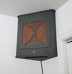 |
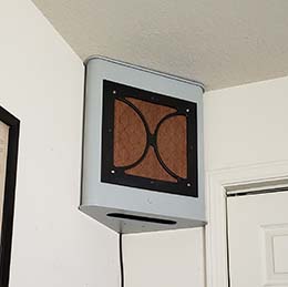 |
|
| SN:
241 0262 Revisits the Workbench
- Feb 12, 2024 - This is common with
rebuilt receivers that are actually used after the
rebuild as either the
ham station receiver or for serious SWLing. As the
receiver is used over and over, minor problems are
noticed that maybe didn't show up during test and
alignment or maybe it was thought the minor issue would
clear up after the receiver got some hours put on it.
But, most of the time, if the receiver is really a fun
one to use, then there's enough curiosity to investigate
and find out what's causing the minor (but annoying) problems. Here's what needs
to be looked at during the revisit. Fixes are
described in italics. UPDATE: Feb 15, 2024
- Problems 1, 2 and 3 were easily repaired but problem 4
was proving difficult to solve - but the solution came
as a complete surprise.
1. L21 IF Transformer
Secondary (Output side) & NL Control/Switch
- The peak adjustment on this was very shallow and a
barely noticeable change in output level regardless of
changing the position of the slug. Since I had the AVC
on and was using the S-meter for peaking, the AVC action
might have been controlling the final IF output since it
goes to the detector and AVC line. This output also goes
through the NL pot (that was replaced but was still
causing problems by attenuating the signal unless the ON-OFF
switch was jiggled around.) Since I did see
a small peak, I didn't investigate at the time. On the NL control,...by exercising the
NL control, the NL function started to work but the NL
switch function is still problematic. Both the NL pot
and switch should have been cleaned with DeOxit and I
didn't do that. Spraying DeOxit into the NL pot access
hole corrected the problems in both the pot and in the
switch. NL and switch operation are normal now. To test
the L21, I connected a VTVM to the diode load and input
a 457.8kc signal to the Mixer grid. I adjusted L21 and
it behaved exactly as it should, although it was
slightly off peak. I peaked the IF to 457.8kc (the
Crystal Filter's crystal f.)
2.
Crystal Filter switch
noisy - I forgot to pull the side cover and
clean the Selectivity switch with DeOxit when the
receiver was all apart. The switch has pretty much
"self-cleaned" since being operated often, but I really
should have used DeOxit on the switch and inspected the
inside of the Crystal Filter assembly. The inside cover
is easily removable while the receiver is in the
cabinet. There are six hex head screws to remove and
then the cover can be taken off. There aren't any studs
on the cover. There's quite a bit of clearance but the
6J5 LO tube and the 6SA7 Mixer tube can be removed for
better access. This was a very easy task. It took
about 15 minutes total to remove the cover, brush out
loose dust, spray DeOxit on the switch and the air
variable, clean the chassis area and reinstall the
cover. Works noiselessly now. Also, the .250" diameter
hole near the front right corner of the Crystal Filter
top cover is an access hole to allow spraying contact
cleaner on the switch. I didn't know that until I
removed the side cover and saw that there was no other
reason for that hole.
3.
Band E low
sensitivity - I checked this earlier and
couldn't really find anything. I'll have another look.
The only component in the AM-BC that is unique to that
band is the 200pf antenna coupling capacitor and it
checks okay. There's no visible damage to the Band E
antenna coil either. Well,...that's what I thought
but this did turn out to be a burned primary winding on
the Band E Antenna coil. The burned area was not readily
visible and a dental mirror was necessary
to actually see the burn. How it burned with the C
isolation is a mystery. The best "fix" would be to
salvage the Band E Antenna coil L5 from the parts set
NC-183D but to remove the Band E Antenna
L5 coil would require removal of the back of the RF coil
box, removing the band switch shaft and unsoldering a few wire connections
including the TC buss wire to the tuning condenser.
The mounting screws for the coils are
located on the bottom side of the assembly plate that is
also the rear side of the RF coil box. I'd have to do
that entire removal on both receivers to salvage the
coil and then install it into the NC-183. Since it's just the AM-BC band that really isn't
listened to (and would only be used for demo purposes)
here's the easiest fix,... I wound a small coil on a
rubber grommet that I used as the coil form. The grommet slips down inside the Antenna coil.
I only had to disconnect the coupling capacitor which
was then connected to one end of the new coil and the other
coil end was connected to the A2 coil terminal. With the
receiver turned on, I positioned the new coil for the
best signal response looking at the S-meter. This fix
isn't noticeable (unless you know it's there and looked down the coil barrel) and
the end result is that Band E has just about normal
sensitivity now. With burned primary, KOH 780kc was S2
with the test antenna. With new primary coil, KOH 780kc is
S-6 with the test antenna and runs S-8 on a larger outdoor antenna.
If I was really OCD, I'd remove just the burned primary
coil on the original coil form with it still mounted.
Then I'd just wind a new primary coil on the original
form. Since there are only maybe 30 double-layered turns
of ~ 32ga. enameled magnet wire for the primary coil, it
really wouldn't be too difficult. I may replace the
grommet-coil later if I feel obsessed with an uncontrollable
compulsion to do so.
UPDATE: Mar 23, 2024 - On a "183D parts
set" I discovered that it is possible to unscrew the
individual coils in the Antenna section. The leads can
be cut and then the coil unscrews to remove. There's
a tapped 6-32 hole in the brass coil retainer and
a screw under the coil mounting plate. The screw is long
enough that it doesn't "drop through" the hole in the
mounting plate, so a new coil can then be screwed in
place and connected up. I've already removed a good Band
E Ant Coil L5 from a late-build ''parts set" NC-183D.
However, I soon discovered that there was a redesign on
L5 with the NC-183D that did away with the capacitive
coupling from the Antenna Input to the primary. This was
replaced by a direct connection and a huge primary
winding that must be five or six layers. It might have
been due to the change in RF amplifier tubes from the
6SG7 used in the NC-183 to the 6BA6 used in the NC-183D.
So, the NC-183D L5 would work since the larger primary
winding isn't that
critical of a change,...more
to come when I remove the original L5 for close
examination. UPDATE: Aug
6, 2024 - NC-183 is on the bench and
ready to install the L5 from the "parts set" NC-183D.
The "D" L5 terminals were cleaned of cut leads and
solder. The wires were removed from the old L5 and it
could now be un-screwed from its mounting screw. The
terminals are slightly different on the "D" L5 but the
receiver wires would still easily reach. Nothing holds
the mounting screw in position so I made a small wooden
wedge that I installed under the coil chassis to hold
the L5 mounting screw tightly in position. Then the "D"
L5 was screwed in place. Since this isn't the way the
coil was originally installed, naturally, when tightly
mounted, the terminals didn't line-up correctly. I had
to leave the "D" L5 slightly loose to have the terminals
line-up where they should be. Next, the wires were
soldered to the "D" L5. The old L5 had the primary
capacitively-coupled to the antenna input. But, the
NC-183D is directly connected and the "D" L5 has a much
larger primary winding, so I removed the capacitor and
connected the primary directly to the antenna input as
if it was installed in a NC-183D receiver. I used a
solid wire to replace the capacitor to provide some
"stiffness" to the L5 mounting. Tested the "D" L5 by
tuning in KOH 780kc. This station was running S2 with
the original burned primary and about S-8 with the
make-shift coil inside the L5 coil form. Now, KOH 780kc
just about "pegs" the S-Meter using a 50ft test antenna.
S-9+40db. Antenna Trimmer works normally. I still have
to try AM-BC on an outdoor wire antenna.
4. Instability on
Band B - I thought this was the BFO but
actually it's the LO that's wobbling around BUT at first
it only seemed to happen on Band B. Band C seemed "rock
steady" but, as I did more listening, the instability
was apparent on all bands. Probably something in the LO section
or with some of the connections. First was to install another
6J5 LO tube but I got the same instability. I resoldered some connections
that involved the +150vdc regulated voltage. I also
replaced the 0D3 regulator tube. The best results were
when I sprayed the band switch with DeOxit (instead of
brushing on the DeOxit) and then rotated the band switch
several times in both directions. The other part of the
LC for the LO is the tuning condenser. The NC-183 has a
mechanical bi-metallic compensating capacitor on the LO
circuit that has to be set-up correctly and be tightened
to prevent its movement after calibration. This
compensating C wasn't tighten and, in fact, was very loose
and "flopping around." Also, typical staff-tech work, the lock washer had been left out at some time in the
past. The entire comp-C was oily and dirty. I cleaned it
and recalibrated it (.020" clearance between the brass
end and the stator contact.) Reassembly included the
lock washer. While I had the cover off, I went ahead and
again cleaned the Main Tuning and Band Spread condenser
rotor contacts with DeOxit. I noticed that the ceramic
tube sockets (front end tubes) pin contacts were spread
quite a bit so I used a couple of tools to push the pin
contacts back tight. I resoldered a few more joints that
looked bad. On the LO tube socket, the 47K resistor was
a replacement that was just "wrapped and soldered" so I
removed, checked its value again, cleaned the tube terminals and reinstalled the
resistor correctly. So far, the instability has not
changed and is still present. It's going to take
isolation and substitution to determine what's causing
this instability. First, the BFO needs to be eliminated
so,...TEST/ISOLATE BFO - I unplugged the BFO tube
and connected the RF signal
generator through a 200pf capacitor to act as the BFO. Set sig gen to 457.8kc and
tuned the receiver to 10mc WWV. The instability was
still there,...so it isn't the BFO. TEST/ISOLATE
LO - Using the same RF signal generator I
substituted it for the LO by pulling the LO tube and then
coupling the RF generator into the Mixer. The RF
generator is set 455kc above the tuned frequency so for
10mc WWV, the RF sig gen was set to 10.455mc. The BFO tube was reinstalled and the BFO switched on. 10mc
WWV came in as expected and the heterodyne of the BFO
was apparent. I listened for quite some time. I never
heard the instability at all. There was the slow linear
drift that would be expected but no erratic changes in
the BFO heterodyne which indicates that the instability
is almost certainly in the LO circuit. I did a lot of
other things that didn't fix the problem but finally I
moved the receiver out of the workshop and into the ham
shack. The stability problem seemed to be gone. As the
"station receiver" being "powered up" and
operated for about
an hour and a half it was noted that,...when the receiver has only been on for
a few minutes, the LO/BFO still drifted quite a lot. But, after about 15 minutes of operation, the LO/BFO
remain perfectly steady for the rest of the net.
UPDATE: Apr 3, 2024 - Solution? I was having exactly
this same problem of instability with a NC-183D I was
working on. I tried a few different things that didn't
work and then I kept thinking it was too much of a
coincidence that the NC-183D was
behaving exactly like the NC-183 had behaved and the
NC-183 problem disappeared when the receiver was moved to the ham shack.
So, I moved the NC-183D to the ham shack and the
instability problem disappeared,...same as with the NC-183. Hmmmm,...this means the problem is in the workshop and
is probably an unstable AC line maybe due to a defective
AC power strip, a defective AC outlet or maybe the AC line breaker. More checking of
the workshop required. Not using the power strip. Plug
directly to AC outlet and problem goes away. Defective
power strip. |
|
Restoring NC-173 SN: 173 2821
If this NC-173's serial number
follows National's usual encoding, production run 173
would have started before the last of the black-box
HRO-5A1 and the HRO-6 receivers were built (run 184.) It
would be before the last of the NC-2-40D receivers (run
183) and would be before any of the HRO-7 receivers (run
189 was for the first HRO-7 receivers.) National didn't introduce the HRO-7 until
August 1947 and the NC-2-40CS receivers were still being
built as RCR airport receivers in 1948. Looking at
advertising from the time period, it's apparent that
the HRO-5A1 and the NC-2-40D were both being produced
and sold concurrent with the NC-173. So, maybe
it's possible that NC-173 production started with run 173,
as contrived as that run number sounds. It's also
very possible that ALL NC-173 receivers use the "173"
production run
number and the four digit portion of the serial number
is the sequential indication of when the receiver was
built. Serial numbers as high as 173 4204 have
been reported. At any
rate, this is a very nice example of the NC-173, at
least on the exterior.
But,
certainly some surprises will be found on the inside as this
restoration proceeds. |
| SN: 173 2821
- This isn't the first NC-173 that I've owned. I had
another NC-173 about 25 years ago. It had belonged to
Reno ham Al Chin, who maintained the police radios for
the City of Reno. Al had installed one Western Electric
717A tube in the IF. The 717A was a "plug-in" substitute
for the 6SG7 that provided better gain at lower noise.
This NC-173 performed fairly well but it was only in fair cosmetic condition
(having been stored for years outside in a metal garden shed.)
I sold it to a guy in Australia.
About 18 years ago, I almost owned another NC-173 that was in mint
condition and had belonged to W7NOM (Ray Westcott from Ontario,
Oregon.) A collector friend of mine had acquired some of
W7NOM's ham gear at an auction. He was going to donate
all of the gear to my radio museum in Virginia City.
Included was W7NOM's NC-173 and his beautifully-built homebrew
transmitter. Out of consideration for the donation, I convinced
my collector friend to keep the NC-173 and I'd take the rest of
the gear. I still have the W7NOM
homebrew transmitter,...this transmitter also has a beautifully-built,
cable-connected external VFO.
I did see another
beautiful condition (close to perfect) NC-173 at a ham swap meet in Fallon, Nevada
a few years ago. The excellent cosmetic condition was
impressive and, additionally, it was in completely original
condition under the chassis (I actually removed the bottom
cover to look!) It was bargain-priced at $100 but it was
purchased by a fellow Nevada ham friend of mine.
With only one RF amp and a single 6V6 output tube, sometimes the NC-173 is ignored by ham gear collectors
but near-perfect cosmetics can compensate for potential
performance deficiencies, especially
since finding any of these receivers in great cosmetic condition
is such a rare occurrence. |
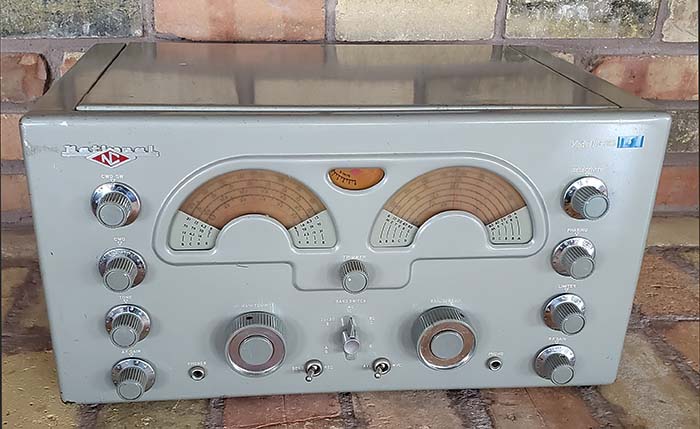
NC-173 SN: 173 2821
ca: 1948 "as purchased
condition" |
NC-173
SN: 173 2821 Purchase - I
saw this NC-173 on the "for sale to locals or
walk-ins" shelves in the front lobby of Ham & Hi-Fi
several months ago (Oct-2023.) The gear on the shelves
can't be sold on eBay for a variety of reasons, so the
gear is for sale
to walk-in locals,...if they're interested. I noticed (in October
2023)
that the receiver looked in
pretty good shape,...for a NC-173 anyway. The blue Dymo-label
in the upper right corner was a "turn-off" so I didn't
even look at the receiver any further and didn't ask anything about
it at that time.
About four months later and I was back at Ham
& Hi-Fi. The NC-173 was still setting there in the front
lobby along with a lot of other forlorn vintage
receivers and transmitters. Since nobody else was
interested in the NC-173, I bought it for a bargain
price of $30 on Feb 14, 2024.
NOTE: On
March 27, I was back at H&HF. ALL of the forlorn ham
gear in the front lobby was gone! This type of equipment
is kept available for quite a while giving locals a
chance to come in and purchase something at a very
reasonable price. However, after several months with no
interest, this type of equipment is sold for scrap.
|
|
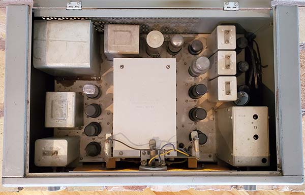
NC-173 Top of Chassis
before cleaning |
Preliminary
Physical Inspection
- A quick look "under the lid" and I could
see that the power transformer was original but there
was a little bit of black potting wax that had leaked
out. This indicates that the power transformer had
gotten hot but whether that did any serious damage will
have to be determined on the bench (I have an
original NC-173 spare power transformer if needed.)
The chassis was dusty but that easily brushed off with a
paint brush. That means "no grease or oil deposits" and
there were no indications of vermin habitation and no
corrosion either. The chassis should clean up nicely.
The matte aluminum pieces looked in excellent condition.
I didn't see any modifications on top of the chassis.
The AC power cord was hanging by only a couple of
strands of wire. The tuning and band spread dials were somewhat
darkened, but I've seen worse. The dial cover plastic was
extremely dirty and it was difficult to actually see the
dials very well. The S-meter looked pretty good without much
darkening. The tuning knobs do operate the pinch-wheels
and turn the dials but the operation is very stiff and
very
noisy and doesn't have the smooth feel that it should.
The BFO knob and shaft are loose and things are
rattling-around in the BFO can. The knobs all look
in excellent condition. The cabinet is in very good
shape. It needs some "touch-up" here and there but
nothing serious. The blue dymo-label is small and has
the number "6" on it. These are easy to remove using a
heat gun but it depends on how long the dymo-label was
stuck there as to whether a "dymo-label shadow" will be
evident after
the dymo-label is removed (heat gun allowed easy
removal of the dymo-label and, luckily, no shadow was
visible at all.)
Under
Chassis Inspection - Despite looking like
the power transformer "burned up" and leaked out some of
the black potting wax, it tested okay. I ran the
transformer with the rectifier tube pulled but all other
tubes and lamps installed and measured the voltages at
about 5vac, 6.3vac and 320-0-320vac and that seems "as
expected." I let the transformer run for
about ten minutes. The transformer remained cold, so
it's probably okay to use (although the HV-AC had no
load during this test.) I'll have to see how the
black wax cleans up. It's a mess under the chassis. All
of the original paper dielectric
capacitors and original electrolytic capacitors are still installed and the resistors don't
look like there are any replacements although there are
a few additions as described next. |
| Modifications are
as follows:
Modification removals are shown in italics. 1. Panadaptor
- The RCA phono jack on the rear of the chassis is for
connecting the receiver's IF to a panadaptor input.
Coaxial cable has been run from the RCA phono jack to
the 1st IF amplifier tube. A tie strip was added and an
RC installed to couple the IF to the panadaptor via the
RCA phono jack. Non-invasive because of where the RCA
phono jack was installed is where the hole is to allow
extraction of the band switch shaft (if necessary) so that hole
was original. Coaxial cable easily visible in photo. This
was an easy to remove mod. The tie point had been
mounted using an existing stud and nut, so easy removal.
No problems removing the RCA jack.
2. 5AR4 installed for
5Y3 - Pin-outs are compatible. Results in somewhat higher B+ since the
5AR4/GZ34 has a very low voltage drop where as the 5Y3 rectifier
is a somewhat higher voltage drop. Non-invasive.
Increasing B+ levels changes how some voltage dividers
operate and can cause things to run hotter than design
level. Add to that the increased AC line voltage we have
today and this ends up not being a good idea,...I'll
install a 5Y3GT tube.
3. B+ and B- Pin Jacks - The black pin jack is
connected to directly to B+ and the red pin jack is
connected to B- located on pin 4 on the Battery Socket.
Two tightly twisted wires are used for each connection (can
be seen in photo.) Unknown reason.
Except for the two pin jack mounting holes, non-invasive.
The twisted wires were wrapped around and through the
terminals involved which required cutting the wire at
the wrap in order to remove without damaging the
terminal. I had matte-silver metal hole plugs
for the pin jack holes. 4.
Tone Control Repurposed
- The 500K Tone Control is disconnected from the RC Tone
circuit and has two wires (as a 500K rheostat) that are routed though a
shield across the chassis to connect one wire to an
unused pin on the detector tube socket used for +150vdc BFO
plate voltage. The other wire connects to a 220K RF
amplifier tube screen load resistor. This has the RF
screen load R variable from 720K down to 220K apparently
to vary the screen voltage level on the RF amplifier
tube. Supplemental RF
gain control? Original wire and C for Tone control are
still present so this is basically non-invasive.
Cut the wires and removed the shield which had wraps of
soldered TC that used the RF box screws for
mounting. The original
Tone wire ends were reconditioned. The Tone control
mounting had to be
rotated CCW about 30º to have the original wires
routed correctly. Soldered original wires to complete
the Tone control. I removed the wires from the Detector
side, then the 220K was soldered back to pin 6 of the
Detector tube and the BFO coupling C was left
unconnected. It's the wrong value at 50pf which is five
times the original 10pf. Increasing the BFO
coupling cap value was a common mod to increase BFO injection
for easier SSB demodulation. Probably why the RF amp
screen voltage was changed to adjustable to allow
setting the
ratio of RF signal level to BFO injection for better SSB
demodulation. |
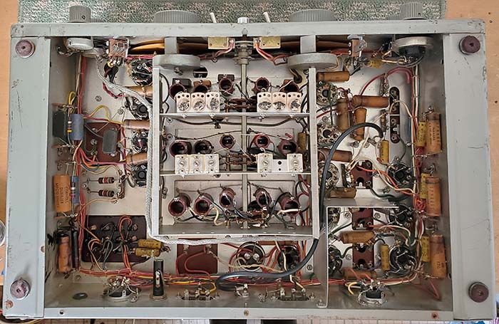
NC-173
Under the chassis with Mods
Before any
restoration, shows the mods described still installed.
The coaxial cable for the panadaptor mod is easy to
spot,...so is the shielded wire cable for the Tone
control repurposing. Note the twisted wire going to the
filter choke,...this is for the B+, B- pin jacks mod.
Note that the power transformer and components in the
lower left corner have a lot of black wax residue from overheating.
The two molded bakelite capacitors are .005uf 600vdc.
All of the .01uf 600vdc capacitors are Gudeman's Company
brand (never heard of 'em,...WWII surplus probably.) The remaining
capacitors are all Sprague brand (.1uf 400vdc and .05uf
600vdc.) |
|
Paper-dielectric Cap Count - There are .1uf
(11,) .01uf (10,) .05uf (5) and .005uf (2) paper
dielectric capacitors used in the NC-173. All total
there are
28 paper-dielectric capacitors. The two .005uf
capacitors are molded black bakelite rectangular style
(WWII surplus.) All electrolytic
capacitors are original and present. All waxed
paper-dielectric capacitors are original and present.
Removing the Chassis from
Cabinet - Feb 18, 2024 - I've noticed
that this procedure isn't in any of manuals for the
NC-173, 183 or 183D receivers. The dials on the 173/183
can be damaged if the chassis is removed from the
cabinet carelessly. Start by removing the bottom cover.
Next, remove the back of the cabinet. This will also
remove the lid which is attached to the back panel. Now,
looking from the back of the receiver the two dial
guides are easily visible. Remove the two dial guides
(these aren't used on the 183D.) Next, turn the receiver on
its side and remove the four felt-cup feet. Return the
receiver to the bottom-down position and the rear of the
chassis facing you. Notice how the chassis side flanges
have to slide through the cabinet side and bottom
flanges. Carefully position the chassis so the side
flanges will clear the cabinet flanges and pass through
the openings. This will allow the chassis to slide out
of the cabinet easily.
|
| BFO Problem
- The BFO frequency adjusting capacitor shaft was loose
and several things seemed to be rattling around inside
the BFO can. Three wires are all that connect the BFO
can into the circuit and then two nuts mount the
can to the chassis so removal for inspection is
pretty easy. Once dismounted the problem was
obvious, the ceramic mounting plate for the air
variable was broken in pieces. Several ceramic
pieces fell out when the can was removed from
the chassis. Replacement is just about the only
option. I salvaged the complete BFO assembly from the
"parts set" NC-183D.
It's an identical unit that even has the same
part number stamped on the side. No problems
with the installation of the NC-183D BFO into
the NC-173. The only difference is the three
wires have a slightly smaller diameter because
of the insulation thickness. Otherwise,
identical. |
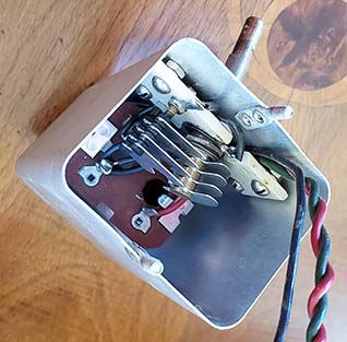
NC-173
Broken BFO Air Variable C |
|
| Other
Minor Mods Discovered - BFO Coupling Capacitor - The
non-original 50pf BFO coupling
capacitor was mentioned before. I used the ceramic BFO
coupling capacitor salvaged from the NC-183D parts set.
This cap was 20pf. It seems that the NC-173 used a 10pf,
the NC-183 used a 40pf and the NC-183D used a
20pf,...weird. Minor difference in original value since I've installed
the 20pf that will increase the BFO injection slightly.
Allen Set Screws
- When pulling the Main Dial and the Band Spread Dial, I
found that the set screws had been replaced in the Band
Spread dial with Allen-type set screws. All of the gears
also had Allen-type set screws. Only the Main Tuning
dial had the original type of set screws. I suppose
these Allen set screws were installed by a former owner
for some reason, but why didn't he do the Main Tuning
dial? >>> |
>>> When pulling the Band Spread dial,
loosening the Allen set screws using an Allen wrench was
difficult due to the over-tightened set screws that's
easy to do with this type of set screw. I checked the
NC-183D parts set and I have enough original type set
screws to replace all of the Allen set screws. I replaced all of the
Allen set screws with original set screws - Feb 20,
2024. I also noticed that the anti-backlash
springs were extended a lot. Only one gear tooth on the
split-gear is needed for ample backlash control.
Excessive anti-backlash will wear the pot-metal drive
gears quickly and it makes the tuning rough and "heavy
feeling." I adjusted the anti-backlash to one gear
tooth.
Audio Disconnected from Accessory Socket
- When dismounting the pinch wheel drive for the Band
Spread dial, I noticed a disconnected wire. I traced it
to the Accessory socket pin 6 which is the audio input
for either the NBFM adapter or the Select-O-Ject.
Unknown why it was disconnected but I reconnected it to
the PHONO jack as original. |
| Chassis Cleaning
- The chassis cad-plating is in excellent condition. I first
used WD-40 to remove any grease or oil. Then I used
Glass Plus to remove the WD-40 residue. The over-heated
power transformer must have spewed some black wax as vapor
towards the rear of the chassis. I had to use denatured
alcohol to remove the deposits. The tops of the power
transformer, the choke and the audio output transformer
were all spotty looking. I used a brass brush drawn only
in one direction followed by a wipe-down with WD-40.
This removed the spotty look. The brushed aluminum parts
were wiped with WD-40 and then with Glass Plus only
using dampened paper towels for application. This left
the aluminum clean and with a matte finish, as original.
Top of the Crystal Filter is plated steel so it had the
brass brush treatment. Generally, most of the cleaning
used WD-40 first, then Glass Plus and, if necessary,
denatured alcohol.
Cleaning the Black Wax Deposits - This
required denatured alcohol and acid brushes. Really
thick wax had to be scraped off first using various tools. The
terminals had to be cleaned with a very small steel
brush and denatured alcohol. The wires were flushed and
wiped multiple times to remove the wax. Alcohol-soaked
Q-tips were also used. A very messy job. This wasn't
that much black wax, probably about a teaspoon total. But,
when hot it spreads everywhere. This transformer appears to have gotten hot
but not to the point were it vaporized much of the wax, it looks
like most of it just flowed out of the seams a bit.
NOTE:
Lacquer thinner would have probably worked faster but I
was doing this cleaning inside the house. Denatured
alcohol doesn't smell as much as lacquer thinner and
denatured alcohol doesn't have the MEKs that are
in lacquer thinner. NOTE
2:
I'm going to retest this power transformer again to
confirm that the HV winding output is correct and then let it run for
at least an hour to see if it gets hot at all. 115vac
input on the primary resulted in 320vac on the secondary
to chassis (voltage as shown in the manual,) transformer cold to touch after an hour - no
loading, so no internal problems (2-21-2024.) |
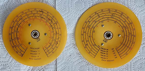
Dial
Cleaning
- I cleaned the NC-173 dials using the same method as
described in the NC-183
write-up. They turned out magnificent with very little
darkening of the plastic. The red is still vibrant and
the contrast after cleaning makes the dials look almost
new. For comparison, look at how darkened the dials
shown in the NC-183 write-up are. |
| Capacitor Restuffing
- With this NC-173 having all of its original waxed
cardboard shell capacitors, I decided to restuff the
original shells with polyfilms. After all of the effort
I've put into installing original set screws, de-mod'ing the receiver to
original, replacing the destroyed BFO with an original
exact replacement I think that I better save the under
chassis originality as much as possible (I know,...OCD.) The receiver chassis is just in beautiful
condition having cleaned up surprisingly well. The dials
have cleaned up quite well and are impressive. So, it
will take about a week longer to do the capacitor restuffing job.
The first step is to make a detailed drawing that
shows the location, the connections and the orientation
of each capacitor. I actually made two drawings to
divide the chassis in half so the capacitor connections can be
shown in detail. I also photographed at 12mp a detailed
photograph also for reference (it can be enlarged to
"mega size" on the
computer.) >>> |
>>> After the drawings are complete, then all
of the capacitors can be removed. It's much easier to
melt-out all of the capacitors at one time and end up
with just the shells to work with. I use a heat gun to melt out the
old capacitor. Then the shells are wiped with a paper
towel while hot to remove all dirt and excess wax. This
job can be done outside since it's sort of messy and
smells a bit.
With all of the shells ready, I just use masking tape
to build-up the diameter of the new polyfilm so it will
stay in place when put into the shell. The orientation I
use is if the nomenclature is right-side up, then the
outside foil is the lead to the left. It doesn't matter with polyfilms, but that's how I
install them anyway. Once the polyfilm is in the shell,
then the ends are filled with hot melt glue. When the
hot melt glue is cold then I color it using a brown
permanent marker so it looks more like the old wax. The
capacitor is then ready to install. I've found though
doing this many times, it's much easier to make up all
of the capacitors first. Then, when reinstalling the
rebuilt caps, I can concentrate on doing neat
professional job since I don't have to stop in the
middle of the job to rebuild more caps. Since I cut the
original caps out first, when doing the reinstallation,
I'll have to
remove the old leads, recondition the solder joint, wrap
the new rebuilt cap leads correctly and then solder.
This ends up with the entire chassis looking almost
original but having all new polyfilm capacitors and new
electrolytics. |
| More
Testing - Before pulling the original
capacitors all of the other components need to be
tested (2-21-2024.) Resistors
- All checked okay. One non-original 1 watt resistor
installed where original was 1/2 watt. IF screen load
R
probably burned because of leaky screen bypass cap so
they replaced the burned resistor with a greater
dissipation resistor and left the leaky cap in the circuit -
I've run into this quite often and there's just no
explanation for it. I replaced the 1 watt with a 1/2 watt
identical to the original and, of course, the
leaky capacitor-culprit is going to be replaced during the
"re-cap."
IF Transformers
- All checked out okay, including Crystal Filter and
Amplified AVC LC.
Potentiometers
- AF Gain pot needed to have two wires resoldered,
otherwise, no problem. The NL pot tested okay. The
Tone control tested okay. The RF gain showed open. I
unsoldered this potentiometer with the AC switch on
the back so I could disassemble it. The AC switch
has to be removed before the pot back cover can be
taken off. The entire wire-wound part was okay. I shot a little bit of DeOxit where the
arm brass contact rotates on a brass contact to
connect to the terminal. That seemed to get the pot
working again. Reassembled the RF gain pot with the
AC switch and reinstalled after reconditioning the
wire ends before reconnecting and soldering. Capacitor
Removal - Feb 21, 2024 - The location
drawings were made and all component testing that
can be performed without power was completed. I
clipped out the original capacitors making sure to
leave a stub for positive location identification
for the proper installation of the rebuilt caps.
Caps were sorted to eleven .1uf, ten .01uf, five
.05uf and two .005uf, 28 capacitors total. I also
pulled from stock the needed polyfilm capacitors.
Next, the old capacitors need to be melted out of
their shells,...an outside job,...tomorrow. |
Feb 22, 2024
- The .005uf capacitors are bakelite molded types so
I found two Aerovox small diameter shells to use for
the replacements. I melted all of the old capacitors
out of their shells. To do 28 capacitor shells took
a little over one hour. The .1uf 400vdc and the
.05uf 600vdc caps were all Sprague types which are
difficult to melt out because they used sealing wax
as an end-cap and this takes longer to melt and
doesn't stay liquid very long at all. Extra cleaning is
required to remove the residual sealing wax from the
shell. All of the .01uf 600vdc capacitors were Gudeman's-types. These were easy because the
end-caps were just bee's wax. The unusual look for
the Gudeman's are the shells are a mildly bright
yellow color (they'll stand out.) The next step is to
"stuff" the shells with the correct polyfilm caps.
Masking tape is wrapped around the polyfilm so that
it fits snuggly in the capacitor shell. I verify the
the correct value polyflim is being installed in the
matching capacitor shell and that the orientation is
correct. The .005uf capacitors were installed in
Aerovox shells that were small but were for .01uf
600vdc. I had to cut the shell to have it be the
correct size for .005uf 600vdc and then the ".01uf"
was changed to .005uf. All of the replica capacitors
are now ready to fill with hot melt
glue,...tomorrow.
Feb
23, 2024 - Hot Melt Glue - Before
proceeding with the hot melt glue, I tested all of
the capacitors with a Digital C Tester to verify
that I had the correct value cap in the correct
value shell. All 28 capacitors tested as correct.
The hot melt glue is injected to fill one end only
of each cap. By the time I get the 28th cap
end-filled, then the first ones are cool and I can
start over and fill the other side. I have a stand
that can hold up to 30 capacitors allowing them to set vertically as the hot
melt glue cools. The glue will contract as it cools
so most of the time I fill the end so the glue is a
convex "dome" that, by the time it cools, will be
more or less flat. If the glue fill is left flat,
then when it cools, the fill will be concave or "dished in" and
won't look right. Once all of the caps are filled on
both ends they're left to fully cool. Filling all 28
capacitors took about 45 minutes. When cool, then
the glue is colored brown using a permanent marker. |
| Installing the
Rebuilt Capacitors - Once all of the
replica capacitors are completed then they can be
reinstalled into the receiver. I was only going to
install just the .05uf rebuilt caps since there are
only five of those. As soon as I got "into it" I
found I had already installed eleven of the rebuilt
caps. I have to recondition the original solder
joints to remove the old capacitor lead ends. I use
a 125W Weller soldering gun for this part. The
soldering gun applies a lot of heat quickly and that
means that less time is required to remove the lead
and wick the solder. Less time means less heat
damage even though the solder gun is actually
hotter. I use the 25W Weller solder station for
resoldering unless it's a large terminal joint with
lots of wire connections that requires a good but
fast solder
"flow." Anyway, if one is careful, the 125W
soldering gun is safe to use. Seventeen rebuilt
capacitors remain to be installed. |
Feb 24,
2024 - More capacitors - Installed
fourteen rebuilt capacitors. Three left. Twice, I broke
the riveted solder lug while removing the old leads.
These are a lot more fragile than they look although the
problem might just be on this receiver. I did this same
type of work using the same equipment on the NC-183 and
never broke one of the chassis soldering lugs. For the two
lugs
I broke on the NC-173, I used adjacent grounding connections. |
|
Feb 25, 2024 - Yet Even
More Capacitors - All that was left was
to install the AC line bypass capacitors. While
accomplishing that I also used the original AC power
cord, reconditioned the ends and installed the cord. The
.005uf 6V6 plate capacitor was also installed. Since the
ripple filter capacitor across the filter choke did
require installation of one lead going to the 10uf-10uf
multi-section filter cap that still needed to be
rebuilt, I only connected one lead of this .1uf
capacitor that goes to the 5Y3 rectifier output (pins 1
and 8 tied together.) That completed the reinstallation
of the rebuilt capacitors.
Cathode and Bias
Electrolytic Capacitors - I rebuilt the
three 25uf electrolytic capacitors. I used a razor blade
to split open the "rolled end" shell. I wrapped the new
electrolytic in blue masking tape to get it secure in
the shell. I used two wraps of scrap wire twisted to
hold the shell tightly together at the slice. I then
filled the shell with hot melt glue. Let it cool and
then do the
other side. The hot melt glue holds the slice together
and the finished rebuilt electrolytic looks original,
unless you look at the ends. But, when they're installed
you can't see the ends very well anyway. Also, I made
sure the slice was facing down towards the chassis.
Feb 26, 2024 -
Rebuilding the Multi-section Filter Capacitor
- These are always a headache to do but if you don't want new
modern-looking filter capacitors under the chassis then
installing the new capacitors inside the original "can"
is what needs to be accomplished. The can has to be
bifurcated to remove the old capacitors. I use a hack
saw BUT, before sawing, I carefully scribe two parallel lines spaced
.125" apart around the can. Then one vertical line is
scribed through the two parallel lines. The two parallel lines
are guides that are used while sawing the can and allow you to keep
the sawing between the lines. After the can is apart and
the old capacitors removed (it's not necessary to
remove all of the black wax, just what's in the base
part and about 1" up from the cut in the top piece.
Aerovox usually didn't fill these metal cans very full
of the black wax anyway so removal of the old capacitor
is easy and very little of the black wax needs to be
removed.)
A file can be used to
dress down the saw marks while keeping the parallel
scribe lines visible. This allows a perfect fitting of
the two pieces. The vertical scribe line also helps in exactly
orienting how
the two pieces should fit together. Normally, the
original capacitors weren't soldered to the terminals
inside (they're usually crimped because the capacitor
foil was aluminum.) It's necessary to drill three small holes to
allow the new electrolytic capacitor leads to exit out next to the
terminals and then wrap around the terminals for
soldering. Once this is done, then the can is
epoxy-glued back together. I use heavy paper to make a
small cylinder that fits inside the can at the joint.
The paper is coated with epoxy on the side next to the
inside of the can pieces and then the two can pieces are "fit"
together. The excess epoxy can be wiped off the can
joint with
a paper towel. I then install one wrap of masking tape around the can
"over the top and around the bottom" to
keep the joint together tightly. After the epoxy cures,
I remove the tape and
then the seam can be painted with silver paint to help
hide the joint. The new rebuilt filter capacitor can
then be reinstalled. Time required to rebuild the
multi-section is about 1 hour.
With the multi-section placed in it's clamp but not
tightened yet, the can was rotated until the
terminals were inline with my drawing, then the clamp
was tightened. This assured that
the original hook-up wires would be long enough and
oriented correctly. I also had to connect the other end
of the .1uf ripple-filter capacitor. This completed the
capacitor rebuild and reinstallation part of the
project. |
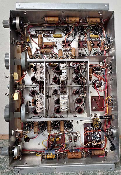
NC-173 Under the chassis
after cap rebuild |
|
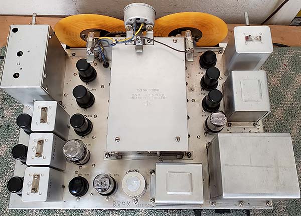
NC-173 Top of Chassis
after
cleaning - it turned out really nice. Notice how the BFO
from the NC-183D looks exactly like
the original "broken" NC-173 BFO (same part
no.) |
Feb 27,
2024 - Dials, Gears, Pinch-wheels, Tubes and Preliminary
Testing - I double-checked that the two
split-gears were set to just one gear tooth of
anti-backlash and then I installed the two dials. To
synchronize the
dials to the Tuning and Band Spread capacitors, note
that the dials each have rotational stops. The tuning capacitor and
band spread capacitor have to be set to full mesh and
then the dials are set to the low end of the dial scale
against the rotational stop and then the set screws
tightened. This is the mechanical preset for the dials
that will allow for accurate alignment and tracking.
When the chassis is installed in the cabinet then the
dial fiducial indexes are adjusted for an accurate dial
indication before alignment is performed. Next, the
two pinch-wheel drives were cleaned and, when reassembled,
new damping grease was used for the main shaft only in
the main bearing. The pinch-wheel drive has to be
assembled in the receiver chassis to make sure that the
interface of the dial into the pinch-wheel is correct.
Too little engagement and the dial will slip. Too much
engagement and the dial tuning feels very heavy and
rough. This setting is important so the receiver tuning
is light-feeling but doesn't slip.
All of the tubes were tested. I needed to replace the
5AR4 with a 5Y3, I used a NOS 5Y3GT. All three of the
6SG7 tubes tested far below minimum acceptable. Two of the
6SG7 tubes barely moved the meter on the TV-7. The 6AC7
tube tested with high leakage (tests as a short.) The two 6SJ7
tubes tested very good. The 6V6GT tested very good. The
6SA7 tube tested good but I already had a NOS 6AS7 tube to
install. The 6J5 tube tested very
good. I found several 6SG7 tubes in the shop storage but none
were NOS, so I had to select the three that tested best
to install. I installed a NOS 6AC7 tube and a NOS 6SA7
tube. The 0D3 tested good. I ended up replacing seven of
the thirteen tubes. I cleaned the rotor contacts
on the tuning and band spread capacitor with DeOxit and
a small brush. I gave the band switch the same
treatment. I installed the S-meter. I installed the
tuning capacitor cover. I used test leads to connect an
8Z ohm speaker and a ten foot test antenna. I connected
a DC voltmeter to the B+ to monitor the actual B+ with
the complete load on the power supply. |
| Testing
the NC-173 - Feb 27, 2024 - The receiver was ramped up
to 115vac input using the Powerstat and the B+ read about +220vdc at the filter
capacitor, which is about right. I switched to the AM-BC
band. Nothing heard. I turned on the BFO and it was
working fine. I switched the REC-STDBY and that
momentarily got some signal. I sprayed some DeOxit down
the barrel which quieted down the switching. The tuning
capacitor seemed to be a problem so I removed the cover
to check but saw nothing unusual. When I powered up the
receiver again, this time it came on strong with signals
up and down the AM-BC band. The audio quality sounded
really good,...much better than I was expecting,...and
that's using a test speaker (Radio Shack 8" 8Z in a
small wooden box.) I think I'll remove all of the tubes
and use DeOxit to clean the sockets (I didn't do that
and I should have.) Cleaned the tube sockets. The
intermittent problem was still present. I input a 455kc
modulated signal to the Mixer grid and the signal came
through strong, so the problem was in the front end. I
replaced the front end tubes one by one. When I replaced the Mixer
tube, everything began to work correctly. The Mixer was
a NOS 6SA7 so, even though it tested good in the TV-7,
when installed in the
receiver it acted up (a tube tester ISN'T the final
word on tube functionability - correct operation in the
circuit is what's required.) I replaced the erratic
6SA7 with the original tested-good 6SA7.
Installing the
Pinch-wheel Drive Assemblies - Cleaned
and installed the pinch-wheel drives. I used fibrous
sodium based grease that has good damping
characteristics. The Band Spread installed quite easily
with no slipping and smooth operation. The Main Tuning
required several adjustments to eliminate slipping but
I'm going to have to do some more adjusting because
although there's no slipping, the tuning feels a little
rough, not bad but noticeable. Slight lift on the tuning
condenser frame should do the trick. The slight lift is
accomplished by loosening the condenser nut on top of
the chassis which will also loosen the nut under the
chassis. Then the under the chassis nut can be turned
out about one full turn. Then the top chassis nut can be
tightened. This tightening will "pull" the condenser
"up" slightly and reduce the engagement of the dial in
the pinch-wheel. The end result is the adjustment can be
made without disassembling the pinch-wheel drive.
|
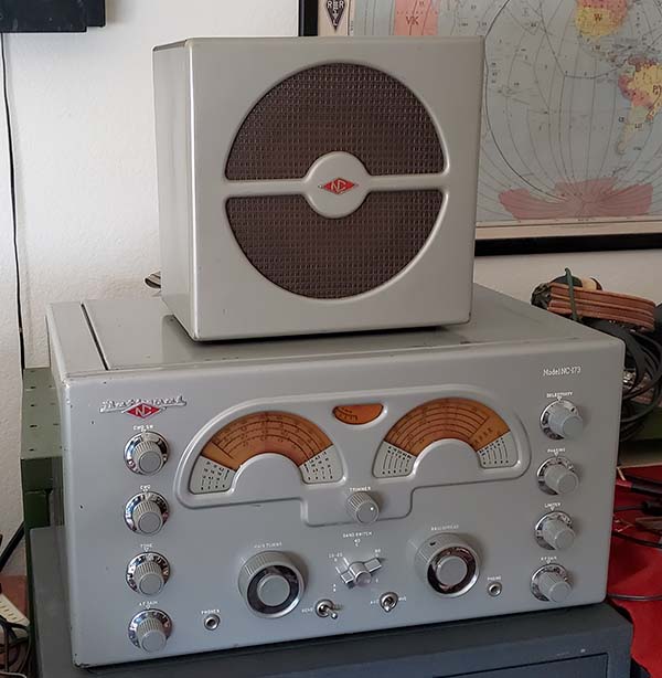
NC-173 SN: 173 2621
and NC-173TS Loudspeaker
After restoration,
original and cleaned dials but not illuminated |
|
Installing the Cabinet - Feb 28, 2024 -
Removed the plastic dial cover from the cabinet and
thoroughly cleaned it using Glass Plus. The NC-173
doesn't use the aluminum spacers like the NC-183. This
is due to the embossed area being just around the dials
allows mounting the plastic beyond the embossed area so
the dial cover is at the proper height for the dial
openings without the spacers. I gave the cabinet a Glass
Plus washing but it wasn't really too dirty. There were
some residual tape pieces that had to be removed with
denatured alcohol. On the inside of the cabinet there
was a small deposit of transformer black wax. I scraped
most of it off and the remainder was easily removed with
WD-40. The inside of the cabinet was also washed with
Glass Plus. I remounted the dial cover after the cabinet
cleaning. Next the dial fiducial index pointers had to
be mounted. These have to have the correct angle so that
when mounted they are up against the backside of the
dial cover (gives the necessary clearance for the
dials.) Now the chassis can be installed from the rear
of the cabinet. Be sure to guide the chassis side
flanges through the opening in the lower corners of the
rear cabinet flanges. Once the cabinet is properly in
place the bottom felt cup-feet can be installed. |
Cabinet and Chassis
Alignments - I found that the Main Tuning
dial was way too close to the front and needed to be
placed back on its shaft about .125" for good clearance.
The indexes were both bent back slightly and needed to
be removed and adjusted. Of course, this means removing
the chassis out of the cabinet. But, once the index
angle was correct, then both indexes were up against the
plastic when tightened. With the chassis again
installed, then the dial guides were installed. These
will keep the dials from rubbing the indexes. I tested
the tuning for both Main Tuning and Band Spread and both
worked fine, didn't rub against the indexes and looked
like both were the same distance behind the dial cover.
Next, the indexes are again adjusted. The dials are set
to the lowest frequency end until the dial hub pin hits
the gear stop. Then the index mounting nuts are loosened
and the index positioned to align with the minimum scale
indication which is "0" on the logging scale. Then the
mounting nuts are tightened. This assumes that you've
already synchronized the dials to be correct with the
Tuning and Band Spread condensers at full mesh. |
|
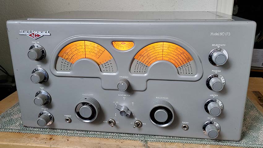
NC-173 SN: 173 2821
Rebuild Finished. I haven't done any
"touch up" painting on the cabinet on this receiver. It
cleaned up very well and, while it has a few nicks and
little scratches, it's a pretty good example of
acceptable cosmetic condition.
But, in the future I'm sure I'll do the cabinet paint "touch up" and
that should further improve the overall cosmetics of the
receiver. The smaller size and reduced weight of the
NC-173 results in a very convenient to use station
receiver, especially on 80M AM, where its performance is
superb. |
Installing the Back Cover and Lid Assembly - Feb 29,
2024 - The top lid and back cover were
cleaned with Glass Plus first. There were a few
tube-heat discoloration spots under the lid but these washed
off with either Glass Plus or denatured alcohol if
necessary. The back cover was mounted
using the original philip's head sheet metal screws.
After the back cover was installed then it was
necessary to loosen the lid hinge screws to position the
lid so the it sets flat in the top tray of the cabinet.
Tightening the hinge screws might pull the lid one way
or the other so this is a sort of trial and error
adjustment. Once the back and lid are installed then the
bottom cover can be installed to see how it fits. I had
to clean the inside of the bottom cover since a little
of the transformer black wax had dripped there. I
scraped most of it off with a razor blade and removed what
was left with WD-40 and Glass Plus. There are two paper
tags on the bottom cover. The Hazeltine patent label had
a date of 12-46 which was interesting. The incorrect
screws were installed to mount the bottom so I used the
correct type when installing the bottom cover. This
pretty much completed the NC-173 rebuild. Now it's time
for the "shake down" to see how it's going to perform.
Shake Down Results -
March 1, 2024
- Tuned around 20M about 1400hrs PST. Fairly
active, mostly North American stations. Tried to find
Trenton Military on 15.035mc USB but couldn't hear them
if they were transmitting. Tried the Chinese Mainland
Maritime beacons and heard XSG 16.954mc with a strong
signal steady signal (about RST 579.) I decided to tune
even higher and give 15M a try, heard one SSB net mostly
W5s. Went up to 10M and was surprised to hear quite a
bit of activity, one JA station from Japan working
stateside stations. Tried 6M and heard three unmodulated signals
that weren't identifiable (beacons?) Stations on
20M CW were steady with good solid tone, no instability.
Didn't hear any CW on 10M or 15M. XSG also had a solid
steady CW note. RF tracking is excellent, I don't
think any alignment of the LO is necessary or even
desirable since it's almost perfect. A total surprise
since I had the dials off. Performance is very good and
I'll use it as a station receiver soon.
UPDATE:
The NC-173 was set-up with the W6MIT "1625 Rig" - a 75
watt output homebrew transmitter. Antenna was the
Collinear Array. Sea Trials began on March 17, 2024. An
excellent receiver, no problems experienced. The one
issue is the S-meter action on 80M when using a very large
array antenna. Most ham AM signals "peg" the S-meter.
There are two ways to compensate, the first would be to
reduce the RF gain so the signal strength is at a level
that's within the S-meter scaling but this method is
changing the front end sensitivity. Second, is to reduce
the signal level using the TRIMMER, which is what I
prefer to do since that is reducing the signal level at
the Antenna input. The NC-173 has accurate calibration and
its audio reproduction is superb. An excellent receiver
on 80M AM. |
| Conclusion
- Introduced during that post-WWII time when most of
the communication receivers being produced were
either repackaging of pre-WWII designs (or actual WWII
designs,) the NC-173 and NC-183 receivers were designed
with a different end-user in mind, the SWL that might
also be a budding audiophile or maybe even a
discriminating radio
amateur. With a front-end design that was up-to-date
with the late-forties technology coupled with what was
then considered "powerhouse" audio, the NC-183 was a different
type of post-WWII receiver that could provide enjoyment for
several different types of users. The NC-173 was a "true
ham receiver." Maybe a little less sophisticated but still
it was a capable receiver in the right hands,...a radio
amateur. A few years later, with many changes in the ham
radio operational environment, the NC-183 underwent a major redesign to
become the ultimate example of the NC-173/183 receiver
family, the NC-183D. With
double-preselection, dual-conversion, triple IF
amplification and high fidelity audio built with
high-quality components in a robust chassis with
heavy-duty mechanics, the NC-183D has become the
"vintage receiver of choice" for the AM ham operator
that really wants to enjoy listening to that "AM sound"
and still be able to cope with all of the modern day ham
band reception issues. Luckily, finding a really good
condition NC-183D isn't too difficult. Many of the "D"
receivers seem to have endured time quite well and with
a proper rebuild and alignment they can still provide
top performance no matter what your particular radio
reception interests happen to be. But, if you want to
experience really superb audio reproduction, the
NC-183, with its wider IF passband, can provide tremendous
wide-range audio when rebuilt and aligned correctly and used with a
large, well-designed loudspeaker. Even the single-ended
audio of the NC-173 can sound great when the receiver is
rebuilt, aligned and used with a good quality loudspeaker. Any
one of the three models, the NC-183D, the NC-183 and the
NC-173 would be an excellent choice as a receiver for a
vintage ham station today. |
References
Hardcopy:1. Manuals for NC-183D, NC-183
and NC-173 - National manuals are always a little sparse
on information especially
when it comes to design intention and detailed circuit
descriptions. Just the basics are provided along with a parts list, schematic
and alignment instructions.
2.
1950, 1956 ARRL Handbook - National Co.,Inc. - period advertising
3. Communications Receivers 4th Edition, Ray Moore -
basic descriptions
4. QST magazine, issues March 1947, April 1947 and
December 1947 - introduction of NC-173 and NC-183. I
scanned original ads from either QST magazines or from
ARRL HBs for this article for the best quality of
reproduction.
Online:
1. BAMA Edebris - references to other data on all
three receivers. The NC-173 schematic jpeg on BAMA (the
one that isn't the cleaned-up original)
contains many errors. Some values shown are incorrect,
the Accessory socket wiring is left out completely and
the Battery Power Socket is drawn incorrectly (the
pin outs shown for remote standby would actually short
the rectifier output to chassis ground,...oops.) 2. National Co.,
Inc. - period advertisements for NC-173, NC-183 and NC-183D
are easily found on the Internet.
3. National Radio Reflector - Google e-mail group for
National Co, Inc. enthusiasts. Search "mailman.qth.net"
to see the list of groups and to find out details on
becoming a member of the National Radio Reflector group.
Thanks to those members that have sent their serial
numbers to me, I've added them to the NC-173, NC-183 and
NC-183D serial number log. |
|