|
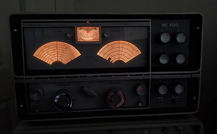
The receiver does have to be mounted in
the cabinet to achieve the best stability. How NC-400
receivers were ever used rack-mounted is a mystery (probably
with side rails.) The cabinet
frame and
screw-mounting provides the support the flexible chassis
requires. The NC-400 can pull in weak signals quite well, especially after a
careful alignment. It probably will take a bit of listening and working
with
the receiver to eventually get the most out of it. The NC-400 can be a
sensitive receiver. It can be selective enough when necessary
and also can be set-up for a broad IF passband to enjoy some of
the quality SW BC stations - are there any left? Ownership and
actually operating the NC-400 for a while will go a
long way toward one's overall appreciation of the NC-400 and
certainly its electronic performance is at the forefront of that
appreciation. The audio quality is a pleasant surprise considering
it's just a single-ended 6AQ5 that's producing the very natural sounding
reproduction. However, the Tone switch is next to useless since it just
reduces the high audio frequencies slightly by switching in a
bypass capacitor (for $895, one
would think National would have installed a true adjustable Tone
control.) For the best audio reproduction, use a good
quality, moderately large diameter speaker, 8" to 12" is
sufficient, installed in a decent housing and the NC-400 audio
will sound great. Finding the matching loudspeaker, the NTS-2,
is difficult. I run my NC-400 using the balanced 600Z output to
a good quality eight-inch speaker in a large wooden cabinet with a 600Z to
8Z matching transformer. The sound quality is pleasant. There
already is a 22 ohm load resistor on the 3.2Z output so nothing
has to be connected there when using the 600Z line. Also, the
phone jack is on the 3.2Z output but since there's the 22 ohm
R load any impedance phones can be used.
That being said, the NC-400 has many, MANY quirks.
First, the good quirks,...the
multiple IF selections will take getting used to. You can
receive CW and SSB signals (even AM signals) several different ways with
combinations of the Mode switch and the IF Selectivity switch.
Once it's determined that SB1 is LSB and SB2 is USB, then
selecting the proper sideband isn't difficult but a slight
adjustment of the BFO will be necessary on either LSB or USB for best
demodulation of the SSB signal (an easy way to remember USB
versus LSB is that SB2 is the "higher number" and is the "upper
sideband.") You can use SB1 or SB2 in the AM
mode for an interesting type of AM reception. For exalted
carrier AM, you have to switch to CW and adjust the BFO for
zero-beat (no AVC in this position.)
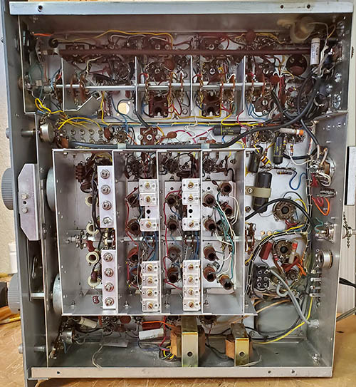
It's important to remember that when you're in B, M or S
bandwidths, you're using a different IF section in the receiver
with only six tuned circuits. But, you can run the AM signal
through the 14 tuned IF circuits by using SB1 or SB2 for a fixed
3.5kc bandwidth. Or, you can run the AM signal through VS and
have 10 tuned IF circuits and also use the Crystal Filter. CW
signals or SSB signals can also be run through the various IF
circuitry. There are many methods to try, which does seem to
backup National's advertising claim that the NC-400 was "the
most versatile receiver available."
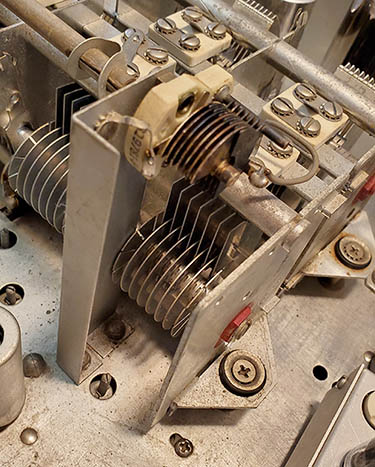
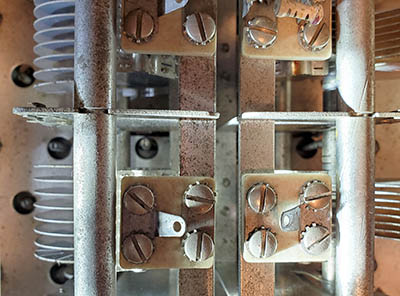
Now, the bad quirks,...the insolvable problems
are all mechanical in nature. Like the flexible chassis and
component mountings that cause frequency excursions whenever
certain adjustments are made. Or the vague frequency readout
that gets worse as the tuned frequency gets higher and higher.
When actually using the NC-400 "on the air" most vintage ham
gear operators will have a digital frequency counter set up to
read the transmitter frequency. The NC-400 can be "zero beat"
against the "tune" or "spot" function from the transmitter and
the receiver will be "on frequency." But, those crappy "band-in-use" indicators that stick and never seem to
point to the band you're actually on, or the "mega-torque" band
switch that causes shockwaves throughout the chassis as it's
operated and the cheap knobs that give the controls a flimsy feeling
are other irritations that you'll eventually have to accept. The sheer size of
the receiver and its 75+ pounds of bulk weight requires a
lot of bench real estate but that could be viewed as a "commanding
bench presence" and that might compensate for the lack of table
space. In many vintage amateur radio station installations the receivers aren't moved
around very often, either physically or even tuned frequency.
Sometimes many of the adjustments are only made once and then
left alone. So, perhaps most of the mechanical problems really
won't be that much of an issue (unless you have an OCD nature
and want everything to be "perfect!")
I have used my NC-400 connected to my 75M
collinear array antenna. This is a 240' center-fed
dipole with
108' open feed line to a 1KW Johnson Matchbox tuner that's operated
on 75M (two half-waves in-phase.) This is a
substantial antenna that does exhibit a little gain (~1.9db) and
does allow hearing very weak signals. But, the NC-400 noise
floor is pretty high with this antenna so for the best sounding
signals I'll reduce the RF gain from maximum until the S-meter
reading just begins to drop. At this point the signal is still
creating AVC voltage but the background noise is greatly
reduced. I think that SSB signals actually sound much better
with the RF gain reduced slightly in this manner. CW signals
will require reducing the RF gain somewhat since the AVC is turned off
by selecting CW but the CW signal is still routed through the
Product Detector. Also, you can listen to CW in the SSB position
and then have AVC, if desired. Strong AM signals, with using a
diode detector and a different IF section, can do
rather well with full RF gain but, with weaker AM signals, better results
(especially with QRN
present) will be with the RF gain slightly reduced. As mentioned
above, you can route AM, CW or SSB signals though any of the
various IF bandwidth or Mode options to experiment with what
works best for the receiving conditions.
For signals outside the 75M ham
band, the Matchbox allows "tuning" the antenna for a good match
anywhere from 3.5mc up to 25mc. I listen to 20M a lot since it's
a daytime DX band and I do most of my listening during the day. Listening to the Chinese CW Coastal
Beacons is pretty easy on 16.9mc in the later afternoon. Any of the SW
BC stations sound
pretty good but the best broadcast audio quality signals seem to be coming
out of China these days. The Chinese are producing powerful signals
with lots of modulation and a wide bandwidth (well, maybe not
Firedrake, but most other Chinese stations.) Radio Havana is strong
too but their
modulation is a little
rough sounding and their announcers are annoying to listen to.
So, despite the mechanical quirks, give your NC-400 a little time. Experiment with the many different
methods to demodulate signals. I think when
you get used to those "good" quirks and when (or if) you get used to its
unique appearance, the NC-400 can become a fine station
receiver,...one that isn't seen all that often and at least you didn't have to pay the 1959 $895 cost in
2023 dollars (9200 of 'em.) I can't really say that I've
followed my own advice though. I always find the performance of
the NC-400 lacking and I just can't wait to replace it with a
decent performing receiver.
|
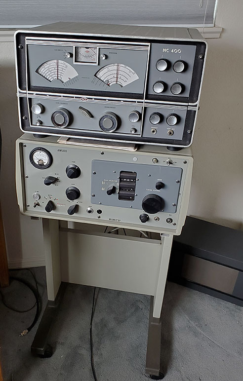
I had my NC-400 set up with the W6MIT homebrew
transmitter, shown in the photo above. Though W6MIT's transmitter
might be a little short on "good looks"
just the opposite is true of its incredible audio quality on AM. A
really stellar homebrew transmitter. At only 75 watts of carrier
power, I find that using the 75M collinear array antenna is a big help. Most of the
time, the "1625 Rig" with the collinear produces a good signal that is Q5 with most check-ins to
the Vintage Mil-Rad Net. And, the gain of the antenna also helps with the
received signals (gain is about 1.9db.) I have to admit though,...I've had this
particular set-up on two different occasions and neither time did using the
NC-400 result in a long-term relationship. I just couldn't wait to replace the
NC-400 with a decent performing receiver. |