Radio Boulevard
Western Historic Radio Museum
 

NATIONAL COMPANY, INC.


"MOVING COIL" COMMUNICATION RECEIVERS


Includes NC-100, NC-101X, NC-80X, NC-81X, NC-100A family,
 NC-200, NC-240CS, NC-240D
Dept of Commerce & CAA Airway Communication Receivers
Military Versions - RAO family, RBH, NC-100ASD, R-115, R-116

by: Henry Rogers WA7YBS-WHRM


     PART 1 - History of the Moving Coil Receivers, Details on production models 1936 to 1948, Airport Receivers, US Navy models, US Army models, USCG models.


     PART 2 - Serial Numbers & Log, Production Engineering Changes, Catacomb details, PW Gearbox, PW-D, Tubes, Power Transformer info, Speakers


     PART 3 - Restoration Write-ups: NC-200 Silver Anniversary, NC-100XA, NC-100ASD
 

     PART 4 - Restoration Write-ups: RCE Airport Receiver, NC-101X, NC-80X


PART 3

Restoration Write-ups

If you read the following restoration write-ups "one after the other," you'll find them somewhat repetitious, more or less covering the same steps over and over. My intent is,  if you're working on a particular model of Moving Coil receiver, you can check out my write-up on that same model (or a similar version) and read what sort of problems I encountered. Most of these write-ups were written while the rework progressed to illustrate the order in which the work was performed. I've also included my mistakes which might help restorers avoid those types of problems with their rebuilds. 


Restoration of the Silver Anniversary NC-200  sn: C-536

This project started out as a "return to original" condition because of a "hamster-job rework" performed by a former owner. I hadn't really decided whether to leave the receiver in good cosmetic condition doing duty as a "shelf-queen," or whether to do a complete "museum quality" restoration job so the receiver would also be a reliable performer. Curious temptation for a "quickie power-up test" resulted in finding a defective power transformer and this was the deciding factor to go ahead with the full restoration. Also covered in this write-up is how to replace the plastic dial cover with a new repro dial cover. This method can also be used on the NC-240D receivers.

I acquired this Silver Anniversary NC-200 and matching speaker as a trade that involved a restored BC-344-N receiver. The NC-200 receiver was mostly in very good, original condition as far as the cosmetics were concerned (although somewhat dirty.) The original can electrolytic capacitors had be rebuilt by a former owner in a most unusual way using orange plastic pill bottles on the interior holding the new capacitors. The tops of both cans were missing and the metal back-covers from potentiometers were installed as tops instead. Under the chassis, three capacitors had been replace with modern "orange drops." Everything else was still original. The receiver had never been "powered-up" by the former owner.

My initial goal was to just re-do the electrolytic capacitors to appear original, re-install original Sprague paper-wax capacitors where needed and to do a cleaning. I thought I'd just have the Silver Anniversary as a "shelf-queen" because,...who needed another restored "moving coil" receiver anyway?...,...right?

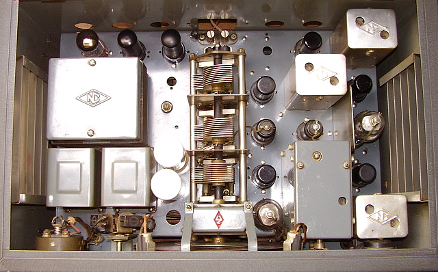
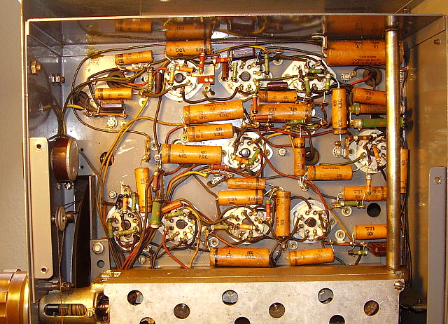
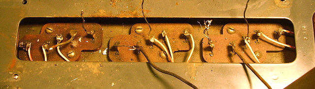
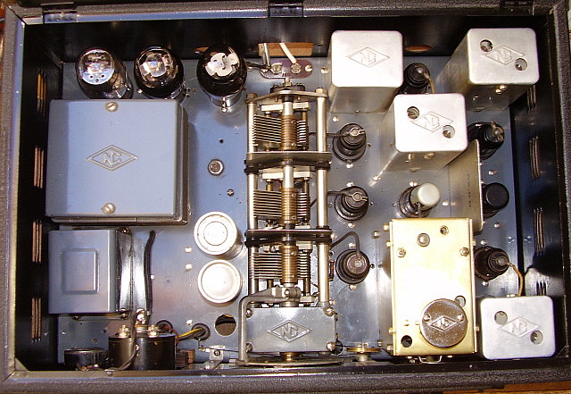
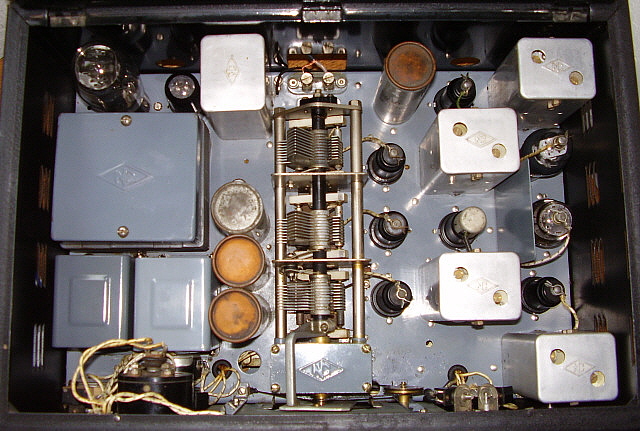
Rebuilding the Electrolytic Cans - This required removal of the plastic pill bottles and new electrolytic caps and accurately trimming the cut that had removed the tops. I then looked in the junk box for some defective can electrolytics (easy to find) and accurately cut the tops off of two of the cans. Since both the original cans and the new tops were the same outside diameter, as long as the cuts were accurately accomplished the seam joining the two pieces together should be minimal. I installed a dual 10uf 450wvdc in the can that originally was a dual 8uf and I installed a 40uf 300wvdc in the can that originally was a 40uf at 200wvdc. The new tops were then mounted using epoxy with a cardboard tube inside (to hold the epoxy.) The finished caps looked nearly perfect and, other than the new caps inside and the new tops, they were essentially the original cans for the receiver.


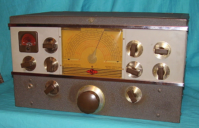
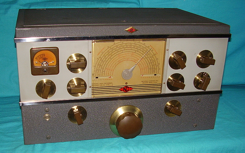
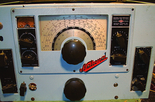
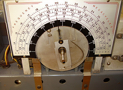
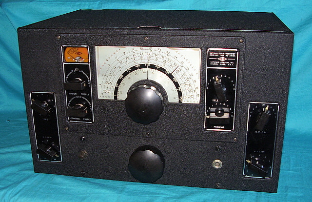
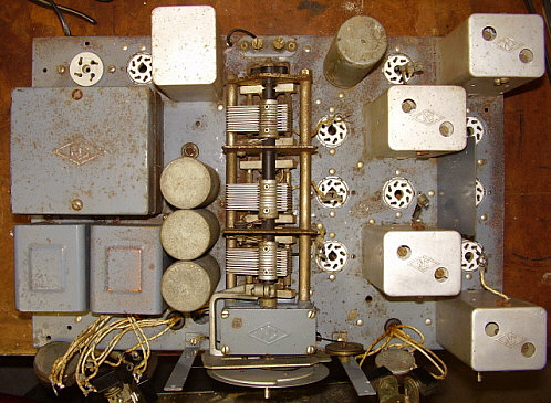
photo above: The Silver Anniversary NC-200 as received.  Dirty, no NC diamond and an ultra-dark S-meter scale.

Cleaning - The only way to really clean the chassis is to remove the cabinet. The bottom is mounted with several sheet metal screws, including two on each side of the cabinet that must be removed. Then the back and lid assembly is mounted using sheet metal screws. The knobs and control mounting nuts have to be removed to dismount the front and sides assembly. Four 10-32 machine screws  and nuts are used to also secure the front panel to the chassis which also must be removed. The front and sides assembly then pulls forward and up to dismount. The chassis is now easy to access for cleaning. Like many older receivers, this one had been somewhere exposed to greasy or oily dirt. WD-40 removes this kind of grime easily. You'll usually find this dirt is an excellent preservative and the chassis paint will clean up nicely. Once the grease is removed, I then clean the chassis with Glass Plus to remove the WD-40 residue. Don't scrub the aluminum shields as this will tend to polish them. They should be matte finish. Lightly clean with WD-40 followed by Glass Plus. Use a soft paint brush to lightly remove the dirt then dab dry. This will preserve the matte finish and clean the aluminum surface. Most pre-war National equipment will have acceptance markings on the IF cans that consists of orange grease pencil "OK" or maybe initials. These orange grease pencil markings shouldn't be removed during cleaning. Cleaning the Wrinkle Finish - Use Glass Plus and a soft brass brush (sometimes sold as brushes for suede shoes - they are kind of hard to find.) Spray a heavy coat of Glass Plus on the wrinkle surface and then use a circular motion with the brass brush for several minutes. Don't scrub hard but use gentle to moderate pressure in a circular motion to clean the dirt out of the convolutions of the wrinkle paint. The original wrinkle paint is very tough and can take this treatment. Wipe off the dirty Glass Plus with dry paper towels. You'll have some dirt and a little color showing on the paper towels. Do one more application. The paper towel should be pretty light on dirt and color this time. Move on the the next surface and use the same procedure. When all sides have been cleaned, let the wrinkle finish piece dry completely. Then apply 10W machine oil with a clean cotton cloth and rub into the wrinkle finish. You don't need a lot of oil since very little covers a fairly large area. Wipe off the excess with a clean, dry cloth. The oil works much better than Armor All and doesn't leave the surface feeling "slippery." Also, the oil provides a nice luster and doesn't have the "glossy shine" that Armor All has.


photo above: The NC-200 chassis after chassis cleaning, rebuilding the metal-can electrolytics and installing a replacement power transformer (using original cover and skirt though.) Note the brown S-meter case.

Cleaning Knobs and the Meter Case - Soak in warm soapy water for about 30 minutes. Scrub with a soft tooth brush to remove the dirt and then dry. Now polish each knob with Wenol's or Semichrome. The meter case can be cleaned with Glass Plus and then polished with Wenol's. With this receiver the S-meter scale was extremely dark from having a high-current lamp installed for illumination. I swapped scales from another National (Marion Electric) meter that was only slightly darkened. Originally, these scales were light yellow and the red nomenclature was bright and easy to read but UV light and high heat illumination darkens the plastic and fades the red printing.

Replace Power Cord - I just couldn't leave a Kawasaki power cord installed on this receiver. I didn't even know Kawasaki made electrical parts. I looked around in the junk pile to find a vintage radio that still had it's original power cord. I found an old junk broadcast radio that had its original power cord and molded plug (and that was still pliable.) Later, with the second power transformer installation, I used an original NC-101X power cord from a parts set. This power cord was in great condition with the original molded plug.

Repair NC Diamond - I was really lucky that the former owner had kept the Silver Anniversary NC diamond after it had become detached from its mount. To remove the mount required that the cabinet be apart (which it was, for cleaning.) I used a jeweler's file to clean the back of the NC diamond and the top of the screw mount. I then used high-tensile strength epoxy to "glue" the diamond to the mount. I think originally the diamond was soldered to the mount and then the cloisenne NC and the plating was done. I wasn't sure that the heat of a solder mounting wouldn't damage the cloisenne so I opt'd for the epoxy which worked fine.

Re-doing the Gold Tone - This finish was almost totally worn off from years of use. It wasn't an electroplating but rather was a gold tone lacquer that wasn't very durable. I initially thought the gold tone was smoker's residue but tobacco deposits are water soluble and this toned lacquer, of course, wasn't. My "tip off" to the true nature of the gold tone came when I removed the large brown bakelite tuning knob from its skirt. There, protected by the knob, was the original color finish - a light gold color (about the color of beer.) I was lucky to have a special yellow toning nitrocellulose lacquer that had been mixed for me several years ago for duplicating amber lacquer finishes. I had found that diluted a little, this lacquer also duplicated MFP coatings (without the smell.) I had also used this lacquer to duplicate the gold finish on HRO crystal filter boxes, so I knew this would work fine for the gold tone necessary for the Silver Anniversary. Mixed about 3 to 1 with thinner and lightly sprayed, the yellow lacquer duplicated the color found under the tuning knob exactly. I also shot all of the nomenclature plates since the two Crystal Filter plates still had their gold tone present indicating that all of these plates were also gold tone.

Functional Test Finds Bad Power Transformer - The Silver Anniversary NC-200 was reassembled and then photographed for this website. I thought that was going to be the extent of the work performed. I had asked the former owner if he had ever powered up the receiver. He said that he hadn't but that the fellow he got it from had said it worked. Hmmm. I couldn't resist temptation. Since I had the original matching speaker, I connected up everything and carefully applied AC power. I watched the 5Y3 rectifier tube to see if any blue glow would indicate a severe overload but everything looked fine. In about 25 seconds, receiver background noise came over the loudspeaker. I connected an antenna and signals were coming in strong. I tuned around on all bands and everything was working fairly well. After about ten minutes, I though I better feel the power transformer. It was very hot. I felt the chokes and they were still cold. Hmmm. This indicated that there wasn't a high current flow thru the chokes as would be the case with a high leakage capacitor load on the B+. I turned off the receiver. The next day, I pulled all the tubes along with the three lamps and again powered up the receiver. After about ten minutes the transformer was again hot and beginning to smell. A sure indication that the power transformer had a problem. The removal of the rectifier tube removes the entire HV winding and the 5vac winding from that load on the transformer. With the remaining tubes and the lamps removed (the 6.3vac load) there was "no load" on the transformer. I also checked the HV winding and found that it seemed to be okay. The likely problem was insulation breakdown on the primary winding causing it to draw more current than normal and to overheat, even though the secondary voltages seemed correct.
First Replacement Power Transformer - I have several "moving coil" receiver spare transformers so I just selected what was the closest which happened to be from an NC-100ASD receiver. Only a slight modification is needed since the "ASD" uses a three-wire primary and the NC-200 uses a two-wire primary. National assemblers would cut the third wire when required since all of the power transformers originally came with the three-wire primary. All other connections are the same. These transformers are usually ink-stamped "NC-100-F" on the bottom part of the core. Since almost all of the "Moving Coil" receivers have the same power transformer (I thought) and same basic power supply, if the wires are carefully unsoldered from the "part set", then the wires should be long enough when installed in the new receiver. This was the case with the ASD to NC-200 swap. I couldn't use the top cover and the bottom skirt from the replacement transformer since they were rusty and pitted. I replaced these parts with the cover and skirt from the bad NC-200 transformer. While this swap did function, it isn't correct. More on this at the end of this article.


photo above
: The NC-200 Silver Anniversary after the capacitors have been rebuilt. It's difficult to tell that these caps have been restuffed because I coat the outer shell with bee's wax after the new capacitor has been installed in the original shell. The audio gain pot is not original but is from a National NC-100ASD parts set. Note that the tuning knob is brown bakelite.

Rebuilding the Original Capacitors - As long as I had gone this far, I decided to "re-cap" the receiver too. Since this was a fairly rare set, I opt'd to "restuff" the original paper-wax caps so the underneath of the chassis maintained its original appearance. In the past, I'd usually rebuild one capacitor at a time. Since I wasn't going to be able to do the wax-work at the bench, this time I had to come up with a way to do several capacitors at a time. This involved making a rough sketch of the capacitor locations first (with values and orientations noted.) I then would clip-out about seven or so capacitors and take them over to the rebuilding bench. This bench had the Steelcase waist paper basket, the heat gun, the hot-melt glue gun, the bee's wax and the soldering iron. This bench was in an area that allowed for better ventilation since the waxing can smell a little.

The Steelcase basket is used in melting the original caps using the heat gun. This is a messy job with a lot of excess wax blowing off of the old capacitor shell, so the metal waist paper basket works great for this. The old cap is heated, then the original insides are pulled out and dropped into the basket. The shell is wiped down with a paper towel to clean off the excess old wax. All seven (or however many) caps have this step performed first. Next, the new capacitors are inserted into the old shells and secured with hot-melt glue. Although metalized-film capacitors can be oriented in either direction, I still orient all the new capacitors in the same direction as I'm rebuilding the old caps. My method is, with the capacitor nomenclature right-side up, the left side of the cap is the outer wrap. It really doesn't matter but that's how I do it. Next, the cap ends are waxed with bee's wax and finally the other shell is coated thinly with bee's wax. I use the soldering iron to melt the bee's wax directing the wax drips into the cap ends until they are full. The seven (or so) caps are then taken to the receiver bench and installed. Then the next seven are removed and the process repeated again until all the caps have been rebuilt. The outer coating of bee's wax is the "key" to having the rebuilt capacitors look absolutely original. The photo to the left shows the NC-200 chassis after the capacitor rebuild. It's unfortunate that a former owner removed the original 10uf chassis mounted 1st AF amp cathode bypass capacitor. Without the original capacitor I had to leave the modern electrolytic in the circuit until I can find a parts set that can donate the original cathode bypass capacitor.

Weird Tube Problem - I tested all of the tubes and found several that were weak but none that were defective. I replaced the weak tubes making sure that the two metal 6V6 tubes were a close match on their respective Gm. National notes in the manual that if you don't use the metal 6V6 tubes and have to use the glass version that "Goat" tube shields should be installed since the glass audio tubes could oscillate.

As I was installing the now "tested" tubes, I dropped one of the 6SK7 metal tubes. Its fall to the floor was broken by it first hitting my foot, so I thought "no problem." I didn't bother retesting the tube.

It came as a surprise that when powered up, the NC-200 was silent. I touched the grid cap of the 6F8 which is the first AF amplifier and got a loud hum - okay, audio was fine. I touched the IF amp grid (6K7) and also got some hum. I touched the grid cap of the Mixer tube (6K8) and started to pickup a strong AM BC station. Hmmm. I pulled the 6SK7 RF amp tube (the one I had dropped) and the receiver started to weakly pickup the AM BC station. I installed another 6SK7 RF amp tube and soon the NC-200 started playing strong. Now,...I've dropped lots of metal octals on the floor before but I've never had one go bad from the fall. This 6SK7 didn't even hit the floor directly but still ended up defective,...weird.

Installing the Plastic Dial Cover - The dial cover on this NC-200 had "yellowed" quite a bit. I polished it with Wenol's which did lighten it somewhat but it still was difficult to read the red scales on the dial itself. Years ago, I used to order repro plastic dial covers but they all came with flat fronts, not convex fronts like the originals. As a result, I quit ordering repro plastic dial covers and just tolerated the cracked, split or yellowed originals. It had been so long since I had ordered a repro dial cover, I thought I'd try out Mark Palmquist at dialcovers.com. The NC-200 dial cover from Mark was excellent with the original type convex front and a perfect fit. If you need a plastic dial cover, try dialcovers.com. Mark has an online catalog but can also do custom dial covers.

To install the new dial cover requires the upper chrome strip be loose. From inside the cabinet, push the four front panel wire retainers thru their mounting holes. This will allow the chrome strip to be pulled forward-out from the front panel. The two sides of the chrome strip will slide in their wire retainers so you don't have to totally dismount the strip. Remove each dial cover side retainer strips that are held in place with two screws on each strip. Now pull the old dial cover up and behind the upper chrome strip. The new dial cover will have a protective plastic cover that should be left on the front but remove the back side protective plastic. Now insert the new dial cover behind the chrome strip and move it into place. You'll have to pull out the bottom chrome strip a little to get the edge of the new dial cover to slip behind it. Move the dial cover around until it is squarely in place and even on each side. Now mark the mounting holes with a fine point Sharpie. Remove the dial cover and, using a pin-vise, drill the mounting holes. Start with a .060" drill and finish the hole at no larger than .125" diameter. Now, reinsert the dial cover back in place in the same manner. When the four holes are aligned, push the upper chrome strip back in place. Be sure the protective plastic is slightly removed around the edges so it's not under the chrome strip. Once the chrome strip is tight, entirely remove the protective plastic. Then mount each side retainer strip with the mounting screws. Do not over-tighten the four side retainer strip screws as this can crack the plastic of the dial cover. This completes mounting the new dial cover. The same method can also be used for the NC-240 receivers.     

Test-run Reveals Another Problem - I ran the NC-200 on all bands over a period of a few days to "ring-out" any problems. I was then planning to do a full IF-RF alignment. After several listening sessions with no problems I started the alignment. When I got to the RF tracking on Band E, the receiver stopped operating and after a minute a small curl of smoke was noticed behind the catacomb. I shut down the receiver and began checking. It turned out that I had a direct short from B+ to chassis at the second IF transformer. I disconnected the four wires that connect the IF transformer into the circuit. I still had the short from the IF transformer B+ wire to chassis indicating the problem was inside the IF can. I removed the IF can from the chassis and checked but I still had the shorted B+ to the can. I removed the transformer from the can and, of course, then the short was gone. The problem appeared to be one of the rotor contacts terminals on the plate side trimmer was longer than normal and slightly protruded beyond the ceramic mount. Also, the aluminum mount for the ceramic trimmer mount was slightly bent causing the can to slightly distort when the mounting screws were tight and this caused the rotor contact terminal to press against the inside of the can. I put a slight bend on the end of each of the rotor contact terminals and straightened the aluminum mount. I then reassembled the can and with the mounting screws tight there was no B+ to can short. I then reinstalled the IF transformer back into the receiver. I checked the IF plate load resistor that apparently smoked a bit but it was still well within spec for value. As to why this type of mechanical short would develop after years in a non-contacting position is a mystery but it does seem to happen once in a while. IF Alignment - The IF was pretty far off. It seemed to be aligned to 445kc. I tested the crystal in the crystal filter and found it to be 453.6kc which indicates that the IF was probably 455kc. Although National had been using 456kc IF since the beginning of the NC-100 series, with the NC-200, the crystal filter was redesigned and the IF changed to the industry standard of  455kc. However, that's just the design IF, you actually use the crystal frequency for alignment. After the IF adjustment, the BFO control should be set to "0" and the BFO trimmer adjusted for zero beat with the IF.

RF Tracking - The RF Tracking alignment has a lot of adjustments but the trimmers and padders are logically placed to avoid confusion. If a metal screw driver is used for the adjustments there will be some interaction because of the steel blade. You can use a fiber tool but often the trimmers require a higher amount of torque than the fiber tool can provide without breaking. If this is the case, you can compensate for the steel blade by slightly "over-shooting" the peak and see if the adjustment is correct when the screwdriver is removed. The higher the frequency, the more interaction will be encountered. The General Coverage must be performed first, then the Band Spread. General Coverage uses coil loops for the low-end adjustments (variable L) requiring a fiber tool to move the loop around for adjustment. The two lowest frequency bands use padder variable capacitors for adjusting the low-end. Band Spread uses adjustable trimmers for high-end and adjustable padders for the low-end. When adjusting Band A and the 10M band spread, be sure to check that the image is 910kc below the tuned frequency. This assures that the LO is correctly adjusted to above the tuned frequency. The only problem I encountered was with the dial pointer. After I had finished the two low frequency bands, I noticed that the pointer seemed bent (to the right.) I had to remove the plastic dial cover, straighten the pointer, replace the dial cover and then realign the two low frequency bands again. 

Transformer Problems - After the NC-200 restoration was complete, I started using the receiver. It performed quite well but the S-meter didn't respond to strong signals and even a signal generator input could barely produce S-9. The sensitivity was good and the audio level seemed normal. When measuring the B+, I should have seen +230vdc but I would only measure around +150vdc. Obviously, something was wrong. I started to thoroughly investigate the power transformer types used in various Moving Coil receivers and discovered that there are two types of power transformers. I had installed a 11028 transformer from a NC-100ASD which is a single tube audio output receiver. The NC-200 original transformer was a 10728 for all Moving Coil receivers with Push-Pull audio output. The latter transformer has about 780vac across the HV winding while the former has about 550vac across the HV winding. To prove to myself that my research was essentially correct meant that I had to replace the "replacement" power transformer. I "harvested" a good 10728 power transformer out of a "parts set" NC-101X. After testing it, I performed the second transformer replacement. Upon power-up, the NC-200 B+ was at +230vdc, exactly as specified. The S-meter would go well-over S-9 on strong signals. The audio had more "presence" and seemingly more power. The sensitivity was slightly better (but only slightly.) It was amazing that the NC-200 had performed pretty well with the low B+ but now, with the proper B+, all of the circuitry functions to specifications.

Performance - The NC-200 is like having a NC-100XA receiver and a NC-101XA receiver in one package. You can use it as a ham bands-only receiver where it has great dial accuracy across each ham band. Or, just pull out the tuning knob, turn and select a general coverage band, push the knob back in and tune in your favorite SW BC or utility station. The dial accuracy is good on general coverage but the ham band spread is, of course, more accurate since the frequency span covered is smaller. Sensitivity is comparable to any of the later moving coil receivers and the crystal filter works quite well. I'm lucky to have the matching speaker for this Silver Anniversary NC-200 and the sound reproduction is impressive from the 10" PM speaker. The audio circuit uses a phase inverter rather than an interstage transformer and the reproduction seems to benefit from that change. Lots of bass from the push-pull 6V6 tubes. Great audio when listening to AM BC or to some of the better SW BC stations. Some ham AM stations also sound fabulous. The band indicator flags are very useful and help you find the desired band with this ten-band receiver. My only complaint is that the dial is practically unreadable if you want to just use the dial lamps for illumination (with #44 lamps installed!) The black scales are difficult to read and the red scales are virtually impossible to read. A desk lamp or ceiling lamp is really necessary to adequately read the dial unless you're listening during the day and the window curtains are open. As a vintage station receiver it provides ample sensitivity and admirably copes with just about any QRM.
 

Restoration of the 1938 NC-100XA  sn: 58-R

I was beginning to wonder if this restoration project was ever going to be completed. It started out as a "museum-quality" restoration in 2012. The project then got stalled with our move to Dayton, Nevada, also in 2012. Eventually, in early 2017, I got started on this project again but this time with a somewhat less ambitious rebuild in mind. Maybe this was just to self-motivate because once 58-R was operational, a full-rebuild seemed inevitable. Details on catacomb removal, tuning condenser removal, wrinkle finish painting techniques, Crystal Filter details and more.

Initial Assessment - Why were so many receivers repainted this ugly shade of "robin's egg blue?" This old National NC-100XA wasn't the first receiver I'd come across with that kind of custom paint job. The former "restorer" went even further and painted the 10" speaker cabinet to match. The script "National" emblem must have come off of an old cash register. Why did so many "hamsters" mod their receivers to take an audio input from an external phonograph turntable? Was the audio from the communications receiver that good? How about being able to switch your dial lamps on and off? Really necessary? Of course not, but there was a time when modifying your gear was endlessly advocated by ham magazines such as CQ (especially if the gear was military surplus.)

I would have considered this receiver a "parts set" but the condition of the chassis was impressive. No corrosion with most of the correct parts and very stock. Some of the original wiring had been replaced with red-striped white vinyl insulated wire and there were the various extra holes "hamstered" into the cabinet and panel.

Under the chassis was pretty stock and, although there were several original wires replaced with the red-striped white vinyl insulated wire. Some of the original wires had black electrical tape used as insulation where the original insulation had deteriorated. The entire dial light system had been replaced with bayonet base sockets that clipped onto the original dial lamp assembly retainers. Unfortunately, the original can electrolytics had been removed. A quick check of the transformers revealed that they were in good condition so the possibility of a complete restoration of this early version NC-100XA was considered. I'd always liked this style National but had always come across the NC-100ASD versions made for the Signal Corps. This NC-100XA had push-pull 6F6 tubes in the audio output and the receiver was the early style "XA" without the Noise Limiter circuit. Inspiration enough to get started, anyway. 


photo above: The NC-100XA sn: 58-R "as received." Certainly considerable searching was required to find a suitable "National" emblem. The RCA jack allows for a phono input - a popular mod with the teenaged hams. Switched dial lamps and custom paint job - wow.

Disassembly - Since body work and a repaint of the cabinet was going to be required, those pieces certainly had to be removed. Since there was a lot wiring that had to be replaced, it would be much easier if the catacomb was removed. Additionally, the tuning condenser needed to be dismounted because of wiring problems underneath it. This gave me an opportunity to thoroughly clean and detail the tuning condenser. Another benefit of tuning condenser removal is easy access to the tray under the tuning condenser and the ability to clean the years of grime and contamination usually found there. With a moderate amount of disassembly, the ability to clean and detail the chassis becomes a lot easier. Chassis Cleaning - On this NC-100XA most of the dirt was greasy so I had to use WD-40 first to easily remove the grease and then use Glass Plus to remove the WD-40 residue. The gray paint used on the National chassis of this period is very glossy and when clean looks incredible. These receiver chassis were "show quality" in their finish with matte aluminum shields on the IF transformers, a chrome cover over the Crystal Filter's crystal along with the brass and nickel-plated hardware on the tuning condenser, all complimenting the gloss gray paint of the chassis and power transformer and choke covers. Thorough cleaning will result in the receiver looking almost as it did when it was new.
Removing and Servicing the Coil Catacomb - Unless your NC-100 Series receiver has been modified to have clearance holes for the rod bearing screws to be removed without removing the cabinet,...you'll have to remove the cabinet first. I don't advocate drilling extra holes because if you're contemplating catacomb removal, you'll probably want to check over a lot of other things too, most of which will be easier with the cabinet removed. "Cabinet removal" is a more accurate description of the process rather than "chassis removal." You have to remove the bottom cover, remove all knobs, remove the small panel that holds the glass dial cover, remove all control securing nuts, remove the large pan head screws from the front panel, remove the screws that secure the back panel and lid,...then remove the cabinet by pulling it forward.

Now you have to be careful about turning a NC-100A receiver over because the dial is higher than the components mounted on the chassis so damage to the dial could occur. Be sure to place some spacers that will elevate the receiver chassis off of the workbench when it's turned bottom-side up.

IMPORTANT NOTE: Once the receiver chassis is bottom-side up, set the band change to a point midway between two of the bands. This way the coil catacomb pins are disengaged.

On each end of the round rod bearing there is a large flat head screw that mounts the rod to the rear of the chassis. Remove each of the screws. The rod ends are countersunk and the chassis has a dimple formed to lock the rod bearing in place.  >>>

>>>  It will be fairly difficult to dislodge the rod but pull up on one end of the rod. You may have to use a tool to pry the rod off of the dimple (a large blade screw driver works okay.) Some of the early NC-100A receivers will have very deep dimples that lock the rod in place and these make rod removal difficult. Sometimes you can expand the chassis edge slightly to help pry the rod off the dimple. I believe on these early receivers the dimple was formed after the rod was installed and that's why they are so difficult to remove. Once one end is loose the other end will also be loose. Now lift up on the rear of the catacomb with the rod and gently pull back. This should disengage the pinion gear from the rack and also the band change shaft thrust bearing from its track in the front of the catacomb. Now the entire coil catacomb can be lifted out of the chassis. To reinstall, just observe that the catacomb is fit into the receiver in the same position it was removed. That way the dial indicator will be correct as the catacomb is moved into position for that band (on A versions.) If the dial pointer has shifted position just assure that as the pinion gear is mated to the catacomb rack that the catacomb is in the correct position for the position of the dial pointer. Also, before installing the rod, if the receiver is an early version and it was difficult to remove the rod, then use a file to slightly remove the depth of the dimple. Not too much needs to be removed but enough so future rod removal is easy to accomplish. You only need enough material in the dimple to form a chamfer for the flat-head screws to work against and a slight cone in the inside to help lock the rod in place.

Generally, it will be found that the top of the catacomb is dirty and greasy. It should be cleaned with a degreaser like WD-40 and then wiped down with Glass Plus to remove the WD-40 residue. Clean all of the short contact pins with De-Oxit and a clean paper towel. Check over all of the pins to make sure there is no physical damage. They are stout and seldom have any problems other than grease and dirt. The contact pins shouldn't need anything other than cleaning with De-Oxit. Don't grease them with Tuner Grease or anything like that. It will only cause problems in the engagement contacts and collect more dirt. De-Oixt is all that is needed. The rod bearing should be cleaned of the old grease and lightly lubricated with any type of modern, light-weight grease. The rack and the pinion gear should also be cleaned and lubricated with the same type of light-weight grease.

Dismounting the Tuning Condenser - Due to the mechanical design of the coil contact insulator support, a dirt and grease trap is formed by the tray that exists under the tuning condenser. A close look at almost any NC-100 Series receiver will no doubt surprise anyone who expected this area to remain uncontaminated over a period of sixty years or so. Certainly how bad this area is will depend on how the receiver was stored. If the rest of the chassis is dirty, you can be sure that under the Tuning Condenser is really dirty. Removal of the Tuning Condenser is not recommended unless you have a mechanical problem with the tuning condenser or an electrical problem under the tuning condenser. It is possible to clean this area with long handle small brushes and Q-tips with the tuning condenser installed. Also, low-pressure compressed air will help to remove loose particles of dirt and contamination. However, if the tuning condenser needs to be dismounted this will allow a thorough cleaning of not only the tray area underneath the condenser but an intense cleaning of the Tuning Condenser itself. You'll have already removed the cabinet for coil catacomb removal so the next step to remove the Tuning Condenser is to unscrew the four machine screws that mount the N-PW gear box to the chassis and remove the one or two screws that mount a rear bracket to the chassis. >>> >>>  Later versions, mostly military, will use two screws for the rear bracket. There are several TC wire connections to each of the three condenser sections. These are easiest to unsolder at the connection at the condenser rather than trying to access the insulator block. Some versions will have a heavy gauge TC wire that partially supports the grid-leak RC combination to the LO grid. This should be removed at the tuning condenser connection side. Most versions use ~20 gauge TC for the condenser to coil block connections. The grid leads are stranded wire with black cloth insulation (these don't need to be removed from the coil blocks.)

With all of the TC wires unsoldered, the Tuning Condenser can be removed. Depending on how and where the receiver was stored, you might find anything in the tray under the Tuning Condenser. Grease and dirt are the most common but bugs, wire pieces and other contaminates are also likely. Use any type of degreaser-cleaner to remove the greasy dirt and Glass Plus to thoroughly clean up after that.

photo above: This is the tray that is under the tuning condenser with the tuning condenser removed. Note the dirt, foreign objects, condition problems on the chassis and poor rework that was performed by a former owner. 

Cleaning the Tuning Condenser - The tuning condenser on any Moving Coil receiver will almost always be filthy with grease and dirt. The best method of cleaning is to use a WD-40 bath first to remove all of the greasy dirt. Next use Glass Plus or some other degreaser to remove the residual WD-40. I usually go over the metal parts with a soft brass brush. I just want to remove dirt and minor corrosion not scratch up the metal. A long handle paint brush works best for cleaning. If corrosion is very apparent on the plates of the condenser you can spray the plates with a heavy coating of Easy Off Over Cleaner. Sodium Hydroxide is the active ingredient in EOOC and it reacts with aluminum quickly to remove dirt and corrosion. After no more than one minute rinse the EOOC with cold water. Then switch to a hot water rinse for a minute to warm up the parts. Blow dry with compressed air or a heat gun on low to dry the remaining water. The tuning condenser will look like new but will need careful lubrication. Use De-Oxit on the rotor contacts and 10W oil on the bearings. Only use the EOOC if the tuning condenser can't be cleaned-up by less-harsh methods.
Remounting the Tuning Condenser - I usually install new TC wires so that I can bend them for the best routing to the connections at the Tuning Condenser. The original TC was about 20 gauge wire. Notice that the wire to some of the Tuning Condenser terminals was sleeved with "spaghetti" tubing to prevent any shorting of the TC against the metal parts of the chassis or the Tuning Condenser. You'll find that the wires easily can be routed to the terminals after the Tuning Condenser is mounted to the chassis. Be sure to check that the foremost LO contact is actually two connections and electrically separated before mounting the Tuning Condenser. This is the switch for removing the RF/IF screen voltage while the coil catacomb is being moved. 

You'll need to use a small soldering iron for the connections. Something like a Weller 25 watt Soldering Station works quite well. After all of the connections are soldered, try the Tuning Condenser and make sure that nothing contacts the rotor. Check to be sure no wires are shorting against the stator. If you used sleeving as original, there will be no problems. If you've already cleaned and lubricated the N-PW gear box, the operation of the Tuning Condenser should be very light and smooth.

Coloring Cloth Insulation - When replacing original wires that have deteriorated beyond the point of restoring, finding the correct color cloth insulated wire is next to impossible. I don't bother except that I look for the correct gauge and correct type, that is, stranded or solid wire. Once I have the correct cloth covered wire, I use Artist's Acrylic paint to mix up the correct color for the cloth insulation. Once I have the paint mixed, I put about a teaspoon into the fold of a paper towel that has been folded multiple times (so it's thick enough for what we're going to do next.) Now, pull a foot or two length of the cloth covered wire through the paint in the fold. You'll have to do this several times and twist the wire as you're pulling so the paint gets all around the cloth insulation. Now, with another paper towel, wipe off the excess paint and let the wire dry for about 20 minutes. Now you have the correct color wire to install in the receiver.
Wrinkle Finish Painting - The NC-100XA cabinet pieces had to be stripped and this required removal of the four panels that are riveted to the dial bezel and the main cabinet. Drill the backside of the rivet and then drive it out from the back using a small metal punch. 

With the panels removed, the cabinet pieces can be stripped. Use Methylene-Chloride stripper like JASCO Epoxy Paint Stripper. You'll have to do this outside and use Nitrile gloves that are covered by Platex gloves. Platex refers to the material not the brand name. Platex is not affected by Methylene-Chloride and protects the Nitrile gloves which are. The three pieces are the main cabinet, the back and lid piece and the dial bezel.

NOTEOCT 2016 - JASCO - I used to always use JASCO stripper but it has apparently changed its formula so the stripper has the consistency of Jell-o. It can't be spread easily and makes any stripping job tedious. Try using Klean Strip instead. It's methylene-chloride and works great.

After the pieces are stripped, the holes are filled with Bondo. After the Bondo has set-up it can be sanded flat. At this time prime the Bondo patches with a small paint brush using lacquer paint. Use several coats to assure that the Bondo is sealed. You must seal the Bondo before painting wrinkle finish or the Bondo patch will show through the wrinkle. Sealing the surface of the Bondo prevents that problem.

The next step is to paint the gloss black, which is on all of the interior parts of the cabinet. Mask the top edge that forms the lid lip and paint the lip part gloss black. Be sure to use gloss black lacquer paint. After the gloss has dried, you can set up for wrinkle finishing. See photo below for close-up of lid lip paint. >>>


photo above: The proper top lip treatment showing the smooth finish black where the lid sets and the wrinkle finish that is exposed when the lid is closed. Also note that the interior of the cabinet is smooth finish black.


photo above: The VHT Black Wrinkle paint job with the dial bezel setting in place and the four nomenclature plates setting in place. The nomenclature plates have not been restored yet. Only the far right plate needs to be redone.

>>>  I use VHT High Temperature Jet Black Wrinkle Finish available at many auto stores, like O'Reilly's here in Northern Nevada. You will need two aluminum bell reflector lamps with 100 watt incandescent lamps installed for overall heating of the paint. Also have a hand held heat gun handy for spot heating. Set up so you can paint the piece on a board so you can then place the board and the piece under the lamps. Have the lamps about 10" to 12" above the painted surface. Mask the gloss finish paint job that is on the lid lip pieces so that paint won't be wrinkled over. 

Now, apply three coats of wrinkle paint with about one to two minutes between each coat. Then place the piece under the lamps. I wait about 5 minutes or so and then begin using the heat gun to apply heat to the edges where the lamps don't heat up very well. Don't apply too much heat directly or you'll "gloss" the paint and it won't match the overall finish. If possible, apply the heat gun heat from the backside of the piece as this works much more affectively and doesn't "gloss" the paint. The wrinkle will start within five to ten minutes with the beginning pattern starting under the lamps. Continue to apply heat from the heat gun in a general area around where the wrinkling has started. This will help the wrinkle to migrate towards the edges of the piece to complete the wrinkle process.

When finished, allow the pieces to remain untouched for about an hour to cool down. The wrinkle paint is very soft when warm and easily damaged. After the cool-down, it's harder and can be handled gently but it's still very soft. Allow the wrinkle finish to "cure" at least over night. Curing for a week is better (I let this paint job cure for five years - boy, was it hard by then!) The longer you can wait before mounting everything back on the painted surface the harder the paint will become and less likely it will be to mar when mounting the parts.

Delayed Assembly - As with many projects around here, the NC-100XA restoration was put on hold for about four months. During that time, the wrinkle finish had time to really "harden up." If it's possible to wait a week or two before assembly, you'll find that the paint has become much more durable than if you try to assemble the receiver the next day. ~ July 2012

Major Delay - Our November 2012 move from Virginia City, Nevada to Dayton, Nevada has caused all of our restoration projects to be put on hold for several months while we get everything set back up in the new shop. We'll be getting back to this restoration as soon as possible.

More Delays - Here it is mid-2015 and I still haven't finished this NC-100XA. Restuffing caps, restringing the dial and reconditioning the small nomenclature panel plates remain unfinished at this time. I needed to re-evaluate the "museum quality" restoration of the NC-100XA and think about a less ambitious rebuild just to get restarted on this project.

Getting Started Again - Well, here it is January 2017. It was only about five years ago I stopped this project for some reason. Then came the Dayton move and more delays. Not that I've been inactive, I just wasn't interested in completing the NC-100XA. However, recently I had just finished a complete "museum rebuild" of a Silver Anniversary NC-200 "catacomb" receiver, so while "catacombs" were still in my "active memory," I decided I'd try to finish the NC-100XA.

I needed to rethink this project just to get up enough ambition to get started. I thought I'd make the project less work and then maybe I could finish it.

I had repainted the cabinet several years earlier so the wrinkle finish was about as hard as it was ever going to get. I decided to not refinish the nomenclature plates. These would be "touched up" to look decent but not perfect. I would still have to make the dial lamp assembly. I would still have to restring the articulated dial pointer. First though, I had to complete the repair of the wiring and get the receiver functional.  

Tube Set - I went through the tube boxes to find a complete set of tubes for the NC-100XA. These were tested and installed. What's nice about this early NC-100XA is that it doesn't use a 6F8 tube.

Power Supply - I installed new 10uf 450vdc electrolytics under the chassis. To make the top side of the chassis look original, I installed two old-style can electrolytics. These can caps had the wires cut short but they could be rebuilt at anytime in the future, if desired. There were a few wires still missing under the chassis in the power supply section so these were installed to complete the circuitry. I disconnected the B+ from the receiver circuitry and measured the DCR to see if there were any serious short-circuits. Measuring more than 20K ohms seemed a positive indication. I applied AC to the power supply and measured +300vdc without a load, another positive indicator. I used clip leads to connect a current meter in series with the B+ to load and measured 20mA of current flow, another good sign. With the B+ reconnected and a antenna wire on the Antenna terminal, AC power was applied. Within a short time, AM BC signals were coming in strong. I tuned in the local 50KW station and the audio through the original 10" Rola electrodynamic speaker sounded great. So, while the NC-100XA did function, I wouldn't operate it for extended periods since all of the paper-wax caps are still originals.

Re-stringing the Dial Pointer Lifter Mechanism - Shown in the photo to the right is a close-up of the dial pointer lifter mechanism. Note the wire spring and how it forces the pointer to the lowest position. The dial cable will raise the pointer mechanism with the rotation of the band changing knob and shaft (which also drives the coil catacomb into position.) Note that the entire lifter mechanism rotates and carries the dial pointer along as the receiver is tuned. Two separate dial strings appear to be required, one for the lifter-pointer to dual pulley and one from the dual pulley to the coil catacomb band change shaft, however the dial pointer movement is accomplished using only one continuous dial string. Details and photos are shown in the NC-100ASD section further down this page. Also, Bill Fizette has written up a procedure with drawings about re-stringing the Dial Pointer Lifter Mechanism. Bill's procedure is available on BAMA edebris. There was also a procedure published in Electric Radio a few years ago that is also available on BAMA edebris.

It's easiest to install the dial pointer lifter string before the cabinet is reinstalled. In fact, on some versions of the receiver you can dismount the dial itself for better access to the dual pulley. However, only some receivers allow dismounting the dial. Note in the photo that this NC-100XA has the dial riveted to the mounts. It's only slightly more difficult to string the lifter with the dial in place. Use thin dial string so it will fit thru the holes in the pulley (the 1mm diameter mentioned in the NC-100ASD rebuild article further down this page is the largest diameter string that can be easily used - thinner is better.) Once the string is installed and working you can install the dial (if it was removed) and fine adjust the pointer string with the tie-off knot. Apply a drop of glue to each of the two knots to secure. Once the dial pointer lifter is working, the cabinet can be installed.

Cabinet Completion - Three of the nomenclature plates were in good condition. One was severely worn from "fat finger syndrome." I was going to repaint all of them but decided that a good touch-up might be all that was necessary. Two of the nomenclature plates had "baby blue" paint overspray that needed to be removed.  I used 0000 steel wool and light-weight machine oil to gently remove the blue overspray. I then cleaned the plates with denatured alcohol. I use "thinned" jet black nitrocellulose lacquer applied with a fine brush to fill in the places where the paint was worn off. This was then rubbed down to match the rest of the original black paint.

To mount the four nomenclature plates I was going to use "fake rivets" which are 2-56 round head machine screws with the head ground down to look like a rivet. Then the plates are mounted with nuts on the back side. A check of the dial escutcheon showed that there wasn't enough clearance behind for the nuts. I would have to mount the two plates on the escutcheon differently. I used a small amount of epoxy to secure the two plates to the escutcheon. Then I installed the fake rivets but secured them in place with epoxy. This allowed the clearance to be minimal. The two nomenclature plates that mounted to the cabinet had ample clearance for using nuts on the fake rivets. The heads of the fake rivets were painted black as the originals were.

The S-meter is mounted using a mounting plate that is secured with 6-32 binder head screws and nuts. The meter has to be mounted before the cabinet is installed onto the chassis and before the escutcheon is mounted. There is a small tie strip that is used for the S-meter lamp and dial illumination wires that mounts to the upper left screw and nut that mount the meter plate.  >>>

>>>  It was necessary to replace two wires going to the AC power toggle switch assembly. One wire had damaged insulation and the other wire was barely long enough and didn't allow for a nice looking routing of the wires.

The "fit" of the cabinet and the clearance of the dial pointer to dial and the logging dial pointer to logging dial all has to be checked. Some adjustment will probably be necessary since the clearance is very tight on these moving parts. The dial can be adjusted with either the two mounting screws or by slight bending. The logging dial should fit fully onto the logging dial boss on the tuning shaft. There is also a boss on the logging dial hub that allows the proper spacing when the logging dial is fully seated. The logging dial pointer is part of the cabinet and should be very slightly bowed out so when the dial glass is mounted, the logging dial pointer is up against the backside of the glass. You have to do a little trial fitting to see that all moving parts are going to have clearance and not rub against other parts. The clearances are very tight so slight adjustments are the norm on these versions of the NC-100A.  

A glass pane is installed for the dial cover. I had the original so it was reinstalled. The edges of the glass are covered with tape to act as a cushion and to prevent chipping. The glass I used had the original thin paper tape still installed so it was not necessary to replace it.

When the cabinet is being mounted to the chassis there should be a long spacer that is between the back of the front panel bottom and the chassis. This spacer is secured with two 10-32 pan head screws, lock washers and nuts. There are two other screws above the S-meter switch and above the Phone jack. These are "dummy" screws and only serve to plug two holes that aren't used on the NC-100XA version.

Cabinet Assembly - The lower part of the cabinet is attached around its perimeter using 10-32 pan head screws that are black wrinkle finish. These mount through the chassis and are secured with lock washers and nuts. The back and lid assembly attach at the sides to the cabinet sides with sheet metal screws and attaches to the chassis on the back panel to the chassis, also with sheet metal screws. All controls are mounted to the chassis and protrude through the panel holes with no mounting nuts required except for the Tone control which mounts to the cabinet panel. Also, the B+ Power switch assembly and the AVC-MVC-BFO switch assembly mount to the cabinet panel. Be sure to install spacer washer on each of these controls before mounting the escutcheon. Once the escutcheon is mounted (with the glass dial cover in place) then the two switch assemblies can have their trim washers and nuts installed. All that remains is to install the knobs.


photo right
: The top of the chassis of  NC-100XA SN: 58-R. This particular receiver used two can electrolytic capacitors that were 8uf at 450vdc and then a third, physically smaller 8uf 450vdc electrolytic that was mounted under the chassis. Note the plug-in crystal on top of the crystal filter assembly. This type of crystal filter was used up to the introduction of the NC-200. The gold color was originally an iridite chemical treatment that didn't necessarily prevent corrosion and was more for appearance. The original gold was mostly worn-off and this is a tinted lacquer coating that looks very much like the original iridite. Also note the antenna-ground connection terminals are blade screws, not the push button connectors or the knurled nut type. This screw-type of antenna-ground connector was used for a short time in the late-1938 time period.

Initial Performance Assessment - Since I hadn't replaced the paper-wax capacitors, I wasn't expecting great performance. Since the tuning condenser had been dismounted, cleaned and remounted I wasn't expecting very accurate dial frequency indications. Since I hadn't aligned the receiver, I wasn't expecting great sensitivity. Well,...for most of this, I got what I expected. But, I was surprised that the NC-100XA did function and seemed very sensitive on the ham antenna. I was impressed with the audio when listening to SW BC stations that were playing music (not too many of those!) Not that there weren't some issues though. The Crystal Filter seemed to always be in the circuit resulting in a very narrow passband. Overall though, pretty nice performance for a receiver running on all original paper wax caps. Oops,.. - When changing bands, the articulated pointer worked just fine. However, it was operating backwards. Only Band C was correct since it's in the middle of the range and this was where I had done the listening on 75M and checked WWV at 5.0mc. When I picked up what I thought was an ultra-strong SW-BC station on 8mc, I realized that the station was actually a local Spanish-speaking AM-BC station around 1650kc. Fortunately, this kind of "stringing" problem is very easy to correct. I just moved the catacomb to the lowest frequency position, which then had the dial pointer indicating Band A (highest frequency.) I then untied the knot on the band changing shaft and pulled the dial string out. I routed the dial string around the band change shaft in the opposite direction and through the hole in the shaft. I then pulled the string until the dial pointer indicated Band E and tied the knot. A band change test showed the articulated pointer worked correctly and that the catacomb was in the correct position for each band selected.
Crystal Filter Problem - Of Course, this means Cabinet Removal,...again - As mentioned, the Crystal Filter seemed like it was always in the circuit. A quick check is to pull the crystal and measure the DCR between the two socket pin openings. This should show a "short circuit" when the Crystal Filter is out of the circuit. Another test is to operate the receiver with these two socket pins shorted. The receiver operated normally with the two pins shorted and measuring the DCR indicated that the cam-operated switch wasn't closing properly. I thought I might be able to access the switch if I removed one side-cover on the Crystal Filter assembly. The side next to the tuning condenser is accessible but the other side is blocked by the BFO assembly can. With the cover removed, the problem was obvious - see photo right. Wasps had at sometime in the past gotten into the filter assembly and built two "mud dabber" nests. To remove the nests completely and get the filter assembly clean and operational meant removing the entire Crystal Filter. I had just totally reassembled the NC-100XA, so I first tried to remove the filter assembly without taking the cabinet apart. It's not possible to remove the filter assembly unless the cabinet is dismounted. So, with the cabinet removed from the chassis a second time, the filter assembly is easy to remove. The second wasp's nest was against the side cover that couldn't be removed with the filter assembly mounted to the chassis because of the BFO assembly can. This second wasp's nest was what was preventing the cam-switch from closing. Complete cleaning with Glass Plus removed all wasp's nest debris and cleaning with switch with DeOxit and paper strips got the switch working. The filter assembly was given a coating with yellow-tinted lacquer to duplicate the original finish. Then the filter assembly was remounted to the chassis and the three wires resoldered to complete the installation. I thought I better check the IF cans and the BFO to be sure the wasps hadn't gotten into those holes but the clearance there is much smaller and not as attractive to "nest building" since nothing was found.

Crystal Filter Alignment - When aligning the IF section of the receiver, the active frequency of the crystal must be determined first. Use a RF signal generator input to the grid of the mixer tube. Use a modulated 400 cycle wave and adjust the amplitude for a medium level signal in the receiver. Place the crystal filter into the circuit and then adjust the frequency of the RF sig gen to around 456kc. Sweep the frequency of the generator and listen to the receiver. You'll hear a "thump" as you go past the active frequency of the crystal. You should have a digital frequency counter connected to the signal generator to measure the frequency exactly. In the case of this NC-100XA, the active frequency was 456.4kc. You'll have to remember the frequency because you will be changing the signal generator for part of the alignment. With the crystal filter out of the circuit, adjust all of the IF transformers for peak at the crystal frequency. Then switch in the crystal filter and set to 5 on the Selectivity and adjust the Phasing for minimum response. Now, adjust the RF sig gen to about 4kc lower than the crystal frequency (in my case from 456.4kc to about 452.4kc - it's not ultra critical, around 4kc is fine.) Now adjust the hex nut adjustment on the crystal filter box for peak. Then switch out the crystal filter. Return the RF sig gen to the crystal frequency (in my case, 456.4kc) and adjust the compression trimmer located in the small hole to the right side of the crystal for peak. This completed the IF and Crystal Filter alignment.

photo above: A mud dabber inside the Crystal Filter box.

Re-cap? - Although the NC-100XA did function okay on all original capacitors, it really couldn't be left operating for long listening sessions. If I was going to use this NC-100XA as a station receiver then certainly the original paper-wax capacitors would have to be replaced. I really think this receiver is now in nice enough condition that it should be thoroughly completed and have the paper-wax caps restuffed along with replacing any out-of-spec resistors followed by a complete alignment.  So,...from "just finish the project" to a "museum-quality" rebuild in just a couple of weeks. I guess I just can't help myself. - February 16, 2017


photo left: 58-R reassembled. The rebuild included complete repainting of the black wrinkle finish. The nomenclature plates are original paint but the lower C.W.OSC - A.F. GAIN plate has been retouched with black lacquer that was blended and semi-polished to match. The articulated dial pointer is indicating that band B is selected and the frequency tuned is around ll.9mc. The logging scale shows "738" which could be used to accurately retune to the frequency. Since analog dials with wide frequency spans didn't have the resolution for accurate readout, the logging scale provided a means to very accurately retune a "logged" station. Even though the original dial spec was 1% accuracy, at 4.0mc that's indicating anywhere from 3.960mc to 4.040mc. The logging scale is much more accurate for frequency resetability.

Rebuilding the Original Sprague Capacitors - I used to restuff these types of capacitors "one at a time" which assures that the rebuilt capacitor is reinstalled correctly. But, this was much more time consuming than the method I now use. Now, I first make a good drawing of the chassis and all of the capacitors locations, connections and orientation. Each capacitor on the drawing is marked for value also. The drawing allows me to remove several capacitors at a time. These are taken to a workbench specifically set-up for doing the capacitor restuffing. I have a metal waist-paper basket, a heat-gun, a hot-melt glue gun, bee's wax and a soldering iron. Each capacitor in the group (from four and up to seven capacitors) has the internal original capacitor "melted out" using the heat-gun. I hold one lead on the cap with a pair of needle-nose pliers and hold the cap over the metal waist-paper basket while heating. When hot, the old cap is pulled out of the shell and dropped into the basket. I then wipe the shell with a paper towel to remove any dirt or wax and then the shell is set aside. This is repeated until all of the original caps in the group are out of their shells.

I use polyester dielectric tubular capacitors (so-called "yellow jackets") with a 630vdc rating. Modern caps are much smaller and need "padding" to fit into the shell. I use masking tape and wrap the cap until it fits into the shell without falling out (doesn't have to be tight.) All caps are oriented with the nomenclature right-side up then the left lead is considered the outer wrap. It doesn't matter on film capacitors but that's what I do. Install all of the correct capacitors into their proper shells. I then apply some hot-melt glue to secure the new cap inside the shell. I hot-melt glue all the caps in the group. Once the hot-melt has set-up, I fill the ends of the shell with bee's wax to cover the hot-melt glue, again, to all caps in the group. I use a soldering iron to melt the bee's wax and drip the wax into the ends of the shells. I then coat the outside of all the shells with bee's wax. This completes the rebuilding of the group of capacitors which are then taken back to the radio workbench and all capacitors in that group are reinstalled into the receiver. Then the next group of four to seven original caps are removed and go thru the same process. This is repeated until all of the caps are rebuilt.

I've found this method to be somewhat faster in the long run than the "one at a time" method. The drawing is used to double-check how the rebuilt caps need to be oriented when reinstalled. Also, as each rebuilt is installed it is "red checked" on the drawing so I know it has been rebuilt. This is necessary because it is very difficult to tell the "rebuilts" from the originals.

Rebuilding the Electrolytic Capacitors - Each can is carefully scribed around the perimeter of the can to make sure the cut is going to end up straight. Make two scribe lines spaced about .125" apart. Then the can is sawn between the scribe lines. Remove the old capacitor that's inside and discard it. You'll now have each piece of the can having a straight line to guide you in the next step. Using a file, remove the rough edge of the sawn cut and remove the material until it is exactly even with the scribed line. Do this to both can pieces. When finished, these two pieces will fit back together perfectly with just a fine line showing.

The older style electrolytic capacitor cans that are mounted with a large threaded end and a large nut will have two cloth insulated wires exiting out the nose of the threaded end. This actually makes installing a new electrolytic easy since there is no "can" connection required.

Solder two cloth insulated stranded wires to a new electrolytic capacitor leads. Use shrink tubing to insulate the solder joints and cover the entire capacitor with electrical tape. Feed the two wires thru the hole that goes thru the threaded bottom. Pull the wires until the capacitor is fairly tightly held. Apply five minute epoxy on the outside of the hole in the nose of the threaded end to hold the wires securely.

Using a heavy paper tube, coat the two inside pieces of the can with five minute epoxy. Also coat the paper. Fit the paper tube inside one piece and then fit the other piece of the can over the remaining paper. This allows the epoxy to "hold onto" something and makes the glue joint much stronger. Use masking tape to hold the two can pieces together while the epoxy sets up. Once the epoxy has set-up, the seam should be almost invisible. You can coat it with silver paint to hide it but usually it just looks like a fine line around the can. Install the rebuilt capacitors into the receiver to complete the job. 

Building a Repro Dial Lamp Assembly - Like most NC-100A-type receivers, 58-R was missing its original dial lamp assembly. This piece originally consisted of a fiber tube that was slotted. The lamp sockets were inside the tube with the slot facing down and the entire piece was held under the front lip of the cabinet by two "swinging" clips. The connecting wires were a twisted-pair that wired the two lamps in parallel and then connected to a tie strip that also had the wires for the meter lamp connected to it.

The whole assembly is very easy to make if you can find the right type of fiber tube. I could find fiberglass tubes that probably would work fine but were very expensive and could only be purchased in large quantities. I couldn't find anything like the original fiberboard tube. I couldn't use plastic because of the heat from the two lamps. However, I could use semi-rigid Nalgene teflon tubing since teflon is rated at over 500 F degrees.

I used a 0.5"OD piece of semi-rigid Nalgene tubing that cost about six dollars a foot. The tube still has to be slotted to allow inserting the lamp sockets and to allow the light to shine down onto the dial scale. Length of the Nalgene tube is 8.75" and the slot is about 0.325" wide (it's not too critical.) The dial lamp assembly tube is held in place with the two swinging clips under the front panel lip. Once in place the entire dial lamp assembly can't be seen because it's tucked under the front lip and, in this position, if the slot is facing down, the lamps shine directly onto the dial scale.

If I make another one of these, I'm going to try polycarbonate tubing. It's rated for about 250 F degrees which is probably a higher temperature than the surface of the illuminated lamps.


photo above: The finished NC-100XA SN: 58-R with its matching loudspeaker. Having the loudspeaker on top of the receiver cabinet isn't recommended but when table top space is limited there's no other choice. I've not had any audio feedback problems with this set-up.

Alignment - I had already done the IF alignment when I was working on the Crystal Filter so all that was left to do was the RF tracking alignment. The receiver seemed to track fairly close and sensitivity was very good which probably meant that the RF tracking wasn't too far off.

The AM BC band actually has a padder adjustment for the low end of the band making the LO tracking on that band easy to accomplish. The remaining four bands use an inductance loop for adjusting the L of the LO on the low end of the band. I use a fiber tool to push the inductance loop into position for proper low-end L. An air trimmer is used for the high end. The LC adjustments interact so a little "back and forth" is necessary to get the LO tracking correctly. All of the alignment adjustments needed were minor - just slight tweaking for best alignment. This receiver was just about the closest to being "already aligned" that I'd done in a long time. Dial readout after alignment was very accurate given its analog limitations. Original spec was 1% accuracy which was easily accomplished.

Performance - I think the NC-100XA has ample sensitivity up to about 20mc which is where most thirties receivers begin to show their age. On the frequencies we use most in the 75M and 40M bands, the sensitivity is excellent. Selectivity is pretty narrow on just the IF bandwidth. I'd guess it's around 8kc at 3db down. Most of the QRM can be dropped off of one sideband or the other in the AM mode. The crystal filter is very sharp, as would be expected. Most hams used the crystal filter in the CW mode but I find it does a good job in AM also. Just switch in the crystal filter and set the Phasing for a null and then tune the AM station "on the nose." Bandwidth will be very narrow but voice will still be intelligible. The best part of the NC-100XA performance is its audio. Natural sounding but with ample bass. Well-adjusted transmitters sound incredible. The audio works great for both BC or AM ham stations, even music sounds pretty good. The RLC Tone control works better than the later RC control.

The dial on this NC-100XA is the best illuminated that I've had. The silver dial was in really nice condition to begin with, which obviously helps. The repro dial lamp assembly that I made from a piece of semi-rigid Nalgene really reflects the light much better than the white-painted fiberboard original assemblies. The entire dial is well-lighted and easy to read, even with "lights out" listening.

I set-up the NC-100XA as a station receiver with an ART-13A transmitter to actually have some "on the air" time. The NC-100XA's ability to handle adjacent frequency QRM is impressive. Even activity 2kc away is easily dealt with by tuning to one sideband or the other. I haven't had to use the Crystal Filter (yet!) These days, when actually using a vintage receiver on the 75M band, that receiver's ability to cope with QRM is just as important as its sensitivity and audio quality. As the fore-runner to the famous USN RAO receivers, the NC-100XA provides excellent performance with somewhat of a military connection. When compared to the 80 pound USN RAO, the diminutive NC-100XA weighs in at only 60 pounds and also offers P-P 6F6s in the audio output. A very good performer that's easy to fit into any vintage station landscape.


Restoring the NC-100ASD

 This restoration is a combination of "museum quality" electronic restoration and some cosmetic rejuvenation. It involved using two NC-100ASD receivers to end-up with one receiver that functioned correctly with a nice, original appearance. At the risk of becoming repetitious, here's yet another rebuild write-up.

Sometimes shunned by collectors because of its "often-seen" status and military origins, I've always had a "soft spot" for the National NC-100ASD. Probably because my first exposure to an "ASD" was at a neighboring teenager's ham shack. That was WA6LHL, Dennis Anttila, and his station consisted of an NC-100ASD and an EICO 720 with Heathkit VFO and homebrew modulator. Dennis was an early "Elmer" of mine although he joined the Navy before I got my license (I was 13 at the time.)

I've owned a few NC-100ASD receivers since then but none of them were in very good condition. Most were actually "junkers." However, recently I saw an ASD for sale on Craig's List and since it was only 15 miles away in Carson City, I went over, inspected it and ended up purchasing it. While the chassis was in excellent cosmetic condition, the cabinet had a non-original hole to mount an ON-OFF switch for the dial lamps (hmmm, why was this so popular?) There was also a mod to replace the 6F8 tube with a 6SN7. Luckily, no extra holes were needed for that mod.

The Other"Parts Set"ASD - Many years ago, while I had the Western Historic Radio Museum open in Virginia City, I had a fellow stop by with a small pickup full of radios. He wanted to sell them for his neighbor. Among the radios was an NC-100ASD. This "radio-selling guy" turned out to be the famous Bob Wilkins. As a teenager I had watched Bob Wilkins host "Creature Features" on KTVU out of the SF Bay Area. When Wilkins retired he moved to Reno and was a neighbor of my old friend W7MS in Reno.

It turned out that the NC-100ASD I got from Bob Wilkins had spent a lot of time in a basement under a leaking water pipe. The rust had eaten through the top lid hinges and the chassis was a total mess. Amazingly, this NC-100ASD did work. It actually worked pretty well but the cosmetics were terrible and I ended up storing the receiver for some future need - like a "parts set." 

It was lucky that I did save the "Wilkins' ASD" because it could supply the front panel-sides cabinet piece and replace the same piece in the latest ASD with the non-original hole. A combination of cabinet parts would result in the best condition original ASD cabinet. I was to also going to find out as the restoration proceeded that I was going to need some very important parts that only this "parts set" could supply.

photo above: This is a shot of the Bob Wilkins' "parts set" chassis showing the corrosion that resulted from the receiver setting under a leaking pipe in a basement. This chassis is SN: 931 and the restoration chassis is SN:194. Note the difference in the filter capacitor construction between the two chassis. Other differences noted was the 1.0uf under the chassis capacitor was an Aerovox on 194 and a Sprague on 931. The dial scale was not coated with MFP on 194 but was coated on 931. Other differences noted were IF transformer wires were color coded in 931 and were not in 194. The original test sheet for 194 is dated August 1943. I would guess that 931 is probably a few months later. It's interesting that so many differences are noted in receivers that are within the same contract. 
Restuffing Original Paper-Wax Capacitors - I wanted to actually use this NC-100ASD set-up with an ART-13A transmitter for a vintage WWII station. This required that the receiver be reliable since it would be in operation for extended period of time. There really isn't an option when the receiver has paper-wax capacitors and long-term operation is desired. You have to replace the capacitors. However, I wanted to also preserve the "under the chassis" original appearance as much as possible. This leaves "restuffing the caps" as the only option.

In the past, I've melted out the old cap, hot-melt glued the new capacitor in the old paper shell and then filled the ends with brown sealing wax. I left the paper shell clean and somewhat "wax-free." This looked really nice but not authentic since the original capacitors were dipped in bee's wax. I decided this time to try a slightly different approach.

I still removed the capacitors "one at a time" to restuff. This avoids confusion or any difficulty remembering where the caps are to be installed and their proper orientation.*  I use a heat gun to apply enough heat to remove the old cap from the paper shell. I melt the excess old wax into a metal wastepaper basket (it is a messy process.) I hold one lead of the old capacitor with needle nose pliers and when everything is hot I pull the paper shell off with a paper towel acting as a "heat protector" for my fingers. I wipe the excess wax off of the shell and let it cool for about one minute. Next, the new cap is inserted and held in place with hot melt glue. Leave about 0.250" space on each end. Let the hot melt cool for a few minutes. Now this was where I changed what I had been doing. This time I end-filled the caps with bee's wax. I just use a soldering iron to melt the wax and fill the ends a "drop at a time." When the bee's wax is cool enough, I then melted more bee's wax over the outside of shell. When this was almost cool, I wiped the excess wax off with my fingers. The rebuilt cap was then installed into the circuit. This procedure was followed until all 26 paper caps were rebuilt.

Shown in the photo to the right is the end result. It's difficult to tell that the paper capacitors have been rebuilt. The coating of bee's wax is the final touch that really imparts an authentic appearance. In fact, at first glance it was so difficult to tell the caps that had been rebuilt from those remaining, I had to place a small square of white tape to each rebuilt cap. The white tape pieces (~ 0.250" squares) were removed after the job was finished.


photo above: The completed capacitor rebuilding is difficult to distinguish from original. The electrolytic capacitor in the upper left corner was also restuffed-rebuilt. This requires sawing the can apart (mark it for proper reassembly) then installing a new electrolytic. The can is reassembled with a paper sleeve inside to hold epoxy to insure that the bond has a lot of glue. Note the "600-900-1200" written on the catacomb. This was a portent to future surprises when aligning this receiver.

*   I don't use this "one at a time" method anymore. I use a capacitor location, value, orientation and connection drawing for reference to allow the removal of several capacitors at a time. These are then rebuilt and then reinstalled using the drawing for reference. Then several more originals are removed and go thru the rebuild and are then reinstalled. This process is repeated until all of the capacitors are rebuilt and reinstalled. I find this method less time consuming and allows for a separate workbench to be set up specifically for capacitor rebuilding.
Restringing the Dial Pointer on the NC-100A Receivers - The action of the articulated dial pointer is controlled by a dial cord that is tied to the band change shaft, then is routed up to a dual pulley, then strung around the tuning shaft, routed to the dial pointer mechanism pulley, then back over the tuning shaft and finally routed down to an anchor tie point on the receiver chassis. A single dial string is required that is around 20" long and is about 0.025" inches in diameter (actually most dial cord is now measured metrically, so slightly less than 1mm.) The length is much longer than necessary but gives you enough for the knots required at each end of the run (and then some.)

Note in the photo to the right that the dial cord wraps over the shaft in a clockwise direction when viewed as shown. You have to tie a knot in one end of the dial cord and then route it thru the hole in the shaft making sure that you end up with the cord going over the shaft as shown. Be sure that the coil box is set to the lowest frequency band (box all the way to the right as viewed from the bottom-front.) Route the dial cord thru the hole in the chassis as shown.

Next, look at the photo below-left and note that the dial cord exits the chassis hole and is routed up to the large sheeve of the dual pulley. Be sure you wrap the dial cord counter-clockwise (viewed as shown.) You will have to wrap the cord at minimum one and a half turns. You will see that there are two holes in the dual pulley that allow you to thread the cord thru the upper hole to a lower hole to allow the cord to wrap around the small sheeve of the dual pulley. The cord is only going to wrap over the small sheeve and then be routed to the top of tuning dial shaft. Looking closely at both bottom photos, you can see that the cord wraps over the tuning shaft and down to the small pulley that works the dial pointer lifter. Loop the cord around this small pulley and back up to the tuning shaft. Route the dial cord over the tuning shaft and down to the tie point that is mounted to the chassis.


photo above: Note how the dial cord is routed in this photo. The dial cord use here is "waxed twine" that is 1mm in diameter. Don't use any larger diameter than 1mm. Slightly smaller diameter works much better and is easier to route thru the two holes in the pulley.

Before you knot the dial cord test the operation of the dial cord by changing bands and noting that the articulated pointer moves as the band changing shaft is rotated. You'll have to hold the dial cord at the tie point with your fingers while testing the operation.

Where the dial pointer "points" is dependent on the mounting of the dial scale and the tension of the dial cord which is dependent on the last knot at the tie point. You can string the dial cord with the dial scale removed but final setting of the pointer position will require that the dial scale be mounted (at least temporarily.) Test how the pointer operates and if it points to the correct bands on the dial scale. When satisfied, tie the final knot at the tie point. Be sure to knot at least three knots and glue the knots with Duco cement.


photo above: Note the routing of the dial cord thru the two small holes of the pulley by observing the cord "loop" at the back of the pulley. Also, the missing paint on the chassis was touched-up after the photo was taken. See chassis photo below.

Reassembly - The RF Gain control is mounted in a bracket that requires the control to have an extension. You should be able to mount the pot with the front panel/sides part of the cabinet somewhat in position. Once you have the RF Gain pot mounted and its extension installed, then you can slide the cabinet into position. Next, install the remaining pots and switches with their appropriate hardware. Mount the S-meter using the S-meter bracket. This must be done before mounting the dial panel because the bracket screws are hidden when the dial panel is installed. With the S-meter mounted, then install the dial panel with its glass dial cover in place. Be sure you have a gasket around the glass perimeter to protect the edges from chipping. I use a 0.25" wide piece of friction tape to make a gasket and since its tape it stays in place while the glass and panel are being installed. Be careful when tightening the dial panel screws and be sure the glass is not binding or flexing anywhere. Proceed with the tightening if no binding is encountered. Next, install the mounting hardware for the controls that mount to the dial panel. Be sure to have installed washers on the controls to act as spacers between the cabinet in the dial panel. Only one washer per control is needed and they should be around .030" thick. The RF Gain control just exits the panel with no other hardware. Be sure to install the cabinet to chassis spacer which is a rectangular piece about 0.190" thick that is held in place by the two lower front panel screws. Install all of the other cabinet screws, washers and nuts and tighten. Be sure to install all screws. Position the rear panel/top lid piece of the cabinet in mount with the appropriate screws. All of the cabinet screws that hold the rear panel/ top lid piece in place are short sheet metal screws. Install all of the knobs and bottom panel. This completes reassembly.


photo right: This is the chassis of sn: 194 after cleaning. Note the older style filter capacitors. The tops of the filter capacitors were eventually painted silver so they didn't look so much like derelicts.

Preliminary Testing Reveals Other Problems - The NC-100ASD powered-up with no issues and seemed to be fairly well in alignment. Most stations were close to their proper frequencies on the dial. I then switched over to Band H, the 200kc to 400kc MW band, and heard AM BC stations - that can't be right! I tuned across the dial and found that 200kc to 400kc actually tuned .5 to 1.2mc. I removed the catacomb top cover and inspected the coils and found that an "H" set was installed but had been modified to cover the AM BC band by removing the adjustable padding capacitor. Probably, a former owner wanted to listen to AM BC and trimmed the LO coil assembly until the AM BC was tuned in. Although "H" is the correct coil set, ASDs were also fitted with "G" coil sets that also cover 200kc to 400kc. Fortunately, I had the "Wilkins" ASD parts set that could provide an original set of "G" coils. When removing or installing the coil assemblies just be sure that the pins are disengaged. Just switch the catacomb "between bands" and then the pins on all coil sets are disengaged. Once the swap was made, I checked the mechanical alignment by switching bands to see how the pins engaged. You just about can't get the coil assemblies mounted any other way than correct with proper mechanical alignment. Receiver operation on 200kc to 400kc tested "as expected" with the "G" coils installed.

A second problem involved audio distortion on strong signals. Very strong signals would "cut-out" as if the receiver was in  MVC and was being "over-loaded." The problem turned out to be a Russian metal octal "look-alike" 6K7 in the 2nd IF amp. The tube tested like a 6K7 and looked (at a quick glance) just like a 6K7. So I installed it into the 2nd IF position. The distortion problem was found by tube substitution. Close examination of the Russian tube showed that it was a "6X7" with the "X" actually being the Russian letter that looks like two "K" letters back-to-back. The nomenclature was all engraved and black so close examination was required to read everything (and that showed that it was all in Russian.) Anyway, a standard 6K7 cured the problem. >>>

>>>   A third problem involved strong images on band B. Normally, with a single TRF stage, one wouldn't expect to hear images until around 15mc. However, 10mc WWV was tuned at both 10mc and 9.1mc at about the same strength. The image on 15mc WWV was barely heard which seemed to indicate something was wrong with the B coil sets. The problem appeared to be caused by a defective Mixer coil assembly which had a damaged "ticker" coil - probably done when trying to adjust the inductance loop. Luckily, the parts set provided a complete set of "B" coils. After installation of the "B" coils, alignment of that band was necessary. After alignment the 10mc WWV image was, of course, present but just perceptible at 9.1mc. NOTE: Using WWV at 10mc as a check for image rejection is going to an almost impossible test for any single preselection superhet to pass. First, WWV is usually a very, very strong signal. Next, the signal content is extremely recognizable and therefore, even as a weak image, you'll easily hear it because you recognize it. It's okay to use WWV 10mc as a test signal for images, just remember that no single preselection receiver is going to pass this test.

Alignment - The IF section is straight forward and is aligned to 455kc. I just inject an RF signal at the Mixer grid that is modulated with 400 hz and use the S-meter as an indicator. The receiver will have to be operated in AVC with the RF gain at 10. Adjust the gain by using the RF signal generator's attenuator to have the S-meter reading about mid-scale. Adjust each IF transformer for maximum indication on the S-meter. Since there's no Crystal Filter, the IF is not ultra-critical but try to adjust as close to 455kc as possible since this will affect RF tracking somewhat.

RF alignment uses an air-trimmer for the high end of the band and the famous National "coil loop" in each of the inductors for adjustment of the low end of the band. I use a plastic tool to move the coil loop to adjust the low end and adjust the air trimmer for the high end until tracking is correct. With the catacomb receivers you can adjust the loop with the receiver in operation (unlike the HRO.) This means you can observe the S-meter (or AF Output Meter for non-A receivers) and adjust the low end inductance exactly (much easier than the HRO.) The ASD has a padder capacitor for low end adjustment on the 200kc to 400kc band. Once you have good tracking adjusting the LO section then adjust the Mixer and RF Amp sections at the high end of the range for maximum indication on the S-meter. You can check the low-end Mixer and RF Amp adjustment by moving the coil loop while observing the S-meter. Normally, these seem to be set correctly and the movement of the loop only confirms that they were in adjustment. This completes alignment.

Performance - I've set up sn:194 with one of my ART-13A transmitters as a vintage WWII military station. Granted, the ART-13 is an "aircraft" transmitter and wouldn't have been paired with a "ground" receiver like the ASD, but still, they are of the same vintage and go nicely together. In such a use, the ASD has to be able to receive reasonably weak signals through various types of QRM and propagation conditions. Although almost any receiver can provide decent reception when the operating frequency is in the 3.8 to 4.0 mc part of the spectrum when conditions are good, a usable receiver will be able to cope with all of the different types of reception problems and provide the user with Q-5 signals.

The ASD is easy to set up as a station receiver. The remote stand-by uses a screw terminal strip on the rear chassis. Having the matching speaker helps the audio since the 500Z ohm matching transformer is mounted on the speaker itself. The eight inch Jensen does sound pretty good and with the 8kc bandwidth the signals won't have too many highs and thus will have a mellow sound. The ASD doesn't "roll-off" the bass like the USN RAO receivers do. The ASD audio is natural sounding with respectable bass response.

The ASD does have its limitations. The tuning rate is very fast as all general coverage NC-100s are. It makes CW and SSB difficult to tune until you develop the "micrometer finger" touch to your tuning ability. You can use the BFO to fine tune SSB or CW signals. Lack of a Crystal Filter leaves you with only the receiver's IF bandwidth to combat QRM. Bandwidth is around 8kc at 20db down. That's fairly selective but might require some fine tuning to either sideband on AM if QRM is encountered. Also, one might find that going to MVC and reducing the RF Gain will help with QRM or heavy static. The Limiter normally works best in the AM mode with the receiver in AVC with the RF Gain at maximum.  >>>

>>>  The ASD is relatively small and the weight is around 60 lbs. It's easy to find a place for it and it's not too heavy to move it there. It's a nice looking receiver that's easy to use and has pleasant, natural sounding audio on AM.

UPDATE: After using the NC-100ASD as the station receiver with the ART-13A for several months I have to say that I'm impressed with the receiver's performance on 75M. The audio is very natural sounding and selectivity is more than adequate for the normal adjacent QRM. In fact, our Vintage Military Radio Net has been plagued for the last couple of months with a pair of SSB stations "parked" 2kc up from our net frequency. I have to say that the NC-100ASD does a good job handling the adjacent frequency QRM but I do have to tune down slightly (~ 2kc) to cope with the interference. The fact that a WWII-era receiver with no crystal filter can effectively null QRM is impressive. However, I was really impressed a few weeks ago when KA7NGT from Mineral, Washington (using an ART-13 xmtr) checked into our Vintage Military Net and his signal was Q-5 on the NC-100ASD. So, I'd have to rate the NC-100ASD sensitivity on 75M as excellent and it ability to cope with QRM, impressive. Naturally, as the operating frequency is increased the difficulties encountered will also increase but I'm sure any operations on 160M, 80M or 40M would present no problems.

CONTINUE TO PART 4


NC-100 PART 1                    NC-100 PART 2                    Return to Home Index


Radio Boulevard
Western Historic Radio Museum

 Vintage Radio Communication Equipment Rebuilding & Restoration Articles,

 Vintage Radio History and WHRM Radio Photo Galleries

1909 - 1969

- 60 years of Radio Technology -


This website created and maintained by: Henry Rogers - Radio Boulevard, Western Historic Radio Museum © 1997/2023