|
Howard Radio Company - 1926 to 1949
Howard Manufacturing
Company - 1922 to 1926
Electric Specialty Company - 1921
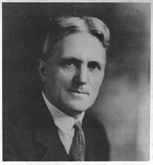
Austin A. Howard was born in 1872 and, by 1905, was already building
radio apparatus. He was a ham radio enthusiast
before WWI and, in 1918, the Navy performed transmission tests using his
station in Chicago. He had an experimental call, 9XG, up until 1922. He
was at the First National Radio Exposition in Chicago in 1921 where he
represented "Electric Specialty Company" which was probably
the forerunner to Howard Manufacturing Company. Howard Manufacturing
Company began building
and selling
radio equipment around 1922.
In 1924, Howard obtained a Neutrodyne
license from Hazeltine (he was the last company to obtain a Neutrodyne
license thus becoming the last company to be accepted into the
Independent Radio Manufacturers, a group of fourteen radio companies that were
the sole legal builders of Neutrodyne radios and the exclusive holders of the Hazeltine Neutrodyne license.) Howard
Manufacturing Company was located in Chicago, Illinois. Austin Howard
was already independently wealthy so Howard Radio Company was operated a
little differently than the other 1920s radio companies. Howard built
modest quantities of very high-quality radios at a fairly leisurely pace and
sold them for hefty prices. Just the opposite of another 1920s
independently wealthy radio builder, Arthur Atwater-Kent, who built
literally millions of radios and sold them for more or less average
prices.
|
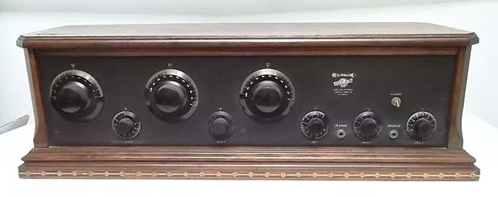
Howard Mfg. Co. -
1925 Model C Neutrodyne
The Model C is typical of
the Howard radios produced in the 1920s. This was a very large
and very expensive five-tube Neutrodyne receiver
that sold for $180 during early 1925 (introduced in March 1925.)
photo: eBay |
Howard changed the company name
around 1926 to Howard Radio Company. Howard was
able to obtain a RCA TRF license in 1927 and then later the Superheterodyne
license. Howard had to build a tremendous quantity of radios per
month to be able to afford the minimum royalty to qualify for the RCA
licenses. Howard's low production rate had to change and, beginning in
1927, Howard's work force dramatically increased along with the company
offering several different
models of radios.
About this time (1929,) Howard Radio Company was purchased by the
Everett Piano Company and they moved manufacturing to
South Haven, Michigan. Everett Piano bought Howard just before the Stock
Market Crash and then tried to work their way into the radio business
during the depths
of the Depression. Everett Piano Company wasn't making any money building
radios so they sold Howard Radio Company back to Austin Howard in 1934.
McMurdo Silver, Silver-Marshall and
the RCA Licensing
- Howard moved the company back to Chicago in 1934 and ended up operating in McMurdo
Silver's building that had been Silver-Marshall. McMurdo and his cousin,
John Marshall, had started Silver-Marshall in the late-twenties. RCA
licensing became a necessity of being in the radio business after the
1930 "Radio Group" Anti-trust suit. The settlement of that suit put RCA
directly controlling almost every aspect of radio manufacturing. The Superheterodyne
circuit was part of the settlement. It had been Westinghouse's property
since 1920 but the government settlement gave the Superhet patent to RCA
with the stipulation that licensing had to be provided for qualified
manufacturers. Large radio companies that could produce huge quantities
of radio, such as Zenith, Atwater-Kent or Crosley, didn't have a problem
producing the large amount of radios required but smaller companies
couldn't directly qualify and that was Silver-Marshall's situation.
Becoming a subcontractor was one way around the RCA licensing and that
was how McMurdo Silver dealt with his lack of a RCA license. By inviting
Howard Radio to move into the Silver-Marshall building and manufacture
radios there, any other radio building for other smaller companies
involved would be covered by Howard's RCA licensing. It was a solution
that benefited not only McMurdo Silver but later Bill Halligan and
others, not to mention Howard Radio.
|
Sears-Roebuck Co. -
Silvertone 5656A - 1937
Sears had Howard
Radio Company build these eight-tube superheterodyne receivers
in 1937. Despite the low selling price of just $49.50, the 5656A
was a surprisingly good performer that offered a RF amplifier stage, variable-coupled IF amplifier
stage, IF gain control (Sensitivity,) a Standby switch,
headphone jack and a built-in 8" Jensen field-coil loudspeaker. |
Bill Halligan and Hallicrafters
- Ultimately, Howard found that it was much more profitable to build radios for
other companies as a contractor and his RCA and Hazeltine licenses allowed him to do
just that. Halligan was friends with McMurdo Silver and had been selling
his very early radios by mail-order since this could bypass the license
requirements. Halligan made arrangements to have his receivers built at
Silver-Marshall by Howard Radio. That allowed Hallicrafters to develop
their radio circuits and use RCA TRF and Superheterodyne circuits,
protected by Howard's RCA license. The Hallicrafters business
ended about August 1936 when Halligan made arrangements with Case and
bought the Echophone Company to acquire their RCA license and
manufacturing facilities.
|
Sears-Roebuck
and Howard Radio - Howard's biggest and most
profitable customer was the Sears-Roebuck Company. Of course,
Sears-Roebuck's "Howard-built" radios were labeled "Silvertone"
as all Sears' radios were. The Howard Radio Company
identification was usually only a manufacturer or contractor
number. Howard Radio almost always used the number #1731 as
their identification. This number was supposedly based on the
Silver building address of 1731 Belmont in Chicago. Typically, a
stick-on paper model label was applied to the radio chassis that
had the "Howard ID" on it. Sears had always been reluctant to
reveal that Silvertone radios were built by
contractors, although almost everyone knew that fact. In the
later thirties, Sears Silvertone radios have no
indication of the contractor-builder of their radios. In
the later half of the thirties, Howard began to build and sell
ham-communication shortwave radios. Some of the communication receivers
were built for Sears-Silvertone but Howard did sell their own brand of ham
receivers with a lineup that featured examples from entry-level
receivers up to advanced-level communication receivers.
Howard Radio Co.
Receiver Design and Build Quality - Howard's communication receivers were designed and
built to be affordable, therefore the chassis
design used what were essentially
broadcast-entertainment radio components. Some of the
small Howard ham receivers
were obvious AM-BC-SW radio conversions to entry-level,
metal cabinet, shortwave receivers that could have been
usable in the stations of neophyte hams.
The quality
level of
Howard communication receivers was similar to the receivers produced by Hallicrafters, Radio Manufacturing Engineers or Breting Radio Company. Howard's
receivers sold for about the same price as the Breting receivers
but were priced less than comparable Hallicrafters or RME receivers. Breting receivers in particular
were fairly crude in their wiring and their mechanical assembly
where as Howard receivers were more professional assemblies
but of an
average quality,
somewhat similar to Hallicrafters and RME. Wiring lead
dress in Howard chassis is mostly "point-to-point" with an
almost "messy" quality to it. Some self-tapping screws are used
along with some rivet-mounting. Copper-plated chassis were used
for many of the receiver models.
|
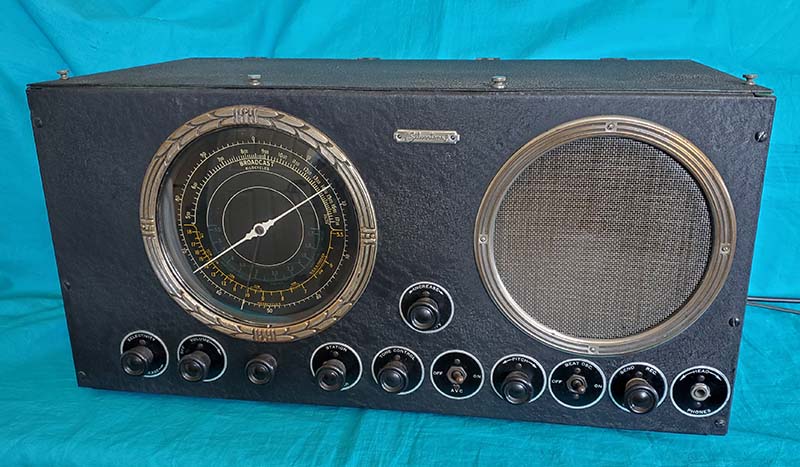
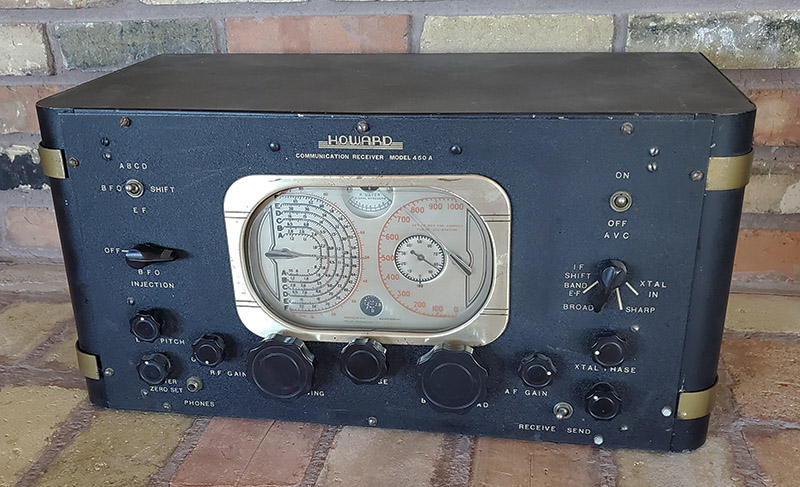
1938 Howard Model
450A Communication Receiver
This was
one of Howard's largest and most elaborate communication
receivers featuring 12 tubes and tuning from .54mc up to
60mc. Other features included dual IF frequencies, a
Crystal Filter, Dual Frequency BFOs, 9 watts of
Push-Pull Audio output and a spectacular tuning dial
system |
The component quality is comparable to Howard's competition
with quality capacitors and some well-known component manufacturers being
standard. Most of Howard's components and mechanical
parts came for manufacturers located around
Chicago. This local purchasing of components was also common with Hallicrafters,
Wells-Gardner, Zenith and other Chicago-based companies.
The engineering design of Howard receivers is similar to Hallicrafters
in that the design had to use purchased parts. The majority of
components had to be standard issue
that could also be used in AM-BC-SW consumer
entertainment radios
and preferably available from Chicago companies. Most of the
communication receiver manufacturers built their products in the
same manner. There were really only two communication receiver
builders at the time that built all of their own assemblies and
purchased only passive components. The two companies were well-known for that fact,...National Company, Inc. and Hammarlund Mfg. Co., Inc.
Howard never
seemed to put a lot of money or effort into advertising and that might be
why Howard communication receivers and his smaller SWL
receivers never really gained a foothold in hamdom.
Nowadays, you'll see Howard Radio communication receivers once in a while though not nearly as
often as Hallicrafters or RME receivers.
WWII and Post-WWII
- Howard's ham
gear line-up ended when WWII began and Howard Radio Company then built
for the war effort. Howard Radio's most famous WWII contribution was as an alternate
contractor for the production of BC-779 Hammarlund Super Pro receivers.
These BC-779 receivers will have a data plate on the front panel
indicating that the receiver was built (or assembled) by Howard Radio Company.
|

Howard-built version of the
Hammarlund BC-779-A Super Pro from ca: 1945
Note "Howard Radio Co." on the data plate
- photo from Ed -djed1 |
Howard Radio
really never came back after WWII ended. The company offered a few table model
consumer radios and a FM converter for a short time. Howard himself was in his mid-seventies by this time so
it's not surprising that the Howard Radio Company was
out of business by 1949. |
|
Profiling Six
Ham Receivers Built by Howard Radio Company
|
|
Sears-Roebuck - "Silvertone"
Model 5656A - built by
Howard Radio Co. - 1936-37
I actually performed this
restoration about twenty years ago. But, for this 2024
write-up, I took this 5656A off the shelf and put it through its paces
to see how well it receives here in Dayton Valley, Nevada. I also
shot all new photos of the 5656A showing the chassis in detail.
As I wrote in 2005, the 5656A is a surprisingly good receiver.
Now, in a fabulous radio-reception QTH with a large array
antenna, the 5656A does an even
better job. Although the top tuned frequency is only 18mc, the
reception on 20M is excellent. Perhaps the biggest disadvantage is
the lack of band spread. Tuning CW or SSB stations can be
difficult. |
|
General
Circuit Description
-
During the thirties,
Sears-Roebuck offered a few different communications receivers built for them by Howard Radio
Company. Their Silvertone Model 5656A was offered from late-1936
through 1937. The 5656A had a similar appearance to some of the very early
Howard-built Hallicrafters receivers, particularly the Super-7
receiver (there was also a similar looking receiver built for
Montgomery Wards.) The 5656A receiver was an eight tube superhet with three tuning bands
covering .55 to 18.0 MC. The circuit featured a 6K7 TRF amplifier, 6L7
Mixer (called a Translator by Howard,) a 6C5 LO, a 6K7 IF
amplifier, a 6Q7 Det, AVC and 1st AF amplifier, a 6F6 audio
output, a 6C5 BFO and a type 5Y3G rectifier. The IF operated at
465kc and featured a variable coupled IF transformer for
adjustable selectivity. The tuning dial was large at eight inches in diameter
with a convex glass cover with fancy "leafed" bezel.
Both the dial and speaker bezels appear to have originally been
nickel-plated but have worn to the bronze-like appearance they
now have. The beautiful multi-colored dial scale somewhat compensated for the lack of any
type of bandspread. An AVC switch was included along with a separate Sensitivity Control (IF Gain
only) and a built-in 8" Jensen speaker. It's likely that the screen-grille
was originally flocked with some kind of mohair as that was typical of
the screen grilles of the day (but, of the several vintage photos showing
various 5656A receiver grilles, some appear flocked with a
light-color felt, one had grille cloth installed and some grilles appear to just be the screen.
There wasn't any felt or glue residue on this screen which
appears to be the original.) The BFO was built on a separate small
chassis that was "cable connected" to the receiver chassis for
power but was electro-statically coupled to the detector. The
Phone jack was capacitor coupled from the 6F6 plate. The 5656A
provided the basic communication necessities and performance
that was adequate for many entry-level hams. The 5656A was
fairly popular and can be sometimes be spotted in vintage ham
station photos. The 5656A selling price was probably around
$49.50 based on that exact same selling price being asked for
either the Hallicrafters Super-7 or the 1936 Silvertone
Super-Eight (also built by Howard Radio.)
Documentation
- The 5656A is documented in Riders Perpetual Troubleshooter's
Manual, Vol. X, SEARS page 33. The basics are covered in the
single page schematic plus the side notes. The schematic is
dated 8-1-36. Although Howard Radio isn't specifically
mentioned, there are several clues to Howard Radio's contractor
identity. The schematic shows the Mixer as "Translator" which
seemed to be something that only Howard Radio called the Mixer
tube function on their schematics. The use of the 465kc IF, although
not exclusive to Howard, was the usual IF that they used. The Candohm resistor in the receiver is from The Motor Co. of
Chicago, the usual supplier of Candohm voltage dividers for
Howard Radio. There may have been further confirmation on the
rear chassis paper stickers but they are mostly missing on my
5656A. |
Silvertone Model 5656A built by Howard
Radio Co. for Sears-Roebuck
SN: 8-A 1853 ca: 1937
Delivered by Airborne Medical
Transport to Virginia
City, Nevada in 2002 |
|
Close-up of Multi-color
Dial of the 5656A |
Unusual Acquisition
- In 2002, back when I had the
Western Historic Radio Museum as a real "brick and mortar"
museum in Virginia City, Nevada, I was contacted by a ham
collector that wanted to sell me a Silvertone ham receiver. He
described the receiver as looking something like a Hallicrafters Super-7.
The price was very reasonable and he offered to deliver the
receiver in a most unusual way. It happened that Ray (the
seller) was a private medical transport charter pilot for the most of the
Western USA. He would fly people that chartered his service from Western rural areas into
larger metropolitan areas for non-emergency hospital surgeries, treatments
or appointments. The radio transaction was to take place a few weeks
later when he was
going to be flying from his SoCal home-location up to Nevada to
do a "pick up" and transport that person from a rural location in Nevada to the Reno
Airport for land transport to one of the Reno hospitals.
He wanted to come up to Virginia City afterwards since the medical
transport was a "drop off" and he only had his return trip to SoCal left. He
wanted to visit the WHRM and he also would bring along the 5656A for me to purchase. This all came off without a
hitch and the receiver was delivered as expected. The 5656A was
in very nice condition with only a couple of exceptions. First,
the grille screen was painted black and that allowed the speaker
cone to be easily seen. Then there were four knobs that were
obviously not original. Everything else looked original and later,
when I started the rebuild and could look under the chassis, I
discovered that the 5656A was all original parts. It was really
hard to believe that nothing had been changed under the
chassis,...no repairs, no modifications,...very unusual for a
relatively inexpensive receiver.
Restoration
- I performed a complete
restoration on this 5656A about 2004. I had to have four knobs
cast from one of the good condition originals. At the time, Larry Bordonaro,
now "Antique Radio Knobs.com", was just starting out and did custom knob casting in
plastic material
that looked just like bakelite. His knob castings were
first-class and indistinguishable from the originals (Larry is still in business - 2024.)
I had to rebuild the tuning system that relied on a
pinch-wheel working against a phenolic plastic drive disk. Internally,
the original paper capacitors were restuffed with polyfilms, the
electrolytic capacitors were replaced using the original cans
and the waxed cardboard box that held the two cathode bypass
electrolytic caps. The resistors were checked and all were close
to spec. I did a full alignment and the 5656A was working to its
likely specifications. The indications were that this 5656A was
used very little when it was new and was probably stored away
somewhere that preserved almost everything about the receiver (like the
proverbial "kept in a closet" example?) |
|
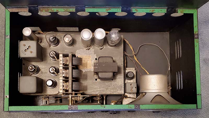
The chassis of the 5656A showing
the separate BFO chassis. The green material is felt padding for
the lid. The chassis is mounted to the bottom plate of the
cabinet and rests on rubber cushions. The front panel isn't
mounted to the chassis directly. When the receiver is taken
out of the cabinet the front panel is only held in place by the
control shafts and the knobs. The loudspeaker is an eight-inch Jensen electrodynamic
field-coil type. There are three dial lamps that can be either
#40 (155ma) or #46 (250ma) types. The steel cabinet adds quite a
bit of weight to the 5656A. NOTE: The 6V6GT is still installed
when this photo was taken. It has been replaced with the proper
6F6G tube. |
More Circuit and Operational Details
- The 5656A, at first glance, seems to
be a
typical AM-BC-SW radio that would have been for the consumer-entertainment market
and probably offered as a
console model radio. The circuit does have a TRF
amplifier stage and a single IF amplifier stage. The chassis was
professionally engineered by Howard
Radio to be built with parts and components that were the same
as those used in their consumer radios but the end product would have all of the basic
necessities of a ham receiver. The BFO chassis is an obvious
addition but it's well-designed and functions quite well. The Variable Coupled IF works from under the chassis
in a manner that's similar to how the Hammarlund Super-Pro
Variable-Coupled IF works but using a rotating pin and slider crank rather than
the Super-Pro's
cam-driven levers with spring-loaded plungers. The Sensitivity control, AVC
switch and the Phone jack are also integrated quite well with
either shielded cable or twisted wire cables to the front panel controls. Tuning is a
little crude being a small phenolic plastic disk that works with
a pinch-wheel type of drive. Without any band spread
provided, tuning is difficult especially for SSB signals (you have to fine-tune with the BFO.)
Of course, in 1937, there weren't any ham SSB signals around and
most hams were on CW. |
Under the receiver chassis
showing its pristine condition |
|
Under the BFO Chassis |
The 5656A does a good job on CW signals
although, like modern SSB, tuning is a little difficult but the BFO can be used for
fine tuning. Actually, the tuning dial's sweep-second hand pointer is very
handy when tuning through a ham band as it allows the operator
to "visually expand" what is really a very narrow section of the main
tuning dial. The 8" Jensen loudspeaker is a good-quality field coil electrodynamic
speaker that sounds very nice on AM signals. The
Tone control does mellow the reproduced sound considerably. |
Performance
- Years ago in Virginia City, I had thought about using the
5656A as a station receiver with a 1937 Utah UAT-1 transmitter I
had but, at the time, the receiver didn't seem to perform
with sufficient selectivity for operation on 75M phone. It was a fine SWL receiver
and the dial illumination for "lights out" listening was
impressive. Well,...that's what I thought back then when
I was in Virginia City,...one of the worst radio locations I've
ever lived in. Nowadays, in Dayton Valley, Nevada, the QTH is
one of the best radio reception locations I've ever lived in.
At some time past I had installed a 6V6GT tube in place of a
proper 6F6G tube, so before testing began, I installed a NOS
6F6G tube. Although the 6V6GT and the 6F6G can be interchanged
and function okay, the 6V6 is a beam-power pentode while the 6F6
is just a pentode. They do sound slightly different with the
6V6's reproduction in a 6F6 circuit sounding a bit shrill. The
6F6 will sound mellow and reveal a bit more bass response (geese,...I
sound like an audiophile.) When using the large Collinear Array antenna, the reception
using the 5656A is impressive for such a "basic receiver." I was
surprised at the signals I was receiving on 20M.
To demodulate SSB
signals, the Selectivity control can be used as an attenuator along with
reducing the Sensitivity control in order to have the BFO
injection to
signal level ratio correct (AVC off, too.) On 40M or 80M, SSB
signal levels can be extremely strong when using a large array antenna and even with reducing the
Sensitivity and increasing the Selectivity, still some
distortion will be experienced. It doesn't prevent demodulation
but the distortion is noticeable. When looking at the schematic
it can be seen that
the Sensitivity only adjusts the IF gain and with the AVC turned
off, the RF amplifier is running at maximum gain and that's not
adjustable. In the thirties, it was common for the ham to have a
separate "receive-only" antenna coupler that not only allowed
matching the antenna for best receive response on weak signals but would
also allow the coupler to act as an attenuator to prevent
"overloading" when tuned to strong signals. One has to
remember that most hams in the thirties were on CW and the
receiver would have the BFO on and the AVC off so overloading
could happen. The ability to attenuate an extremely strong
incoming signal was an easy method to prevent overloading. |
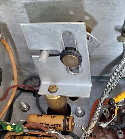
The Variable Coupled IF Control
showing the rotating pin and slider crank type of mechanism for changing
the physical distance between the IF coils to control
Selectivity. The grommet is a bit dried-out but a new grommet
might increase the "drag" and make adjustment difficult. It
works fine now. |
|
This intense level of signal wouldn't happen when using a
smaller antenna but I'm testing using my large Collinear Array
that has some gain, so it's the "worst case scenario" for trying to
successfully demodulate extremely strong SSB signals on 80M and
40M. SW-BC signals are easy to tune
in and sound very nice although it does depend on the broadcast
material. When in Virginia City, I used a
60' EFW with this receiver and the combination of poor location
with an even poorer antenna didn't provide very impressive
results. But, a RF-friendly QTH and a large antenna system will help any receiver, so
the 5656A went from unusable to a receiver that could easily and
successfully be
used on 75M AM. For SWLing, it seems to perform quite well and
will easily receive stations up to the 19M band and even 16M SW
stations are easy to receive with the upper limit of tuning
being 18mc. As would be
expected by looking at the dial, the tuned frequency accuracy is
vague at best and resolution is extremely limited. Most hams at
the time would have had a separate Frequency Standard (a 1000kc,
100kc and 10kc oscillator) that could provide a check on band
edges. Many hams, especially entry-level hams, would have used a
crystal-controlled transmitter and would know their operating
frequency, although on-the-air QSOs were usually somewhat
"split-frequency" because of the multitude of crystal-controlled
transmitters. There isn't a remote standby provided but there is
a front panel standby switch.
As to disadvantages when using
the 5656A,...the lack of band spread is foremost and makes
tuning in CW or SSB signals relatively difficult. Using the BFO
for fine tuning helps. The tuning dial's lack of resolution and
very small ham band spans doesn't help the tuning situation. This
again relates to the lack of band spread. Using the split-second
hand to concentrate your vision on that scale will give the
impression that the ham bands have a little more span. It helps
quite a bit but still covering all of 20M only takes from 50 to
56 on the split-second dial. Overloading on strong signals can
be a problem but it depends on the antenna size and gain. Using
the Selectivity as an attenuator works most of the time and more
selectivity doesn't hurt on CW and SSB. All in all, the 5656A is
a decent performer with some limitations that should be expected
for the time period in which it was produced and the design
limitations due to its relatively low selling price (it's
difficult to imagine but $49.50 in 1937 is equivalent to
$1075.00 today in 2024,...WOW!) Though it
certainly could be used as a vintage ham station receiver on
75M, its success would depend on the user's motivation and
experience with using pre-WWII receivers "on the air."
|
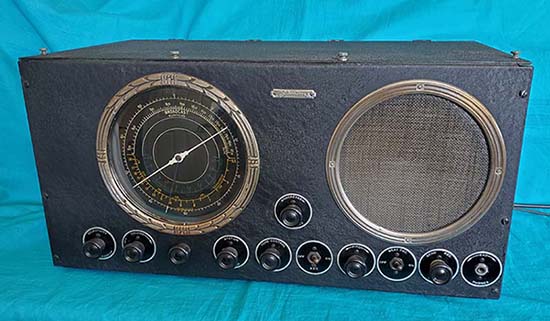
Sears-Roebuck -
Silvertone
STANDBY - Model 5752 - built by
Howard Radio Co. - 1940
The Model 5752 is a nine tube, single preselection superhet with two IF amplifiers, crystal filter, electrical
bandspread, R-meter, switchable AVC, BFO with front panel frequency
adjustment and a single-ended 6V6 audio output all built onto a copper
plated chassis. Tuning range is in five
bands covering .55mc up to 40mc. An external speaker was required. Dials
were illuminated but the R-meter wasn't. Dates from 1939 to 1940. The
Model 5752 was built for Sears by Howard Radio Company.
One certainly notices the similarity of the
Silvertone
STANDBY's appearance to that of the Radio Manufacturing Engineers
RME-69. It had to be a deliberate design "copy" of the RME-69 but what
would have been the reason? A clue might be in the name "STANDBY." At
the time, many hams believed they should never be without receiving
capability. If the main receiver was down for repairs, then the
"standby" receiver could be used. The active and prepared ham would always have a "standby" receiver.
If the station receiver was a RME-69 or RME-70, then this Sears "look-alike" would
blend in and appear to be another RME product. It seems unlikely that
Sears' "RME-69 look-alike" would have been styled to fool someone into
thinking this Howard-built receiver came from RME, especially at the
price Sears was selling it for. It's more likely that the designers
imagined that a ham looking for an inexpensive "standby" receiver would
find the Model 5257 appealing because of its familiar appearance.
No restoration has happened on this "STANDBY" receiver,...at
least, not yet. One can note that to the left of the tuning dial
escutcheon there is a small red pilot lamp jewel. This superfluous addition will be
removed as soon as work starts on this receiver. It's obvious
that some mechanical rework is going to be required since the
dials are obviously tilted somewhat. More to come,... |
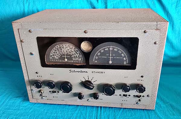
Silvertone STANDBY
Model 5752 built by Howard Radio Co. ca: 1940
RME-69 look-alike, minus the RME price,...and
performance |
| This Silvertone
STANDBY receiver had belonged to KB6BKN Walt Schivo (in
fact, Walt currently has a photo of this receiver on his QRZ page.) For a
while, there were some Internet postings about this very same
receiver with speculation that it was a RME product. Walt sold a
lot of his gear to Ham & HiFi about five years ago and that's
where I found the receiver in July of 2019. Once I had the receiver and could thoroughly examine it
didn't take too long to discover that it had been built by Howard
Radio Company. |
|
Howard Radio
Company - Model 437A - 1940-42
The Model 437A was the last
evolution of the 435 and 436 models of nine tube receivers that
were mid-level communication receivers. The 437A covered .54mc
up to 43mc in four tuning ranges with band spread capability.
The IF operated at 465kc and there was an optional Crystal
Filter and an optional S-meter. This 437A has the Crystal Filter
option installed but not the S-meter. As the 437A with Crystal
Filter, the selling price of the
receiver shown would have
been $69.75 in 1941.
Many of these
smaller models of
Howard receivers had a matte silver-based chemical treatment for
the dial finish that nowadays is
almost always is found in terribly corroded condition. This particular
437A's dial is in excellent condition (it may have had a
protective coating applied when manufactured but more likely the
pristine condition of the dial is due to the dry climate here on
the East Slope of the Sierra.) In fact, the entire
receiver was cosmetically in very good condition and the chassis
was essentially original. Unfortunately, although I took the
time to clean this 437A and photograph it, I didn't restore it
to operational condition. In fact, I sold this receiver quite
some time ago (and I don't even remember who bought it since I
sold it "out of the museum") but at least I did keep the photograph. |
Howard Model 437A with Crystal
Filter option ca:
1941
A transient relic now in
other hands |
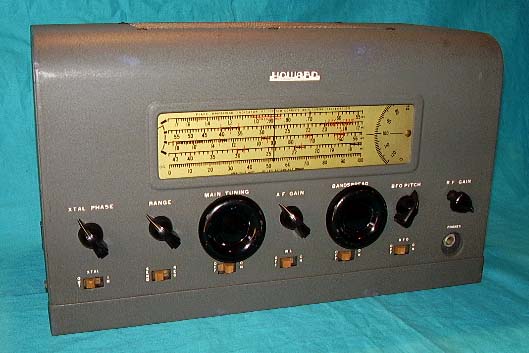
|
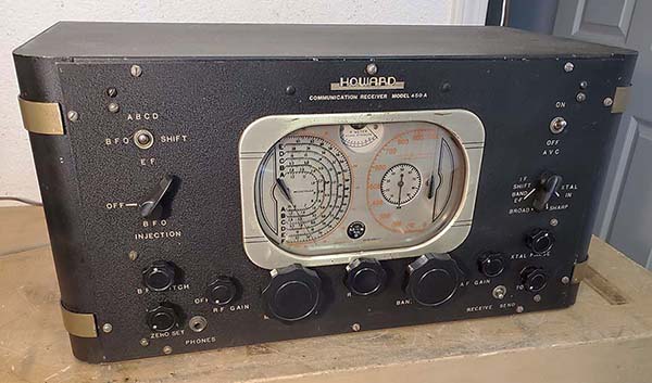
Howard Radio
Company - Communication Receiver Model 450A - 1938-39
I was tipped off that this Howard 450A was
going to be at the May 11, 2024 Spring SNARS (Sierra Nevada Amateur
Radio Society) "Cabela's Swap Meet" - so called because the ham
swap meet is held in Cabela's parking lot in Verdi, Nevada (10
miles west of Reno.) The 450A was part of a very large selection
of some really nice "collector" ham gear that was brought to the
swap in a 14'
moving van by Ham and Hi Fi of Sparks, Nevada. Of course, at a swap
meet you have to "take your chances" since a detailed inspection
isn't really very practical - "as-is" or "as found" is the
expected and typical condition. However, the 450A looked very complete and the dial was
magnificent, so the purchase was made. This write-up has a lot
more information than the proceeding restoration write-up on the Silvertone 5656A since this write-up was composed as I was
restoring the 450A receiver. So, expect the typical OCD-type of
restoration write-up presenting every bit of minutia I find
(with many photos.) How the multitude of minor problems were corrected
will be covered and
eventually how well (or poorly) this Howard communication receiver performs.
|
|
The Model 450A was one of Howard's largest
communication receivers at 12 tubes and a tuning range that
spanned .54mc up to 65mc in six tuning ranges (only the Model
490 had more tubes at 14 total.) The Model 450A was one of a
few receivers available at the time that tuned the 160M through
10M ham bands and included 5M coverage. The smaller Model 440 was nine tube
receiver with a similar appearance but without 5M coverage, the dual IF,
push-pull audio, the "stop watch-like" band spread logging
dial,
the band-in-use indicator and, like many of Howard's larger
receivers, the crystal filter was an optional
installation.
The Model 440 sold for $84 in 1938. The Model 450, also from
early-1938, featured additional tuning ranges increasing the coverage up to 65mc
however when going to bands E and F a different IF of 1560kc was used and the RF
amplifier was
bypassed on the highest frequency band since the 6K7 RF amplifier
tube didn't have very much gain at VHF. The Model 450 sold for $87
and $10 extra if the crystal filter was installed. The Model
450A was introduced within a very short time as the Model 450's
replacement (still in 1938.)
The Model 450A had basically the same features
as its predecessor but now the band F antenna input actually was
a TRF transformer to the Mixer grid where before it had just been a LC
input. The VHF antenna terminal had been A-G two-terminal and
was now A-D-G three terminals. The dual IF of the 450 was
basically unchanged for the 450A. The ABCD IF was 465kc
(frequency coverage from .54 to 16mc) and the EF IF used the
same 465kc IF amplifier tubes but had entirely separate IF
transformers that were tuned to 1560kc and switched into the IF
circuitry the Crystal Filter/IF Shift switch. Frequency coverage
from 16 to 65mc was available on bands E and F. The 1560kc IF helped
reduce the rampant images
that would be encountered on bands E and F. With single preselection (one TRF amplifier,) images on
A,B,C,D bands
probably wouldn't be encountered until around 15mc, depending on the antenna
used and the strength of the signal producing the image. With
the 1560kc IF use (beginning at 16mc,) images would appear 3.12mc
below the transmitted frequency which tended to put the image
response out of the passband of the receiver's front end
selectivity, especially with band E also having a preselector
stage. Two separate sets of antenna terminals are provided on the
back of the chassis. Both are three screw terminal types marked
A-D-G. One antenna input is just for Band F (5 meter band-VHF.)
A vertical whip antenna 59" tall is recommended (with an 8" wire
connection to the antenna terminal) for 5 meter reception. The antenna input for Bands
A-E is for any type of standard balanced or unbalanced antenna
(with resonant antennas providing the best performance.)
The
crystal filter was switched out of the circuit when IF SHIFT BAND
E-F was selected (that eliminated the need to have two crystals,
465kc and 1560kc,
in the Crystal Filter circuit.) The BFO had a variable injection
level adjustment in addition to a frequency control (pitch.) The
1st AF amplifier used a bias cell for the grid (these were
popular in the late-thirties and were very small batteries that
fit into a special holder, some were solder-in types, usually providing about -1.5vdc bias voltage.) A phase
inverter type of audio circuitry was used. The audio output used
push-pull 6V6 tubes and 9.5 watts output was claimed with
impedance outputs of 5Z and 500Z from the internal audio output
transformer. The entire chassis and shielded box for the IF
amplifier/Xtal Filter are both copper plated. A 10" PM loudspeaker was
available in a matching housing. >>> |
|
Howard Communication Receiver Model
450A ca: 1938 "as
found condition - May 11, 2024"
The
industrial-scientific instrument-type dials appealed to
techno-minded hams but note that the glass dial cover has
slipped out of its mounting clips and the top edge of the glass
is showing. |
| >>> Selling price for the 450A was $95.45 and with the optional
crystal filter installed the price was $105.45 in 1938 and 1939. The selling price of $105.45 put the Howard 450A at about the
same price as the larger Breting receivers (the 14AX or the 40)
and the Patterson PR-15 that was then being built by Pierson-DeLane.
The larger communication receivers from the big three, National,
Hammarlund and Hallicrafters, or even RME, were typically at least 50% higher
in cost, so price was certainly an important factor in the
Howard 450A sales. But, even $105 in 1938 was quite expensive
being equivalent to about $2200 today (2024.) Besides the
comparatively low price, there was the
attraction and the visual appeal of the 450A with its impressive
dials looking like whirling stop watches, pressure gauges and barometer
needles.
The 45kljhlkjh0A's industrial-scientific instrument-type appearance must
have prodded prospective techno-minded ham buyers with their
purchasing decision. |
|
| The Dual IF
Function - The IF on Bands E and F, or 16mc up to
65mc, operates on 1560kc. This 1560kc IF uses two dedicated IF
transformers that are specifically for 1560kc and function with
the two 6K7 IF amplifier tubes. When selecting to either Band E
or Band F, the IF isn't switched along with the Band Switch
function. The operator must also place the Crystal Filter
switch to "IF SHIFT BAND E-F" and the BFO SHIFT toggle switch
has to be placed in the E-F position, if the BFO is to be used.
When using Band A, B, C or D the 465kc IF must be used. The
465kc IF has two dedicated IF transformers specifically for
465kc and they will function with the two 6K7 IF amplifier
tubes. For these bands (.54 to 15mc,) again, the band switch
doesn't change to the 465kc IF amplifier circuitry. The operator must set the Crystal Filter switch to either BROAD or SHARP for no
crystal filter or to XTAL IN for crystal filter operation. The BFO
SHIFT toggle switch has to be placed in A-B-C-D for 465kc
operation. Documentation
- Fortunately, the Howard 450A is documented fairly well in
Rider's Perpetual Troubleshooters Manual Vol. X, pages "HOWARD
PAGE 10-28 to 10-31." The pages include the schematic, the
component layout for both the top and bottom of the chassis,
color codes for the transformers, receiver specifications and the
alignment procedure. There are many online sources to view any
of the Riders PTSMs. The easiest to use is at
www.worldradiohistory.com with all of the Riders manuals
(selectable by Volume number) in PDF format. Unfortunately, BAMA edebris doesn't have an
online manual or any documentation on the Howard 450A.
|
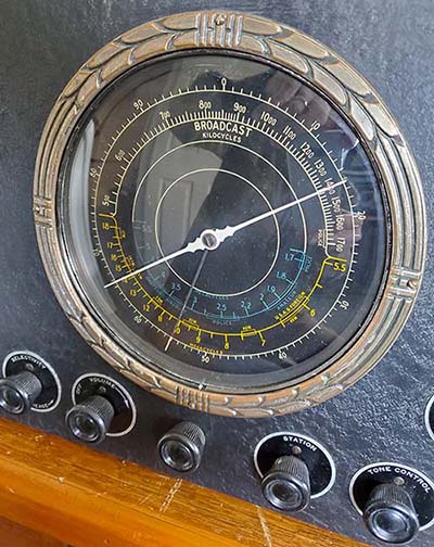
| Dial Details
- The dials are glass with multi-color silk screened
nomenclature on the back side. With the matte silver back plate,
the glass dial is spaced slightly above the silver plate giving
the appearance of depth. The illumination
is from the top edge of the glass using two #47 lamps. The main
tuning dial scale has color coded indicators on the linear
scales with red for amateur, blue for aviation, yellow for
police and green for shortwave relay broadcasts. Some 450A
receivers had black back plates and were fitted with the glass
dials that had white nomenclature along with the red, blue,
yellow and green dial scale indications. The convex dial cover
is also glass. The stop-watch logging pointer is recessed
slightly making it appear as a separate indicator scale. The "band-in-use" indicator
is an white-on-black plastic scale mounted to the band switch
shaft and shows through a hole in the silver back plate. The
"band-in-use" indicator also shows which IF should be used for
the particular band selected.
The "R" meter is also mounted behind the silver metal plate and shows
through a hole. A close-up of the dial is shown to the right. 450A Tube
Line-up - RF Amplifer - 6K7, Mixer (called a
"TRANS" on the schematic - Translator, a Howard
moniker for Mixer) - 6L7, HF Oscillator - 6J5G, First IF
Amplifier - 6K7, Second IF Amplifier - 6K7, Detector/AVC/First
Audio Amplifier - 6Q7G, BFO - 6J7G, Voltage Amplifier (R-meter)
- 6J7G, Audio Phase Inverter - 6J5G, Push-Pull Audio Output -
6V6G (2), Rectifier - 80. It's interesting to note that many of
the tubes that could use metal octal types are specified as "G"
or glass envelope tubes operated without shields (pin 1 is
grounded so metal tubes could be used and shielding would then be
provided.) Some receiver designs would use glass tubes for
oscillators because the glass envelope without a shield would run cooler than a
equivalent metal octal version and might possibly have less
thermal drift. The Detector/AVC/First Audio
Amplifier would operate at a fairly high level signal and shouldn't
pick up any noise so the use of a glass tube might have been for thermal reasons.
In almost any vacuum receiver, the audio tubes and the
rectifier will almost
always be glass tubes because of the heat involved with their
operation. |
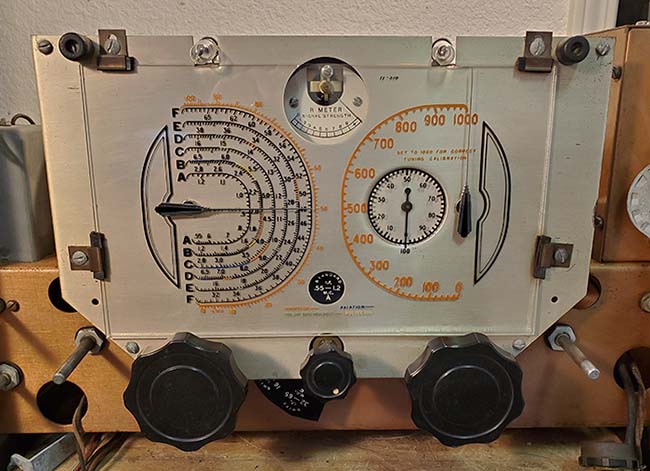
450A Glass Dial - A Multitude of
Indicators |
| Preliminary Inspection
- May 18, 2024
- The 450A chassis shows signs of endless repairs that were
accomplished at a "worse than amateur-level workmanship" both in technique and ability.
It's obvious that the Candohm resistor was
open and has been repaired poorly with sloppily installed
resistors replacing the open sections. The 2.5K 0.5W section of the Candohm
was replaced with a 10 watt vitreous-enamel coated Ohmite
resistor, certainly "over-kill" and showing the lack of
comprehending the basics of Ohm's Law on the part of the repair
technician. Most of the capacitors have been replaced with a
variety that is either because of repairs using "junk box parts"
or that the repairs took place at different time periods. Fairly
modern Orange Drops are installed here and there implying that
some repair work was performed in the last couple of decades.
The few vintage capacitors remaining are Aerovox brand but even
they aren't original to the 450A. The electrolytic
"metal can" capacitors appear original but have a USN "anchor" stamp on top,
so they are more than likely very old replacements
since they are both dual 8uf cans. The schematic shows a single
8uf can and a dual 8uf can being used originally.
I checked
the power transformer and it's a physically
smaller replacement
that doesn't quite fit correctly. Two pieces of 1/2" steel channel
are used for mounting adaptors making the replacement obvious.
This transformer does have close to the standard voltage
outputs but it appears too small for a 12 tube radio set (should
be HV 375-0-375vac ~.120ma, 6.3vac~4.25A, 5.0vac~2.0A.) This power transformer
looks like it was for an eight-tube set. The original power
transformer was probably a Stancor since they, like Howard, were located in
Chicago. It shouldn't be too difficult to find a correct spec Stancor power transformer. The filter choke tested
okay.
The audio output transformer has an open plate to CT
winding. It's the dual secondary of 5Z and 500Z with a rating of
about 10 watts that makes an exact replacement difficult to find. The
closest that I can find (in my stock) would be out of a National
HRO-60. This audio output transformer is for P-P 6V6 tubes and
has a secondary for 8Z and 500Z. It's a frame-type transformer
and should be a fairly close fit. Another "Howard issue" is that
the original audio output transformer and the filter choke are
both mounted using rivets compounding the replacement task. |
Mechanical Inspection
- The entire chassis is copper plated and the copper is in
pretty good
condition with just a few small corrosion spots. The entire IF
shielded box is also copper plated and in fairly good condition.
There's a non-original punched hole in the rear apron of the chassis that may
have been for an auxiliary socket. There's also a 1/2"
hole on top of the chassis behind the tuning condensers. I
doesn't appear to have any function and doesn't look original.
Both holes are very neatly done (unusual.)
Typical of some receivers designed at this time, the tuning
condensers are mounted on rubber cushions which have compressed
and dried out. The rubber bushing mounting of the tuning
condensers involves the entire front dial backing plate with the
front of the MT condenser and the BS condenser mounted to the
plate, then the plate is cushion-mounted to the front chassis
apron and the rear of the MT and BS condensers are mounted to
the top of the chassis with cushions. This arrangement allows
replacing the cushions without unwiring the MT and BS
condensers.
The RF Gain control shaft is extremely worn and
wobbles quite a bit. The AF Gain control is not worn. The BFO
air variable has a strange "feel" to it,...it's like it's rubber
mounted but it isn't. Further investigation will be necessary to
see what's going on with the BFO.
The Main Tuning uses dial cord
for the drive but the Band Spread uses a tuning belt. Belts are
always difficult to replace and even if the correct belt is known (JFD
#21 in this case) it may not fit correctly because of wear. The
450A has the MT/BS condensers mounted to the backing plate and
both tuning shaft bearings are in the same backing plate so the
dimensions can't change, therefore, a belt with an inside
diameter of 3.5" should work. Using square rubber extrusion
works fairly well for custom rubber
belts that are cut to size and then glued with super glue.
However, they
don't last indefinitely. Likewise,
O-rings will only work for a short while before drying out and
breaking (O-rings aren't designed as "belts" so it's not
surprising that they don't last very long in that function.) The original belts lasted a long time because they were
a fabric sandwich with impregnated rubber. The trouble is, these
belts are at least 70 years old, so they might be non-pliable
nowadays.
The glass dial is in perfect
condition. The champagne-silver backing plate is excellent. The glass dial
cover needed some padding where the clamps contact the glass.
The pads allow tightening the clamps to slightly compress the
padding and secure the glass without breaking it. The receiver front
panel is in very good condition and the cabinet is in good
shape. The bottom cover is missing but would be easy to
replicate. |
| Past Repair Work
- Often times "worse-then" amateur-level repairs do more damage then actually
repairing anything. When dealing with low-cost, high tube-count receivers, such
as the Breting 12 or 14 and the Patterson receivers, it seems
that these receivers required many more repairs than comparable receivers from
the Big Three (National, Hammarlund and Hallicrafters) or RME. I'm not sure why this is happens but the
quality of components doesn't seem to be a factor. The passive
components are name-brand parts,...same as used by the Big
Three. The exception might be that the power transformers used
were rated for intermittent service, which is common for
consumer-entertainment radios, and then the ham-owner exceeded that
operational limitation by having the receiver powered-up for
hours-on-end. Also, often problems discovered seem to have
been caused by carelessness or inexperience resulting in circuit
component damage on an extensive level. Most of the problems
seem to have been with the power supply section and the audio
output section, which is where the components are "pushed" to
their maximum ratings and where most failures would naturally
occur. Although one does run
into these types of problems on National, Hammarlund,
Hallicrafters or RME receivers once in a while, the low-cost,
high tube-count
receivers from Breting, Patterson and, apparently Howard, all seem
to suffer from what seems like a litany of endless repairs that were accomplished by
amateurs with little or no experience in troubleshooting or in
the proper techniques of repair work. In almost all cases, these
receivers will not function correctly or don't function at all.
The Plan - The
Howard 450A is going to require a complete "strip out"
of the old sloppy repairs, the incorrect parts, the
modifications and the defective parts. This is usually what has
to be done with ham radio "kits" but so much of the 450A has
been tampered with, it almost has to be treated like it was a
"kit" that was assembled by someone lacking any experience. The
original sections of wiring will remain installed. Any original
components that can be used (tested in spec) will be used but
all replacement components will be of the original style and
vintage that test as usable. Then the chassis will be rebuilt
exactly to the schematic with component placement as shown in
the layout drawing. >>> |
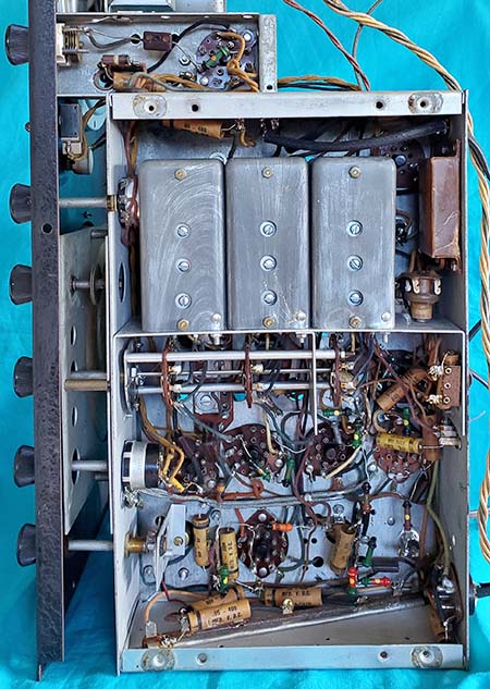
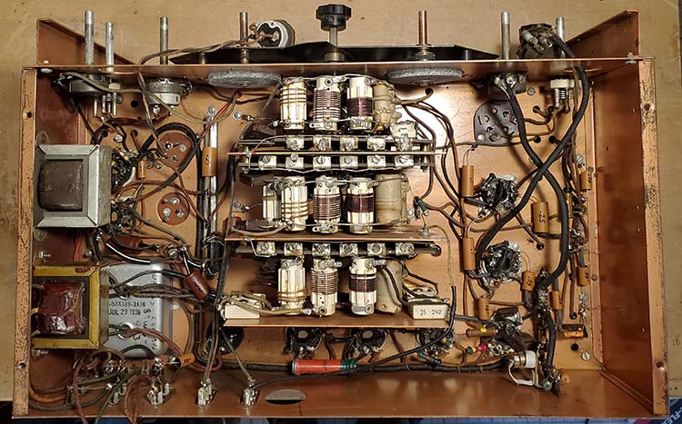
|
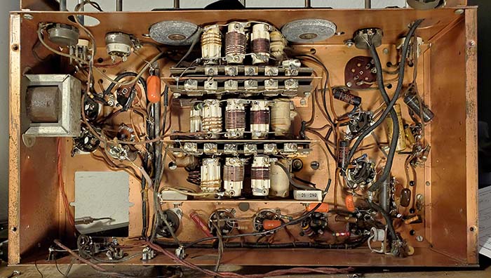
Under the chassis of the Howard
450A with the under-size power transformer removed and the bad
audio output transformer removed. Note the many non-original
capacitors and resistors besides the terrible wiring lead dress. A
lot of that "messy looking wiring" is original. Howard routed
some wiring in a harness but most wiring is "point to point." |
>>> All paper dielectric capacitors
will be polyfilms installed into vintage Aerovox shells to
preserve the under-chassis appearance as much as possible (this
is just a "plan." UPDATE: The Aerovox
caps are replacements, the original Howard capacitors of which
only two have survived just have a value and part number, no
manufacturer shown.) For the audio output transformer,...the transformer from the HRO-60 is perfect. It's the same
physical size as the original Howard transformer and has
nearly the same specs. The primary is for P-P 6V6 tubes and the
secondary is 8Z and 500Z, so it's a very close match. The original
power transformer dimensions were 3.5" x 4.0" and it was a
tub-mount. So far I've found one power transformer that is very
close for all of the necessary windings but it has one extra
winding that produces about 25vac. This transformer is the
correct size but uses four bolts for mounting where the original
power transformer used two bolts. The replacement xmfr is
ink-stamp dated
July 29, 1938 and has a hand-written note indicating it came out of a
large Wards
(Wells-Gardner)
radio. Some of the 13 and 15 tube W-G radios had a 25vac winding for
four series wired 6 volt tubes. This W-G transformer will work
and would look stock but I still have many other power transformers to
go through and I might find one that's an exact match.
Cleaning Begins -
For now, I've cleaned the chassis with WD-40 followed by Glass
Plus. It was actually quite dirty and responded well to the
cleaning. I had to replace the two front rubber bushings that
mount the tuning dial backing plate. The original rubber bushings had
disintegrated so the backing plate would move around. The top
chassis rubber bushings for the rear mounting of the MT/BS
condensers were in good condition. I ordered a JFD #29 tuning belt.
If that works, I can reassemble the tuning
dial.
Belt Update - May 25, 2024 - The
JFD #29 tuning belt arrived today and, while it's not
what's called for in the JFD index (#21 is,) I went by what I
measured. The JFD #29 was 11" inside circumference or 3.5" ID.
The fit was perfect but the belt kept derailing while tuning.
However, when I mounted the front dial plate that provides the
front bearing for the tuning shafts, then the shaft was
perfectly horizontal to the vertical pulley on the BS condenser drive and
the belt then functioned correctly and didn't derail. |
| Stripping the
Chassis of Undesired Parts - May 26, 2024 - I removed the defective audio
output transformer by drilling out the rivets. The wire leads
were clipped at the bad transformer because I will use them to
extend the leads on the HRO-60 transformer. I unsoldered all of
the wire leads that were from the undersize power transformer.
The transformer was then dismounted and removed. When it was
placed next to the W-G replacement transformer, the size difference was
surprising with the W-G being about 50% larger (yet it fits into
the chassis opening and aligns with the "shadow outline" from
the old "long gone" original.) The only problem is
that the W-G requires four corner holes for mounting where the
original used two center-side mounting holes (and there
aren't any center holes in the W-G xmfr.) I still have a few
more transformers to look at but so far the W-G is the best
replacement other than requiring drilling four mounting holes. (No
exact replacement was found. The transformer I'm going to use is
probably from one of the 13 or 15 tube W-G radios. These radios
had a 25vac winding for four 6.3vac tubes wired in series. The
25vac winding isn't
necessary for this application and the regular 6.3vac winding
can supply the filament current needed for the 450A. The +HV
winding is typical for P-P audio applications rated at 8 watts
being about 370-0-370vac (with 120vac on the primary.) With the rectifier voltage drop and
the IR drops involved, the resulting B+ at the 6V6 plates should
be around +250vdc but this is also dependent on the AC line
operating voltage which probably should be 115vac for this
receiver.) Next is to remove all of the modern parts installed. To make
reassembly easier, I'll take a close-up
photo for reference. Usually, when doing a "strip-out" on a
ham-kit receiver, the documentation will have a detailed drawing
of all of the components and wiring as part of the assembly
instructions. The 450A wasn't a kit, so the only drawing shows
just the placement of the capacitors and resistors without any detail
on wire routing. The photograph with the schematic
and Howard's component location drawing will all be used when
doing the reassembly.
Any modern resistors that are replaced with correct vintage resistors
will have to have the vintage resistor values checked. I have a
large quantity of late-thirties "dog bone" resistors that are NOS. Over half
of the resistors checked have drifted in value by 50% and some
are 100% or more higher in value than marked. Many of the
original resistors are still present under the chassis but those
will have to be checked for drift. The original resistors seem
to be all "dog bone" types except for three straight-end BED
resistors but with a color band replacing the dot (not the
normal color-band configuration.) Those three straight-end types
appear to be originals and are (2) 50K and (1) 500K.
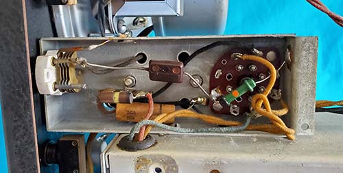
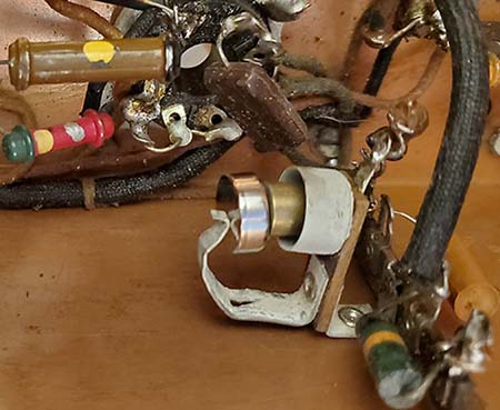
|
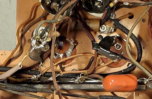
Showing the type of
sloppy repairs performed on the voltage divider sometime in the
past. The obvious "over-kill" 10W Ohmite resistor with a ring of
glopped-on solder is the B+ input to the Candohm. Black
electrician's tape, hook splices and tack soldering show
that this is worse-than-amateur-level work. Due to a multitude of errors, the receiver never could have worked afterwards
(but almost certainly the perpetrator blamed Howard for
building a such a "crummy" radio.) |
| The Candohm
Voltage Divider
- Candohm dividers always
were very prone to opening up on the various sections. Usually,
an associated bypass capacitor would fail and the increased
current would exceed the wire wound sections and one or more
sections would open up. Most repairs would parallel a new
resistor connected to the terminals of the open section to make
the repair. This approach would probably result in the neatest
appearance since finding an original Candohm would be impossible
and repairing the bad Candohm would require rewinding the
burnt-out sections with new ni-chrome wire and that could only
be acccomplished if the original could even be taken apart (they
weren't designed for repair,...just replacement,...and maybe not
even that since it's riveted to the chassis.)
It's really quite
easy to calculate the entire Candohm divider network and the
dissipation requirements. First, total all of the Candohm resistances
(17.6K.)
Observe what the B+ level is at the input to the Candohm
(+245vdc under load,...+305vdc at the rectifier, IR=60vdc across
365Ω choke=~160mA total B+ current draw.) Then
I=E/R will give the total current through the Candohm (245/17,600=14mA.) The I²R=P
will give the dissipation of each resistance in the Candohm. The
TOTAL dissipation across the entire Candohm is about 3.5
watts (so 10W for one section was definitely "over-kill.") The
greatest dissipation is the 10K section at 2 watts (and that
section is okay.) Generally, dissipation (watt rating) is
doubled as a safety factor since the calculations are based on
the receiver operating with normal current draw but at "turn on"
much higher voltages will be experienced (although less current)
until the tubes warm-up and start to draw current off the
divider taps. Since the
resistance values are already known from the schematic, only the
dissipation of each section is in question. The current draw of
the operating circuit off of each Candohm tap also affects the
total current through the divider to a certain extent but for
dissipation requirements, the static voltage drops will be close
enough.
The affected resistor in the 450A Candohm is the open input
resistor that can be replaced with a 2.5K 6W (.5W actual
dissipation.) The 1.5 section is okay (.3W,) the 3.6K section is
okay (.72W) and the 10K section is okay (2W.) The dissipation
levels shown in parentheses are calculated with +245vdc B+ (from
schematic) and are probably slightly lower than if the receiver
was operated on 120vac line voltage (the +245vdc was probably
specified with 110vac to 115vac line voltage.) >>> |
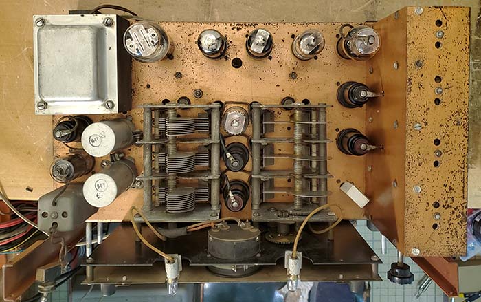
Howard 450A Top of the Chassis
(W-G replacement Power Transformer
Installed)
Note the Band Spread condenser only has one rotor plate and one
stator plate per section. This "Howard" modification is shown in the Rider's PTM
information and indicates that one rotor plate and stop per
section can be removed to
reduce vari-C and thereby increase the "spread" for better fine
tuning response. Unfortunately, this mods RUINS the band spread
action entirely. |
| >>> But, even if the B+ actually was +330vdc as the
receiver was "warming up" before the tubes start to draw
current, the resulting total Candohm static dissipation
only increases from 14ma to 18.75ma and the 2.5K or the 1.5K resistors'
dissipation only increases a few tenths of a watt (total
Candohm dissipation at +330vdc would be 5 watts but it would
only be for about 15 to 25 seconds.) The result is a lot of
variables that aren't going to affect the overall function of
the voltage divider. The replacement resistor can have a much
higher dissipation rating and, with modern resistors, their
physical size is quite small. So I could use the exact
resistance value that was required, I ordered an older NOS
replacement wire wound resistor. Even though the replacement
resistor has a 6W dissipation, physically, this type of resistor
is only 1" long and .250" diameter, so mounting it on the Candohm terminals won't be too
obvious of a repair (conveniently, the resistor is black and
that also helps to hide its installation.) |
| Push-Pull 6V6 Specs
- For around 10 watts output power,
the 6V6 plate voltage should be around +250vdc. The screen
voltage will also be around +250vdc. The grid bias is determined by
the value of the cathode resistor (250Ω) resulting in about
-15vdc bias that shows up as +15vdc on the cathode. W-G Power Transformer
Installed - May 28, 2024 - Just a very slight
adjustment of the square hole was necessary for this replacement
to fit. About .090" was removed from the front-most short side and that was
enough for the transformer to "drop in" the tub hole. I marked
the four holes necessary for mounting, drilled them and then
mounted the W-G transformer. I tested the transformer several
times just to be sure that the removal of the 25vac leads
(cutting, insulating and placing the leads inside the bottom
cover) didn't
cause any problem and to verify the operation of the transformer
was as expected. I didn't wire in the W-G transformer yet since
I still need to "strip out" the modern components and
sloppy repairs
first.
|
The Audio Output Transformer
- This transformer is from a parted-out HRO-60 receiver with a
P-P 6V6 audio output stage. The specifications for this
transformer are almost perfect as a replacement and, physically,
it's exactly the same size as the defective original.
Installation was straight-forward with no problems. Since some
of the HRO-60 transformer's leads are shorter than what was
required, I had to splice the original transformer's wire leads
to get the length needed. Although one would first think that
shrink tubing should be used to insulate the splices, shrink
tubing looks "too new" (because it is.) In the late-thirties splices
were insulated either with friction tape or with lacquered
tubing. I used the lacquered tubing if possible and friction tape
as a second choice. More
Stripping - May 30, 2024 - I removed all wires going to the
Candohm. Several were not connected to the correct voltage taps. I
marked all wires (wrapped tape ID) after verifying were the wire came from so, when
reconnected, the circuit will have the correct voltages. I found
a wire going to the LO tube socket that was a broken solder
joint. This was under the coils and would have been almost impossible
to spot except I was tracing wires to the LO and happened to see
the broken joint when I moved the wire slightly. Luckily, there
was sufficient spacing between the LO vertical shield and the LO
coils to access the tube socket and the wire was soldered back
onto the socket terminal. Removed all components and wiring to the rectifier
socket and both 6V6 sockets. Only one resistor was original. 6V6
cathode resistor was a replacement that wasn't the correct value. |
| Wire Harvesting
- I'm sure I'll be needing some vintage hook-up wire as I
rebuild the 450A. The hook-up wire is solid conductor 22ga. TC
with "push-back" cloth insulation. Almost identical wire was
used in Hallicrafters receivers about the same time. I have
several SX-28 "junk chassis" that can provide this type of wire
in the correct color insulation. Having ample wire supplies will
allow for proper routing when doing this rebuild. Lead
Dress - The Howard 450A component drawing shows
the proper placement of the capacitors and resistors.
Unfortunately, it's obvious that Howard's assemblers didn't
install ALL of the components exactly as shown on the assembly
drawing, so there will be a few capacitors placed differently
but they are "as originally installed." Some of
the wiring in the chassis uses a harness. The other
wires look randomly installed. Comparing the original wiring in
the Silvertone 5656A to the 450A, it appears that Howard wired
the tube heaters and some of the B+ in the harness while the
signal wiring was "point to point" wiring. At the time, "point
to point" was a lead dress style that believed that the
shortest, most-direct wiring resulted in less capacitive
coupling in the signal circuit so less losses and better
performance resulted. I'll be rewiring the 450A in this manner to
adhere to "Howard's style" of wiring.
Capacitors -
Since so much of the under-chassis isn't original I don't think
there's really any point in restuffing the few remaining
original caps and adding non-original shells into the mix. So,
I'm going to use yellow-jacket polyfilms but, as I've done in
the past, I'm going to paint the capacitors to hide the hideous yellow color of the modern capacitors.
Resistors needed will be as close as I can find to the original
style. The effect this creates is at first glance the under the
chassis appearance is that of an original receiver. Close
examination would easily show that the painted capacitors were
obvious replacements. |
Power Transformer and Audio
Output Transformer - Jun 7, 2024 - Wired the
power transformer into the circuit. Mounted the HRO-60 audio
output transformer and wired the secondary into the circuit. I
had to recondition the Phone Jack wiring and reconditioned the
wiring for the Standby switch. Routed all of the B+ wires to the
proper terminals on the Candohm resistor. Installed the 2.5K 6W
WW resistor to the open terminals of the Candohm. This resistor
is very small for its dissipation rating and even that 6W rating
is over ten times what's actually needed (it was the smallest
dissipation resistor that was convenient to order.)
Side-Tracked - June 1, 2024
- The N7RCA Minden Swap Meet had a few of impacts on this
project. First, I had to get a SCR-511 "Pogo Stick" WWII
transceiver packed and shipped to North Carolina. Then I had to
do a "quickie repair" for KB6SCO of a National NC-183D receiver that was
going to be given to a newbie SWL. Then I made
a purchase at the swap of a Linear Amplifier that had been built
by W6MIT (this was a case of "mental side-tracking.") These
events delayed the Howard 450A project for about a week (and
the MIT-linear is intermittently continuing with its
interruptions.)
Jun 8, 2024 -
Completed wiring of the audio output transformer. Extensions had
to be added to the plate connections to the 6V6 tube sockets.
The splices used helically-wound 24ga TC coils that were used
for "soldered butt joints." That way the sleeving could be
installed over the joint and it would appear original.
Jun 9-11, 2024 -
Continued removing non-original parts and installing vintage dog
bone resistors that are checked for correct value. Correcting
errors (this 450A would NEVER have worked after its
last "hamstering" job) and removing solder bridges (due
wrapping component leads around terminals and glopping solder
everywhere,...example,...the 2nd IF amplifier screen was shorted
to ground with a solder bridge on the bypass capacitor. Had
power ever been applied, the screen load resistor would have
"smoked." )
There's something about the solder too. Either it's some sort of
"no lead" solder or else all of the non-original solder joints
are "cold solder joints." The solder just "clumps off" when
heated. It wasn't adhering to the terminals at all. Also, found
several joints where the solder wasn't flowed properly and there
wasn't any contact with the lead that was just wrapped around
old cut leads from the old removed parts. The rework quality on
this 450A is way beyond dismal. Very close to the worst
workmanship I've seen in a very long time.
|
|
Bias Cell Installed in Holder |
I couldn't find a suitable dog-bone 1K 1W resistor in the
style needed so I took a JAN 1K 1W CC and painted it in the BED
code but with a band in place of the dot. There are a few of
this style original resistor in the receiver so it does match.
I identified all of the polyfilms I'll need for the capacitor
replacements. Seventeen capacitor are needed. I'm short five
.05uf caps but I'll look in the shop tomorrow and should be able
to find the amount needed. These will be painted and then the
value written with a paint pen. While they won't look
"original," they won't look like modern polyfilms either.
The Bias Cell -
The 1st AF Amplifier grid is biased using a "plug-in" cell. The
cell holder isn't wired (disconnected sometime in the past) but the old cell is still installed. A
modern Energizer #357 hearing aid battery or some similar type
of small cell will fit into the cell holder. When wired into the
circuit, then about -1.5vdc would be provided as the 1st AF
Amplifier grid bias. Bias requirements are extremely low-current
so cells will last for its shelf life. It's also possible to
change the 1st AF Amp to a cathode bias set-up using a resistor
and bypass capacitor to provide the -1.5 grid bias by elevating
the cathode to +1.5vdc and then grounding the 1meg grid resistor
in the circuit,...but for testing performance, I'll keep the
battery-cell grid bias at this time.
Using an Energizer #357 happened to be pretty easy since
there was a cell holder that was still present. Of course, the
modern cells are much smaller but by using .25" diameter brass
stand off that was about .312" tall as a conductive spacer, the
#357 was secure in the holder and did apply -1.5vdc to the grid
of the 6Q7 triode 1st AF Amplifier. I'm going to look through
my stand offs and come up with a brass one that's .375" diameter
that will fit into the cup better and I'll use a height that
allows the #357 cell to set "square." See next photo
down under the chassis and note the better fit of the bias cell
with a proper standoff. |
| Another Delay -
June 13, 2024 - I can't believe that I couldn't
come up with five .05uf polyfilm capacitors around here. Well, I did find
lots of .05uf caps but they were either Orange Drops, NOS molded
paper caps or weird looking types - no yellow polyfilms with
axial leads. So, I went ahead and ordered all of the values
needed for this Howard (and also for the Hallicrafters SX-9
and 5-T that are up next for a rebuild.)
June 17, 2024
- The polycaps arrived today. These are MET brand that I've
never used before. They are much smaller than the IC brand
(Illinois Capacitors) or
other yellow jacket polycaps. Although I have to use the .05uf
and .002uf METs, I'm using the IC brand for the .1uf, the .25uf
and the .02uf caps. I WON'T be ordering METs next time but will
pay more for the IC brand polycaps. It's a "size" thing,...
the METs function fine.
On painting the polyfilms,...I tried a few colors, like dark
red, dark gray, dark brown but I settled on Raw Sienna which is
a light brown color. Using Artist's Acrylic paint will result in
a flat finish to the capacitor
that looks a lot like paper. Also, this color
looks very close to the original capacitor shell color and, except
for physical size, results in a "yellow jacket" almost looking convincing
like an original
paper capacitor. As to capacitor value markings,...through
experimentation, I've found that the least amount of writing
looks
the most original. More markings, like "outside foil" bands or
voltage ratings usually lead to the writing looking quite bad. Simple
is best because it results in the best consistency of
number appearance. I just marked the value and that was all.
At least the painted caps shouldn't standout too much as
replacements. I installed seven of the painted polycaps starting
on the IF side of the chassis. The acrylic paint doesn't change
the capacitor value or affect its performance,...it's all about
cosmetics.
June 18, 2024 - All capacitors installed in
the IF, Det/AVC and Audio stages. Five caps left,...two in the
RF front end, one for the BFO, one on the Candohm and one on the
AC line. Double checking the resistor installation and the
wiring as I progress through the capacitor replacement job. |
Howard 450A
chassis after rebuild. The color I painted the polyfilm caps is
Raw Sienna - a very good color that results in the caps looking sort of
vintage. The electrolytic capacitors were painted maroon so they
wouldn't be too obvious either. As expected, the 2.5K 6W
resistor installed on the Candohm is barely visible. |
|
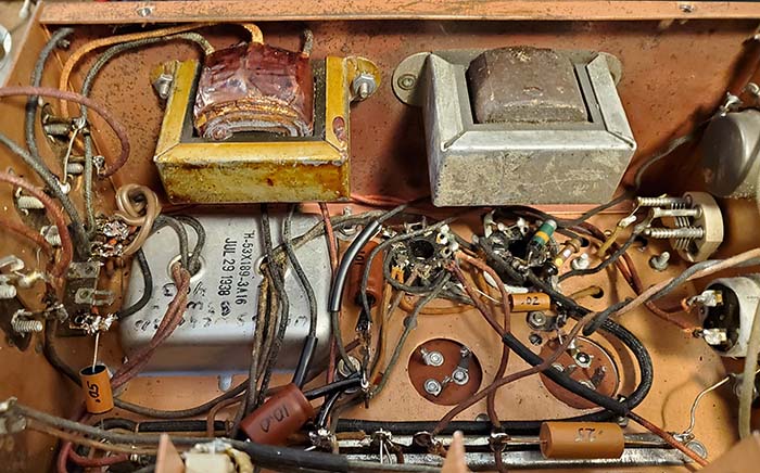
A close-up of the power supply
section of the 450A showing the bottom of the W-G replacement power
transformer and the HRO-60 audio output transformer. I don't
know why the HRO-60 audio transformer is MFP coated, normally
they aren't. This transformer was in a box of HRO-60 spare parts
I was given and had been marked "HRO-60" and it does check-out
as that. Works great! |
June 19, 2024
- Three electrolytic filter capacitors are required to replace the
single 8uf and the dual 8uf capacitors.
I'm not going to remove the can filters but they will be
disconnected. Under the chassis I'll install three 10uf 450vdc for
the 8uf electrolytic capacitors. Modern electrolytics are very familiar-looking so I've painted the
replacements maroon so they won't "stand-out" as much.
Finished all of the polyfilm capacitor installation. I installed
one of the 10uf electrolytics. One lead on the filter choke
needed an extension added. All that remains will be to install
to two remaining 10uf electrolytics and then install a suitable
AC power cord (I found a vintage cord with a molded plug that
should look original.) June
20, 2024 - Installed the two remaining
electrolytic capacitors. Installed the vintage AC power cord.
Tested the tubes and found that one of the 6V6 tubes was much
lower gm that the other 6V6. The low 6V6 was just barely above
minimum acceptable, so it was replaced. One of the 6J7 tubes
tested at minimum acceptable so it was replaced. All other tubes
tested good. Found some replacement tubes for the 6V6 and the
6J7(replaced with a 6J7GT.) Cleaned tube sockets with DeOxit and
installed the tubes.
AC Applied - To power up the 450A, I monitored the input
voltage
to the Candohm resistor which is also the 6V6 plate voltage. I
slowly ramped up the Variac and stopped at 90vac input. The
receiver took
a while warming up (at that low of an AC input voltage) but I finally heard some noise in the loudspeaker. The 6V6 plate
voltage was +210vdc. I increased the AC input voltage to 115vac
and the 6V6 plate voltage was at +255vdc which was perfect. I
had the receiver on the AM-BC band with a ten foot long test
antenna. I adjusted the RF Gain and AF Gain controls and tuned
(no dial mounted yet) by looking at the tuning condenser mesh.
Several of the Reno AM-BC stations "pounded in" quite strong.
KKOH 780kc had the R-meter about mid-scale. Lots audio power
available. Tried a few other stations and all sounded fine. I
switched the AVC on and off and some distortion could be heard
with the AVC off which isn't unexpected. So far, the 450A seems
to be functioning fine but I'll have to install the glass dial
and points before I do any alignment. Also, I have to do further
testing on shortwave with a large antenna array to see how the
higher frequencies are operating. Also, the BFO needs to be
aligned. But, for a first test, this was a good one. I'm sure
this is the first time that this Howard 450A has been functional
in several decades. |
| Further Testing
and 465kc and 1560kc IF Alignment - June 22, 2024
- Although the 450A pulled in signals quite well on AM-BC,
that's not particularly difficult for almost any
receiver,...even a crystal set. Further testing at higher
frequencies resulted in no reception of anything on shortwave. I
connected up an outdoor wire antenna and I did manage to hear
15mc WWV but nothing else. Since 15mc WWV was tuned at about
16.5mc it was apparent that the first thing required would be to
get the IF in alignment. The 465kc IF trimmers are located on
the top of the IF shielded box. The trimmers were so far out of
adjustment that I had
to inject a 465kc signal into the grid of the second IF and peak
that transformer. Then move the signal injection to the grid of
first IF and peak that transformer. Finally, a signal was
injected at the Mixer grid and the remaining IF transformers
peaked. The trimmers were way, way, way off. Nothing was getting
through unless the signal was tremendously strong. Also, when
adjusting the 465kc IF, the switch has to be in SHARP so that
all of the transformers are being used. Of course, the crystal
was given the sweep treatment to find out exactly its resonant
frequency for the final IF adjustment. The 1560kc IF is adjusted
using the trimmers that are on the lower side of the IF shielded
box. The 1560kc IF was
moderately off, not anything like how far off the 465kc IF was,
but adjusting the 1560kc trimmers did improve that IF section's
response. When switching back to the lower frequencies and the
465kc IF, the improvement was unbelievable. Signals on 20M were
pouring in (well, it was Field Day) and after a little adjusting
of the BFO, the SSB signals demodulated pretty well. RF gain had
to be reduced a lot which not unexpected. WWV 15mc was now very
close to the 15mc index mark (that's how far off the IF was!)
WWV 10mc was very close. Nothing heard on 40M. I had to DeOxit
the AVC switch to get it to work and that got the R Meter also
working correctly on AM signals. |
RF Tracking Alignment
- A few unusual things in the 450A RF section. The component
assembly drawing shows tubular trimmer capacitors but this receiver has
vertical sliding plate trimmers. Each LO band has a trimmer and
a padder. This allows adjusting both the upper end of the dial
and the lower end of the dial for very accurate tracking (the
exception is a padder isn't provided on Band F.) Access to the padders
requires a right-angle blade tool. A blade screwdriver can be
used with some difficulty. Band A (AM-BC) was quite a bit off.
Band B was also off. Band C and Band D were very close to tracking
correctly and only needed a slight adjustment. Band E requires
the 1560kc IF but the RF tracking adjusted fine. Band F (up to
60mc) had to use a harmonic of 30mc but alignment was okay.
Complete IF and RF alignment was required and allowed this 450A
to now receive signals on all bands.
Reassembly - June 23, 2024 -
The front panel is secured to the chassis vertical rails by
three screws on each side. Control that are mounted to the
chassis aren't mounted to the front panel but the Phone Jack,
the AVC toggle switch, the BFO frequency selector toggle switch,
the Send-Receive switch, the Tone control and the BFO-on/injection
control are all mounted to the front panel. The knobs were then
cleaned and installed. The receiver was now ready to install
into the cabinet. The front panel is screw-mounted to the
cabinet. The chassis mounting screws were missing so
replacements were installed. There's no lid on the cabinet but
there is a "flip-up" panel on the back of the cabinet that allow
access to the tubes,...barely. The bottom cover over the RF
coils was missing. I'm not sure of the material. Some receivers
had heavy cardboard covers but if it was metal it would probably
have been mild steel and probably thin, like 22 gauge. I'll have
to make a cover. |
| Performance
- I first tested the 450A using a 50' end-fed wire antenna.
Performance was okay but due to wide impedance variations, 40M
reception was way down while 20M was pretty good. I moved the receiver
into the ham shack so I hook up the Collinear Array antenna. 40M
perked right up with a matched antenna. 20M was very active with
signals. This was about 3:30PM in June, so 80M was dead. I tried
Band E and switched the IF to 1560kc but nothing was heard. I'll
try some test signals from the HP606B RF Signal Generator. When
doing the alignment, all bands received signals. The 450A
sensitivity is decent and typical of late-thirties design. The
dual IF concept might have looked good on paper but it
complicates the circuitry and quantity of components with little
benefit. The Crystal Filter works quite well. The entire
receiver seems a bit "flimsy" in construction although it might
only be in the RF front end that's using lead-supported
coils and those leads are going directly to the band switch tabs (asking
for stability problems?) There's a lot of wear in the RF gain control
but if adjusted carefully it's okay. The TONE control pot might
be defective since it really doesn't do anything (typical RC
Tone circuit.) The R-meter
works fine. Overall, for a little over $100 in 1938, the
Howard 450A was probably a bargain and undoubtedly performed
much, much better back then when there were 85 less years of
wear and tear along with endless "diddling and heavy-handed repairs." I tried
to put the 450A back to as close to original as I could but
there's just too much that's been ruined by careless
rework in the past. I certainly believe that when it was new,
the Model 450A was a spectacular receiver that performed
admirably. If I had a 450A "parts set" that could provide
replacements for the many "ruined assemblies" I think this 450A
would become quite a nice receiver.
As it is now, it's a very good receiver with a few minor issues.
More on the DOWNSIDE - The
Howard Suggested Band Spread Mod - Listed in the notes for
alignment in the Rider's PTM information (from Howard) is the
suggestion to remove one rotor plate and the stops from each
section in the band spread condenser to increase the spread,
that is, to have very little change in frequency per BS knob
revolution. It's really,...and I mean REALLY TOO BAD that
someone in the past believed the Howard hint and did remove one plate
and stop on each the band
spread rotors. This has made the band
spread virtually useless with endless knob turning for very little
frequency change. I've found what works okay is to leave the BS
on 500 and just tune in stations using the Main Tuning and then
only use the BS for a vernier F control. It really doesn't affect the calibration much
since from BS tuning from 1000 down to 0 must only change the frequency about 30kc
if on 40M and maybe 70kc on 20M band (BS has very little effect on 80M.) The Howard mod
RUINS the BS function, in
my opinion. No quality repair is possible unless an original, unmodified BS condenser
could be salvaged from a "parts set" (since the rotor plates and
the stops are long gone on mine.) Finding such a "parts set"
would take miracle.
|

1938 Howard Model 450A Receiver
Hopefully the stunning bench
presence with the dazzling array of whirling needles and
tell-tale indicators made up for the more-or-less average
performance. Certainly, the new owner/operator was, with a
little practice, able to soon discover that his new (but slightly idiocentric)
receiver really was capable of providing decent performance. |
| Ant/RF Coil
Impedance on Bands B and C - Although during alignment Bands B and C seemed to work, when
connected to an antenna, the gain is noticeably down. I did use
the HP606B to provide a marker signal to confirm this lack of
gain. Since I was receiving the 606B via the antenna, I thought
that maybe there was a burned primary on the antenna coil
(common problem.) I used a clip-lead to connect the antenna
directly to the RF Amplifier grid and bypass the primary. I
retuned the antenna and signals jumped out. I disconnected the
clip-lead and went back with the antenna connected through the
primary. I noticed signals were still present and strong. The
antenna tuner tuned radically different than normal for the
frequency and retuning makes the
difference between signal reception and not receiving much of
anything. I used the standard
dummy antenna loads when doing the alignment but not the Howard
dummy antenna,...maybe that might account for the big change in
matching impedance. The other approach might be to align the
Antenna coils/RF Amp trimmers with the Antenna Tuner already
matched and then tune the 450A trimmers for maximum background
noise on the desired frequency. The Howard dummy antenna was the
standard using a choke, a capacitor and a resistor with an
additional .05uf coupling cap for IF alignments. I just used a
200pf on Band A and B and then a 300Ω for Bands C-F. With
the HP606B pumping a signal into a ten foot long test wire
located in the next room, I had a signal at the 450A that was being received
through the antenna. I found that on Band C the Ant/RF coil was
quite a bit off. I set the 606B to 6.0mc, did the same with the
450A and then adjusted the coil trimmer for max signal. I went
to 4.0mc on both units and then found the the Antenna Tuner did
resonate very closely to the normal settings for 4mc. On Band B,
I only used the center conductor since the tuner won't go any
lower than 3.5mc. I did the set up at 2.8mc and found that while
the Ant/RF trimmer was fairly close, for some reason I had the
Mixer trimmer pretty far off. Test signals received okay on Band
B. So, just minor adjustment problems. It's hard to say whether it all
would have been avoided if I had used the Howard Dummy Antenna.
Maybe. The only other place I've seen the RLC Dummy Antenna is
in military manuals on some equipment. Most thirties and forties commercial gear
alignments use 200pf for MW and 300Ω for SW. It assumes that
the antenna to be used will generally be short for MW use but
will be good for SW and the receiver's antenna input Z is 300Ω.
UPDATE: July 1, 2024
- Listening on the 20M band about 1400hrs PDT. Using the Band
Spread as a freq. vernier works pretty well for tuning in SSB
signals. Went up to just over 15mc WWV and thought I heard a SSB
signal,...and I did. It was Trenton Military on 15.035mc USB
with the Aviation Weather out of Trenton, Ontario, Canada. This
is a pretty easy station during the winter but fairly difficult
during the summer. Trenton was Q5 and S6. The Howard 450A takes
a little getting used to and I've noticed that the more I use it,...the
better it performs (or the more I get used to its idiosyncrasies.)
NOTE: July 5, 2024
- The Howard 450A is going to return to the workbench next
month. I've ordered a special "long shaft" 5K 2W potentiometer
with switch to replace the worn-out RF Gain control. Also, I'm
planning on repairing the Band Spread condenser by adding the
missing rotor plates back to the air variable. I'm going to
search through the junk boxes and find an air variable with
about the right size rotor plates and see if I can remove them.
Early style (from the 1920s) air variables could be disassembled to remove the
rotor plates and that might be how I accomplish getting three
rotor plates. I'm sure I'll have to trim and size the rotor
plates to match as closely as possible. How to successfully mount
them so they are secure and still making contact with the
grounded rotor shaft will have to be something I'll experiment
with. Other work planned is to revisit the 1560kc IF alignment
and the 1560kc BFO adjustment. Neither seems to work very well
although they seemed to align fine. Also, I want to recheck the
Tone control functionality. The 450A is a pretty good
receiver and I think with a little more rework, I can get it to
approach a "very good performer."
Aug 1, 2024: 450A Back on the Bench
- The first bit of work was to install the new 5K 2W pot with AC
power switch. I got this part from Greece because I needed a
"long shaft" and the AC power switch and these options combined
with a rather low resistance of 5K seemed to be difficult to
find from a USA supplier. I never thought about the part
actually being "made in Europe" until I started the installation
and discovered that the standard USA mounting nuts didn't fit.
Luckily, the pot was supplied with one mating nut, so I just
found a larger diameter nut to act as a spacer. I had to just
slightly enlarge the mounting hole in the chassis. A few passes
with a fine file allowed the pot hub to fit through the mounting
hole. The standard USA
lock washer did fit but just barely. Also, the pot shaft had to
be cut down from 4" long to about 2" long and that was easily
accomplished. Then the pot was mounted and wired. Testing went
fine with no problems. Now the RF Gain shaft doesn't wobble
around and feels nice and tight. Operation is as it should be.
Next is the Tone control that doesn't seem to do anything.
There's nothing wrong with the pot. The problem is the very low
value of the C in the RC. It's only .01uf so the change in tonal
response is barely noticeable. I clip-lead connected an
additional .033uf and then the Tone control made a nice change
to the audio response. I replaced the .01uf with a .05uf (the
test had .043uf so .05uf is close enough.) Lots of range in the
TONE adjustment now.
The 1560kc IF,...IF was way off. I thought I had aligned it to
1560kc but apparently not. The IF was so far off, I realigned
the front end on Bands E and F just to make sure everything was
on frequency. Although the noise floor came up significantly, a
substantial antenna is required for much in the way of signal
reception on Bands E and F.
In looking closely at the band spread condenser I was surprised
to find
that the rotor plates are "glued" in place on the rotor
shaft. At first, the glue looked like old Duco cement but it's as hard
as epoxy and it doesn't want to chip off. The epoxy would have
to be removed because it was smeared over and into the rotor
shaft grooves that the rotor plates would mount to. Whatever
this glue is, it's permanently part of the rotor shaft now. This glue has all but
eliminated the possibility of replacing the missing rotor
plates. At first I thought about adding a second stator plate
but further thought and I knew that would only increase the
static C value and there would still only be one rotor plate
varying the capacitance, so
the end result would be about the same band spread effect.
Unless an original 450A (or 450 or 440 models) band spread condenser turns up, I guess
I'll be stuck with this destructive mod.
That completes the rebuild on the 450A. It's a nice performing
receiver with commanding bench presence but I wish the band spread hadn't been ruined. |
|
The Hallicrafters,
Inc. - SX-9
- Contractor: Howard Radio Company
Bill Halligan made several
deals with Silver-Marshall Mfg. to start The Hallicrafters, Inc. and began offering receivers in 1933 with the first receiver designs
using TRF circuits. Halligan didn't have the necessary licenses to build the
radios and sold his early radios by mail order to avoid potential RCA lawsuits. S-M also didn't have the RCA license
for Superheterodynes (or TRFs.) Since
neither S-M nor Halligan had the necessary RCA licenses all legal
radio building had to be performed by Howard Radio Company (who did have all
of the
radio licenses.) Howard had moved into the Silver plant after he purchased
his company back from Everett Piano Company in 1934 and moved his company
back to Chicago. RCA had sued McMurdo Silver for
building radios without the RCA license so the move of Howard into the
Silver plant solved several problems for all involved. Howard Radio is the most likely contractor for the
SX-9 since the early Hallicrafters receivers involved Silver-Marshall and
McMurdo Silver. Howard Radio built the Hallicrafters receivers up through
the 5-T and the SX-9. By August 1936, Halligan had made his arrangements with Case and
had purchased Echophone. Since all of
the early Hallicrafters receivers seem to have been built at the
Silver-Marshall plant and Howard Radio was the actual RCA-licensed company
building radios there, the SX-9 was almost certainly built by Howard Radio.
In fact, on this SX-9, the paper tag is still on the chassis that has
"Manufacturer No. 1731" indicating Howard Radio Company as the builder. The
SX-9 was offered in late-1935 through early-1936 and featured a built-in speaker, nine
metal-type tubes and Aladdin iron-core IF transformers in a superheterodyne circuit with
bandspread. The first Hallicrafters receivers built without a contractor
were the SX-10 and SX-11. The SX-9 was a significant
improvement over earlier TRF models that Hallicrafters had been selling. Its
performance is usually rated quite good, even though it still retained a somewhat crude
"amateur" appearance.
|
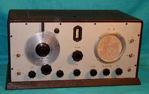
The Hallicrafters SX-9 was their last
contractor-built receiver although early 5-T Sky-Buddy radios
were also contractor-built. |
| Acquisition - Many years ago,
in the mid-1990s, the
Sierra Nevada Amateur Radio Society (SNARS) held their then
annual August swap meets at the Stead Airport north of Reno. Old
friends NU6AM, K6DGH and KØEOO used to come up for the swap
meet on Friday afternoon and would stay overnight at the Gold Hill Hotel just over the Divide
from Virginia City. Usually a Friday afternoon visit to the WHRM
was part of their trip. On one of their "pre-swap meet" visits,
Peter K6DGH saw a Meissner Signal Shifter that I had. Now this
wasn't just any old common WWII Signal Shifter. It was a
pre-WWII very early all black wrinkle panel with glass covered
airplane dial Signal Shifter and it had a separate power supply.
It was the only early Signal Shifter like that I'd ever
seen (then and since.) Peter "had to have it" to go with his Hallicrafters HT-4 transmitter and offered a particularly
generous trade,...a nice condition Hallicrafters SX-9. After
seeing the SX-9 that Peter had brought along to sell at the
Stead Swap Meet, I agreed to the trade.
I didn't do anything to the SX-9. I didn't even test the
tubes. I put it on display in the museum and it stayed there
until we closed in 2012. Since then, the SX-9 has been stored in
the shop on
a top shelf in my climate-controlled room (well, the temp only
varies from 75F down to maybe 20F and there's absolutely no
light unless the overhead lights are turned on.) I did
"touch-up" the bottom raised platform where the wrinkle finish
paint had flaked off before I put it on display but, other than
that, nothing has been done to this receiver in the 25 years
I've owned it. So,...I guess it's about time I find out just how good of
a receiver the Hallicrafters SX-9 receiver is and, additionally,
a close examination maybe provide some clues as to the
contractor's identity (Howard Radio Company is the suspected
contractor.) |
Circuit - The
SX-9 uses all metal-octal tubes, specifically a 6K7 RF amplifier, a 6L7 Mixer, a 6C5 HFO, a 6K7 IF
amplifier, a 6H6 detector and AVC, a 6K7 BFO, a 6F5 1st audio
amplifier, a 6F6 audio output and a 5Z4 rectifier. Eight
tubes are used in a single preselection, single conversion
superheterodyne circuit using one stage of IF amplification. "SX"
denoted that a Crystal Filter was installed in the IF that
operated at 465kc. The rectifier accounts for the ninth tube.
The SX-9 was advertised as using ALL metal-octal tubes and was
one of the first receivers actually sold with all metal-octal
tubes
(although the Tobe Deutschmann "TOBE Special" receiver, also from
1935-36, used all metal-octal tubes but it was a ham
receiver kit.) The use of the 6H6 duplex-diode and the 6F5
triode as "separate tubes" rather than using the duplex
diode-triode 6Q7 was an unusual choice, something like what
Zenith Radio was doing in some of their consumer radios to
"increase the tube count."
But, designs for Hallicrafters were certainly in a state of
constant and rapid change at the time since Howard Radio was
building the radios at Silver-Marshall/McMurdo Silver. By
the SX-10 and SX-11, with Hallicrafters now doing their own
assembly, the designs become more
conventional and follow the typical single preselection with two
IF amplifiers, duplex diode-triode detector/AVC/1st Audio and
then Push-Pull audio output with external loudspeaker receivers
that had become the "standard ham receiver" of the time. |
| Getting Started
- As I mentioned, in the 25 years that I've owned this SX-9 I've never even taken the chassis out of
the cabinet to have a look underneath. What
I find there will be "all new" to me.
June 25, 2024 -
Brought the SX-9 in from the shop. I pulled it out of the
cabinet and found that, except for the two filter capacitors and
one obvious Black Beauty cap, it was all original underneath.
The filter capacitor were probably replaced decades ago (date
code from 1949.) These were top quality bakelite sealed caps so
I tested them and they seemed to be okay. I thought I'd try the
SX-9 "as is."
The "Mostly Original Parts"
Challenge - In checking all of the major
components and finding that everything is okay. First problem
was with the power cord. It had one side open so no AC to the
power transformer. I clip-lead connected a test AC cord in place
and then slowly ramped up the AC input voltage. Just the band
spread dial lamp illuminated. Nothing heard, no even a slight
hum. Well, not unexpected. I'll have to do the usual inspection
and test to see what I come up with. On closer examination, like
looking at the schematic, I saw the the audio is completely
cut-off if the bias cell is gone (or open like this one.) To
avoid damaging the cell (since it wasn't necessary) I made up a
-1.5vdc cell from a Energizer #357 and soldered it to the
terminals. Now I had some hum in the speaker but no signals. I
connected up the HP606B and input a signal at 2.0mc and I could
just hear and could tune in and out of resonance the signal,
indicated that it is possible to "ram a signal through" but
that's all. I checked all B+ voltages, plates and screens and
everything looked okay (probably those replacement filter caps
were a major factor.) Weak Tubes and Weird Bias
Cell Hook-up - I tested all of the tubes just to
see where that would lead. The 6L7 Mixer tube barely moved the
TV-7 meter. The 6C5 LO was about 50% below minimum acceptable.
The 6F5 1st AF Amp barely moved the meter. The three 6K7 tubes
all measured exactly at minimum acceptable (okay to use but not
like new.) Only the 6F6, the 5Z4 and the 6H6 tested as good
quality tubes.
With all tested-good tubes installed, the SX-9 still didn't
function much. The bias cell is in series with the audio signal
which seems like an odd way to achieve the -1.5vdc grid bias,
but it does work. Audio injected at the 6F6 grid sounds fine,
not so at the 6F5 grid. If 465kc is injected at the IF grid or
the Mixer grid, only a pulse of a signal is heard and then it
drops off. A 2.0mc signal at the antenna will produce a weak
signal.
|
Repair versus Restoration?
- It seems obvious that this SX-9 has several defective
capacitors. But, repairing a set to just "get it to work" is really only a
temporary fix. This SX-9 is going to have to be restored. There
are other issues that can then be taken care of, such as the severely bent
front panel that's going to require panel removal in order to
straighten it properly. The panel seems to be tempered and
removing the bending is going to be difficult. The band indicator pointer is a
crudely-made repair piece that needs to be redone or replaced. The wire
index behind the band spread dial is totally bent and will
require dismounting to fix. So, lots of mechanical problems with the
SX-9 besides the numerous defective components. Restoration is
the only practical solution.
Inspection - After disassembly, I discovered that
the panel finish was stained and in very poor condition. The more I cleaned
it, the worse it looked. I'm not sure what type of matte finish
was applied but since the silk-screened nomenclature is still
present, I'd assume it's the original finish. There are problems with
some sort of black tar that was used to mount or seal the
loudspeaker to the panel and that has gotten everywhere. It can
be removed with denatured alcohol but it appears to have stained
the panel finish. The plastic Band Spread dial has been damaged
by the black tar and the dial itself is severely warped.
Additionally, all of the small knobs are not original but are
WWII versions that look similar (have hex-socket dual set screws.) The loudspeaker is original and has a special
tapped field coil and a special output transformer. The cone was
damaged in the past and was glued with Duco cement. The speaker
can't be replaced unless another original could be found. I
don't think it can be reconed either since it has a metal upper
spider support for the VC-cone with no lower flex support for
the VC-cone.
Besides the usual restoration problems, the band spead dial
should be replaced, the loudspeaker really needs rebuilding and
I'm sure there are even more problems lurking. The more I look at this
SX-9,...I'm thinking "shelf queen." |
|
The
Hallicrafters, Inc. -
5 -T "SKY-BUDDY"
(1935 "Boy Dial" versions built by Howard
Radio Co.)
Bill Halligan believed there should be a market for an
inexpensive shortwave receiver that would perform well enough to inspire
young enthusiasts to choose "RADIO" as a hobby or as a career. First,
the youngster would become an SWL (Short Wave Listener,) then go on to
become a ham and finally would make RADIO a career. The idea certainly
appealed to the parents of technically talented kids and it was those
parents that were the target market for "entry level receivers."
Halligan's goal was to be able to produce the receiver at a cost low
enough for the Depression-era parents of 1935 to afford the set
for one of their "radio-minded" youngsters. At $29, the 5-T Sky
Buddy certainly wasn't low priced (equivalent to $660 in 2024
dollars.) But with 5 tubes the
performance was adequate to inspire hoards of young users to become
hams. Many hams remember that their first listening experience to
shortwave reception was on an "entry level receiver." (Of course, today
most older hams remember the Sky Buddy's post-WWII successor, the S-38,
as providing their first SW reception. As a kid, my first successful
shortwave listening was on a second-hand "borrowed" S-38B.)
To ensure that the purchasers knew who the intended users of the
5-T Sky Buddy were supposed to be, the first production
receivers included a picture of a "young ham sending with a bug" on
the dial. There was a story that Bill Halligan had a neighbor
that couldn't afford an expensive receiver for his
radio-enthusiast son who happened to have been named Buddy. Supposedly, Halligan built (or
had built) a small receiver for the boy and called it a "Sky
Buddy" - an apocryphal tale? - perhaps - but this was the inspiration for Halligan
and Hallicrafters to offer an inexpensive, entry-level receiver. |
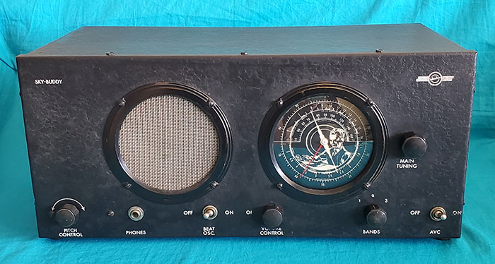
The serial number
stamped on this "Boy Dial" 5-T chassis is 024919. |
|
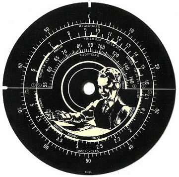
The 5-T "Boy Dial" |
Certainly, the initial "Boy Dial" was meant to inspire young
enthusiasts. A close-up of the dial is shown in the photo to the
left. Note in the close-up of the "boy dial" that the boy is
depicted using a semi-automatic telegraph key (bug) and is
listening using "phones" just like a "pro." Of course, the vest
and tie help for that future job interview to get into
professional RADIO! Even though the 5-T Sky-Buddy is
thought of as a product of Hallicrafters, the first versions built in
1935 (with the
"Boy Dial") were built at the Silver-Marshall-McMurdo Silver
building in Chicago by Howard Radio Company. Many of the assembly and component
characteristics of the "Boy Dial" 5-T are recognizable as a
Howard Radio product. The external-to-the-chassis BFO coil, the
belt-drive tuning along with the dial and speaker bezels and
other construction techniques are very recognizable as
characteristics found in other receivers built by Howard Radio
Company. Another interesting bit of speculation is that McMurdo
Silver designed the 5-T. It's certainly a possibility and
certain design characteristics seem to have basic similarities
to McMurdo's designs (the tapped field coil speaker and the
elaborate belt-drive for such a small radio, for instance.)
The next run of 5-T radios were produced
after Halligan had set-up at the Echophone building and was
producing his own products. The dial mechanism was changed to
eliminate the belt-drive. The "Boy Dial" was also
gone. No doubt, the 5-T was
successful and popular. So popular, in fact, that many adults
were buying the receiver for their own use. When the next run of
Sky Buddy receivers were produced, they were actually built by Hallicrafters
and the new dial had SKY BUDDY in a banner across the center of
the dial. Maybe this was to make the receiver look less like a kid's toy
and more like a serious ham receiver.
The Sky-Buddy continued on with various changes made but the
basic concept of an inexpensive entry-level receiver remained.
Sky-Buddy production was halted as WWII began. When
Hallicrafters entry-level receiver returned after WWII, the
circuit was changed to an AC-DC radio and the receiver was
designated as Model S-38.
|
| Acquisition and
Mechanical Rebuild - This 5-T Sky Buddy was in
the collection of Dave Walker (Walker Electronics) of Reno,
Nevada. Walker had been a Reno radio/electronics repairman for decades
operating in a small converted grocery store on Wilcox St. in
downtown Reno. When Walker retired in about 2016 (at age 84!) he
sold his parts, equipment, benches and junk radios to a collector
friend of mine. The collector friend practically gave the 5-T to
me ($25) because it was in need of so much electronic and
mechanical help. Walker had never done anything to it, which
isn't surprising. Since his job was fixing up radios, it wouldn't
also be his hobby. The 5-T was certainly
in the same condition as he had found it when I obtained it. It was
missing the speaker entirely. The knobs were gone. The tuning
didn't work. The cabinet was bent. On and on. I did the
mechanical rebuild and found a suitable field coil speaker to
replace the missing speaker (the original field coil had a
very high DCR of 3500 ohms.) I took apart the dial to
install a tuning belt. It took a few years but eventually I
found all of the correct hexagonal knobs. The 5-T still is awaiting an
electronic restoration in order to become functional once again. June 29, 2024
- This 5-T project was placed on the "back burner" after I had found the
necessary parts to do the restoration. I know I was trying to
figure a way to build the waxed-cardboard box that held the
electrolytic filter capacitors. The metal multi-section is
pretty obvious as a "hack-job repair attempt." The non-original
WW resistors also need replacements. There weren't too many
paper caps and all were originals, so I had planned on restuffing the paper dielectric capacitor shells. For some
reason, I assembled the receiver and never did the work. I think
I had put the 5-T back together before I had found all of the
correct hex knobs for the receiver. What needs to be done now
isn't really that much to complete the job. First will be a
complete recheck and assessment of the receiver and then proceed
from there.
The photo to the right was taken when I initially got the 5-T.
Obvious is the missing speaker. Besides the high DCR of the
field coil, the replacement speaker also needs to have the audio
output transformer mounted on the speaker. There's no plug on
the speaker cable and it's connected to the chassis by soldering
the wires. |
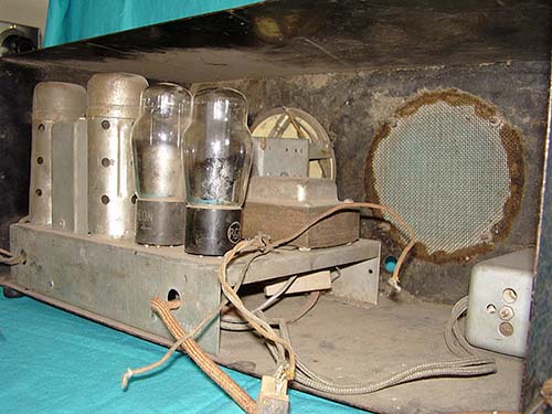 |
|
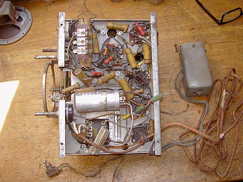
Under the chassis showing
careless repairs. The multi-section electrolytic isn't original.
It should be a cardboard box type of electrolytic. The
ceramic resistor and the two green wire wound resistors aren't
original. |
Inspection - July
2, 2024 - Power transformer tests okay. IF
transformers test okay. The Candohm tests okay. The loudspeaker
isn't the original so it doesn't have the bucking winding. The
field coil is part of the negative B- and is part of the grid
bias used on the 42. This wiring was missing since someone had
tried to use a PM speaker as a replacement years ago. The
speaker I have is a single field coil winding and that will work
as far as the B-. There was a popular trend in the thirties that
believed the field coil presence near the voice coil caused hum
in the VC of the speaker so a bucking winding was added to the
VC connection to "buck" the hum. It's a very slight hum at the
most and the bucking connection wasn't ever used on all field
coil speakers. The audio output transformer on the speaker is
the correct vintage for working with a 42 (it was salvaged from
a Play-Mor radio.) There are 11 paper dielectric capacitors and
two electrolytic filter capacitors used in the 5-T circuit.
Moderate wear, not excessive.
The Plan - In
the past I
had thought about restuffing the original Sprague paper
dielectric capacitors but then I'm looking at the very
non-original loudspeaker that's going to require some
modification to the circuit to function correctly. Also, there's
the
filter capacitor situation. The 5-T will never be original or
even look original upon close inspection. The dial drive system
was missing parts when I got the 5-T but a rubber belt was able
to function without the missing parts. So, I'm thinking about
doing the same thing with the 5-T that I did with the Howard 450A and paint modern polyfilm capacitors Raw Sienna which makes them look vintage.
The electrolytics will be painted maroon to look vintage.
However,...
Reconsidering the Project
- Like before, it's difficult to become inspired by this
particular 5-T example. It would have to be modified from original
because of the missing loudspeaker and the dial tuning using a
rubber belt doesn't work like the original. To have this 5-T
operational wouldn't really reveal anything important. It's a
five-tube receiver of limited performance capabilities. Like the
SX-9, the 5-T looks like it's going to remain a "shelf queen."
I'm going to reassemble it and consider that it's a decent
example of the 5-T but not an original one.
|
|