Radio Boulevard
Western Historic Radio Museum


Hammarlund Mfg. Co., Inc.

SP-600-VLF
MW-LF-VLF Receiver - 540kc to 10kc

Circuit Details, Comparison to HF SP-600, General Performance Features
Details on the Almost Useless Manual and the Obtuse Alignment Procedure
How to Fix the Slipping Tuning Dial (works for the HF SP-600 versions, too)
630M Operation, 630M Beacons, 2022-23 NDB SP-600-VLF Log
2024 Workbench Visit with details on the Turret Disassembly and the 24 RF Coil Assemblies
An Easy RF-IF Alignment Procedure that Works, Includes Sweep IF Alignment Details & Photos

by: Henry Rogers WA7YBS


HAMMARLUND MODEL SP-600-VLF

This article is a compilation that features an ALL NEW 2024 write-up that details the front-end disassembly and RF-IF alignment of the SP-600-VLF. The object of the new RF-IF alignment was proving that the Hammarlund manual's "impossible to perform" alignment procedure was NEVER used by commercial technicians (it probably wasn't even used by Hammarlund) and that the receiver can (and should) be aligned using conventional RF-IF alignment techniques that includes a standard sweep alignment of the IF section. The new 2024 section has a complete procedure with photos for sweep aligning the SP-600-VLF IF section and instructions for the RF Tracking alignment. The other sections of this write-up are a complete re-editing of various SP-600-VLF paragraphs and notes that I've been writing over the past ten years. After using this SP-600-VLF for a decade, I have to say, all things considered, it's the best of the vintage tube-type LW receivers that I've tested and operated. I've used it for 2X QSOs on 630M with ham stations out to Pennsylvania and have logged hundreds of NDBs from all over North America. World-wide PE-PM time signal stations, USN Sub-Fleet Comm stations and a multitude of other LW signals have been received with this SP-600-VLF. Well-maintained "600-VLFs" are fairly easy to work on if necessary, they're dependable, very sensitive and they really do work well for 630M operations and, actually, just about any signal reception below 500kc, provided the proper type of antenna is used,...and your QTH is in an EMI/RFI quiet location.
 

Hammarlund Mfg. Co., Inc. - SP-600-VLF MW,LF and VLF Receiver


1958 SP-600-VLF31 sn: 20101, in a Hammarlund 600 Series Table Cabinet

General Information - When the first paragraph of the SP-600-VLF31 manual states that the receiver is unique because the tuning "extends to audio frequency 10kc" one wonders whether the writer of the manual understood the difference between 10kc of varying air pressure (sound-audio) and 10kc of radio frequency oscillation (a varying electromagnetic field.) Of course, the writer was probably thinking of a RMS voltage varying at 10kc (more on the Hammarlund VLF manual's "problems" further down this write-up.) The SP-600-VLF is not a "converted" standard SP-600 HF version (high frequency, the typical .5-50mc SP-600 receiver.) Although it uses a lot of the same mechanical designs as its HF brother, the 600-VLF is a very different, special design receiver. It's a single conversion, double pre-selection superheterodyne with six tuning ranges covering 540kc down to 10kc. It uses 705kc for its IF. The SP-600-VLF was designed specifically for MW, LF and VLF reception.

The SP-600-VLF31 was first offered in 1954. It was the first VLF version of any Hammarlund Super Pro and the first VLF receiver of the SP-600 series with a later SP-600-VLF38 for 25 to 60~ AC operation being the only other version produced. The SP-600-VLF31 receiver featured in this write-up is Serial Number: 20101 from 1958 (latest date code found.)

Hammarlund also produced several SP-600-VLF receivers for the Dero Research and Development Corporation. These receivers are identical to the SP-600-VLF31 except they'll have "Dero Research and Development Corp." with "Model 2F VLF Receiver" engraved on the front panel and there's a small metal etched data plate tag with the Dero name mounted below the Audio Gain control. The Dero example I saw didn't have the Hammarlund data plate mounted on the tuning condenser cover but whether that's normal for all Dero receivers is unknown. See Dero 2F photo below from the Hammarlund Historian website (although it did require a lot of photo-shop editing to straighten the photo and get it looking decent.)

Long Wave Reception Then and Now - The 1950s was a time when the radio frequency spectrum below 500kc only had to contend with atmospheric QRN. There was very little "wide-spread" man-made RFI except close to highly industrialized areas. Long wave was brimming with signals that included many voice transmissions and lots of true CW transmissions. Even though all Long Wave Broadcasting came from Europe or Asia, their stations ran high power to large antenna arrays so it wasn't too difficult to receive their signals here in the USA. Other signals were from the many Coastal Stations that handled ship to shore traffic. Most of these signals were in the CW mode but, if you could copy Morse, the messages weren't encoded so it was interesting to "listen in." At the time, the USN Stations also sent CW from some stations and though encoded it did provide some interesting code practice. Navigation and weather stations were abundant. If you had RTTY capability, many regional weather reports were sent via long wave radio stations in standard BAUDOT at 60wpm. Airport Beacons and Airway Range Stations were still operating in the 1950s. There were multitudes of Non-directional Beacons everywhere and many of the NDBs provided Voice Aviation Weather reports.

Unfortunately, over the past seven decades, long wave has changed into today's almost entirely data-driven transmissions that defy decoding, unidentifiable signals of all varieties, virtually no long wave broadcasting, diminishing numbers of NDB stations and rampant RFI from a multitude of urban domestic devices that always seems to be increasing in sheer quantity and in the amount of RFI produced.

In the 1950s, the SP-600-VLF31 would have been used in the laboratory, maybe in commercial coastal stations, in commercial frequency monitoring facilities or possibly some shore-based radio navigation uses. It was an expensive receiver that almost certainly, due to that expense, wouldn't have interested the average radio amateur or the average radio listener (although many "transoceanic-type portables" did include a Long Wave band.") The SP-600-VLF was intended for laboratory and commercial or possibly military users.


The DERO Research and Development Corp. Model 2F version of the SP-600-VLF - photo Hammarlund Historian


I discovered ten years later that the chassis spots were easily removed using WD-40 (2014 photo, see 2024 photos further down.)

Physical Comparison to the High Frequency SP-600s - One notices that the receiver obviously looks like a Hammarlund SP-600JX on the exterior but with several minor physical differences. First, the chassis and most of the sheet metal is gold Iridite finish (a chemical dye for aluminum.) Also apparent are the quite different side panels used on the VLF with square sides, similar to R-390A panels, rather than the pylons used on the anodized aluminum side panels of the High Frequency (HF) SP-600. Another difference is the "X" option that is on the HF 600 has six positions and uses HC-6 crystals but the VLF has only four positions and uses FT-243 crystals. The Carrier Level meter is only a single scale, bakelite case unit reading "db over 50uV" while the HF 600 meter is usually a metal-cased, dual scale unit. With the dual scale meter, a switch for RF-AF is on the HF SP-600 and that's not necessary for the VLF. A "warning" tag (not to use 6kc bandwidth on VLF) is mounted between the tuning dial and the logging dial. There are two additional IF cans that are smaller than the standard IF cans that are for the Amplified AVC and for the Diode Load (Driver) output. The "X" option oscillator uses a miniature tube rather than a metal octal tube used in the HF SP-600JX. The twin-ax Antenna input is not used on the RF platform as on the HF version but a cable is routed out of the RF Platform to standard screw terminals mounted on a rear bracket.

Note on this VLF receiver that a top cover is missing. It appears that the cover was a right-angle bent aluminum sheet metal piece that would engage into the front "pinching" two-piece retaining slot and then, resting on top of the side panels angled lip edges, drop over the side panels vertical lip edges. At the vertical rear panel, screws were used to mount the top cover to the back rails. The cover would be easy to replicate except that it's not shown in the manual. One can guess that some sort of venting was provided but without a picture, exactly how the top looked is really an unknown. Since I have my SP-600-VLF installed in a Hammarlund SP-600 table cabinet that's providing the necessary protection, a top cover isn't really required. 

The SP-600-VLF Circuit - The SP-600-VLF31 is not a HF SP-600 with LF coils in the turret. It's a very different receiver. First, it's not a double conversion receiver (like the HF version) but it is double preselection in that two RF amplifiers are used on all bands. The frequency coverage is from 540kc down to 10kc in six bands. 21 tubes are used in the circuit (20 tubes are used in the HF version.) The IF is 705kc and dual crystal filters are used for passband selectivity. One crystal filter is ahead of the first IF amplifier acts as a 705kc bandpass filter (crystal controlled center frequency.) The second crystal filter is ahead of the second IF amplifier and is a conventional 705kc crystal filter with a phasing control although it operates quite differently than a typical crystal filter (180º rotation for maximum to minimum bandwidth within the SELECTIVITY position employed.) Five different IF bandwidths are available and all SELECTIVITY positions utilize both crystal filters (the HF version uses three of the six positions for its conventional crystal filter.) There is a 1160kc crystal oscillator circuit in the receiver but this is to heterodyne with the 705kc IF to provide a fixed 455kc IF OUTPUT to drive RTTY devices or other types of equipment that require a 455kc input signal derived from the last IF amplifier stage (full selectivity.) Two tubes are required just for this 455kc conversion (6C4 xtal osc. and 6BE6 mixer.) The audio output uses a 600Z ohm transformer that's very similar to the HF version. Amplified AVC is provided as is a BFO and there is a Noise Limiter circuit (LIM.) When selecting CW with AVC, a large value tc capacitor (.25uf) is switched in the slow the AVC recovery for better CW reception. As expected for the vintage, the 600-VLF uses a standard envelope detector circuit so, for CW reception, the RF Gain should be reduced for proper signal to BFO injection ratio and the AVC should be off but it can be used to limit maximum sensitivity if desired. The manual instructs the user to operate with RF Gain at maximum, AVC and BFO on to receive CW signals. This might have worked in the laboratory in the 1950s but not today when connected to an antenna and trying to receive signals with modern RFI noise levels. The "X" function provides four crystal channels using FT-243 type crystals. This "X" function provided a crystal controlled oscillator in place of the LO for f stability.

With two RF amplifers and four IF amplifiers provided, the SP-600-VLF has a lot of sensitivity and a lot of gain,...but does that really help in today's noisy LF region of the spectrum? If the user is inexperienced with the LF spectrum and how to set up a high-performance receiver to operate successfully below 500kc, disappointment is sure to follow. Using a remotely-tuned loop or shielded magnetic loop will be a necessity on MW no matter where the receiver is operating from. Wire antennas can be used in the LF and VLF regions but a low noise antenna is going to be required on MW for successful DX reception. The antenna input impedance is 72Ω.


Underneath the chassis this SP-600-VLF is very clean and in excellent condition. Note that most of the capacitors are ceramic disks on this 1958-built SP-600-VLF  (2014 photo)

SP-600-VLF Performance, Antennas and Some of the Receivable Long Wave Signals

SP-600-VLF Performance - Noise versus Gain - While the SP-600-VLF manual instructs that normal operation for CW reception has the RF GAIN at maximum with the AVC turned ON, allowing the AVC to control the sensitivity, the receiver really can't be operated that way. With today's high noise levels, often the AVC is responding to the noise and not the signals. EMI and RFI Noise is THE problem, whether man-made or atmospheric. Nowadays, the majority of LW signals we search for, whether they're DX NDBs or 630M hams, are going to be very weak signals that are generally "in the noise." For CW, most reception will require the RF GAIN reduced significantly and the AVC turned off and signals received on a loop antenna. There are a few strong signals that can be used for testing. At my QTH, Master Station 'M' Loran-E running 400KW on 100kc located in Fallon, Nevada is just 50 miles away (now that's a STRONG LF signal!) However, the MAJORITY of interesting LW signals will be right in the noise. Certainly the number of times that the SP-600-VLF31 receiver will be tuned to a strong Voice modulated carrier signal, with AVC on and the BFO off, will be very limited. It hasn't happened here in the ten years I've been using the SP-600-VLF. AM BC at 540kc and public information BC at 530kc will be about the only AM voice signals easily received nowadays (although I can tune in a BC station on 540kc it has always been a very weak signal here in Dayton Valley and the 530kc public service info BC from Carson City has gone silent,...the carrier is still on but there's no audio. But, the 530kc CC public service info transmitter only runs 10 watts to a very small antenna, so the signal has always been very weak out here in Dayton Valley.)

Receiver Setup - Nearly all operation of the SP-600-VLF will be with the RF GAIN throttled back to 5 or 6, AUDIO GAIN at about 3 to 5, with the AVC turned off and the BFO on (I've started having the AVC on in an effort to help reduce "pops and crashes" - it helps a little bit is all.) I've found that SELECTIVITY at 1.3kc usually gives the best signal to noise ratio. The XTAL PHASING can be set for narrowest bandwidth (about 1 or 2 on the dial scale.) With high noise it's sometimes better to reduce the SELECTIVITY to the narrowest bandwidth (0.6kc) while keeping the XTAL PHASING at about 2 or so (I've correctly set my XTAL PHASING scale to be the widest bandwidth at 10 and the narrowest at 1.) A 600Z ohm headset connected to the 600 Z ohm audio output (not the phone jack) gives the best results for weak signal detection. The Noise Limiter (LIM) and AVC circuits are not very effective on static bursts or electrical "pops" so keeping the 'phones in front of the ears is necessary during these types of conditions when the 'phones are connected directly to the 600Z output.


The unique, Iridite-finished side panels of the SP-600-VLF  2014 photo
 

Antennas - My first serious listening session was using my 80M Inverted Vee antenna with the feed line shorted. I logged two newly-heard NDB stations. Not that they were any great DX, being PND 356kc in Portland, OR and BF 362kc in Seattle, WA, but they were new ones (#259 and #260, respectively.) I quickly switched to a homemade remotely tuned loop that was six foot diagonally. In Nov 2019, I went to a shielded magnetic loop, the Pixel Loop. The impedance of the Pixel Loop is 75Z which is a good match for the SP-600-VLF's 72Z input impedance. The Pixel Loop was a significant improvement in signal to noise ratio and with ease of operation (the remotely tuned loop had to be "tuned" every few kilocycles,...often, in other words.) As mentioned, weak signal reception on MW is very much improved using a loop antenna. However, on LF and VLF, when using a long end-fed wire antenna, sometimes it's advantageous to have an inline switchable attenuator between the antenna and the receiver. This allows reducing intense signals (not that common) but it also allows finding the best response between the large antenna and the noise generated by everything that the large antenna responds to. I use a switchable attenuator that can reduce the signal levels down to -82db in -1db increments. I've found that around -20db seems to greatly reduce the noise while the signals are still heard. Of course, the shielded magnetic loop is much better at reducing noise but below about 100kc the loops don't respond very well and a long wire is needed. The switchable attenuator will help in that kind of setup.

The following are some of the signals that can be received below 500kc,...

LW-BC - At one time the LW-BC band was from 190kc up to 280kc. It was primarily used in Europe and in Asia but many of the stations ran such high power levels to large antenna systems that their signals could be received here in the USA. As technology advanced, it became obvious to radio engineers that the low RF frequency versus the AM modulation somewhat limited the resulting audio bandwidth that could be produced by LW-BC stations. The argument was that better fidelity was available from other broadcasting sources (many of the avid LW-BC listeners didn't care about fidelity and these devoted listeners kept LW-BC going much longer than expected.) Another factor was the enormous cost to operate these stations and the value of the real estate that the antenna system needed. LW-BC has been on the decline for decades and, as of 2024, it has all but disappeared from the LW spectrum (BBC-4 is one of the few LW stations still on the air but they claim unavailability of replacement parts will one day force them off the air.) Of the LW-BC stations that could be heard in the Western USA only Radio Rossii 279kc, located on Sakhalin Island and running 1000KW, was an easy station to receive (although one had to get up very early in the morning for a good signal,...5AM was pretty good because Radio Rossii shutdown at 6AM Pacific Time which was midnight on Sakhalin Island. Programming was Russian Jazz music and news - in Russian.) All other LW-BC stations were extremely weak so the tuning was done with the BFO on and tuned to zero beat. This is called an "exalted carrier" type of reception of AM and it sometimes helps with weak signals. Unfortunately, all I could ever hear on the European LW-BC stations was the carrier and the modulation wasn't detectable. NOTE: About Russian LW Stations - Radio Rossii 279kc and all other Russian LW BC stations were shutdown Jan. 9, 2014. As an update for 2024, there are no LW-BC stations transmitting that I can receive here in the Western USA. In fact, there are only a few LW-BC stations that are actually "on the air" with most LW-BC stations being listed as "temporarily not operating" or "on standby" or other vague notations that actually indicate the station is "off the air." Economics, cost of maintenance, lack of high-power tubes, expense of new replacement equipment that doesn't exist and that other reception options are available that can provide better fidelity are the usual reasons listed for the station going "off the air."

NDBs - Although NDBs are MCW signals, all "NDB-chasers" use a BFO (tuned to ~ 400hz offset +/- from IF) to help locate the NDB carrier and then tune to zero beat to copy the MCW (this method results in a nice sounding 400~ note depending on the particular NDB station.) Best results for NDBs has the AVC off, BFO on and riding the RF Gain control. Nearly all of the NDBs tuned in seem to have two or three signals on each frequency (well, that was the case years ago, nowadays it's a sparse NDB environment with the future of airport NDBs being tenuous at best. Hundreds of NDBs have been and continue to be decommissioned each year over the past decade and, since no pilots in the USA use NDBs for navigation, there's little incentive for airports to keep their NDBs in operation.) Most NDBs are transmitting from 200kc up to about 440kc. There are a handful that operate from 510kc to 521kc. The power output of a typical NDB transmitter is about 25 watts although many run up to 100 watts and there are a few regional NDBs that run a few hundred watts. There are a few transoceanic NDBs that can run up to 2KW. Antennas are usually simple wires that aren't very high since they are normally right next to the airport runway. A few regional and transoceanic NDBs operate vertical antennas. DDP 391kc is one of the last operating transoceanic NDBs. It's located in San Juan, Puerto Rico and is running 2KW to a very tall vertical antenna. DDP 391kc is very easy to pick up here in the Western USA during winter-nights - about 3500 miles DX.

630M Amateur Operation - This ham band is 472kc to 479kc. Any mode can be used. CW ops were supposed to use 472kc to 474kc and then data mode users had the top 5kc - all a "gentleman's agreement" that usually doesn't really function very well,...much to the detriment of CW operations. Maximum power output is 5 watts EIRP which doesn't sound like much but since the efficiency of most ham antennas at 630M is so poor, actual power to the antenna might be hundreds of watts to achieve the 5 watts EIRP. The are several 630M ham beacons in operation. More information in the 630M section further down this article. There also is a 2200M (136kc) ham band, any mode, 1 watt EIRP.

Master Station "M" Fallon, Nevada - Loran-E - The new and improved Loran-E has started up in July 2024. Master Station "M" is using the same 625' tall vertical with the 900' diameter capacity hat. They are using the same 400KW Megapulse transmitter operating on 100kc and they are naturally transmitting from the same location at the end of Loran Road in Fallon, Nevada. The old Loran-C was shut down in 2008 (politics, mostly) but it was soon discovered that there was an "over-reliance" on GPS navigation and the very low power signals from GPS satellites could easily be interfered with,...intentionally. As personal computers became more and more powerful it became easier and less expensive for determined hackers to disrupt and create errors in the GPS data. By 2015, official legislation was enacted to restart Loran since its very powerful signals and very low frequency of operation just about eliminated the possibility of external corrupting signals trying to jam the navigation information. Loran-E works the same way that Loran-C did in that the timing of the arrival intersection point of the wavefronts from three different Loran stations define the location of the Loran receiver that's usually onboard ship. There's now an extra pulse in the signal that carries additional data to further help the navigators and users of Loran-E. Also, users that have the old Loran-C receivers can still use those receivers since they will still function with Loran-E. The additional data won't be accessible but the navigational information will be. Loran-C (and now Loran-E) was also used for other purposes by many other operators around the world. The timing of the signal from each Loran station was precise and controlled by three cesium atomic clocks at the stations and many operations based their timing needs on Loran's timing. All of that type of use is still available with Loran-E. Master Station "M" is only 50 miles to the east of Dayton Valley so the signal on 100kc here is formidable and intensely strong,...a good test signal on 100kc,...I can easily pick it up on a crystal set. Listen for "tick, tick, tick,..." that is constant and never changes and never stops,...just a constant "tick, tick, tick." Each "tick" contains nine pulses that identify if the station is a "slave station." The "master station" sends ten pulses to identify it as the "master." All Loran stations are on the same frequency of 100kc and precise timing is imperative for proper identification of the "master station" and the three "slave stations." Station "M" is the Pacific Master Station with (if it hasn't changed) one slave station "G" in George, Washington. Another slave station "X" is in Middleton, California and the last slave station is "Y" in Searchlight, Nevada.

LF Time Stations - In the USA, WWVB is the best-known LF Time Signal station, located in Ft. Collins, Colorado and transmitting on 60kc. WWVB transmits a 50KW pulse-encoded and simultaneously a phase-modulated time signal that provides time-setting capabilities for compatible clocks. The next easiest LF Time Station to pick-up is JJY, located at Mt. Otakadayo, Japan, transmitting a pulse-encoded time signal on 40kc. JJY also transmits on 60kc. Like, WWVB, JJY also transmits phase-modulated information simultaneously. JJY is the only LF Time Station that identifies itself in CW which is sent at 15 minutes and 45 minutes after each hour (the CW ID is sent twice each time.) Besides WWVB and JJY, there are several other "time signal" (both pulse-encoded and phase modulated signals) stations located around the world. The most powerful is ALS162/TDF in France running 800KW on 162kc. ALS162/TDF is a former LW-BC station that ran 1400KW (Yes! 1.4 megawatts.) When the LW-BC service stopped the station and transmitter were converted to a phase modulated-type of time signal station (provides clock time setting like WWVB.) The power was reduced to help conserve the equipment and have a more economical operation. ALS162/TDF is easy to receive due to its tremendous power output but the time setting information is a phase modulated time signal only. Phase modulated time signals sound similar to a MSK signal. Phase modulation is used because much more information can be encoded into the phase modulated signal compared to the older pulse-encoded signal. There are also phase modulated time signal stations in Germany DFC77 running 50KW on 77.5kc, UK MSF running 17KW on 60kc and Russia RBU running 10KW on 66.6kc. China BPC is running at 90KW on 68.5kc providing both pulse-encoded and phase modulated signals. Unfortunately, the UK station MSF is on 60kc like WWVB and the Russian station RBU only runs 10KW, so picking up these two stations is next to impossible here in the Western USA. I've received all of the other time signal stations. The data transmitted by these stations is for automatic self-setting clocks and other such time-based devices so listening to these signals doesn't provide much in the way of aural enjoyment. But since their frequency is known and their location is known they do provide valuable test signals for receiver-antenna performance and reception conditions.


QSL card from JJY

VLF Stations

USN Submarine Fleet Communications - Stations NAA, NWC, NPM, NML and NLK are very strong MSK (Minimum Shift Keying) Navy VLF stations in the 19kc to 25kc region of the spectrum. NAA 24.0kc can run up to 2000KW while NLK 24.8kc can run up to 1200KW. Both of these stations employ enormous array antennas to go along with their tremendous power output. NAA uses two trideco array antennas that are each comprised of six panel "star shaped" umbrella arrays suspended by 26 towers that range from 1000ft to 600ft in height. Suspended just above the ground below the arrays are the counterpoises that are the same size as the tridecos. The enormous size of the NAA antenna system takes up an entire peninsula between two bays in Cutler, Maine. NLK uses a dual horizontal "W" array that is suspended from twenty, 200ft tall towers that are placed up the sides of two mountains (Blue Mt. and Wheeler Mt.) near Oro, Washington. The dual horizontal "W" array spans across the valley between the two mountains with ten vertical 900ft long drops that are routed to the station house that's located in the valley. Each of the ten antenna runs across the valley are between 8700ft to 5650ft in length. The entire valley has an enormous buried a radial ground system that was installed when the station was built in 1953. NPM 21.4kc in Lualualai, Hawaii and NML 25.2kc in La Moure, North Dakota each run 550KW to ground-isolated, 600ft tall verticals. NWC 19.8kc runs 550KW to a single trideco array operating out of Exmouth, Australia. JJI 22.2kc is another MSK Sub-Comm station that operates out of Obino, Japan (sometimes identified only as "J.") MSK reception will require that the receiver's BFO to be turned on. No information can be decoded from these stations since the transmissions are multi-layered and encoded so special equipment is required to reassemble the data and then the messages are encrypted, so "reading" anything is impossible. The USN Sub-comm stations are useful to LW enthusiasts in that their exact transmitting frequency is known along with their location so they provide excellent strong test signals for the VLF region of the spectrum. I've also heard regular FSK RTTY signals around 21kc several times. Origin unknown. Other MSK signals will be heard from 19kc up to around 50kc. Again, unknown origin.

Russian Alpha/RSDN-20 - Below the USN Sub-comm stations are the Russian "Alpha" or RSDN-20 stations. These stations are usually on 12kc, 14kc and sometimes 16kc. The RSDN-20 signals are a momentary key-down carrier that "keys" every few seconds, continuously. If you "straddle" between the 12kc and 14kc signals, you'll hear the two "key-down signals as "beeps" occurring at a slightly different times and slightly different heterodyne frequency tones and that results in an unusual, unique sounding "beep-boop" signal. The "beep-boop" repeats every few seconds. Again, the "beep-boop" data received is meaningless (to us) but the transmitting frequencies and locations (three different locations) are known.

SAQ Grimeton, Sweden 17.2kc - SAQ is the only operational Alexanderson Alternator, a mechanical transmitter, in the world. It can run up to 200KW on 17.2kc in the CW mode. The SAQ antenna is enormous at about 1.5 miles long and is supported by several 425ft tall towers. However, SAQ is only "on the air" two times during a year. Christmas Eve and Ernst Alexanderson's Birthday (in June.) Recent antenna work has improved the signal and now the chances of actually hearing SAQ in the Western USA are better. Reception of SAQ is difficult because 9AM Christmas Eve day over in Sweden is midnight on the West Coast of the USA (nine hours earlier.) I've never "clearly" heard SAQ. I've heard a few CW letters but nothing that could definitely be identified as coming from SAQ (extremely weak, in the noise and maybe in my imagination.) I haven't tried listening since the SAQ antenna work was performed, so maybe my chances might be better this Christmas Eve Day at midnight (I have to actually start listening on the night of December 23rd and then at midnight it becomes the 24th, Christmas Eve Day here and that's 9AM on the 24th in Grimeton which is when the SAQ "Christmas Greeting" transmission starts - all very confusing.)   


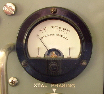
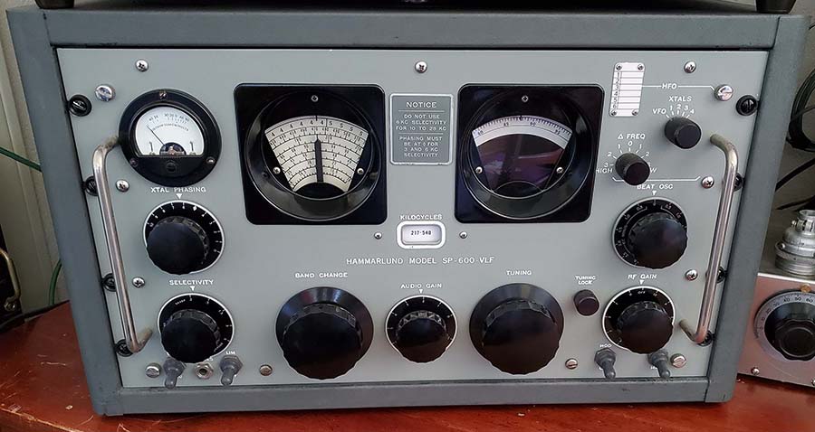
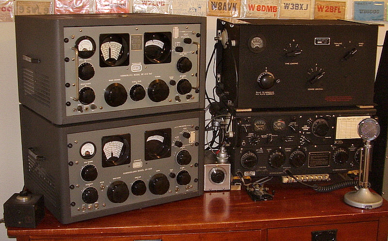
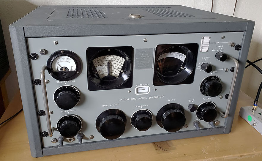
The carrier level meter is unique to the SP-600-VLF


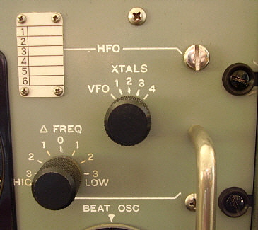
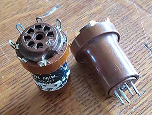
Only four crystal positions are offered in the X option


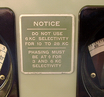
Tag between the tuning and logging dials


No receiver is perfect, so here are a few "negatives" about the SP-600-VLF31


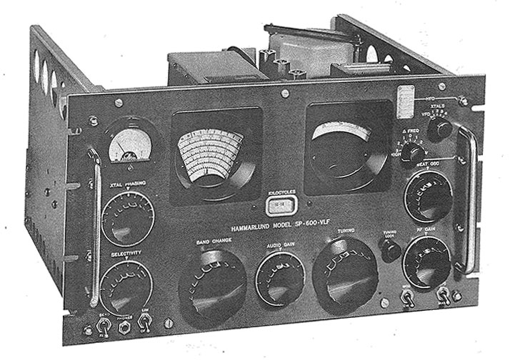
The SP-600-VLF31 Manual - Absolutely One of the Worst

If you're expecting the SP-600-VLF manual to be as detailed and comprehensive as the manuals Hammarlund produced for the HF versions of the SP-600JX you'll definitely be disappointed. As mentioned in this write-up's introductory sentence, the first "questionable writer qualification" happens right off when it's stated that the SP-600-VLF tunes down to an "audio frequency of 10kc." Well, it doesn't stop there but only gets 
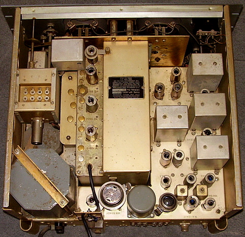
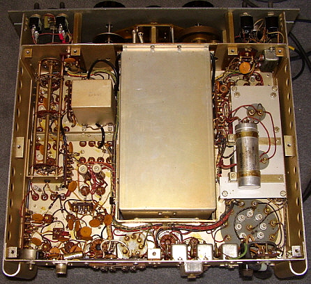
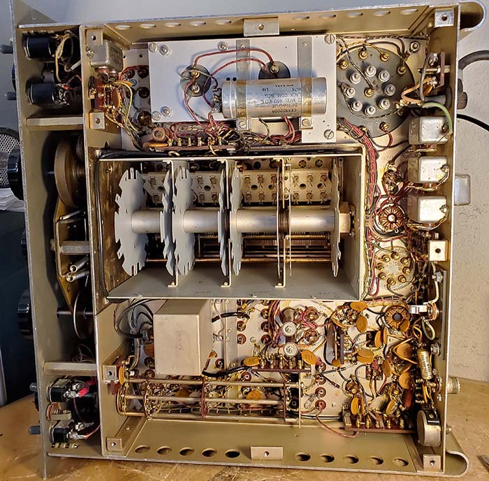
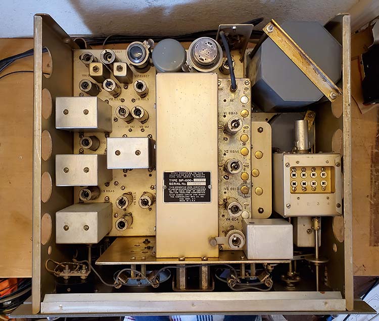
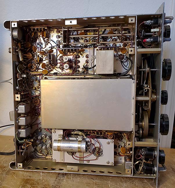
worse. The first significant problem is that there aren't any under-the-chassis component location drawings at all. There's a basic "top view" of the chassis drawing that shows tube locations and transformer identification but nothing to locate smaller individual components under the chassis. There are photographs of under the chassis but nothing is identified so these are no help for troubleshooting. If a specific component location is required it becomes necessary to use the schematic and tracing the wiring (sometimes using an ohm meter) to find the specific component location. There are several component boards used under the chassis and there aren't any drawings or photos to show or identify the components that are on any of these boards - you just have to trace the wiring yourself to find out. All of the HF SP-600JX manuals contained detailed wiring diagrams that illustrated exactly how the receiver was wired, showing wire routing and connections plus showing all of the component locations and how they were connected into the circuitry. Usually there were at least two wiring diagrams because so much detail was shown it couldn't all fit on just one drawing (Hammarlund had to provide these drawings since they were selling so many HF SP-600s to the military.) Not so with the "VLF" manual since there isn't a wiring diagram at all - nothing! If you take out the RF coils (and don't pay attention) there isn't any information in the manual on how to correctly reinstall them. On and on,...only the bare minimum of information is supplied. As far as written circuit descriptions, they're detailed and very usable. At least Hammarlund provided a tube pin voltage/resistance chart and the disassembly instructions are good.  Perhaps there was a separate "Maintenance Manual" for the SP-600-VLF that provided all of the expected (but absent) information,...but I've never seen or heard of one.

By Far, the Worst Alignment Procedure Ever Written -  However, the "all-important" alignment procedure is absolutely awful,...positively one of the worst and most unusable set of instructions I've ever encountered. The alignment procedure reads as if somewhere in the Hammarlund organization it was stated by one of the "higher-ups" that the "600-VLF" alignment had to be "the most accurate alignment possible." So, the writing task was assigned to an engineer that had never performed an actual receiver alignment and,...since "best accuracy" was the goal,...that had to achieved regardless of the practicality of implementation or the time necessary for performing such an alignment or the amount of 
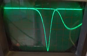
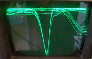
collateral damage brought about by the alignment. While sweep aligning the IF is definitely the best method to achieve symmetrical passbands, you shouldn't have to go out and BUY special equipment to perform the job (the manual actually gives the name of the company and their address where you could purchase the specified special equipment - incredible!)  

Unsoldering Components for an Alignment? You Must be Kidding! - The necessity of unsoldering the "loading resistors" 
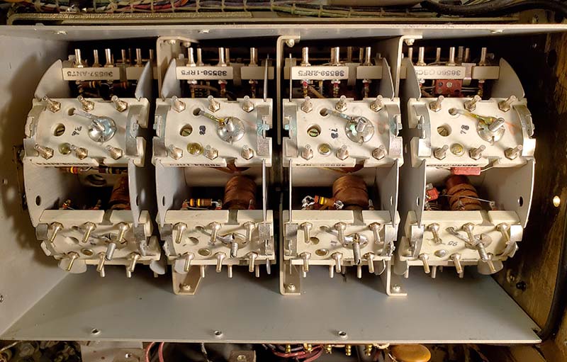
in the RF front-end is totally impractical. It requires removing each of the two RF coil assemblies (ANT and 1RF) from the turret on each of the six bands first to unsolder the resistors. Then the coils are reinstalled in the turret and a RF signal injected at the antenna input. Then a RF Probe-VTVM are used to measure maximum RMS voltage at the 1st and 2nd RF Amplifier tubes for alignment. Then the RF coil assemblies have to be removed again, the load resistors resoldered and the RF coil assemblies reinstalled. That's 12 RF coil assemblies that are "in and out" of the turret four times,...what an "exercise in potentially causing receiver non-functionability due to component damage." Simply unbelievable! In addition to the RF Probe-VTVM RMS measurement, the procedure requires other special equipment that's not always available, e.g., a sweep generator, the "special order" dual sweep trace oscilloscope (dual X vs Y inputs) with a special detector probes to allow the ability to monitor both the sweep input LC and the sweep output LC of the IF transformers simultaneously while sweeping to allow finding coincidence,...on and on. For every section of the receiver, the alignment procedure is overly complicated requiring that certain components or wires be unsoldered from the circuit and then requiring special equipment. There are so many components and/or wires that are disconnected, rerouted, then the measurement/alignment performed and then the component or wire reconnected it would be a miracle if the components or wires could or would be returned to their correct connections. The physical damage that's very likely to happen with the action of unsoldering component leads and wires, then reconnecting and soldering the parts back in place makes one cringe. The amount of components that are tampered-with in the alignment procedure is staggering beyond belief!

Why Publish a Useless Alignment Procedure? - It's almost a certainty that any SP-600-VLF receiver would have been initially owned by either commercial users, such as laboratories, communications or monitoring businesses or possibly by the military. One can confidently rule out any ownership of a SP-600-VLF by any amateurs. Since ALL professional and military equipment would usually be aligned by professional technicians, one would think that the alignment procedure would have been written at "tech-level" to allow each alignment to proceed along quickly and accurately. All of the HF SP-600JX manuals, because those receivers were used extensively by the military, have easy to follow tech-level alignment procedures with no special equipment required. Hammarlund should have employed someone experienced in writing tech manuals to write this section of the 600-VLF manual (or, to keep it simple, just hire one of the Army Signal Corps TM manual writers.) So, why would Hammarlund even publish this impractical alignment procedure? I'm sure that if the SP-600-VLF had been sold in any quantity to the military, there would have been an entirely different, Hammarlund-written but military-style technical manual that would have been similar to the HF SP-600JX manual. But, since civilian purchasers from laboratories or commercial monitoring services, etc., were the likely end-users, commercial technicians would be performing receiver maintenance and that included alignments. But why would commercial techs be expected to use this "impossible to perform" procedure? In reading the SP-600-VLF alignment procedure MANY TIMES, I've come to the conclusion that Hammarlund didn't want anyone going into the receiver to make adjustments and they wrote a procedure that assured that NOBODY would even consider aligning the SP-600-VLF per the manual. Perhaps Hammarlund wanted all SP-600-VLFs returned to the factory for any type of repairs or maintenance and an obtuse alignment procedure made sure of that. But, I doubt that even Hammarlund aligned the SP-600-VLF as described in the manual (so, what should you do? Read on,...)

Does the Alignment Procedure in the Hammarlund SP-600-VLF Manual have to be Used? - In looking at the schematic of the SP-600-VLF, it's obvious that it's a standard single conversion superheterodyne. There's nothing special going on in the circuits. It can (and should) be aligned just like any other superheterodyne. The bulk of the receiver circuit 
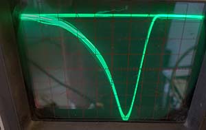
operates at 705kc. Use 705kc for the IF. For the best results, sweep align the IF. First, "peak align" at 705kc and then apply the sweep signal at the grid input on each IF stage and do minor tweaks to the appropriate IF transformer for the best shaped passband. Proceed from the last IF to the Mixer always with the 'scope on the detector output, the Diode Load (this is basically how a standard sweep IF alignment is performed,...more details on sweep aligning the IF of the SP-600-VLF in the "2024 Workbench Visit" at towards the 
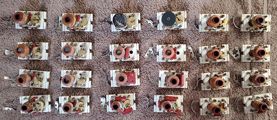
end of this article.) The turret coil assemblies function at various other lower frequencies than the IF. A RF signal generator (or a very stable Function Generator) that can produce a RMS voltage output down to 10kc is necessary. Adjust the turret coils as if it were a HF SP-600JX but use the frequency table in the manual (at least that part of the alignment procedure isn't corrupted.) Align the BFO and the Amplified AVC to 705kc. Adjust the 455kc IF conversion for maximum output at the IF OUTPUT. Use a VTVM on the Diode Load and adjust for peak negative DC voltage with the AVC off.

What is interesting is that my detailed inspection under the chassis of the entire SP-600-VLF receiver and detailed RF coil assembly inspection revealed that NONE of the components or wires that were supposed to have one end unsoldered and "lifted" had EVER had the original solder joint disturbed. That indicates that whomever performed the maintenance on this SP-600-VLF read the alignment procedure in the manual and knew it was unusable and probably aligned the SP-600-VLF using conventional RF-IF alignment techniques. And, this was probably the method used for several alignments over the years. So, don't be afraid of the SP-600-VLF,...it's a standard single conversion superhet that can be aligned like any other similar type of receiver. Yes! I've aligned my SP-600-VLF, including a sweep alignment of the IF, following conventional procedures and the receiver functions great.

More Issues,...but these are minor ones

Dial Slippage - a Chronic Problem with all SP-600 receivers (but there's an easy solution)  - All SP-600 receivers mechanically drive the tuning using the same set up. A brass drive wheel is rotated with the Tuning knob. This wheel in turn drives, by friction, a brass reduction wheel that is spring-loaded against the drive wheel. The reduction wheel is grooved and mates with the Logging dial driving it, by friction, at its perimeter. Driving the Logging dial shaft tunes the receiver tuning condenser through the gearbox. If contaminates are allowed to accumulate on the friction drive surfaces eventually dial slippage will be the result. Although some SP-600 enthusiasts believe that the "S" spring used for loading the reduction wheel causes the slipping, I've seldom had just the spring be responsible for dial slippage. Almost always, dirt and grease will have collected on the friction surfaces of the brass wheels or on the rim of the Logging dial and this is what is causing the slippage. Thorough cleaning is necessary to correct the problem. Fortunately, all parts are accessible without any disassembly. The brass wheels can be accessed with the receiver on its side and the Logging dial rim can be accessed from the top. Clean all friction surfaces with denatured alcohol. I use several Q-tips to clean the brass wheel surfaces. Repeat the cleaning until the Q-tips don't turn black. On the rim of the Logging dial, I use a small piece of paper towel that is dampened with denatured alcohol. Again, clean until the towels don't turn black. Remove and check the "S" spring. It should be straight or slightly bent out. If it's bent inwards then the spring load will be somewhat reduced. You can expand the "S" spring by just bending it outwards with your fingers. Reinstall the "S" spring. As an added help, check the rotation of the logging dial and how much resistance to movement there is in the gearbox. Years of storage with no use or no maintenance may dried up any lubrication. It would certainly help to lubricate all of the shaft bearings with a drop or two of 10W machine oil. As always, don't "over lubricate" and just apply a drop or two of machine oil only where needed. Also, check that the Dial Lock is completely open and not "dragging" on the Logging dial. Check the SP-600 tuning now. It should not slip and should be "velvet smooth."

UPDATE: Jan. 1, 2018 - The slipping dial is back. Although I haven't pulled the receiver out of the cabinet I can see what I think is the problem. The logging dial rim has a small gouge that I think is causing the slippage since this "dent or gouge" changes the dial friction in the drive wheel groove when the gouge comes around. I also noticed that the logging dial has a significant bend so it isn't really engaging into the drive wheel groove with the same "fit" each revolution of the drive wheel. To repair this will be a receiver out of the cabinet and front panel off since I'll have to dismount the logging dial for straightening and repair of the gouge. I'll do this after the Longwave season is over - probably around March.

UPDATE: May 1, 2018 - A Solution That Works and isn't Difficult to Implement - Slipping dial issue required pulling the receiver out of the cabinet and then disassembling to the point where the front panel could be removed. The dial lamp assembly over the logging dial has to be removed. Then the three screw mounting plate is removed and the logging dial can be removed. Close inspection revealed that near "45" on the dial rim there was a deformation that had a "lumpy" feel to it. Also, between "50" and "55" was another rough area. I carefully dressed these areas with a very fine jeweler's file. The dial also had a warp that was easy to take out with minor flexing of the dial. Upon reinstalling the dial on the hub, I found that the slipping was still happening in the same areas. I readjusted the "S" spring for a greater load against the drive wheel. No improvement.

The Slipping Dial Solution - I thought about how improve the "grip" of the brass against brass surfaces and came up with the idea of using rosin. I dissolved some powdered rosin in some denatured alcohol to make a thin (viscosity like water) mixture. I used a small paint brush to apply the rosin mixture into the drive wheel groove. Then I rotated the logging dial to transfer some of the rosin mix to the rim of the dial while applying more rosin to the groove with the paint brush. I let the mix dry (alcohol evaporates.) That did it. No more slipping - none at all! I didn't need much rosin-mix, just a little brushed just into the drive wheel groove worked great. If the rosin somehow disappears from the drive wheel groove in the future, it's very easy to reapply the rosin-mix. Hopefully, the "grip" will last for quite awhile. NOTE: The rosin-mix probably should be reapplied each year for best results. For an update on the rosin/alcohol mix read the update for Jan 6, 2021 further down this page.

Jan 3, 2021 - Maintenance Required - I had been noticing that changing the SELECTIVITY would cause signal loss and erratic reception. The problem turned out to be in the SELECTIVITY switch that apparently I'd never cleaned. De-Oxit and a small paint brush (and cleaning out a few spider webs) got the switch operating fine. This seemed to clear up the problem. This is a common problem with the HF SP-600 also. I've noted that for quite a while now the dial is again slipping. Not nearly as bad as before but it's getting worse. More rosin/alcohol mix needs to be applied to the drive wheel.

UPDATE: Jan 6, 2021 - More Rosin - The rosin mix was still working fine in the small groove of the idler wheel that actually drives the dial. The beveled drive wheel that interfaces with the idler wheel was where the slipping was happening since I hadn't ever applied the rosin mix there. I cleaned the bevel with alcohol and several Q-tips turned black indicating dirt or contamination of some type. Just cleaning the bevel gear helped with the slipping but I applied new rosin/alcohol mix to ALL drive surfaces this time. After the rosin mix dried, no slipping. Just as another precaution, I adjusted the spread of the "S" spring for the dial drive. This increases the engagement force of the idler wheel into the bevel of the drive gear. The dial drive now seems excellent with no slipping. We'll see how long this lasts - I think I can probably go about two years between the "rosin" treatments - not bad,...it's an easy fix. NOTE: I've actually gone three and half years and still no slipping - 2024.

Other Minor Complaints

Shielded Magnetic Loops - The SP-600-VLF does tend have a high noise floor that makes using certain types of wire antennas in the MW and LF spectrum nearly impossible. Best performance on MW with my SP-600-VLF has ALWAYS been with a loop antenna. At first, I was using a homemade remotely tuned loop that worked very well. I switched to a Pixel Loop in November 2019 and it also works quite well. My Pixel Loop was purchased used and it's an old one that was actually built by Sirius years ago. Nowadays, Pixel Loops are still available but the disadvantage is not only the expense of a Pixel Loop (about $500) but they always seem to be on "back order." Pixel Loops are available from DX Engineering but expect to wait for actual delivery. The other good LW loop was the Wellbrook Loop. They came from the UK but now Wellbrook is out of business. Wellbrook Loops are frequently seen for sale "used." The Wellbrook Loops seemed to have problems with their LNA although, when they were still in business, they would replace them if the failure was component or workmanship related and they could be purchased separately, if needed. I've seen replacement LNAs for sale by private owners on eBay. Chameleon also made a high quality shielded magnetic loop a few years ago but it was mainly for HF and didn't perform as well as expected on MW or LF (this opinion was expressed in an Internet review of the Chameleon loop.) There are other much less expensive loops that are made out of coax for the loop portion using the coax braid for the shield and the center conductor for the antenna. These type of shielded magnetic loops are mainly designed for HF, so MW and LF may not perform as well as expected (again, this was an Internet opinion.) Also, these coax loops aren't particularly durable when used outside. As an indoor loop they might be an inexpensive alternative. The coax loops are about half the price of a Pixel Loop.

Homemade Remotely Tuned Loops - These types of loops are not difficult to build and their performance is usually a vast improvement over a wire antenna. Finding the MVAM-108 varactor diodes (bias voltage changes the capacitance for remote tuning) might be difficult nowadays. If the MVAM-108s can be found then building a remotely tuned loop is easy and the bias voltage can be provided by a 9 volt battery and a high resistance 10K potentiometer with 1 meg isolation R. A switch is necessary to isolate the battery when the loop isn't in use. Plans for a remotely tuned loop are in Part 4 of "Vintage Long Wave Receivers." Use Home/Index at the end of this article for navigation.

Dual Crystal Filters - The Selectivity options are limited because the Band Pass crystal filter and the Phasing crystal filter that are always in the circuit for every selectable bandwidth, even the 6kc bandwidth. Nowadays, there are virtually no Voice-Music signals being transmitted below 530kc. The only possibilities for music would be on 540kc AM-BC and for Voice on 530kc public service broadcasting. I haven't heard the TWEB NDB RWO 394kc from Alaska in a couple of years. TWEB NDBs transmit Voice weather with MCW ID. RWO has probably been decommissioned. LW-BC is nowadays (2024) limited to just a couple of stations that can't be received in the western USA. So, there really aren't any Voice-Music stations transmitting that would benefit with a non-crystal filter IF bandwidth position. The Crystal Filter operates differently than a typical crystal filter in that the entire rotation from 10 down to 0 on the PHASING dial scale varies the bandwidth from maximum (10) to minimum (1.) There is also a very narrow peak that moves around the passband as the PHASING control is rotated that can be used for peaking a particular heterodyne tone in CW. The first Crystal Filter is essentially non-adjustable and is actually a crystal-controlled Bandpass Filter centered at 705kc.

Dial accuracy is typical of non-Collins gear from the 1950s. The accuracy is very good (after an alignment) but the dial resolution could be considered vague. With the inclusion of the Logging Dial it's obvious that Hammarlund expected extreme accuracy to be determined with a Heterodyne Frequency Meter and then the Logging Dial used for accurate frequency reset. All typical of 1950s designs, so this is not unexpected.

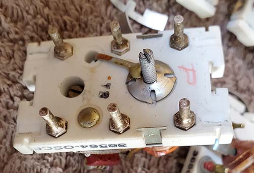
Hard to Access BFO Tube - Accessing the BFO tube will require removing the shield-box over the LO switch for the Crystal Oscillator. There's a hole at the back of the shield-box that allows access to the mounting screw. Don't remove the screw,...just loosen it. Then the shield-box can slide upwards (it's a long slot that the screw works against) to clear the screw. With the switch shield-box dismounted, now there's easy access to the BFO tube although a long-handle tube puller might make removal of the tube a bit easier. When BFO tube testing is completed and a good tube installed, then reinstall the LO switch shield-box. When aligning the receiver front end, this shield box has to be removed to allow access to the OSC L-C adjustments.

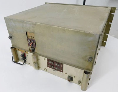
Hammarlund SP-600 Cabinet Rack Mounting Screws, Straps and Holes - The eight holes for the rack screws to mount the receiver into the cabinet don't have any threads. In fact, they're just .250" diameter holes. Instead, a steel strap with four 10-32 tapped holes is placed behind the cabinet holes with the receiver in place in the cabinet. Reaching around the top side of the receiver side panel, the steel strap can be moved around with the fingers (sort of.) The tapped holes have to be aligned with the cabinet holes and with the receiver rack notches. Then one of the 10-32 rack screws can be hand-threaded into one of the strap holes. Once one screw is threaded in then the strap won't fall and the other three screws can be installed. This maneuvering of the steel strap to align with the cabinet holes has to be repeated for the other side. Once all eight screws are threaded in they can then be "snugged" - that is, not over-tightened. These two steel straps really are time-consuming to deal with and many times in trying to get the strap holes aligned with the cabinet holes you'll end up dropping the strap and it will fall to the bottom of the cabinet. That requires pulling the receiver out of the cabinet to retrieve the strap, which is a real pain. Though I haven't done it, I've thought about drilling two holes in the cabinet rack mounting flange to accept 6-32 flat head screws. Then drill and tap the strap (6-32) so that the mounting of the strap has the four rack 10-32 holes aligned with the cabinet .250" diameter holes. The flat head screws wouldn't interfere with the receiver mounting and the straps would always be aligned correctly and couldn't fall down inside the cabinet. A good idea,...I just haven't done it yet.
 

Miscellaneous Information

Cleaning Up a Mod - the former owner of this SP-600-VLF had only been in possession of the receiver for about a month but that was long enough for him to "hamster" install a mod that added a standard phone jack to the rear chassis apron for easy connection to the 600Z line (the "punched" 1.0" diameter hole on the back apron was a real disappointment to see when I got the receiver.) The mechanical workmanship was barely acceptable but the wiring was not even close to acceptable. Just a sloppy job with burned wire insulation and gloppy solder joints. I replaced the burned insulation wires with 1950s vintage fabric-covered wires and cleaned the terminals of the excess solder. The joints were then resoldered with minimal solder for a better connection that was neater in appearance.

The bottom chassis cover was bending due to it not clearing the garolite insulator that had been used for the phone jack installation that had to have the jack insulated from the chassis. The insulator had to be removed and trimmed on three sides by .250" to prevent interference and to have the insulator "square" - nothing screams "hamster" more than non-square, hacked-out pieces, be it fiber material or sheet metal. After "squaring" the garolite now doesn't interfere with the bottom cover installation.

It's still a mod, which is unfortunate, but I have to admit it's really convenient to use the jack for audio output rather than having to utilize the screw terminals. But, the following is a method to allow easy connection to the 600Z output without hacking up the receiver,...

HINT for Convenient 600Z Audio Connection: To have the convenience of a rear-terminal 600Z access in a phone jack without damaging the receiver's originality, I make up a two-conductor cable with spade lugs on one end and a cable-type barrel phone jack on the other end. Connect up the spade lugs to the receiver's screw terminal rear chassis 600Z output, route the cable around the receiver to be easily accessible and then just plug in whatever 600Z load you want into the cabled barrel phone jack. I've made up several of these audio cables to allow easy 'phone connections - all done without cutting or hacking the receiver.

Other Semi-Interesting Observations - For quite a while, I thought this SP-600-VLF31 SN: 20101 was built in 1955. That thought was based on the date code stamp of "June 1955" on the back of the front panel. Just recently, when I had the bottom cover off, I happened to notice that the electrolytic filter capacitor was date coded "1-58" and the tub-mount electrolytic capacitors were date coded "7-57." It appears the latest date code I found on a component was the "1-58" on the filter capacitor. So, the "VLF" had to have been assembled after that date of January 1958. My guess would be around April 1958 at the earliest since the manufactured and dated capacitor had to be shipped to Hammarlund, received and placed into their stock, pulled from stock for assembly of the receiver and then completion of the assembly. I would think the quickest that could happen would probably be three or four months from the component stamped date code.

I don't really think that the front panel has been repainted. Actually, it looks like just the engraving fill has be redone. The quality of the engraving refill is very poor and that lead me to believe that a panel repaint had filled-up the engraving and that resulted in the poor quality of the engraving fill paint. After having the front panel off and examining it closely, I'm pretty sure the paint is original and just the engraving fill has been redone and redone poorly.

Toggle Boots - During some rework that required removing the front panel, I noticed that the gray rubber boots over the toggle switches had deteriorated to the point where two of them ripped and came apart. Fortunately these rubber boots are still being made by the same manufacturer and using the same part number. I ordered a new set of four gray boots from Grainger via their eBay listings. The price was $4.50 per boot. The boots are for 15/32"x32 toggle switch barrels and are manufactured by APM HEXSEAL (part number is IN1030.) I know these aren't OEM but I think these additions improve the front panel appearance and aren't serious deviations from originality.

How I Acquired this SP-600-VLF31 - Around 2014, an old friend of mine (and a fellow LW enthusiast) purchased this SP-600-VLF from a mil-rad collector he knew in Southern California. The receiver was very dirty having been stored in a shed. It had what appeared to be oxidation on top of the chassis. Circuit-wise, it was in somewhat non-working condition. It didn't function very well on any of the bands and didn't work at all on band 3 so it was bargain-priced. My friend asked if I'd take a look at it, which I did. There were a couple of "hamster induced" soldering problems in the turret that affected coil connections that caused the receiver to not work on band 3 (RF coil assembly 2RF3.) I also replaced a couple of tubes. When I returned the now basically working 600-VLF to him I gave him the usual speech,..."if you ever want to sell this receiver, please let me know." Well, little did I know about a month later, the SP-600-VLF would be offered to me as a method of payment to repair and align a couple of other receivers this guy had. My friend's QTH was in an apartment building that was practically in downtown Reno, Nevada. The RFI/EMI noise at that location was so intense he couldn't hear anything with the SP-600-VLF, even when using a Pixel Loop antenna (actually, he couldn't really hear much of anything on any frequency on ANY receiver at his location,...and, yes, I tried some of his receivers at his QTH and the RFI was so intense reception of any radio signals was almost impossible - other than FM.) Frustrated with the receiver and the terrible RFI conditions at his QTH, he just wanted to get rid of the SP-600-VLF. So, that was how I ended up with the "VLF" for just doing some repair/alignment work. Since "time is money" maybe it wasn't exactly free but it was pretty close to it.

Is the SP-600-VLF Really the Best Vacuum Tube LW Receiver? - Why do I consider the SP-600-VLF the best overall vintage tube-type longwave receiver? First, it has more than enough sensitivity for great performance on a shielded magnetic loop antenna. For selectivity, the dual crystal filters are always in the circuit and the Phasing Control does work very well to narrow the bandwidth to "super narrow" and that reduces the noise even further allowing very weak signal detection. Reliability is excellent but the receiver is fairly easy to work on if it does become necessary (but don't expect any help from the manual.) The tactile interface, with large knobs and ultra-smooth tuning, is fabulous, and that, combined with the receiver's commanding bench presence that dominates the station-landscape, all adds to the sublime "radio experience" when using the SP-600-VLF. Since SP-600-VLF receivers are rarely seen and nice ones are usually expensive, the biggest disadvantage will be trying to find a good one that really and actually is for sale at a somewhat reasonable price.


630M Amateur Operation

Depending on your interests, the SP-600-VLF could end up as a top-tier receiver that can only be used to hear just a few interesting signals now and then. Fortunately, now there are two amateur bands, one MW and one LF, that can present a real challenge for the SP-600-VLF and for the MW/LF amateur radio operator. 

630 Meters - 630M is a tiny band - only from 472kc to 479kc. Regulations allow using any mode with 5 watts EIRP.  In 2018 to 2019, I successfully used the SP-600-VLF as the receiver in my 630M station. I used a six-foot remotely tuned loop antenna for reception. The photo below shows the station. I switched to a Pixel Loop, a shielded magnetic loop in Nov. 2019.  One does have to be aware that most of the 630M activity shuts down for the summer months. Generally, October through April will have the greatest number of stations on the air. Of course, near-field 630M stations can always be worked.

2200 Meters - The other amateur LF band is 2200 meters. This is 136kc and in other parts of the world can be used by amateurs to run fairly high power. Not so here in USA. EIRP is only 1 watt, but since practical 2200M antennas are so inefficient at that wave length, it might take several hundred watts input to achieve 1 watt EIRP. The other problem is noise and propagation. The 2200M band is a particularly noisy part of the spectrum and propagation is almost all ground wave. So far, it seems that 2200M doesn't have nearly as much interest as 630M does, but that might change in the future.

630M QSO with NO3M from Pennsylvania - Dec 7, 2018 - In November, 2018, I had a sked with NO3M on 473kc at 1900 PST. I didn't think I'd be able to hear Eric since his QTH was in Pennsylvania - I've never even heard a NDB from Pennsylvania! Total surprise when I heard "CQ CQ CQ de NO3M NO3M NO3M K." Eric's signal wasn't strong, maybe S3 but it was Q5. I answered the CQ but Eric couldn't hear me. I was using the Hammarlund SP-600-VLF and the six foot remotely tuned loop. My transmitter was the ART-13A with CU-32 loading coil to a 163' End Fed Wire. I was amazed that I could actually copy a ham signal that originated almost on the East Coast. As mentioned above,...the SP-600-VLF is sensitive and it seems to work well with the remotely tuned loop antenna. I heard Eric several times after that but was never able to establish a two-way QSO until December 7, 2018. Eric was RST 549 and my report was 539.

Other 630M 2X QSOs - I also had 2X CW QSOs with K6KBE from California, KI6R from California, W7IUV from Washington and WØSD from South Dakota.

WA7YBS 630M Station

The 630M station consists of two Hammarlund SP-600 receivers. The top receiver is the SP-600-VLF31 tuning from 10kc up to 540kc. The bottom receiver is the Hammarlund SP-600-JX21 tuning from 540kc up to 54mc. The small box to the left of the JX-21 is the remote tuning for the six-foot loop antenna used on 630M for reception. The HF receiver output is to a floor speaker. The LF receiver output is to 600Z ohm 'phones. 

The transmitter is an ART-13A with O-17/ART-13A LFO installed allowing operation from 200kc up to 600kc. On top of the ART-13A is the CU-32/ART-13A Antenna Loading Coil. The CU-32 allows the ART-13A to match a variety of antenna types on LF. Both the HF output and the LF output from the ART-13A are routed through the CU-32. In my setup, the output of the CU-32 is connected to the HF antenna when "FIXED ANT" is selected and is routed to the 630M antenna when "TRAILING ANT" is selected. The silver box to the left of the ART-13A is an auxiliary condenser that aids in loading the transmitter on 75M. The J-38 hand key is for LF-CW and the mike is for HF phone. LF transmitting antenna is an end-fed wire 166 feet long. HF antenna is a 135' CF Inv-vee with 99' of ladder line to a Viking KW tuner.

630M Operation: Needless to say, with three antenna switching relays that follow the transmitter keying, this 630M station was very noisy while operating. The end-fed wire antenna was operated against the house ground, certainly not the best way to get the most out of an end-fed wire. The antenna for the SP-600-VLF was a home-made remotely tuned loop that measured six feet diagonally. I had this 630M station hooked-up from 2018 through 2019. Besides the extremely noisy operation, a new furnace thermostat reacted to the end-fed wire RF by turning on the furnace anytime the transmitter was keyed. I disassembled this station in 2019. My other 630M attempts haven't been as successful as this first station. The most successful involved using a BC-375 transmitter to an end-fed wire. Copied by KD6TKX at RST 339. I couldn't receive KD6TKX because both the BC-348 and the BC-375 were operating on dynamotors powered by a PP-1104-C. The RFI created by the dynamotors and the PP-1104-C magnetic amplifier was intense.

Interesting Signals on 630M - Due to the Private Ownership and Operation of These Beacons, Schedules are very likely to Change at any time,...they might not even be in operation anymore (2024)

Jan. 7, 2021 - 1925hrs PST, while listening on the SP-600-VLF with the Pixel Loop. I was tuning the 630M band and was surprised to hear a "beacon." It was actually a ham propagation beacon sending CW at about 10 WPM. "WA4SZE/BEACON" was the message. RST about 539. WA4SZE is located in Manchester, Tennessee which would be good DX for a NDB but it's really good DX for a ham beacon.

Another Beacon - Mar 2021 - WB6ZBX Jeff in Fresno, California has set up an old Nautel NDB transmitter to operate on 478kc. Jeff has modified the Nautel to operate mode A1 rather than A2 (MCW.) The power output is 125 watts to an inverted "L" antenna with an external matching network. The antenna is 55ft vertical and 90ft horizontal (ERP is still < 5W.) The Nautel is on a timer and only operates from 1730hrs to 1830hrs Pacific Time and from 2100hrs to 2300hrs Pacific Time, every day. The beacon sends "de WB6ZBX/B" every 10 seconds. I've copied WB6ZBX/B here in Dayton, Nevada at about RST 559 using the SP-600-VLF and the Pixel Loop.

Another Beacon - September 2, 2021 - N6NKS, Steve McGreevy of auroralchorus.com is operating a 630M beacon on 474.7kc in the A1 mode. The transmitter is homebrew and the antenna is a 24ft tall vertical with C-hat. I copied N6NKS at 0550hrs in the morning. RST was 549. I was using the SP-600-VLF and the Pixel Loop.


NDB Reception Log for the SP-600-VLF31 for 2022-23

2022 Operation Check-out - Sept. 15, 2022 - In setting up the SP-600-VLF for the coming LW season thought I'd check-over the receiver's performance since I didn't use it much at all last year. I tested all of the tubes - it's been a few years since I did that. Surprisingly, one of the 6AL5 rectifiers was shorted (probably just high leakage,) one of the 6BE6 mixers was weak and the 12AU7 was also weak. All of the 6BA6 tubes tested "as new" except one that tested below minimum (the Driver tube.) All of the weak tubes were replaced with NOS tubes and the bad 6AL5 was replaced with a "used-tested good" 6AL5 (it's just a rectifier.) I also cleaned the Selectivity switch with DeOxit using a small paint brush for application (this switch is always a problem, even on the HF SP-600s, requiring cleaning every couple of years.) Interestingly, when I finished up I had the "VLF" and Pixel loop combo set up around 425kc and coming in strong was KPH sending 25WPM CW for their Saturday scheduled transmissions. KPH runs significant power and has good antennas in a superb location so daytime reception is pretty easy,...it's just they're only on for a short time each Saturday afternoon on 425kc. Everything else seemed okay so we're ready for LW Season 2022-23.

2022-23 NDB Log - I never created a NDB Reception Log for the SP-600-VLF because at the time I acquired the receiver (in 2014) I was just trying to log as many NDBs as I could. Well, times have changed and the number of NDBs on the air has been drastically reduced so the chances of coming up with newly heard NDBs is also greatly reduced. I haven't logging a "newly heard" NDB in over two years (it was 2 yrs 1 month & 16 days, then heard FF 337kc on 12-23-22) So, last year I decided that instead of concentrating on just increasing the total number of stations logged, I'd see how many NDBs I could log just using one receiver for a specific time period. The first time I tried this was in 2009 for a test of the 1920s RMCA/WSA IP-501-A receiver where I logged over 100 NDB stations in just three weeks. In late-2019, using the RACAL RA-17C-12 and LF Converter, I logged 97 NDBs in one month (with seven being "newly heard" NDBs.) Nowadays, when doing these tests, none of the NDBs are "newly heard" stations, I've logged and heard all of them before. But, to some receivers it's the first time the NDB has been heard on that receiver. Like the 57 NDBs tuned on the RCA CR-91 last year (two week period) - no "newly heard" NBDs, but they were all "new" for the CR-91. Now, this isn't exactly the case with the SP-600 VLF. I've logged lots and lots of NDBs on the "VLF," many "newly heard" ones. BUT I've only kept track of the newly heard stations with the "VLF" not the total number of NDB stations received and not exactly when any of the stations were received. So, this 2022-23 NDB log for the SP-600-VLF is going to start at the beginning of LW Season with mostly morning listening sessions and will continue into the switch-over to all night-time listening with the time change back to standard time set for Nov 6th. I'll be using the Pixel Loop unless otherwise noted in the loggings. Pixel Loop oriented NE-SW unless otherwise noted.


Sept 19, 2022  0550hrs-0610hrs PDT

MW 408kc - Moses Lake, WA
MOG 404kc - Montegue, CA
TW 389kc - Twin Falls, ID
SX 367kc - Cranbrook, BC, CAN
MEF 356kc - Medford, OR
LLD 353kc - Lenai City, HI
XX 344kc - Abbottsford, BC, CAN
RYN 338kc - Tucson, AZ
POA 332kc - Hilo, HI
DC 326kc - Princeton, BC, CAN

Condx okay, a little late in morning for this early in Sept, very little noise but signals not very strong. MOG and RYN were the only strong signals. Both Hawaiian NDBs heard.

10 stations tuned in 20 minutes. Pixel  Loop.
 

Oct 11, 2022   0535hrs-0610hrs PDT

DC 326kc Princeton, BC, CAN
WC 332kc White Rock, BC, CAN*
OIN 341kc Oberlin, KS*
POY 344kc Powell, WY*
XX 344kc Abbottsford, BC, CAN
AL 353kc Trina, WA*
MEF 356kc Medford, OR
YAZ 359kc Tofino, Van Is, BC, CAN*
RPX 362kc Roundup, MT*
SX 367kc Cranbrook, BC, CAN

JJY 40kc Mt. Otakadayo, Japan - PE Time

Condx much worst than expected for mid-October. Weak signals, no atmospheric noise, tried both Pixel Loop and wire antenna with no real difference. Tuned in JJY 40kc while using wire. 6 new, 16 total

Evening before Time Change

Nov 1, 2022  2215-2230hrs

Once again conditions seem to be poor. Signals are very weak except MOG 404kc. Very few NDBs tuned in or even heard. I did copy YXL 346kc Sioux Lookout, ON and SB 362kc in Sudbury, ON,... so DX NDBs can be received. It really seems like most signals aren't there. It might be where I moved the Pixel Loop which is about in the upstairs-center of the house now. I'm going to move the Pixel Loop back where it was before and see if reception improves. Another test soon,...hopefully with better performance and reception.  2 new, 18 total

Nov 3, 2022  2210-2220hrs

Test reception about the same with the Pixel back in its old location. The few NDBs heard seem to be strong, like DC 326kc in Princeton, BC or MOG 404kc. SX 367kc and XX 344kc were the only other NDBs heard. It sounds like a mass decommissioning of NDBs has happened. It doesn't seem to be the Pixel or the SP-600-VLF since DC and MOG were strong.

Evening After Time Change

Nov 18, 2022

The absence of many familiar NDBs is certainly noticeable. I've tried three different receivers and two different antennas with the same results. I'm receiving stations like DDP 391kc in Puerto Rico (different receiver,) so I'm sure conditions are normal. Several of the midwest NDBs are easily received. But, it seems like a very large number of NDBs have been decommissioned during the summer of 2022. I checked classaxe RNA and there appears to be many NDBs that have been decommissioned (or there are plans to.) This appears to be the same for Canadian NDBs. 

Nov 22, condx seem to be improving but still many familiar NDBs are missing. 

Dec 1, 2022    2207hrs to 2229hrs

LGD 296kc LaGrande, OR*
UNT 312kc Penticton, BC, CAN*
DC 326kc Princeton, BC, CAN
MA 326kc Midland, TX*
RYN 338kc Tucson, AZ
OIN 341kc Oberlin, KS
XX 344kc Abbottsford, BC, CAN
POY 344kc Powell, WY
SBX 347kc Shelby, MT*
MEF 356kc Medford, OR
GGF 359kc Grant, NE*
RPX 362kc Roundup, MT
6T 362kc Foremost, AB, CAN*
SX 367kc Cranbrook, BC, CAN
EX 374kc Kelowna, BC, CAN*
GC 380kc Gillette, WY*
CNP 383kc Chappell, NE*
IAETEU 388kc ?
FMZ 392kc Fairmount, NE*
MOG 404kc Montegue, CA
CO 407kc Colo. Sprs., CO*
MW 408kc Moses Lake, WA
LYI 414kc Libby, MT*
GRN 414kc Gordon, NE*

Cndx seem much better now than in November. Pixel Loop NE-SW. 24 stations tuned in about 25 minutes. Best DX either 6T in Alberta or MA in Texas. 4 Nebraska NDBs. The beacon that ID'd "IAETEU" was moderately strong and sent this call several times - always the same - so it probably wasn't mis-keyed or mis-programmed. Sometimes these weird calls belong to off-shore oil rigs that have their own heliport.

13 new shown with * - total is 31 stations

Dec 4, 2022     2205hrs to 2230hrs

TOR  293kc  Torrington, WY
QR    290kc   Regina Int'l AP, SK, CAN
POA  332kc   Hilo, HI
ODX  355kc  Ord, NE
K2     376kc  Olds-Didsbury, AB, CAN
TW    389kc  Twin Falls, ID
 

Cndx okay, some static crashes from storm in Sierra. A few very weak stations heard below 290kc, RST 119. 17 stations heard, 6 new shown above. Except for a few "blow-torch" signals, most NDBs copied are RST 439 or so. Solid copy but fairly weak signals.
Total for SP-600-VLF is now 37

________________________________

Dec 9, 2022     2215hrs to 2232hrs

WG 248kc Winnepeg, MB, CAN
XC  242kc Cranbrook, BC, CAN
BR  233kc Brandon, MB, CAN
HLE  220kc Hailey, ID
 

Cndx good, storm coming in, some "pops"
Tuned in 9 stations in 17 minutes of listening. 4 new NDBs shown above (all below 250kc.) Best DX probably POA in Hawaii but Manitoba is good DX too (QR also copied.)

Total for SP-600-VLF is now 41

Dec 23, 2022    2205hrs to 2235hrs

JDM 408kc Colby, KS
YWB 389kc West Bank, BC, CAN
HAU 386kc Helena, MT
ON 356kc Penticton, BC, CAN
YXL 346kc Sioux Lookout, ON, CAN*
FF 337kc "Hamre" Fergus Falls, MN - new #383
XH 332kc Medicine Hat, AB, CAN
YQF 320kc Red Deer, AB, CAN

24 stations tuned in 30 minutes. Cndx Good.
7 new stations for the SP-600VLF shown above.
1 newly heard NDB, FF 337kc Fergus Falls, MN
being #383 after a very long "dry spell" - last new NDB was in Nov 2020.

Total for SP-600-VLF is now 48

* I had YXL listed on Nov 1 and counted it in the total then. Although 8 stations are shown above, only 7 are counted. So 41+7=48 Total

___________________________________

Dec 25, 2022   2145hrs to 2215hrs

YCD 251kc Nanaimo, BC, CAN
VR 266kc Vancouver, BC, CAN
YPW 382kc Powell River, BC, CAN
SB 397kc San Bernardino, CA

17 stations tuned in 30 minutes. Cndx noisy until 2200hrs, then quiet. Pixel Loop N-S,
4 new, shown above.

Total for SP-600-VLF is now 52

Dec 30, 2022  2205hrs to 2225hrs

17 stations heard, none new
Pixel Loop E-W
  _________________________

Dec 31, 2022 to Jan 20, 2023

Intense storm on New Year's Eve with heavy, wet snow toppled my 40ft Locust tree onto outdoor wire antenna pulling it to the ground. Snow still on ground three weeks later. Just was able to get Locust tree remains cut up and removed Jan 18, 2023. For sometime now, I've suspected that the Pixel Loop's performance is down from former years. So, put up a sloper wire antenna 84 feet long on Jan 28. Much later, I replaced the RG-6 cables I was using on the Pixel Loop with high-quality cables and that brought the performance back.

_____________________

Jan 28, 2023 2150hrs to 2220hrs

LW 257kc Kelowna, BC, CAN
PND 356kc Portland, OR
SIT 358kc Sitka, AK

84ft sloper wire antenna, cndx good

16 stations tuned in 30 minutes, 3 new

Total for SP-600-VLF is now 55

Feb 13, 2023  2205hrs to 2230hrs

21 stations tuned in, none were new for the SP-600-VLF. Best DX was WG in Winnepeg, MB. New antenna is a 240'x108' "T" wire antenna that provided strong signals and the noise level wasn't too bad.


Summary - A total of 55 different NDBs logged over the 2022-23 LW Season. Quite different from the 100 NDBs logged with a 1920s regenerative receiver (IP-501-A) in just three weeks 14 years earlier. But, it illustrates just how many NDBs have been decommissioned over the past decade. And, it's only getting worse. The future of airport NDBs is tenuous and with no USA pilots using them for navigation, the airports figure why maintain something that's not even used anymore. In remote areas in Northern Canada, where the airport might be just a landing strip and it's the only way "in or out" of the area, NDBs are a cheap method for a minimal service airport to provide some type of navigation. Same with off-shore oil rig heliports. Anywhere minimal service runways are in-use, maybe NDBs will continue to be used. But, modern large airports are doing away with their NDBs at a rate of hundreds per year.


SP-600-VLF31 sn:20101 - A Visit to the Workbench - July 2024

July 10, 2024 - It's hard to believe that I've never thoroughly gone over everything in this receiver. Sure, I've fixed this and repaired that, but I've never performed a complete and thorough inspection. I've never had the turret completely apart and inspected ALL 24 coil assemblies. I've never aligned the receiver. For years I've felt that something wasn't quite right with the way that the AVC worked and how that was affecting the MOD or CW selection. It was like the BFO was "swamping" the signal in CW. I had checked the hook-up of the toggle switches involved but nothing abnormal was found,...or so I thought. If I was listening on CW with the AVC on and the RF Gain reduced, switching to MOD produced a deafening signal and that didn't seem right. It was like the AVC wasn't working yet the CL meter functioned. So, I'm going to go over all of the SP-600-VLF31 checking what happens in AVC versus MOD and CW.

In checking out this problem I found that, sometime in the past, the SP-600-VLF's CW-MOD switch had been rotated 180º for some reason and the wires apparently moved to be correct for that rotation,...but the connection of the .25mfd timing cap for CW was connected to the opposite switch tab than to where it should have been connected. But correcting the switch wiring just moved the problem from MAN to CW. The actual problem was C153, the .25uf timing capacitor having significant leakage current (not a short but getting close.) C153 is a "metal tub" package and probably a paper-dielectric capacitor. Since one side of C153 was connected to the AVC line and the other end was switched to ground when CW was selected, when CW was selected the AVC bias was shorted (somewhat) to chassis-ground and that reduced the AVC bias to about -2.5vdc when it should have been around -40vdc (RF Gain at 1 in MAN.) I disconnected C153 and clip-lead connected a Sprague Orange Drop .2uf in its place. Then, switching between CW and MOD didn't make any difference in the signal level whether in AVC or in MAN or whether in CW or MOD. I added two insulated thread-on stand-offs to the component board (just above C153) and installed the Sprague Orange Drop between the stand-offs and connected the wires (one to the AVC bias line and the other wire to the CW-MOD switch) appropriately. Now, the SP-600-VLF can be switched in any combination of AVC-MAN or CW-MOD and the grid bias doesn't change and the output level of the receiver remains constant.

NOTE: Since C153 had for years been connected to the wrong tab on the CW-MOD switch, when CW was selected then C153 was out of the circuit. Since I listened almost exclusively in the CW mode, this problem never showed up unless I selected MOD, which didn't happen normally,...except for testing. It was a problem I noticed but since it didn't affect CW, I didn't pursue the problem until now. I'm glad I did since now I can easily switch between CW and MOD to check the signal and there isn't a deafening roar in the 'phones. So, why didn't I rebuild C153? I left C153 in the receiver just in case. But, with the rear phone jack for 600Z output mod, I figured that originality of the receiver had been already compromised. If I decide to clean-up and remove the rear phone jack then I'll rebuild the C153 tub and remove the Orange Drop cap.

The final step of the check out will be an alignment - not the manual's impossible to perform alignment - but an alignment that considers the SP-600-VLF31 is a standard single conversion superhet and should be aligned following the standard alignment procedures for superhets including an IF sweep alignment.

Cleaning - I guess I was too excited when I got this SP-600-VLF31 ten years ago to bother with much cleaning. I assumed all of the little black spots were corrosion since they didn't wipe off with Glass Plus. This time, I took a closer look and discovered that WD-40 removed the spots and didn't damage the iridite or anodized metal finishes. I think the spots were either from spiders or from flies. Either insect's excretions are quite corrosive but the WD-40 removed the dark deposits and left a very small "dot" that was a lighter color than the metal finish. The "dots" aren't very noticeable unless one was looking for them. The improvement in upper chassis appearance is significant. Only the power transformer and one of the filter chokes have compromised paint on their top surfaces. Many of the HF SP-600 receivers are found with repainted transformers since the large flat surface had a tendency to hold moisture resulting in the paint problems and oxidation. A paint touch-up is the only solution for the top surfaces of the power transformer and the one filter choke.

Inspection Prior to Alignment - I'm going to remove each of the coil assemblies in the turret for close, detailed inspection. SP-600-VLF31 sn:20101 had one coil assembly, 2RF3, that had solder issues probably due to someone trying to follow the manual's procedure of lifting resistor leads to reduce loading so that the RF RMS voltage could be measured (or maybe some just troubleshooting and causing problems.) This soldering problem left Band 3 non-functional. I've already noticed that all of the contact stub pins are coated with something. It could be old remains of tuner grease or maybe light oxidation. I haven't even pulled the coil assemblies yet and that potential contact problem was noted. I'm also going to check each of components and wire connections that are referenced in the manual's procedure for unsoldering for disconnection, align and then soldering for reconnect, just to verify that everything is correctly reassembled and that if there was soldering involved it was a quality job (no evidence of tampering with the original soldering was found.) I just can't believe that Hammarlund thought it was a good idea to have alignment technicians poking-around unsoldering lots of components just for an alignment procedure. It's just asking for trouble. As I mentioned, when I first worked on this SP-600-VLF31 Band 3 didn't work and the problem was caused by sloppy soldering in the turret coil assemblies.

Coil Assembly Inspection Reveals a Surprise - I pulled all 24 coil assemblies. Each of the assemblies has its identification printed on the side of the ceramic base. There isn't anything to indicate where each assembly goes after you remove them so it's a good idea to mark in pencil on the inside of the aluminum turret-ends for band number and then on the inside of the coil box for coil function. LO is the front coil assembly, then 2RF, then 1RF and at the rear, ANT. It's not shown in the manual, so mark the reassembly locations either in the manual or on the aluminum in pencil. With all of the coil assemblies removed you can look up inside the RF Platform and see the ceramic blocks and the contact fingers. And, a real surprise,...five paper dielectric waxed capacitors,...at least they appear to be paper dielectric types. I didn't think that in 1958 Hammarlund was still using these types of capacitors. There are also two other suspect paper dielectric waxed capacitors under the chassis. These are NOT Cornell Dublier or Sprague but are ASTRON brand caps rated a 600wvdc but "tested to 900vdc." ASTRON is an unknown brand - and these capacitors might not be paper dielectric types, especially in 1958 and since they've been tested to 900vdc, the dielectric material isn't the typical "paper." It seems odd that Hammarlund would eliminate all of the molded paper dielectric caps, replace them with ceramic disks and then leave seven paper dielectric caps in the circuit,...unless they aren't really paper dielectric types (but after the C153 problem, who knows?) However, IF these are paper dielectric caps they're approaching 70 years old,...something to think about. Unfortunately, to change these capacitors to CDE 715P 600vdc Orange Drop types will require removing the RF Platform,...a real pain.


Shown above are all 24 of the RF coil assemblies. Left to right, starting at the left is Band 5 and vertically top to bottom ANT, 1RF, 2RF and OSC. Next is Band 6, then Band 1, Band 2, Band 3 and Band 4. This is just how I happened to remove the coil assemblies not really any particular reason. Retaining clips are next to the coil assy.

The photo to the left shows the SP-600-VLF31 chassis with all of the RF coil assemblies removed from the turret. The removal of the coil assemblies allows viewing the spring contacts and their ceramic mounting blocks. The contacts can be examined for any broken contacts. None were seen, the contacts looked perfect. Also visible with the RF coil assemblies removed is the tuning condenser. Some other components can be seen but not all of them.

Of note under the chassis is that almost all of the coupling and decoupling capacitors are ceramic disks. There are two ASTRON tubular capacitors in the chassis and there are five ASTRON tubular capacitors located in the RF platform over the turret. As mentioned, the ASTRONs are only "suspected" paper dielectric types.

The coil inspection showed that several of the assemblies had the trimmer capacitor fully meshed. These were mostly ANT coil assemblies but a few others also had fully meshed trimmers. That doesn't mean anything is necessarily wrong but it is unusual. I don't see anywhere that any resistors were unsoldered. The only soldering was on a 2RF assembly for Band 3 and that was probably the solder problem I found back in 2014,...ten years ago.

The photo to the right shows OSC6 coil assembly. Note the tarnish on the pins. These pins are silver plated so the tarnish is silver oxide and that is very conductive so, although the pins look dirty, the silver plating is just tarnished and that doesn't affect performance, at least when the pins were fairly new. Over the years just the action of band switching and the way that the mating contacts work some of the silver plating has worn off. Careful cleaning restores the pins to make consistent contact with the mating contacts.

Note that the retaining disk for the L slug adjustment is soldered to a strap that prevents the disk from becoming loose. This allows the tension on the slug to remain the same and not change with adjustments. Early HF SP-600 receivers didn't have the retaining disk fixed and it would sometimes loosen when doing an alignment,...not good!

The photo to the right is a close-up of the turret with the RF coil assemblies removed. Note how easily visible the ceramic mounts for the contact pins are. The photo shows that these contacts are all in excellent condition. Also visible is the tuning condenser with its brass rotor and stator plates. Since this area is very well protected with the shielding and covers, usually the condition is very good. Note the pencil writing on the inside of the coil box and on the end plates of the turret. This is to assure that all 24 coil assemblies are reinstalled correctly.

At the upper area above the ceramic spring contact blocks, three of the five ASTRON tubular capacitors can be seen. These aren't accessible from this position. To access these five capacitors requires that the RF Platform be dismounted,...bummer!

RF Platform Blues - I removed the top cover from the tuning condenser housing. In examining the solder joints, I could tell that the RF Platform had never been removed from this receiver. There 16 connections to the RF Platform from the tuning condenser that would have to be unsoldered. Then T-1 has around five to seven wires that would have to be unsoldered. Then the mounting screws would be removed and the RF Platform could then be lifted out of the receiver chassis. I'm still in the "considering mode" on this amount of unsoldering that's required for the removal of the RF Platform,...that's 22 wires that have to be unsoldered and later resoldered,...and that's just to replace five ASTRON "suspected" paper dielectric capacitors (that are probably okay.) The unsoldering can cause wire lead damage and then to reinstall the RF Platform, resoldering those 22 connections can also cause more damage. I've done two RF Platform extractions before,... both on HF SP-600 receivers,...so I've successfully done this type of rework before BUT those two receivers were very early SP-600 types that had 20 Cornell-Dublier molded paper dielectric caps in the RF Platform along with several burned resistors. This SP-600-VLF31 RF Platform is mostly ceramic disks with just the five ASTRON caps (that probably aren't even standard paper dielectric types anyway.) All of the associated resistors look perfect, that is, not burned or discolored. Seems like a lot of work for five caps that haven't given me any trouble in the receiver in the ten years I've had it. I think the RF Platform is going to stay in that "never been removed" condition.

Missing Parts - So far there are many missing screws for the shields. Of course, the screws that are present are mostly missing their lock washers. It shows that someone has been into the receiver but the only place I've seen any indication (soldering) has been on 2RF3 RF coil assembly. Everywhere else looks "untouched." The Mixer tube socket was missing a 4-40RH machine screw. Luckily, it threads into a tapped hole otherwise installing a screw, washer and nut would require removal of the RF Platform. I'm replacing missing hardware parts as a find them (not very many missing screws or washers, really.)

RF Coil Assemblies - As I carefully inspect each one of these assemblies using magnification, I finish up by cleaning the contact pins. I didn't want to use a chemical tarnish remover since those are usually an acid-based liquid that needs to be rinsed thoroughly. Instead, I used DeOxit applied with a small paint brush and then I very lightly used a brass brush to go over the all of the pins. I finished by wiping each pin thoroughly with a DeOxit-dampened paper towel. There are 24 RF coil assemblies, each with six pins and that ends up with 144 pins total, so this task is somewhat time consuming.

Reinstalling the RF Coil Assemblies - Before I reinstalled the RF coil assemblies, I used a long handle paint brush and brushed DeOxit on inner part of the spring finger contacts. I install one band at a time, ANT, 1RF, 2RF, OSC and then install the retaining clips. Then I check how that band of coils interfaces with the spring finger contacts by "band switching" the turret into position. It should be an even, easy spreading of the spring fingers with no twisting or lateral movement, just an even opening as the coil pins engage the spring fingers. Once that's checked, then I move on to the next band and do the same procedure. This is repeated until all of the RF coil assemblies are installed correctly in their proper positions and all are engaging the spring fingers evenly when each band is selected.


A close-up of the turret with all of the RF coil assemblies reinstalled. Note that each coil assembly is identified on the ceramic base. Note how the retaining clips are installed.

Testing After RF Coil Assembly Reinstallation - This test was just to confirm that everything went back together as it should and that the turret, coils and connections are all functional.

IF "Peak" Alignment - I connected a 705kc signal to the grid (pin 1) of V7 the 1st IF amplifier tube. I used the db meter on the receiver and had the AVC on. The signal was modulated with 400hz. I adjusted the 2nd and 3rd IF transformers for peak. There's a crystal filter in the 1st IF amplifier circuit and setting the of L30 was done in Selectivity in Broad. Then L31 was adjusted for peak with the Selectivity in Sharp (leave XTAL PHASING on 5.) It takes a little experimenting to find the setting that allows the crystal filter to respond well to the Selectivity selected. T1 has another crystal filter although it's not adjustable and is really just a bandpass filter. Its setting is based on L27, L28 and L29 adjustments. L27 and L28 are adjusted for peak but they interact somewhat so readjust as needed. L29 is also adjusted for peak (be sure that the XTAL PHASING is set to 5.) The AVC transformer is adjusted for minimum db meter reading. Drive transformer is adjusted for peak output on the Diode Load. All transformers were fairly close in adjustment.

Sweep Aligning the IF- General Information - This is actually the best method for achieving symmetrical steep skirts for the IF passband. BUT don't use the Hammarlund alignment procedure in the manual. Instead, do a standard sweep alignment with the sweep input centered at 705kc and having about 100kc on each side of 705kc. The sweep rate should be around 25hz. Use an oscilloscope that has X vs Y capability and the sweep generator should have a sweep ramp output that is connected to the Y input to sync the 'scope display to the sweep so the IF passband appears stationary on the 'scope screen. The X channel should be connected to the detector output at the Diode Load. The sweep generator output goes to each grid input of the IF amplifier stages in-turn, starting with the last IF stage and working forward to the Mixer, one IF stage at a time. Monitor the output image on the 'scope and adjust the IF transformer for the greatest amplitude and the best symmetry for the passband. Always leave the 'scope X channel on Diode Load. For best 'scope images Oscilloscope probes should be used, hopefully the matched original ones that came with the 'scope. Be sure to first do the complete "peak" alignment on the IF before the sweep alignment, otherwise you won't have a reference from where to start. When the sweep input is going to the Mixer grid, the entire IF passband can be seen on the oscilloscope including the bandpass crystal filter and the phasing crystal filter along with each selectivity step selected. More "sweep" details further below,...
RF Tracking Alignment - I used the HP606B RF signal generator from 540kc down to 50kc. Then I had to use the General Radio 1001A signal generator because it can provide RF voltage outputs down to 5kc. Since most RF signal generators are about 50Z output impedance, I inserted a 50Ω resistor in series with the generator output. The receiver input impedance is 72Z so the 50Ω resistor will keep the generator Z versus the receiver input Z from going lower than 50Z (and that's still an okay match if you intend to use a loop antenna like the Pixel Loop which is a 75Z load.) I used a VTVM to monitor the Diode Load and adjusted each C or L in the alignment for maximum negative voltage. I had the SELECTIVITY set to .5kc and the PHASING on 5 (diamond.)

The generator is connected through the resistor to the antenna input of the receiver. The frequency chart that's in the manual is okay to use. It's not really critical. Just align the L at the lower end of the dial and the C at the upper end of the dial. The RF tracking can be very straight-forward but not if you try to use the procedure in the manual. DO NOT USE the manual's procedure for RF tracking alignment because it directs you to unsolder resistors on the ANT and 1RF coil assemblies for each band. Totally unnecessary and can cause serious damage in the most delicate areas of the receiver. Just use a standard RF tracking alignment technique by adjusting the OSC C trimmer first at the upper end of the dial and then check the OSC L setting at the low end of the dial. If the L requires some adjustment then you are going to have to go back and forth between C and L a couple of times to get the tracking correct. Once the tracking is correct, then align 2RF, 1RF and ANT at the upper end of the dial using C trimmers provided. Check the low end of the dial and, normally, the L will be correctly set but if one of the C adjustments on one these stages is significantly off, then, if the L is off, you'll have to go back and forth between C and L but usually the L won't be significantly off. Proceed in this manner for each band until the RF tracking is complete.

I used insulated adjustment tools with a solid hard plastic blade screw driver for the trimmer adjustments and a metal blade recessed in a plastic collar-shaft tool for the inductance adjustments. The RF adjustments were very close, just slightly off on the C trimmers. Only a couple of the L inductors needed just a slight adjustment. Sometimes I had to use a flashlight to peer down the adjustment port to see how the C trimmer or L slot was oriented to get the tool to engage correctly (this is sort of normal for the SP-600.) Overall, the SP-600-VLF RF Tracking adjustments are easy to accomplish since all of the adjustments are accessed on the top of the receiver.

Performing a Conventional IF Sweep Alignment on the SP-600-VLF

Equipment Required - A function generator that has sweep capabilities. I use a HP-3312A Function Generator. It's a typical 1980s vintage piece of test-bench gear that can be purchased for very reasonable prices. It has the necessary sweep function with a ramp output and is fully adjustable. Of course, this isn't the only sweep generator/function generator that can be used. Any RF or Function Generator that can provide a sweep between 1500kc down to 150kc (to allow using it for many different IF circuits) at a rate of about 25hz will work fine. More modern units are available and certainly might be better and easier to set up than the HP-3312A. The HP just happens to be what I have.

Also required will be a dual trace oscilloscope that has X vs Y capability. Most 'scopes that were considered "high tech" in the 1980s or so will have this function. It's not an absolute necessity but it makes the hook-up much easier with the X vs Y function. I use a Tektronix 475 oscilloscope. Again, these were test-bench gear in the 1980s and nowadays are sometimes priced reasonably. Of course, the Tek 475 isn't the only 'scope that will work, it just happens to be one of a few 'scopes that I have that has the X vs Y capability. Older 'scopes would have to use the external horizontal input for the X input (there's usually a position on the time base sweep knob for "EXT INPUT.") The disadvantage of using the horizontal ext input is that no 'scope amplification will be available but usually the sweep generator output controls can compensate for that. If there isn't sufficient gain from the sweep generator then an external amplifier would be required.

Either of these pieces of vintage test equipment or similar types of test gear can be usually be found at larger ham swap meets for much less (usually 75% less than eBay prices on the average, especially if shipping is factored in.)

'SCOPE NOTES: I've been using the Tek 475 for probably 15 years, mostly as a modulation monitor. Several years ago I'd noticed that Ch.1 was becoming intermittent and I had to switch over to just using Ch.2 for the signal inputs. I hadn't really thought about the Ch.1 problems until I started attempting to use the Tek 475 for this sweep IF alignment. The intermittent problem has made sweep alignments almost impossible using the Tek 475. I tried using an older Tektronix 561B even though it didn't have the X vs Y function. Tek 561B was going to require a separate amplifier for the signal going into the Ext. Horizontal Input making it cumbersome to use. Next, I tried a B&K 1472C oscilloscope that did have X vs Y as a function. This 'scope worked okay, not as nice as the Tek 475 (when it was working,) but it provided the passband images necessary although they were inverted and there wasn't any method to get them right side up. Last, I tried a Leader LBO 505 oscilloscope that also had X vs Y function. The Leader provided good images although the retrace was very bright. Also, its switches (maybe the entire 'scope) needed a lot of exercise to get the images stable. All four of these 'scopes were "freebies" and I guess you generally get what you pay for. Certainly, the better the equipment used for the sweep alignment, the better the 'scope images will be and the easier the alignment will proceed. Also, proper oscilloscope probes should be used for all connections to the X and Y inputs of the 'scope. These types of probes can compensate for capacitive losses in the shielded cable and that will help in having the 'scope produce an accurate representation of the IF passband.

The Hook-up - Oscilloscope, Sweep Generator and Tube Interface Test Socket - The X input to the 'scope has to be connected to the Ramp Output from the sweep generator. This provides the "once per sweep" input to keep the 'scope display stationary. The Horizontal Ext. Input can be used on 'scopes that don't have the X vs Y function. The Y input to the 'scope is connected to the receiver's detector output Diode Load. You can connect to other parts of the IF but you'll need to have a detector probe in order for the 'scope display to show the IF passband at the point of measurement. I've included a schematic of a typical detector probe below in case you want to build one (only a few parts are required.) If you connect to the detector output however you'll already have the detector diode providing the rectified voltage (so you only see one image of the IF passband.) The Vertical input can be used on 'scopes that don't have the X vs Y function. The P-P output from the sweep generator is connected through a .01uf capacitor to the grid inputs of the various IF stages. I use a seven-pin miniature tube testing plug-in interface socket that's inserted into the tube socket of the receiver in the stage where the signal is to be connected to the tube's grid. The tube is plugged into the top of the interface socket. There are small terminals for each pin that allow connecting clip leads or various types of clips. Using the tube interface test socket allows all of the alignment to be performed with the receiver right side up on the bench. Photo to the right shows a couple of seven-pin miniature tube test sockets. Having several of these test sockets will allow all tube pins involved to be easily accessed (four required.)

The sweeping signal output from the Function Generator is connected through a .01uf capacitor to the grid inputs of the various IF amplifier and the Mixer stages.

Oscilloscope Probes - Using 'scope probes are the best cables for the 'scope connections,...if you have a set of them. The 'scope probes have compensation built-in that cancels the capacitance that's inherent in a shielded cable. That capacitance has a tendency to "roll off" higher frequencies causing distortion to RF waveforms. All oscilloscope probes will have a trimmer adjustment in the probe base-body and most lab-type 'scopes will have an on board calibration square wave generator that can be used to adjust the probe trimmer for a perfect square wave. The disadvantage of 'scope probes is that most are usually 10:1 probes input to output so a 2v p-p waveform input would only show as a 0.2v p-p waveform on the 'scope. Most of the time, the vertical amplifier gain (both X and Y) can be adjusted to give the display the correct proportions. If just shielded cables are used it's possible that there might be very slight distortion present because of the capacitance involved. If only shielded cables are available, use the shortest lengths possible for minimum capacitance-effect. Using unshielded cables might result in stray pick-up or coupling problems since the input Z of the 'scope is fairly high.

The Sweep - You'll want to sweep from about 800kc down to about 600kc. On the HP 3312A, the dial's frequency setting is the highest frequency and the sweep goes down in f, so set the HP 3312A dial to 800kc and adjust the delta f (deviation) for about 200kc. It takes a little "playing around" with the adjustments to get the proper looking passband image. Also, sometimes the Y input on the 'scope has to be inverted so that the passband image has the "nose" or peak at the top. Some 'scopes don't have an "invert" function so the image of the IF passband will be "nose down." This really isn't a problem since the shape of the passband is what is important.

Photos - As can be seen in the photos below, I had to use the Leader LBO 505 'scope for the photos and it can't invert the "Y" input, so the IF passband "nose" is pointing down. It doesn't really matter and even the passband selectivity chart in the manual shows the "nose" pointing down. I actually performed the sweep alignment initially with the Tek 475 but it kept giving me trouble so I finished up the sweep alignment using the B&K 1472C 'scope. But, the B&K images didn't photograph as well as the Leader's "green" trace did. However, the Leader LBO 505 has a really bright retrace that can be confusing to the analysis of the curve. So, the photos are of the images on the Leader LBO 505. Some of the "noise" in photo 2 and 3 is coming from the 'scope switches and some of it might be the shielded cables. It was intermittent as can be seen by the clear photos in 1 and 4. I suspect the the HP-3312A might be the cause of the slight lack of symmetry at the beginning of the sweep. But more likely, the slight distortion is from using 10' shielded cables for the connections rather than using proper oscilloscope probes. If I ever get a decent 'scope and maybe a better sweep generator, I'll re-shoot these curves since it's not too difficult to set up the sweep gear to a receiver. 

XTAL PHASING - The crystal filter phasing knob position is very important. If the correct knob position on the phasing shaft is verified, then do the sweep alignment with the PHASING on 5 (the diamond.) The SP-600-VLF crystal filter isn't like other crystal filters, especially if you watch its action while doing the sweep alignment. The "VLF" crystal filter was supposed to provide a notch to eliminate nearby interference and also a "peak" to enhance signal reception. Verify the PHASING is correct and then set the knob to 5 and that will give the least confusing images. Although you can switch the SELECTIVITY position around to check the image, best results will be achieved if all stages are aligned with the SELECTIVITY kept in one position. I used the 1.3kc position. Switching the SELECTIVITY will show the change in gain the happens as the bandwidth is narrowed so keeping the same SELECTIVITY position will avoid confusing 'scope images.

1. Start at the last IF stage. Input sweep to the grid of 3rd IF amplifier (V10 pin1.) Monitor the detector output (Diode Load.) Adjust T4 for the best symmetry and highest amplitude. Also, adjust Driver output transformer T5 for highest amplitude and best symmetry. The "hump" to the right is the 'scope retrace. Note that this IF output is very sharp. 1.3kc bandwidth, Phasing on 5 (diamond.)

2. Move the sweep to the 2nd IF amplifier grid (V9 pin1.) Monitor detector output (Diode Load.) Adjust T3 for best symmetry and amplitude. Output shows both 3rd IF amp and 2nd IF amp passband combined. A bit of 'scope switch or cable noise on this photo. Again, this IF stage is very sharp. 1.3kc bandwidth with the Phasing on 5 (diamond.)

3. Move sweep to the 1st IF amplifier grid (V7 pin1.) Monitor detector output. Adjust for best symmetry and amplitude. This stage has the phasing crystal filter so check the various bandwidths. The plate side adjusts the SHARP bandwidth and the grid side adjusts the BROAD bandwidth. Adjust for best symmetry and highest amplitude. Check SELECTIVITY positions for expected passband changes. Some 'scope switch or cable noise. Note how the passband is getting broader. Adjust on 1.3kc with Phasing on 5 (diamond.)

4. Move sweep to Mixer grid (V5 pin7.) Monitor detector output. You are now sweeping the entire IF including the BP crystal filter and the phasing crystal filter. The BP is not adjustable other than for amplitude and symmetry. Check SELECTIVITY positions for expected passband changes. 1.3kc bandwidth with Phasing on 5 (diamond.) Note symmetry from the "nose" to about -6db down.

Finish Up - With the sweep still on the Mixer grid, adjust T11 for peak response at the 455kc IF Output connector on the rear panel. If you've already done the "peak" alignment you might not need to do the following but check it just in case. Disconnect the sweep setup and connect a 705kc input to the Mixer grid. Set SELECTIVITY for a SHARP bandwidth. Set the BFO knob to "0" and zero beat the BFO T10. Adjust T6, Amplified AVC, for minimum DIODE LOAD voltage. That completes the Sweep IF Alignment.

Since the SP-600-VLF was aligned to "peak" before doing the sweep alignment, all of the IF adjustments are going to be close already. Very slight trimmer movements are all that's required because you're just wanting to slightly change the shape of the passband for the best symmetry and highest amplitude. Don't make an adjustment that greatly reduces the amplitude just to change the passband shape. Don't change the SELECTIVITY in the middle of the sweep alignment. It's okay to check the various bandwidths (out of interest) but perform all adjustments in the same SELECTIVITY setting. Don't change the XTAL PHASING from 5, the diamond, for the same reason. Be patient, it's all a compromise in trying to get the best symmetry and the highest amplitude but it's time consuming since there can be a lot of interaction in the various IF stages. The expected passband curves are shown in the SP-600-VLF manual. You won't even get close to these drawings since they are the "ideal" response. But, remember,...only very minor changes are necessary in the trimmer settings that were made during the "peak" alignment.

XTAL PHASING Knob - One difficulty is setting the correct position of the XTAL PHASING control and this is critical to the proper passband shape when doing the sweep alignment. There is a procedure in the manual for adjusting the L29 (NULL on T1) relationship to 5 (the diamond) on the PHASING control. As expected, the instructions are convoluted and require VTVM hook-up to monitor V11 for minimum voltage and passband shape is monitored per the sweep alignment. Luckily, on my SP-600-VLF, the correct position of the PHASING control had a small red painted dot on the fiber shaft just as it exits T2 and that marked the correct position of the diamond on the PHASING knob. I suspect that since it was red paint and very neatly done it was probably "from the factory." It was the correct setting as verified during the sweep alignment.

Simple RF Detector Probe - This device might be useful if you want to look at the IF somewhere other than the Diode Load. Since other points along the IF signal path will be a 705kc wave envelope, you'll need to rectify that type of signal into a "detected RF" in order to have the 'scope sweep image show the IF passband correctly. Only a few components are required and the values aren't really very critical. Use shielded cables for input and output. The entire circuit probably should be in a small metal box for shielding.

Alignment Summary - It's obvious from how this SP-600-VLF aligned that an alignment (or several alignments) had been performed in the past,...probably many, many times. It's also very obvious from close inspection that the receiver was NEVER aligned per the procedure in the manual. I think it must have become apparent to commercial owners that the manual's alignment procedure was NOT PRACTICAL and couldn't be followed due to the special equipment required and the extremely invasive methods that called for unsoldering various wires or various components several times during the alignment. These commercial users knew that the SP-600-VLF could (and should) be aligned like any other single-conversion superheterodyne and the end results would be acceptable for their usage of the receiver. Whether these former owners performed sweep alignments of the IF section isn't really known. Certainly, just doing a "peak" alignment on the IF won't keep the SP-600-VLF from performing quite well. Some "double peaks" and other minor anomalies would be the only indication of a "peak" IF alignment. A sweep alignment would give better IF passband response and assures that the crystal filter phasing works correctly. A sweep alignment would have been within the capabilities of almost any of the commercial maintenance technicians.

Performance Improvement but Summer Receiving Conditions Lament - The first thing I noticed was the audio "highs" present when the 6kc bandwidth was selected. Also, when adjusting the XTAL PHASING, it became very apparent the selectivity was changing. Both of these effects were not really present before the sweep alignment. Unfortunately, Summer is absolutely the worst time to be testing a long wave receiver. And, in addition to the already noisy conditions, July saw many Solar flares and surface activity on the Sun that compounded the difficulty of reception of any EM signals below about 20mc. So, only a few signals could be checked and this was using a 230' end-fed wire antenna. WWVB on 60kc was "on frequency" and the PE information was easily heard. In April 2024, WWVB sustained antenna damage in a wind storm and had been on reduced power since then but the signal now sounded like the old WWVB. The USN Sub-Comm stations were all operating and NLK 24.8kc in Jim Creek, Washington was extremely strong. Lots of audio highs on the MSK now audible with 1.3kc bandwidth. Of the other Sub-Comm stations, NAA 24.0kc, NPM 21.4kc were also particularly strong. Next check will be using the Pixel Loop on MW in the evening (after sunset.)

Testing at 2200hrs on July 24, 2024 using the Pixel Loop. Conditions were terrible due to intense Solar activity causing extremely high noise levels. There had been a large Solar flare on July 21, 2024 and the Coronal-Mass Ejection matter impacted the Earth early on the 24th causing quite a bit of auroral activity the evening of the 24th (in the northern half of the USA.) So, this was certainly not the time be listening on LW, but I did anyway. Through the intense noise, I could easily hear an AM-BC station on 540kc. I could also tune in on the NDB MOG 404kc in Montague, California. So, despite the EMI, I could tell that the SP-600-VLF was operating correctly. However, any productive listening will have to wait until around mid-September,...the beginning of 2024-25 LW Season (if the Sun settles down.)
 
UPDATE: July 29, 2024
- Unbelievably another solar flare has resulted in a CME with the ejected matter due to hit Earth today. This unusual amount of Solar activity is predicted to last into August.

UPDATE: July 30, 2024 - A BIG SURPRISE!!! - I was checking how far down in frequency I could still receive signals using the Pixel Loop when I started to hear "tick,tick,tick" at about 130kc, as I approached 100kc, the signal became intensely strong. It was centered on 100kc and sounded like the old Loran-C but with a slightly more rapid pulsing. It turned out that Loran-E has started up and the signal is from the old Master Station "M" out in Fallon, Nevada, only 50 miles away. Loran-E is using the same antenna and the same Megapulse transmitter as the old Loran-C operation used. 400KW to a 625ft vertical (with a 900ft diameter C-hat) on 100kc and only 50 miles away. Talk about a nice, strong test signal for LW and it doesn't matter about a Coronal-Mass Ejection or EMI noise,...it just evaporates when that kind of signal is tuned in. Incidentally, I did a "photo-tour" of the old Loran-C station at Fallon in 2007 and that write-up, with lots of photos, including interior photos of the Megapulse transmitter, is in Part 4 of "Vintage Long Wave Receivers." Use the Home/Index for navigation.


SP-600-VLF sn 20101 installed in Hammarlund Table Cabinet


SP-600-VLF - Top of the chassis after Cleaning - 2024
The RF platform on all SP-600 receivers is often found with discoloration and spots because it's a steel piece,...not aluminum.
The rest of the chassis cleaned up nicely. The IF cans originally had silk-screened IDs for the transformer and the trimmers but
the IDs were gone when I got the receiver. I touched up the paint on the power transformer.


SP-600-VLF - Bottom of the chassis with Coil-Turret Shield Installed - 2024
All of the screws and washers are now installed. As can be seen most of the components are
easy to access. Also note that the dial drive brass wheels are easy to access for "rosin" treatment.


Return to Home/Index


Radio Boulevard
Western Historic Radio Museum

 Vintage Radio Communication Equipment Rebuilding & Restoration Articles,

 Vintage Radio History and WHRM Radio Photo Galleries

1909 - 1969

- 60 years of Radio Technology -


This website created and maintained by: Henry Rogers - Radio Boulevard, Western Historic Radio Museum © 1997/2024