1. Dial Resolution versus Tuning Accuracy
and the GPR-90
- Although most reviewers rate the GPR-90 dial accuracy as "excellent"
or "very good," it does depend on exactly what is considered "accurate."
There is a difference between "accurate" and then having usable dial
resolution. After alignment, most analog dial receivers will be accurate
on "marker" frequencies. That would be tuning in known frequency
stations such as WWV. Dial resolution allows an "accurate" receiver to
tune "to the kilocycle" since the dial can resolve frequency to the
accuracy of one
kilocycle. The Collins 75A and 51J receivers were analog dial tuning
systems that could accurately resolve frequency "to the kilocycle." Any receiver
that covers several megacycles in each of its selected tuning ranges
isn't going to have a reasonable-size tuning dial that can resolve to the kilocycle.
AND, add to that,...any receiver that has a Bandspread variable-C tuning in
parallel with
the Main Tuning variable-C tuning is going to have potential dial readout accuracy
problems. And, that goes for both dials. The 100kc Calibrator found on
most GPR-90 Series receivers can be used to accurately set-up the Bandspread
dial but the resolution is still somewhat limited (the very best
resolution is on the BS 160M band where the index marks are in 5kc
increments.) Also,
using the 100kc Calibrator, the Main Tuning dial can sometimes be
accurately set-up using the Bandspread dial for a frequency-trim adjustment.
But, sometimes the Main Tuning calibration reads lower than desired with
the BS set to 100. In that particular condition, the BS can't be used to
"trim in" the Main Tuning dial calibration (RF tracking
alignment needed.)
|
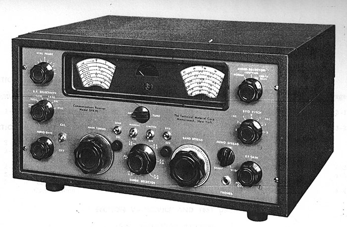
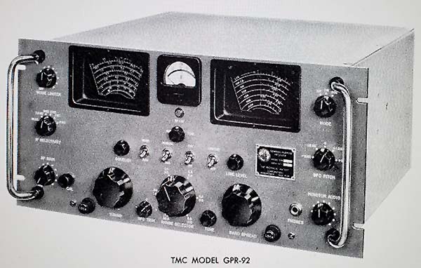
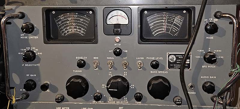
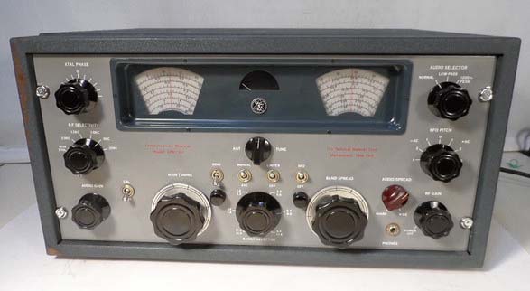
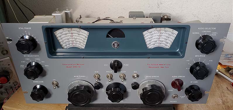
2.
GPR-90 tuning system uses "Pinch-Wheel"
drives - The
Hammarlund Super Pro Inspiration - The WWII Hammarlund Super Pro
seems to have been the "model" that TMC chose for designing the tuning
system used in the GPR-90. The dial layout versus placement of the
S-meter follows the WWII Super-Pro and many of the Hammarlund HQ-models.
The pinch-wheel, rim drive dial tuning system, including the dial
guides, are exactly like those used in the 1935 to 1949 Hammarlund
Super-Pro receivers (before the SP-600.) As to why TMC copied the WWII
Super-Pro in 1955 when it was obvious then that even the "new" Hammarlund
SP-600 was a "dated" design when compared to the receivers designed and
produced by Collins, is a mystery. It does seem like the TMC mechanical engineers
were copying designs that were already two decades old,...but, certainly
the cost factor must have been an important consideration on TMC's part.
But, even Hammarlund never changed their dial drive system on the Super
Pro from 1935 up through the 1947 SP-400-X shown to the right. |
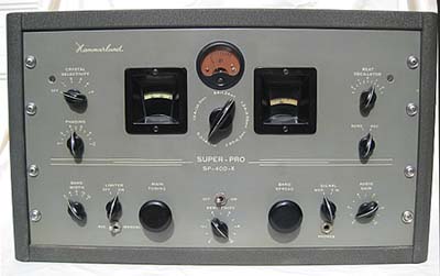
Hammarlund - Super-Pro SP-400-X |
|
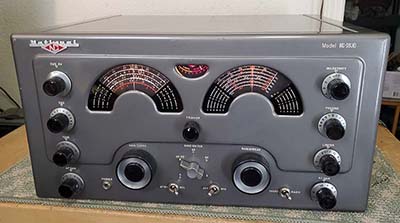
National Co. - NC-183D |
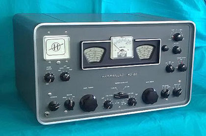
Incidentally, the National NC-183D also used a pinch-wheel rim-drive
tuning as did the Hammarlund HQ-180,...probably because when all of the
parts are in good condition and clean, this design results in very
smooth tuning and an excellent tuning ratio reduction in the drive. In
fairness to the NC-183D, those are edge-illuminated Lucite dials mounted
to copper-plated metal backing plates and the pinch-wheel actually works
against the metal backing plate that then drives the main or bandspread
tuning condensers through a gear-reduction set up,...a first
class mechanical design. While the NC-183D certainly won't win
any "beauty contests," it's no slouch when it comes to
performance. And, the NC-183D has one of the best audio
reproduction circuits found in a communications receiver. But, an
additional benefit was the selling price of just $385 in 1954.
The price did increase into the $400 range by the late-fifties.
On the downside, a lot of NC-183D receivers seem to have had
their original power transformers replaced with non-OEM units. |
|
Another direct-to-plastic dial "pinch-wheel" drive
tuning system with the two dials flanking the S-meter that was
contemporary with the GPR-90 was a creation
from National after they had changed their receiver manufacturing name to
"National Radio Company." That receiver was their cheaply
made and grossly over-priced NC-400. Without a doubt, the GPR-90 was a
better-built and better-looking receiver that could easily
out-perform National's NC-400 and only cost half the price. And,
when it came to "ugly," the NC-400
had few peers.
The Hammarlunds, the NC-400
and TCM all used a pinch-wheel to drive the rim of the plastic dial rim
directly. Dial warping and delaminating were sometimes problems on the pre-WWII designs but
post-WWII plastics were much better at resisting warping or other issues, so it's
usually not a problem to drive the plastic rim directly on these later
receivers.
3. Sunburned Dials?
- Although the plastic used for the dials pre-WWII was
particularly photo-sensitive and darkened with exposure to
excessive light, after WWII the plastics were much more
resistant to "sunburn." Normally, the GPR-90 dials won't
discolor from moderate exposure sunlight.
However, I did recently
inspect a GPR-90R receiver that had a very noticeable tan discoloration that was
limited to the portion of the dial that had been exposed to excessive sunlight
through the dial bezel opening. This discoloration was on both the main
dial and the bandspread dial. It's a seldom seen problem on the GPR-90
receivers,...but it
can happen. |
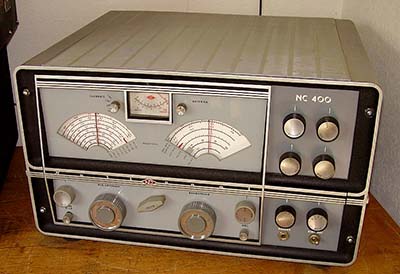
National Radio Co. - NC-400 |
|
4. TMC's Defense Regarding
Tuning Accuracy - TMC seemed to get somewhat irritated
whenever the GPR-90's tuning resolution was criticized. TMC actually
published testy comments in their service bulletins (SUP-1 GPR 9-56) defending the variable-C
tuning with analog dials against the "to the kilocycle
accurate" Collins tuning systems. The TMC arguments were, "The
GPR-90 is a general coverage receiver, and a real good
one, but it is NOT a frequency meter." This was followed by,
"People who require frequency meters should buy frequency meters - not
make them double as communications receivers." These are certainly the best known
of their peevish comments that all seem to be directed precisely at TMC's
"big-time" military contract competitor, Collins Radio Company. However, TMC's comments do illustrate that when
comparing the GPR-90RXD to the Collins R-388 in an unbiased evaluation,
maybe there's something to be considered besides tuning accuracy. TMC
probably thought that really ALL the R-388 offered the end-user
was essentially a frequency meter that happened to also work as a
receiver. Beyond the R-388's front-end, the rest of the receiver's
circuitry is standard and in some places actually deficient in
performance, e.g., the detector, the AVC, the noise limiter and even the
audio quality. So, maybe if the R-388 was looked at "critically" then
TMC probably had a point in their "frequency meter" comparisons.
Nowadays, 65+ years later, when vintage equipment from either company
can be easily found, rebuilt and used, we have a different perspective
on vintage receiver performance and TMC's comments advocating buying a
heterodyne frequency meter to go with your GPR-90 receiver seems kind
of humorous,...although I don't think it was originally intended to be.
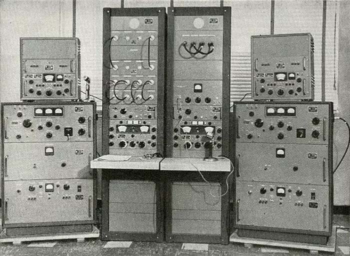
As an aside,...Beckman/Berkeley must have taken TMC's "freq meter"
comments "to heart" because one of their products was an elaborate
Beckman Frequency Measuring System that
had a Collins 51J-4 receiver (Beckman/Berkeley Model 7700) as the main component of the instrument.
The Beckman Frequency Measuring System is shown in the photo to
the right. Beckman extensively modified the 51J-4 to work with the
ancillary equipment in the system. Additionally, a new front
panel was made for the receiver. Note that the 51J-4 receiver
doesn't have a CALIBRATE function (100kc crystal oscillator.) |
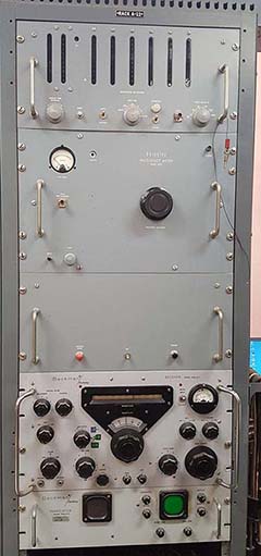
Beckman Frequency Meter |
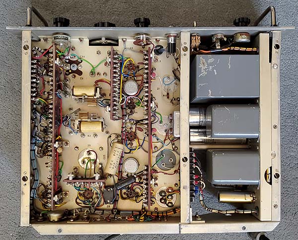
5. Cheap Construction?
A Mechanical Design Flaw or two? - This appears to be a common complaint but most reviewers are comparing
the GPR-90 to other more expensive, built-for-the-military (or
government) TMC products or to other expensive
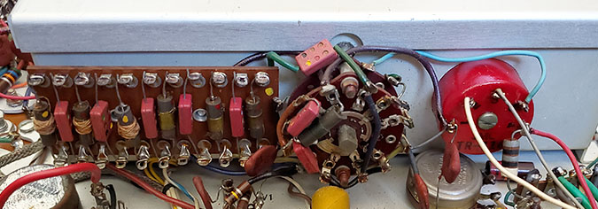
Collins military receivers. Hardly a fair comparison. The passive components used in the GPR-90 receivers appear to be excellent quality. Ceramic disk capacitors
are used throughout the receiver circuitry. A-B resistors are used
throughout. Component boards are used in
a few locations to reduce chassis component congestion and to provide a
better mounting platform for the circuitry. The build quality seems
to be better than average if the GPR-90 is actually compared to
other $400 to $500 receivers built for the ham market. That price would
put the GPR-90 mid-way between a Collins 75A-4 on the high end (about
$695) and a National NC-183D on the low end (about $385.) The GPR-90
sheet metal fit and finish are quite
good with the exception of the mounting of the AUDIO SELECTOR switch
housing that's behind the front panel. Typically, the shield-can will
interfere with the rotation of the bandspread dial. A slightly askew
mounting of the can usually will provide enough clearance (I did see
one GPR-90 that had the shield-can entirely removed.) It's also
possible that the AUDIO SELECTOR switch barrel won't be long enough to
fit through the rack mount panels that are slightly thicker and the
mounting of the AUDIO SELECTOR switch also has the side panel
wrap-around adding another .060" of thickness. The standard GPR-90 has a
slightly thinner front panel and doesn't usually have this particular
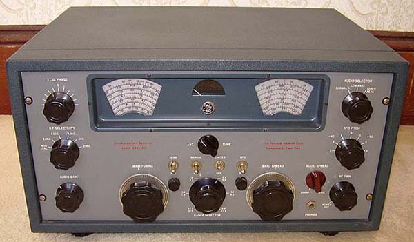
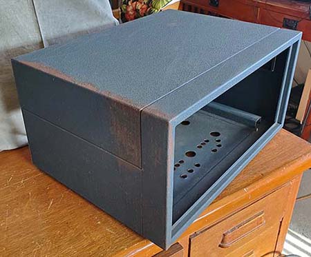
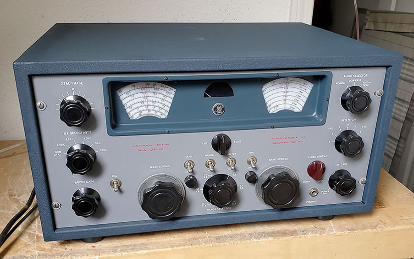
fit-problem. The GPR-90 table cabinet is steel construction, very heavy
(about 25 pounds) and painted a gorgeous medium blue wrinkle
finish paint (of
course, that's an opinion, isn't it?) The cabinet has a very low
height compared to the usual 1950s cabinets. The next mechanical problem is more
serious,...
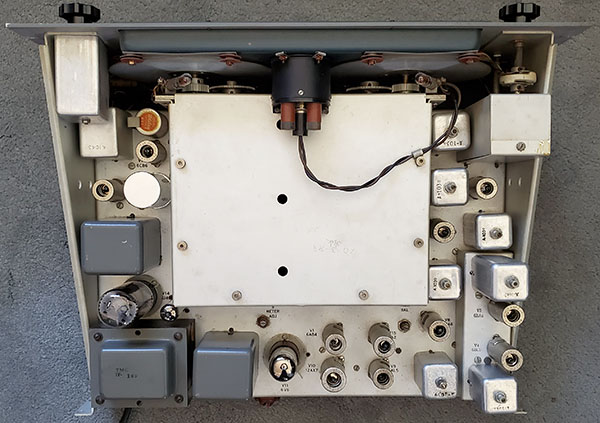
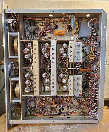
6.
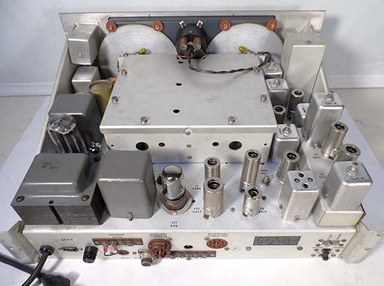
IMPORTANT NOTE about Potential Coil Form Damage:
This damage isn't specifically mentioned in Internet reviews but the
ceramic coil forms used in the GPR-90 front end are fragile and can be
easily broken. When the GPR-90 is removed from its cabinet for repair or alignment,
it's very important to first place the receiver chassis on its side.
Then check the RF coil box under the chassis to examine how far any of the
L-slug adjustment threaded rods protrude through the holes out past the
surface of the RF
coil box cover. This cover is usually flush with the height of the
chassis but the front panel does extend below the chassis line. If the
receiver is placed on a workbench right-side up with the front panel
bottom edge also on the workbench there is usually sufficient
clearance for the L-slug rods since there is some chassis elevation from
the front panel bottom edge being slightly higher than the bottom
chassis line.
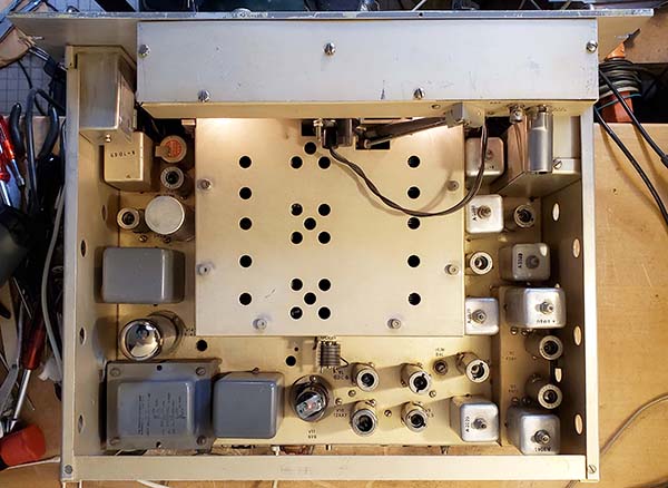
However, the result of placing the receiver chassis on the workbench
right-side with the front panel "hanging over" the workbench edge might
cause interference for any L-slug rods that protrude out the coil box by
putting pressure from the chassis weight directly on any
protruding L-slug adjustment rods. This can easily break the fragile ceramic coil forms
inside the RF coil box. Sliding the chassis onto the workbench can be a
disaster for any protruding L-slug rods and their associated ceramic
coil forms. If some of the L-slug adjustment rods are extending through
the cover holes then the chassis will have to set with either the front
panel bottom edge on the bench, but it's better to use some spacer
blocks to elevate the chassis off the workbench surface to protect the ceramic coil forms from damage when it's
right-side up on the bench. When the GPR-90 was new and aligned
correctly, none of the L-slug adjustment rods protruded out
through the holes but after decades of questionable maintenance, sloppy
alignments and
possibly
component aging sometimes a few of the rods will be protruding. Check
to be sure where the L-slug rods are before setting the chassis onto the workbench right-side up.
NOTE: Gerry O'Hara
VE7GUH, in his GPR-90 write-up, mentions the possibility that when the
chassis is either removed or replaced into the cabinet that the L-slug rods
could catch on the lip of the cabinet and cause the damage to the
ceramic coil forms. A link to Gerry's article is provided at the end of
this write-up in "References."
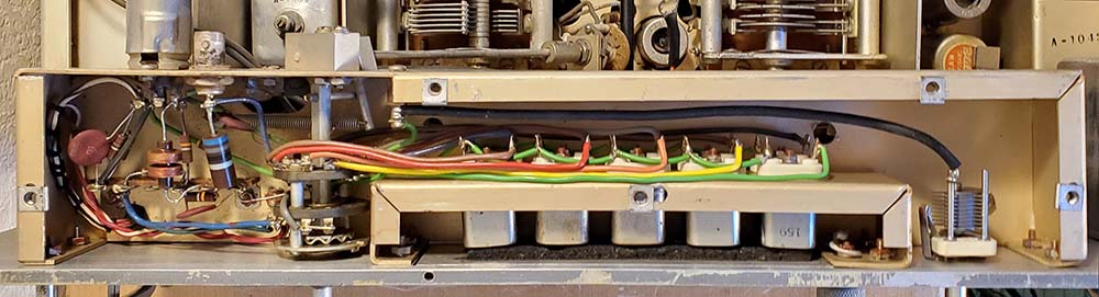
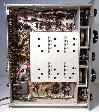
7. Mechanical Maintenance and
Disassembly Issues
- This isn't mentioned in the Internet reviews but if and when any type of GPR-90 receiver is extensively disassembled it
becomes apparent that maintenance wasn't at the forefront of the
mechanical design considerations. The TMC mechanical engineers seemed to believe the receiver
would NEVER need to be disassembled for any reason. Almost all assembly
uses screw, lock-washer and nut mountings and then the fasteners are
coated with GLPT. No pem-nuts are used and only the front panel bezel
has its screws threading into tapped holes. Top and bottom coil
box/tuning condenser covers are mounted with machine screws threading
into clip nuts. Additionally, some of the wiring assembly technique used very tight lead wraps that
were generally at least two
full wraps in, through and around the terminal eyelets. This makes any
defective component removal much more difficult than it should be with the possibility of
collateral damage also occurring (this is assuming the technician
isn't just going do a "clip and wrap" job.) This
electronic assembly technique, along with excessive torque used during
the mechanical construction, results in a receiver that's difficult to
disassemble without inflicting some collateral damage (one time I actually
broke the tip off of a "ball-tip" Allen wrench trying to loosen a
GPR-90 bandswitch knob set screw,...unbelievable.)
8.
Crystal Filter Not Selective Enough
- This is another common complaint that seems rooted in comparisons to
either modern receivers or to receivers equipped with Collins mechanical
filters. The GPR-90 Crystal Filter is the only control that the
operator has over the bandwidth. One has to wonder if the reviewers
actually adjusted the PHASING control for minimum bandwidth or
heterodyne attenuation or if they just expected that the bandwidth
showing on the switch nomenclature just "happened." Like any
standard Crystal Filter, the GPR-90's can also eliminate adjacent
frequency SSB "chatter" quite well but one does have to adjust the
PHASING somewhat off of minimum bandwidth to accomplish that. The NON XTAL position will have about 7kc
bandwidth at -6db. There are also a couple of audio filters that can be
utilized, one for voice operations and one for CW operations. On the whole, the GPR-90 is a little better
than most of its similarly priced competition for selectivity options (and
at least it doesn't have a Q-multiplier for a selectivity control!)
9. Not Mechanically Stable
- Another common complaint that certainly does have some merit,...but then,
how many people bang on the side of their receiver just to see what
happens? At any rate, there are a few things that contribute to the
mechanical instability issue and that would be that the coils mount on and
under the chassis directly below the tuning condensers that mount on the
top of the chassis. Any flexing of the chassis will skew the tuned
frequency by the mechanical movement of the LC involved. It's a common
problem in ALL receivers that are variable-C tuned with L coils mounted on
common chassis. When the receiver was mounted in a communications rack,
there wasn't access for the operator to reach in and "flex" anything, so
it's kind of a mute point when the receivers were properly installed and
properly used (and there are dial locks on both dials that could be
utilized.) However, mechanical instability problems that are
abnormal
can usually be traced to the "all too common" maintenance
technician practice of not
installing all of the shielding and not installing all of the screws,
washers and nuts. Mechanical stability did require that all of the
assembly mountings were secure and tight. Leaving
out screws (and even leaving out shields and covers) was a common occurrence with some types of maintenance
technicians. Also, component replacement soldering problems can be a
cause of instability. The receiver is assembled in such a manner that
component replacement is difficult to do correctly. Some technicians
would just "clip, wrap and solder" to replace defective components
resulting in sloppy-looking and operationally-questionable solder joints. Wholesale
capacitor replacement isn't necessary on the GPR-90 because of the
ceramic disk capacitors used but the filter capacitor and a couple of
the other electrolytics might have installation problems. Also, it was
common to have to replace the power transformer and proper soldering
with that installation would be very important. So, there
are lots of ways to create your own mechanical instability problems.
Also, sometimes instability can come from very simple problems that can
easily be solved, like just cleaning the variable-Cs, the bandswitch
contacts, the tube sockets contacts, etc. When
in excellent condition, with minimal mechanical wear and with a
competent going over of what really needs to be rebuilt or
replaced, the GPR-90 is as stable as,...say,...the Hammarlund HQ-180 or the
National NC-183D.
10. Demodulating SSB
Signals can be
Difficult, Maybe Impossible - A common complaint mainly from users that
expect to find a Product Detector in the GPR-90 receiver that would allow the
operator to have the RF Gain at maximum and the AVC on and demodulate
SSB signals with low distortion. But, the standard GPR-90, even with its
diode detector, can demodulate SSB
signals easily but it requires a reduction in the RF Gain level to
achieve the proper ratio of signal level to BFO injection level at the receiver
detector (also AVC can be switched off for better adjustability.)
Demodulating any SSB signal is easy so no particular difficulty
should be encountered IF the receiver is functioning correctly. The standard GPR-90 circuit uses a 15pf BFO
coupling capacitor and that is a large enough value to provide a good level of BFO
injection. The GPR-90RX receiver uses the same BFO circuit as the
GPR-90, so the BFO coupling capacitor is 15pf. The GPR-90RX will
demodulate SSB with the same ease as the standard GPR-90. This isn't the
case with the GPR-90RXD,...
For a "stand alone" GPR-90RXD, with its very low level of BFO injection, tuning in
almost any SSB signal is very difficult, maybe even impossible since the BFO coupling capacitor is just 3pf.
Even reducing the RF Gain doesn't help because the receiver becomes
desensitized before the received signal level to BFO injection is correct. The
only method for SSB reception with a stock GPR-90RXD is to use a MSR SSB
Adapter. It's possible that TMC intended that all
GPR-90RXD receivers that weren't in diversity set-ups would be set up with MSR SSB Adapters and therefore
the low-level BFO injection in the receiver didn't matter since all CW
and SSB signals would use the MSR adapter. It's also possible that the
low BFO injection level may have had something to do with diversity
reception and the receiver's BFO might have only been used for testing
and multiple receiver balancing set-ups for diversity operations. In all normal diversity reception,
regardless of the mode, the
receiver's BFO would be off and the receiver's AVC would be on.
Reducing the level of RF gain to adjust the ratio of signal input
level to BFO injection was standard procedure for CW reception
with almost all
superheterodyne communications receivers, from the 1930s up into the early-1950s. When SSB signals came along in the mid-fifties, this adjusting the BFO
injection to signal level ratio also applied to demodulating the "new SSB
signals." At that
time most
hams still had older receivers with diode detectors so to get the proper BFO
ratio they reduced
the RF Gain so the SSB signals would demodulate correctly. Some hams
went further and upped the BFO injection by increasing the value of the BFO coupling
capacitor. Later, modifications for a product detector to replace the
diode detector came on the scene. Although the standard GPR-90 doesn't
really have any difficulty demodulating SSB signals, the standard GPR-90 manual (in Section
7) suggests that the value of C59, the BFO coupling C, can be increased for better SSB
demodulation. I haven't changed the 3pf BFO cap in my GPR-90RXD
because it came with its
matching (same serial number) MSR-6 SSB Adapter. The MSR-6 (or any
compatible TMC SSB Adapter) makes all the difference in copying SSB
or CW
effectively with the GPR-90RXD. The MSR provides another IF conversion (455kc
to 17kc) along with a product detector and
its own BFO.
More details on the MSR-6 further down this article in the "TMC SSB
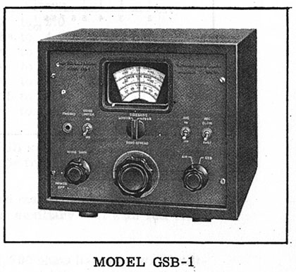
Adapters" section. The GSB-1 SSB Adapter would also provide a nice improvement
in SSB and CW reception capabilities for the standard GPR-90 with the
additional IF conversion of 455kc to 17kc, its own BFO and a product
detector. But the
GSB-1 is a rare and expensive (and not essential) accessory for the standard GPR-90 (even
the USN CV-591A SSB Adapters are now selling at about the same price as a R-390A receiver!)
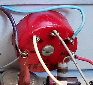
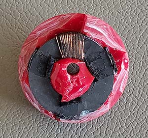
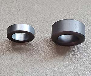
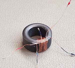
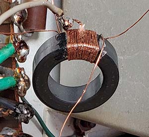
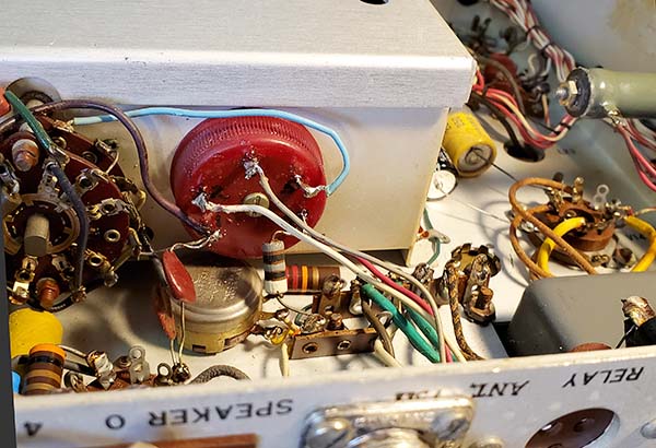
11. The
Ferrite Core Z-matching Transformer - The GPR-90's Achilles' Heel
- This isn't mentioned in Internet reviews so maybe it's just me. It seems that a large number of GPR-90
receivers are either missing the Z-matching antenna input transformer or
the one that's still in the receiver is defective. Unless there's some
protection provided to the antenna input, any RF, even from a relatively
low power transmitter, or a powerful pulse energy field (near lightning
strike,) getting to the 75Z or 300Z inputs will have a direct path
through a few turns of #30 magnet wire to chassis-ground. An
arc inside a misadjusted Dow-Key relay could provide sufficient RF to
overheat the Z-matching transformer windings which changes the
characteristics of the wire and the relationship of the primary to
secondary. This can result in either an open circuit primary or a
shorted primary to secondary. A nearby lightning strike might also
provide sufficient energy to overheat T1 with similar results. Large
array antennas in dry wind storms can generate very high levels of
static charges that might cause problems over time. One also has to
consider that the damage to T1 could be the result of multiple events of
a smaller magnitude over a relatively long time period that
accumulatively result in burned windings and a defective T1. Many other destructive scenarios can
certainly come to the imagination when the station antenna, when not in
use, is always left connected to the receiver input.
Of course, TMC expected that the ham
user would provide a T-R switching arrangement that protected the
antenna input circuitry in the GPR-90 since there isn't any antenna
input isolation provided in the receiver's design. TMC expected that the
ham installation would not only disconnect the receiver antenna input
but also ground the receiver antenna input upon transmit. The later
style DowKey coaxial relays provided a spring-loaded disconnect inside
the receiver-side SO-239 barrel to provide additional receiver isolation
upon transmit. But, for other types of energy sources, DowKey relays (and most other types of coaxial
antenna relays) didn't provide any isolation when the relay wasn't
energized, that is, in the receive mode. This "receive mode" was the
normal "power off" position for the typical ham station and it provided
a direct path for some types of antennas through the GPR-90's T1 to
chassis ground. Most hams knew that entirely disconnecting the equipment from the antenna and then grounding
the antenna (when the station wasn't
being used) was the best insurance against lightning damage.
However, from the quantity of damaged receiver antenna input circuits
found today, this type of protection seems to have been generally
ignored by many amateurs in the past.
What is unfortunate is that when T1 is "fried," the
receiver might still seem to function okay. An
inexperienced seller might even list the receiver as working fine. The
problems experienced with a defective T1 are subtle in some modes of
reception,...the AM mode with AVC on, RF at maximum, for instance.
However, in the CW or SSB mode, a defective T1 becomes very apparent. In checking out a
prospective GPR-90 purchase, if possible, measure the isolation between
the primary and secondary windings of T1 and measure the winding's DCR
to verify that it will function correctly. However, many times you won't
have the opportunity to measure T1's DCR because it won't even be there but will be entirely missing. Luckily,
T1 wasn't used in the GPR-90RXD versions of the receiver. However, I do
have to mention that even my RXD had Band 3 RF transformer's primary winding
"burned open" so putting destructive energy into a receiver's antenna input
does seem to happen a lot more often than one would think. One has to
keep in mind that these receivers are 65+ years old and a lot could have
happened to them in that length of time.
12. Extensive Use by Commercial Users
and Reworked by Hamsters - This isn't specifically
mentioned on the Internet but it is implied by some of the reviews. How
a receiver was used and maintained in the past can result in a litany of
problems after 60+ years of existence on the Planet. Many GPR-90 Series
receivers have extensive wear, especially those receivers used
commercially or by the military. Many of these types of receivers were maintained by
commercially employed technicians that had no regard for the equipment they were
employed to maintain. Many receivers were virtually destroyed by commercial
technicians with various types of rush-job, hacked repairs or non-engineered mods
that were for specific needs at the time by the end-user. Many of the
shields and top covers along the screws that mounted them were removed and
discarded. Many of the receivers, after surviving the gauntlet of
commercial technician maintenance, went on to ham ownership. That
sometimes ended up with the receiver being worked on by avid readers of
CQ magazine (nowadays, Electric Radio magazine) who were ready to
install the latest unvetted modifications published in the magazine
thinking that the mod will "solve all problems." Many of the hamsters
lacked any electro-mechanical ability but always seemed eager to modify the receiver rather than
actually repair it correctly. Also, hamsters always seemed eager to drill and
"hack-in" a non-original receptacle rather than
simply change the plug on the cable or accessory they wanted to use. So,
expect to find non-functional modifications, or maybe RCA phono jacks for antenna connections, speaker connections and
other circuit access points or Cinch-Jones receptacles installed just to
make it difficult to "de-mod" the receiver. The upshot is not too many of the
commercial GPR-90 receivers
have survived in operational condition, let alone in original, pristine
cosmetic condition. Some will be found that
have been competently rebuilt, look great and function to specifications,...but many others will be
non-functional, worn-out "hack jobs." To a certain extent, this
has led to impetuous judgments being made on receivers that haven't been
serviced in decades and certainly have corrupted circuits,
worn-out or broken components, possible wiring errors from mod installations and environmental contamination ingression from poor storage
conditions. The GPR-90, that is, not the RX, RXD or other
commercial-military models, being that it was a ham receiver, might have faired much better overall.
This would mainly be because the ham receivers
weren't subjected to the
rigors of commercial-military use or those types of maintenance programs. Naturally, it depended on the
ham owner,...and, after
nearly 70 years, there have probably been a lot of those. But, typically
the GPR-90 will be found in better physical/cosmetic condition than any of the
commercial-military variants. A ham-owned GPR-90's "electronic condition"
though is another matter.
13. Power Transformer Failures
- This wasn't one of the Internet complaints but something I've noticed
in examining many GPR-90 receivers. Most of the replacement power
transformers were installed in commercial or military versions of the
the GPR-90. That would be the GPR-90RX and RXD primarily, but I've also
seen a replacement power transformer installed in a GRP-90R receiver.
The conclusion drawn would be that since the standard GPR-90 receiver
was a ham receiver it wasn't normally operated 24/7 and, therefore, if
there was a component failure, it was immediately noticed and the power
shut off so the power transformer never had a chance to over-heat and
fail.
However, the commercial-military receivers were operated long hours,
perhaps 24/7. They were commonly left unattended for long time periods while still powered up.
This appears to have taken a toll on the power transformers due probably
to the transformer over-heating possibly from a component failure that
wasn't noticed for several hours. So, inspect any "prospective-purchase" RX, RXD, R
and any other GPR-90 version that was intended for commercial-military
operation,...you'll probably discover that the power transformer has
already been
replaced (or it might still be defective.)
14. Manuals - Again,
Internet reviews don't mention the TMC manuals. The GPR-90 manual is just
okay since not a lot of information is provided. The circuit
descriptions are very basic. The installation and operational guide are fine with lots of drawings. Voltage and resistance
charts are provided. Alignment information is fine. The biggest problem
is that no under the chassis component identification or location is
provided, not even a photograph. TMC does provide a slight hint at a component's
location with a brief notation in the parts list in the column "Function
& Location." For example, looking at C11 the notation is "Cathode
Bypass" and "V2" for the location. I guess it's better than nothing at all. The GPR-90RXD manual
is much more detailed, probably because the receiver was
commercial-military in its expected use. There are several enlarged
schematics that show just certain sections of the circuit that are used
along with a better, more detailed circuit descriptions overall. Still, although there
are photographs of the top and bottom of the chassis, none of the small
individual component locations are identified. Even the "Function &
Location" in the Parts List is reduced to just "Function." You're on
your own to trace out the wiring versus the schematic to locate any of
the individual small components. Interestingly, the
CV-591A/MCR-4 manual has the components that are mounted on the numerous terminal boards
identified. However, individual small components under the chassis
aren't identified in this manual either. Although all of the TMC manuals are pretty good,
don't expect totally complete information,...but that's typically the way most
equipment manuals are anyway.
15. Conclusions - I've
used the GPR-90 and the GPR-90RXD on-the-air several times over the
years. Although
this is on-the-air operating on 75M where almost any receiver has the capability of
providing decent reception. The challenge on 75M is to provide enough selectivity to have the ability to copy weak signals through the noise and QRM. I've found that
the Crystal Filter is a major factor in being able to use the GPR-90s as
a ham receiver. The audio is very nice for AM and the receiver's ease at
being able to set up the remote standby is a big help. So, the GPR-90s can
be used successfully in a vintage ham station provided you operate
mainly on 75M in the AM mode. I'm sure 40M wouldn't be a problem either. 20M through
10M signals seem just fine but I've never operated a GPR-90
on-the-air on those bands,...just in the listening mode,...and in that
mode the receivers do fine up into
the 10M band. BUT, "doing fine" is a judgment based on
comparison to other 1950s vintage receivers, not to modern transceivers or SDR receivers.
|
Finally,...Things to Keep In Mind When Operating
a GPR-90
A. - Is the GPR-90RXD really incapable of receiving SSB? Do you have to "ride the RF
Gain" for both CW and SSB when using the GPR-90? Yes,...to
both questions. The standard GPR-90 and the GPR-90RX
will demodulate SSB quite well as a "stand alone" receiver but, with the GPR-90RXD, demodulating SSB
is almost impossible,...unless you have one of the TMC
CV-591A/MSR-4, MSR-6 or other 455kc input SSB adapters. These SSB Adapters make ALL the DIFFERENCE in
being able to successfully listen to all types of SSB or CW signals with
the RXD. The
GSB-1 will provide a very low distortion SSB signal from the GPR-90
since it has a product detector but the GSB-1 isn't an essential accessory since the GPR-90 (and the GPR-90RX)
have sufficient BFO injection levels to allow demodulating SSB signals
by a slight reduction of the RF Gain level.
B. - Do you need to use a matched or resonant antenna for best performance?
Yes, especially with the GPR-90 because of its
ferrite core Z-matching input transformer. An untuned end-fed wire will
generally not provide either 75Z or 300Z at the antenna feed-point. For best performance, an
antenna matching device (antenna tuner) should be used to assure
that 75Z (or close to it) is what the receiver "sees" as the
antenna impedance. All communications receivers will
function best with a resonant (or Z-matched) antenna and an antenna with some gain is even
better, especially a yagi or a quad on the higher frequency bands.
C. - Does the GPR-90 f-Drift a lot?
Not really. The GPR-90
isn't the worst receiver for frequency drift but there
was a reason why the military wanted the RX and RXD versions
with the capability of a selectable Crystal Oscillator for the HFO. The
Crystal Oscillator
allowed f-stable reception for RTTY operation where f-drift can't be
tolerated. Like almost all vacuum tube receivers, the GPR-90 will drift rapidly for the first 10 minutes
or so as it
warms up but then it settles down
quite a bit after that. Drift isn't noticeable on AM operation. On CW or
SSB, f-drift is noticeable because those modes require the BFO for
demodulation and that adds
to the f-variability making drift more apparent. Also, the CW and SSB
modes are both extremely easy for the receiver operator to recognize
f-drift,...CW by the heterodyne tone change and SSB by the change in
voice characteristics. For the vintage ham
station operator, the GPR-90 is actually about as stable as would be
expected for an upper-end priced communications receiver. Something
that can't be said for the HQ-180, unless you leave it plugged
in all the time so the HFO and BFO tube filaments always stay powered on
continuously, even when the receiver is turned off.
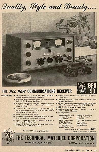
|
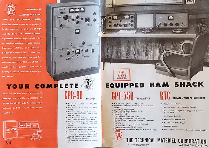
TMC's two-page advertisement in the 1956
ARRL Radio
Amateur's Handbook
No prices shown, you had to request the specific
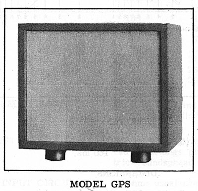
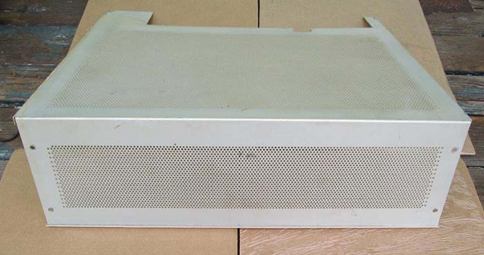
bulletin for that information. Note that the loudspeaker shown
with the GPR-90 is the GPS-2 version (same cabinet depth as the
receiver.) And another thing,...wasn't A2 (MCW) illegal on the
HF ham bands? |
|