Radio Boulevard
Western Historic Radio Museum


Broadcast Entertainment Radios

1922 to 1940


Compiled and Edited from the Former WHRM Photo Galleries:

"Roaring Twenties Radios"  ~  "Classic Thirties Radios"  ~  "Pre-War Console Radios"


Photo right: "The Arrival of Talking Pictures" with Oliver Hardy and the Radiola 24
(This scan is of an original photograph that I have.)   


Battery Sets  - 1922 to 1927


Westinghouse for RCA

RA-DA, RC

Westinghouse cross-licensed with GE/RCA in 1920, offering the Superheterodyne patent and the Regenerative Detector patent as their end of the agreement. Commercial Radio Broadcasting was about to start with Westinghouse's KDKA radio station located in Pittsburgh, Pennsylvania going on the air in November 1920. The first radio offered to the public for listening to the new broadcasts from KDKA was some gear that Westinghouse had built for ham market (radio amateurs.) The hams were less than enthusiastic about the RA and DA sets as ham receivers. So, lucky for Westinghouse, here was a new market for these sets - the Broadcast Radio listeners. These neophyte-listeners weren't nearly as critical as the hams were and the RA and the DA sold quite well. By mid-1921, Westinghouse had combined the RA-DA into one cabinet and designated this model the RC. The RC was produced well into 1922. Westinghouse also offered an Antenna Tuner (RT) and an RF amplifier (AR) in matching boxes, that is, matching the RA-DA.

The circuit uses three 1A pure tungsten filament tubes, a UV-200 soft detector and two UV-201 hard amplifiers. Early versions of the DA used WR-21 or similar tubes since the UV-200 and UV-201 weren't available until late-1921. Regeneration is via a tap switch (Tickler.) Performance is dependent on how good the tubes are. Pure tungsten filament tubes can't be rejuvenated and when the tungsten is exhausted of its ability to emit electrons, the tubes no longer function (even though they will "light up.") With good emission tubes the RC will perform adequately but it isn't very selective. This is due to the single-circuit tuner used. The addition of the RT and the AR improve selectivity and over-all performance. However, this "component" approach, while popular with enthusiasts, didn't appeal to the regular Broadcast listeners.


Westinghouse for RCA

Radiola Grand - Model RG

The Radiola Grand was the deluxe radio receiver from RCA-Westinghouse for 1923. Designed to replace the unsuccessful Aeriola Grand (with its ballast tubes and strange circuit adjustments - one had to pull tubes to lower the volume!), the Model RG was a great performer and its gold-plated hardware gave it that impressive, expensive look. At $325.00 in 1923 - it WAS expensive! Using four WD-11s, the circuit is a regenerative detector with single AF driver and Push-Pull output. Interstage transformers are used for coupling. Sound quality is excellent (for a battery set) using the built-in horn speaker. Note on the grille cloth: Originally RGs did not have grille cloth, however this brocade cloth was probably installed by the first owner or perhaps the dealer. Also, two styles of grilles were produced. The type shown is the later version grille.

The cross-licensing agreement with Westinghouse and General Electric (along with Wireless Specialty Apparatus, AT & T and RCA) was going to have GE provided 60% of the radios that RCA could sell. Westinghouse and WSA provided the remaining 40%. However, it took awhile for GE to get up to speed and most of the 1921, 1922 and 1923 radios were actually from Westinghouse. GE only provided the Radiola V and a few other models that were actually old shipboard radios that GE converted to look like consumer radios. Although GE had created RCA with their own assets and with the purchase of American Marconi (Oct. 1919,) GE decided to keep the American Marconi plant in New Jersey for themselves rather than let RCA build their own radios. This kept RCA under GE control, along with help from Westinghouse, throughout the 1920s. RCA didn't build any of their own gear for consumer sales. By 1924, RCA had purchased WSA from United Fruit Company and then continued to build shipboard radio equipment. In 1927, RCA formed Radiomarine Corporation from WSA and their recently purchased Independent Wireless Corporation. Things changed in the late-1920s with RCA acquiring many of their own patents and finally with their purchase of the Victor Talking Machine Company (purchased with the financial help of GE and Westinghouse in 1929.)

radgrand.jpg (18062 bytes)


Westinghouse for RCA

Radiola Senior Regenerative Receiver - Type RF

 Radiola A.C. 2 Stage Audio Amplifier - Type AC

The very popular, single tube receiver,  Aeriola Senior, was introduced in late 1921 for $65. By late 1922, it had been updated with a bakelite panel and mahogany box. Still later, in 1923, the name was changed to Radiola Senior (price was still $65.) A two-stage AF amplifier was an accessory to the Aeriola Sr. and also to the later Radiola Sr., also priced at $65. The 2-Stage Audio Amplifier added enough audio gain that a horn speaker could be used on most of the stronger signals, thus allowing the entire family to enjoy "the radio." The Aeriola and Radiola single tube, regenerative receivers perform quite well and are easy to operate requiring only a single 1.5vdc dry cell and a 22.5vdc B+ battery, a set of earphones and a suitable antenna and ground. The tube normally used is a WD-11, however an 864 or WE239A will work equally well but will require the use of a socket adapter (WE-239A is shown installed in the Radiola Senior.) The AF Amplifier requires two WD-11 (or compatible substitutes) along with a set of dry cells for the filaments and a 60 to 90vdc B+ battery. The amplifier is shown with later type WD-11 tubes installed. The horn speaker was optional.


Federal Telephone and Telegraph Co.

DX Type-58

Federal built high quality receivers though some of their circuits and mechanical devices seem rather "Rube Goldberg" at times. The DX Type-58, from late 1922, was designed for the enthusiast and the metal cabinet seems to show this. Selling price was somewhat expensive for a four tube set - $123. Federal's workmanship was excellent, however their documentation is vague at best. It is interesting that Federal was so afraid of a RCA-Westinghouse law suit over the Regenerative Detector patent, they didn't tell owners (in their instruction manuals) that their radios could be set to regenerate and therefore significantly increase performance. Having "Regeneration" in print in an operator's manual would have been as good as an admission of guilt by Federal. Most owners figured out the adjustments anyway and the radios were fairly popular. By setting the "COUP" control to near "0" and advancing the "AMP" control to near the oscillation point, the DX Type-58 (and most other Federals) can be quite sensitive and selective receivers.

I've owned this DX Type-58 for a very long time. I purchased it from an electrical repair shop in Reno in 1975 (run by a guy named Max.) The price was $20 and the condition was terrible. I actually got Morgan McMahon of Vintage Radio to send me the dimensions for the lid from his DX-58. This DX-58 needed a reproduced brass lid and a reproduced brass back for the cabinet. Electronics included rebuilding the AF transformers and the RF transformer. Eventually, I did get the DX-58 working and even wrote an article for "Radio Age" about the restoration process.

type61.jpg (20956 bytes)

Type 61


Introduced in the fall of 1923 for an incredible $223, the Type 61 was Federal's high-end receiver, six tubes - three RF amplifiers with grid-bias controlled amplification running into the detector stage and two transformer coupled audio amplifiers. One could select either one RF stage or three RF stages, a loop antenna input or external antenna input. One could also select various audio amplification circuits and the second audio interstage transformer has a selectable ratio secondary. In all, sixteen different circuit configurations could be set-up, making the Federal Type 61 one of the most versatile battery receivers of its day. Though the manual is vague about the regenerative capabilities of the Type 61 ("regeneration" is never mentioned), performance can be excellent if the "COUPLING" is kept near minimum and the "RF AMPLIFICATION CONTROL" set near the oscillation point.


A. H. Grebe & Company

Broadcast Receiver CR-12

Alfred Henry Grebe was one of the very early radio builders. He was a very young teenager when he was building radios for neighbors and, by 1917, at age 22, he had a contract to build WWI submarine receivers. Grebe produced various types of ham equipment shortly after WWI ended and the "radio ban" was lifted (April 1919 receive, October 1919 transmit.) His earliest radios built before the 1921 "radio broadcast boom" were communication receivers for hams and some commercial users. This was the beginning of the "CR series" of Grebe radios that, while some are strictly for communications (the CR-7, for example,) many could double as broadcast receivers (the CR-9.) In fact, some of the CR sets were intended only as broadcast receivers, the CR-12, for example (it's labeled "Broadcast Receiver" on the front panel.)

Grebe always believed that the mechanical construction of a radio was just as important as the circuit design. Much of Grebe's advertising stressed this belief. Even the argument used in the Hazeltine lawsuit over the Grebe Synchrophase unlicensed use of the Neutrodyne circuit was that the mechanical design and construction gave the Synchrophase its incredible performance, not the Neutrodyne circuit (more details on the lawsuit in the Grebe Synchrophase section further down this page.) All of the CR series are well-built receivers but the circuits are not unique to Grebe. After all, he did have a 1914 Armstrong license to build regenerative detector receivers. That didn't stop Westinghouse from suing Grebe after they had purchased Armstrong's patent in 1920. At the time, Grebe stopped sending the payments to Armstrong and just sent the regenerative license payments to Westinghouse instead (and they just kept on cashing the checks.) Ultimately, that's what lost the case for Westinghouse. Grebe had paid the license fees and Westinghouse cashed the checks therefore Westinghouse must have agreed to the terms of the license deal. At any rate, Grebe continued to build regenerative receivers up into the later twenties, although most of these were for ham radio use.

The CR-12 is from 1923 and it uses four tubes. UV-199 tubes installed into regular bayonet-sockets using socket adapters was the intended tube lineup although 201-A tubes could also be used by removing the adapters. Small pull-switches next to the filament adjustments marked C1, C2, C3 and C4, if pulled out, would connect a parallel resistance to each filament adjustment that lowered the resistance (and increased the dissipation) to allow using 201-A type tubes. Pushing the switches "in" disconnected the parallel resistance to allow the lower current UV-199 tube filament operation. Each tube has its own filament current control. Tuning is accomplished using variometers rather than air variable capacitors. The secondary tuning is calibrated in meters along with the 0-100 scaling. Regeneration is accomplished by increasing the RF amplifier tube signal-grid input through varying the resistance of the variometer stator to B-/Ground. Additionally, the level of RF amplifier filament voltage will also affect the RF gain and the tendency towards oscillation. These two controls are adjusted until the RF stage breaks into oscillation, then the Regeneration control is reduced until the oscillation stops. This high-gain RF signal is routed through the coupling coil to the Detector tube variometer.   >>>

>>>   The combining of both tuned-regenerative RF amplification plus tuned input Detector gives the CR-12 excellent sensitivity and selectivity for broadcast reception. Since the CR-12 was intended as a "Broadcast Receiver" regenerative oscillation was a condition to be avoided. The proper setting for AM demodulation would have been just before the RF stage breaks into oscillation. The audio amplifier stages are standard transformer coupled circuits. The cabinet is much deeper than other Grebe CR receivers to allow two storage compartments for dry-cell batteries when using UV-199 tubes. 201-A tube filaments would require using a storage battery that had to be located outside the radio cabinet (holes for the external A battery cables were provided.) The B batteries would still occupy the other storage area. C bias is not used in the CR-12. The cabinet is constructed of solid walnut finished in lacquer. The panel is the standard Grebe CR finish which is grained bakelite giving it a flat black appearance. The CR-12 sold for $175 in June 1923.
 

Atwater-Kent
 MODEL 4560 - a.k.a. 10-B, "A-K Breadboard"

Arthur Atwater-Kent made a fortune in the automotive ignition and lighting business but moved into radio parts manufacturing around 1922. Initially, A-K offered various kinds of radio parts to build your own receiver. By 1923, complete A-K radios were being offered. A-K believed his manufactured parts were beautiful (and so do a lot of collectors) so exposing them on open boards seemed the logical design for his receivers. Initially, small receivers were offered but the radio market was "hot" so A-K enlarged the receivers up to five tubes using a standard TRF design. The first Model 10 was called a "Radiodyne" but within a couple of weeks, Western Coil informed A-K that they owned the Radiodyne name. A-K immediately stopped any use of the name Radiodyne on his receivers. There were several Radiodyne A-K breadboards sold so they do show up from time to time. The first Model 10 breadboards have terminals for connecting power but later sets used a battery cable.

Early Model 10s also have the RF coils mounted in the same axis but later this was changed to prevent coupling between stages. Most of the Model 10 breadboards were sold during the 1924 year. The last Model 10, the 10C, was a reduced size board with the components mounted much closer together. The 10C was sold in early 1925. Original selling price for the A-K breadboards was usually around $100. The TRF circuit provided good reception although the upper limit of the tuning was about 1200kc. Quality was top notch, as with all A-K receivers. Most models had both standard, or black wrinkle finish paint, or deluxe, brown wrinkle finish available. There are many variations and different models of breadboard sets that were made between 1923 and 1925. Shown in the photo above-left is the 1924, Model 4560 (A-K 10-B) in standard finish, (black paint on the cans.) I've owned this AK-10B since the late-1980s. It does work.

Harold E. Greenwood's and Morgan McMahon's  A-K 10B

Anyone that has been collecting antique radios for awhile has probably heard of Harold E. Greenwood. He is best known for his book "A Pictorial Album of Wireless and Radio 1905-1928" published by Floyd Clymer in Los Angeles, California in the early 1960s.

Greenwood was a radio collector who took the time to research and photograph much of his collection and other collections to compile his book. Another well-known radio collector was Morgan McMahon who published the book "Vintage Radio" which was based on Greenwood's original album. Vintage Radio came out in the early seventies and had almost everything in it that had been in Greenwood's book. McMahon also published a list of radio descriptions that had been complied by Greenwood. The manufacturers were listed along with all of the known models and included number of tubes, circuit, number of tuning dials, original selling price and more. This book was called "Radio Collector's Guide" and it was also available in the mid-seventies. McMahon then came out with "Flick of the Switch" that chronicled radios from the 1930s up to the 1950s. FOTS also covered some vintage ham gear and had a write up on simple radio theory and repair. These were great books that really helped antique radio collectors that were interested in manufacturing history and circuit types,...they weren't price guides. Shown in the photo above-right is an A-K 10B that was at different times owned by both Harold Greenwood W6MEA and by Morgan McMahon W6TPE (both Greenwood and McMahon-Vintage Radio stuck their name labels on the underside of the breadboard.) Photo left shows the cover of Greenwood's book.

TYPE TA - 2 STAGE AF AMPLIFIER

Shown in the photo to the right is one of Atwater-Kent's component parts that were being sold in 1922 and 1923. This is a two-stage, transformer coupled audio amplifier. Connections are via binding posts behind the tube sockets. The potentiometer adjusts the filament voltage on both tubes as a method to control gain or output level. Although the intended tubes were probably UV-201A tubes, this TA was found with two good condition WD-12 tubes installed. Early A-K cans were painted an olive-green color and some of the very early breadboard sets also have cans with this color paint applied. All of the later cans are either black or brown wrinkle finish paint.


General Electric for RCA

AR-812  Second Harmonic Superheterodyne

The AR-812 was the first production superheterodyne offered to the general public. Western Electric was producing commercial superheterodynes earlier and supposedly installed one in the White House. That "fired up" David Sarnoff, who was RCA's GM at the time, to have GE build a superhet for RCA to sell. As with many new types of circuits, the AR-812 prototypes didn't work very well with internally generated noise due to reflexing some of the circuits. Ed Armstrong was called in as a consultant and the problems were reduced to the point where the receiver could be offered for sale. RCA was aiming for Christmas 1923 but delays moved the release date to February 1924. The incredibly high selling price of $235 didn't seem to deter the radio enthusiasts and the AR-812 sold very well. It sold even better when the price was reduced and, by 1925, new-in-the-box, surplus production left-overs, were being sold for $10. The AR-812 did out-perform most of the competition and with a large indoor loop antenna, coast-to-coast reception was possible. Six UV-199 tubes are used and the receiver does have have a small built-in antenna. In fact, some of the advertising for the AR-812 promoted the receiver as being "portable."

The AR-812 uses what RCA called "catacomb" construction. Most of the receiver circuitry and components were contained in a metal box that is filled with hard wax. The external flexible wire connections were called "whiskers" for some reason. It is possible to determine faults in a catacomb by measuring the resistance between various whiskers. RCA provided the data and procedure for testing catacombs. However, RCA wanted the defective catacombs returned or exchanged for good ones when doing repairs. Not possible today, of course, and most restorers repair their own catacombs (if they want the receiver to function.) I use a second-hand toaster oven (usually a few dollars at thrift stores) set to 180F or so to melt out the wax. It will be necessary to carefully remove the lead seals to preserve the embossed "RCA" on them. Also, sometimes a vent hole has to be drilled to allow the heated wax to flow out. Once the wax is removed, repair is straight forward. You'll almost certainly find that some of the very fine wires used in the circuit have broken. This is probably due to expansion and cracking of the wax breaking the fine wires. Once the catacomb is repaired, you don't need to refill it with wax again. RCA used the wax as a method of keeping the superheterodyne construction secret or at least from becoming common knowledge to the technoids of the time.

The AR-812 shown in the photo was found (in 1993) in the upstairs storage rooms above the Crystal Bar in Virginia City, Nevada. The Kolster Loop Antenna (Federal Telegraph Company) and the RCA UZ-1325 horn-speaker were with the AR-812 and the radio had all six 1.5vdc dry cells still installed. The "station cards" are vintage and were penciled in with west coast stations. In the past, the radio had been operated using dry cells for the filaments and an AC operated "B eliminator" for the higher voltages. Just how long the radio, loop and horn had been upstairs is hard to say. Bill Marks, who owned the Crystal Bar then, was an avid collector of all kinds of antiques. The Crystal Bar was famous for its display of various kinds of orchestrons, nickelodeons and other types of mechanical music players. The upstairs was filled with other types of antiques including phonographs, radios and parts. Everything was eventually sold off when Marks died. The Crystal Bar is now the Visitor's Center for Virginia City operated by the VCCTA.

AR-812 with UZ-1325 Horn and Kolster Loop


Crosley Radio Corp.

Model XJ
 

Powel Crosley Jr. got into the radio business because his son wanted a crystal set. The prices were too expensive, in Crosley's opinion, so he bought a twenty-five cent booklet instead and built his first radio. Realizing how easy it would be to build and sell simple receivers, Crosley bought Precision Electric (in 1922) to begin his radio business and the following year formed Crosley Radio Corporation from Precision Electric. Crosley radios are noted for  good performance with inexpensive parts and cabinets. By keeping manufacturing costs low, Crosley was able to offer his radios at very low prices resulting in high sales. His methods of manufacture eventually led to his becoming known as the "Henry Ford of Radio." Crosley went on to owning BC station WLW, owning the Cincinnati Red Legs baseball team, building small cars and many other endeavors. Shown is a 1924 Crosley XJ, a four tube TRF receiver.


Crosley Radio Corp.

Model 51
 

One of the most common Crosley battery operated regenerative receivers is the Model 51. Crosley sold them for $25 and the little two-tube radio performed quite well. Certainly, the Model 51 shows what can be accomplished when the goal is to build a two-tuber (regenerative detector and one stage of AF amplification) as economically as possible. Crosley was already famous for their ultra-simple "book condenser" that replaced the expensive tuning condenser. The "tickler" was a push-in or pull-out type of control that allowed the operator to control regeneration by changing the proximity of the tickler coil to the secondary coil. A simple push or pull of the regeneration knob changed the position of the tickler coil behind the panel to adjust the regenerative feedback. Most of the other parts used in construction are standard for the period. The cabinet is made out of poplar wood and was given a very basic finish (probably just a coat of shellac.) It didn't matter how cheaply made the Model 51 was - it performed quite well, better than many other more expensive sets. Crosley sold thousands of the Model 51 for that very reason. The Model 51 was available from 1924 through early-1925. The Model 51 shown still has its complete original warranty card attached under the lid. The date on the card is interesting, Dec.25, 1924 - Christmas Day. This 51 is in "as found" condition.


R. E. Thompson Mfg. Co.

The Thompson Grandette - V-50

Roy E. Thompson worked in the Department of Commerce, then for Kilbourne & Clark before buying Wireless Improvement Company around 1917. He started R. E. Thompson Mfg. Co. to obtain a Neutrodyne license from the Independent Radio Manufacturers. The "Independent Radio Manufacturers" was formed by eleven companies who wanted to develop a radio that could compete with the GE-RCA-Westinghouse owned Superheterodynes. They approached Louis Hazeltine for the design work and the Neutrodyne was born. It used capacitive feedback in the RF amplifiers to cancel the tube's interelectrode capacitance which then allowed for higher gain in that stage without oscillation instability. The RF coils were physically oriented at 45 degree angles (tilting) or a 90 degree mounting relationship to reduce any stray coupling between RF stages. The Neutrodyne, when properly designed and manufactured was the best performing TRF radio receiver of the time. While it didn't always perform as well as a Superheterodyne, it certainly performed better than any other type of TRF receiver. Unfortunately for all other manufacturers, unless you were an original "Independent Radio Manufacturer", you couldn't legally build Neutrodynes (see "Grebe MU-1" below.)

The Thompson V-50 was introduced in October 1924. It is a well-built Neutrodyne using five tubes that consisted of two Neutrodyne RF amplifiers, Detector and two stages of audio amplification. Interestingly, the V-50 allows the option of either using the C- bias or not, all controlled by connecting or disconnecting a metal strap across the bias battery connection terminals. At the time, the only reason for using C- bias in the audio section was to prolong the life of the B+ batteries. Also, a "dummy plug" is installed in one of two chassis jacks marked "1" or "2" to select whether one or two audio stages are used for the output jack on the front panel. The Grandette V-50 styling is typical of the 1923-24 Neutrodynes, that is, black panels and three symmetrically mounted tuning dials. Inside the workmanship is first-class. Thompson also sold a matching horn speaker that featured a direct-driven conical diaphragm.

Thompson radios were high priced with the V-50 selling for $125 in 1924. Thompson radios looked like the typical Neutrodyne (e.g., the early FADA.) A few other manufacturers had models out there at half the cost of Thompson's least expensive models. Those cheap radios weren't Neutrodynes but most radio consumers didn't know the difference and were only concerned with the price of their intended purchase. Take a look at the early Freshman Masterpiece (which actually came out before the V-50) as an example of a radio that looked convincingly like the typical Neutrodyne but sold for only $60 (Freshman write-up below.)   >>>

>>>   To the radio-buying public, the Freshman was the better deal - until they got it home and found out how badly it performed. The Thompson V-50 would easily "bury" the Freshman in all areas of performance. Unfortunately, the new Freshman owners found out too late that they had been "taken" by Charlie Freshman.

Thompson's sales were never as high as expected and the company was in constant debt, despite introducing new models. By the end of 1927, Thompson was out of business. Interestingly, Charlie Freshman was also about to be forced out of his company. The days of selling "really cheap" radios were about to end with the introduction of lightsocket-powered radios - AC-operated in most areas, DC-operated in Edison-powered areas (rural areas still had to stick with battery operation.) Even a merger with Freed-Eisemann didn't help Freshman since the 1929 Stock Market Crash was right around the corner.


Chas. Freshman Company

Freshman Masterpiece & 5-F-4

Charlie Freshman entered the radio business at the right time, made a lot of money and then got out of the business to spend that money. Starting in 1922, Freshman began selling radio parts and then moved into fully assembled radios when the Neutrodynes started coming out (late-1923 for the FADA.) Designed to look like the typical Neutrodyne, Freshman's radio, the Masterpiece, sold for half the price at $60. If you wanted it as a kit, the cost was only $17. Freshman's engineers utilized the losses of mounting the RF stage inductance directly onto the metal frame of the tuning condensers to prevent the RF amplifier stages from oscillating. This was Freshman's approach, build as cheaply as possible. It worked, too. At its production height, Freshman was turning out over 1000 radios a day. Only after the novice radio buyer got a chance to listen to a neighbor's real Neutrodyne radio did he then realize how badly the Freshman Masterpiece performed. Reliability was also an issue with Freshman Masterpiece radios with defective interstage transformers and potentiometers being the worst offenders. As Freshman evolved as a business, his radios really didn't. New cabinets and different tuning dials maybe, but the circuits remained basically unchanged.  >>>

>>>  Freshman used a particularly high ratio interstage transformer that was not only unreliable but even when working provided so much gain that the audio distorted heavily. No -C bias voltage was used on most (all?) models. Most of the transformers used 6:1 ratio or even higher while the industry standard was 3:1. By 1928, Charlie Freshman was forced out of the company and Walter Chrysler infused some cash into a merger of Freshman and the Freed-Eisemann Company. While the Freed-Eisemann name was used for the high-priced models, EARL was used for the Freshman models. EARL lasted a year or so, until late-1929 brought on the Stock Market Crash.

Freshman made a lot of radios. While they are very common, it is rare to find one that hasn't had some repairs made to it. After all, the parts were just about the cheapest that Charlie could find. The upper right photo shows the typical 1924 Freshman Masterpiece. Supposedly, if the "Freshman Masterpiece" logo isn't present under the switch, then that particular set was the kit version. I've only seen one FM without the logo, so not too many buyers opt'd for the kit.

Shown to the left is the later version of the 5-F-4 model. Earlier versions had external dials while the later version have the dials behind the small windows. This model sold for $49 - really cheap. What is unusual about this particular 5-F-4 is that it is all original and functional. The distortion from the audio is unbelievable due to the 8:1 ratio interstage transformers with no -C bias. Even one of the contemporary radio magazines stated that Freshman's business relied on inexperienced buyers that eventually learned that they had been "taken" by Charlie.


The earliest of the Synchrophase receivers with no chain-drive and no Tone Color control - from late 1924. The initial Synchrophase only had one tuning range, tuning from about 500kc up to about 1300kc. In 1925, a band switch assembly was added that allowed for two tuning ranges allowing tuning from 500kc up to about 1800kc. The 1926 changes were for improved audio reproduction. The Synchrophase was produced from late-1924 up until April 1927. Estimated production is over 150,000 Synchrophases built in that time.

A.H. Grebe & Company

 "Synchrophase"  MU-1

Arguably, the Grebe Synchrophase is best performing 5-tube TRF AM Broadcast battery set that was made in the mid-twenties. The circuit was a Neutrodyne and Grebe was sued by Hazeltine (Independent Radio Manufacturers) because of it, though production of the MU-1 was never stopped and continued on, ultimately reaching over 150,000 radios. The MU-1 is very sensitive and will separate signals quite well due to its SLF (Straight-Line-Frequency) condensers and binocular coils. The construction of the binocular coils prevented an EM field from being radiated and eliminated stray coupling between the RF stages. The remaining interelectrode capacitance of the RF amplifier tubes was "balanced out" with feedback condensers (which Grebe called "Balancing Condensers.) Grebe engineers considered the MU-1 Synchrophase's great performance was due more to the design and construction of the unique precision components used in the receiver rather than the Neutrodyne circuit.

The earliest Synchrophase receivers use a single filament control and a volume control that selects various resistors that are across the second audio interstage transformer primary. The small round escutcheons only had "INCREASE" embossed on them. Shortly after "VOLUME" and "FILAMENTS" were added to the "INCREASE" on the small round escutcheons. These early Synchrophases only tune up to 1300kc. Several improvements were added in a mid-1925 production upgrade but the most significant improvements were the ball-chain drive for single-dial tuning and the bandswitch that allowed increasing the upper end of the tuning range to 1900kc.  The bandswitch was actuated by the center dial at either end of its rotation. The chain-drive could be disabled by loosening the knurled nut on top of each outer dial. This would not affect the operation of the bandswitch but allowed for more accurate tuning of the signals. Other mid-1925 additions or upgrades included a "TONE COLOR" control that was actually modified from the old "VOLUME" control. The "TONE COLOR" was now an adjustable resistive-capacitance device installed across the primary of the second audio interstage transformer. The "VOLUME" control was a modification of the old "FILAMENTS" control that changed the component into a dual filament control that separated the detector and AF filaments adjustment from the RF amplifier tubes adjustment, providing better response for receiver output.

A mid-1926 upgrade added an improved audio interstage transformer that increased the "low frequency" response to improve the sound quality. Also part of the 1926 upgrade was changing the audio output tube to a UX-112A, requiring an increased B+ of +135vdc and an increase in the -C bias to the audio output tube to -9vdc. Additionally, the "TONE COLOR" control was changed to a selectable capacitance that shunted the 2AF audio grid to -C. Somewhat after the mid-1926 upgrade a cushioned detector socket was added and, shortly after that, all of the sockets were changed to the cushioned-type. There were no other upgrades after the mid-1926 changes and the MU-1 continued in production until around April-May of 1927. Throughout production there were minor changes to the hardware and assembly, e.g., some sets are found with two lid props and some with just one. Additionally, the dial escutcheons were usually finished in lacquered gold but supposedly some MU-1s had gold-plated escutcheons. Front panels will be found with either linear faux graining or burl (mottled) faux graining. The instruction cards are found in various colors, cream with black letters, yellow with black letters and cream with red letters depending on the vintage of the set. To this day, Grebe's serializing of the Synchrophase remains a mystery. The serialized identification consists of four letters, e.g., "TFZH" or "BWDC", etc. - the letters were not chronologically arranged and defy any sort of decoding. It seems likely that the intent was to obfuscate the actual number of MU-1 receivers being built (at least by serial number inference) since that total built quantity might 
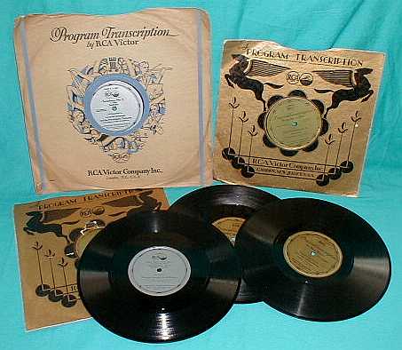
have figured in a settlement in the pending Neutrodyne suit. Included with the purchase of a new Grebe MU-1 were "Dr. Mu" QSL cards that allowed users to send reception reports to broadcast stations they received on their MU-1 (in the hopes of receiving a return reply QSL card from the BC station.) "Dr. Mu" was an advertising character that Grebe created - a fictitious ancient Chinese philosopher-scientist. "Mu" refers to µ or mu, the gain of a vacuum tube. 

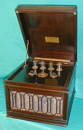
There was also an MU-2 available that was a dry-cell tube version initially using six UV-199 tubes. Later versions used four UV-199 tubes and one UX-120 tube. Another 
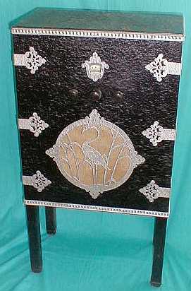
option was a Battery Base that the Synchrophase would set on top of. The Battery Base was designed  for the 1924 version of the Synchrophase that used four +22.5vdc B batteries. By mid-1925, two large +45vdc B batteries were now specified and these wouldn't fit into the Battery Base due to their height. Owners could still operate their 1925 set on the four +22.5vdc B batteries since the voltage requirements hadn't changed. When the 1926 version added the UX-112 tube with +135vdc B voltage the set now required three large +45vdc B batteries (beside two C batteries) and there was no way to fit all of the batteries in the Battery Base. However, by 1926, there were smaller +45vdc B batteries available that would fit into the base but their useful life was much shorter than the larger B batteries. Around this time, the Battery Base was rapidly loosing any desirability as an option. Due to the later battery requirements, most original Synchrophase and Battery Base combinations that turn up are the earlier 1924 to mid-1925 versions. Note that the cabinet feet must be removed from the Synchrophase cabinet in order for it to set flush into the Battery Box recessed area.

The court case regarding the Neutrodyne Patent infringement was heard in June, 1927. Grebe lost the case but was able to obtain a Neutrodyne license almost immediately. However by this time the MU-1 was obsolete and Grebe production was moving to single-dial receivers, the Synchrophase AC-6 and later the AC operated AC-7. The Synchrophase MU-1 production had run from mid-1924 up to mid-1927 and an incredible 150,000 receivers had been produced during that time. 

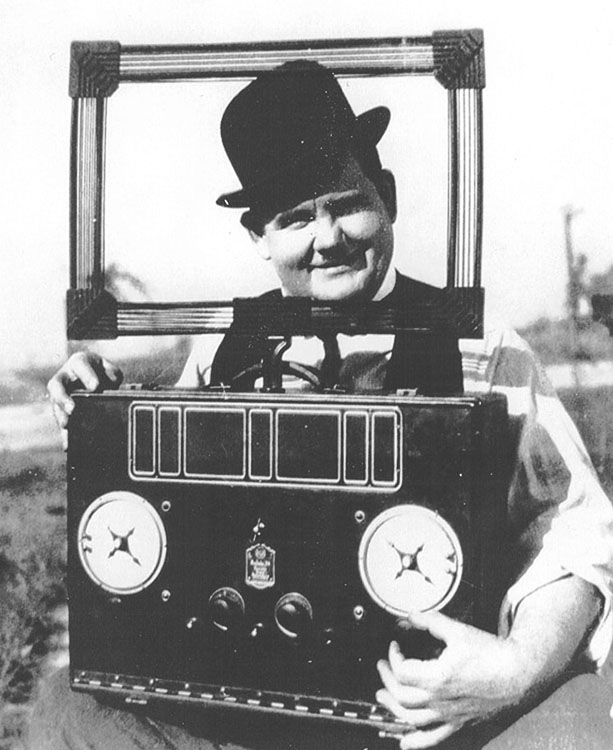
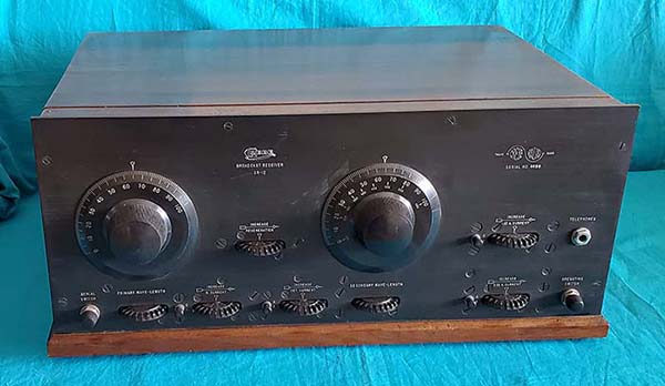
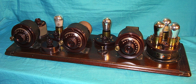
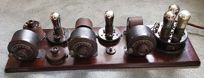
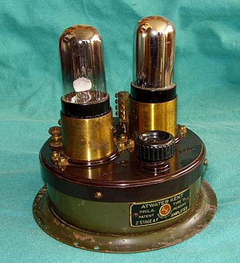
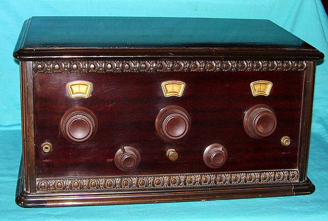
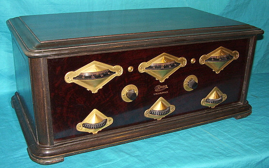
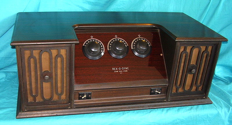
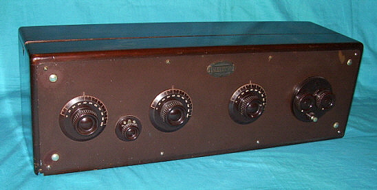
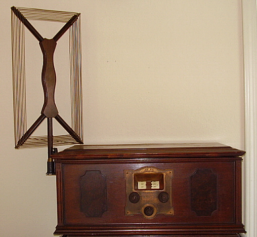
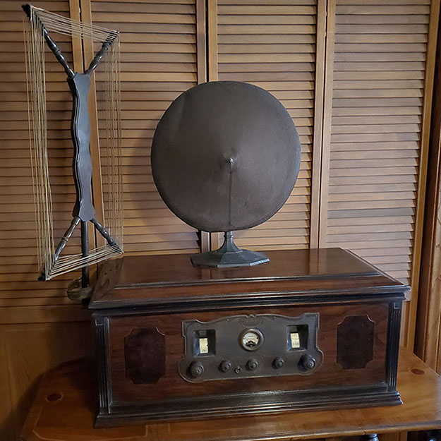
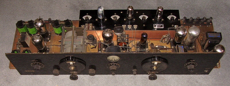
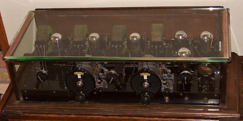
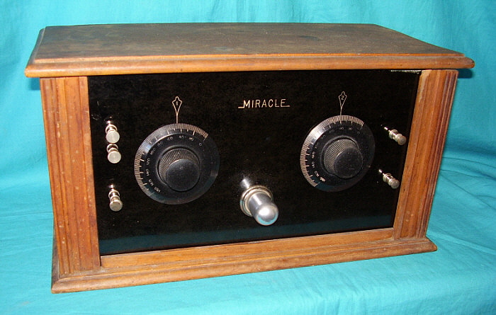
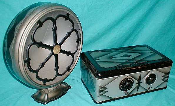
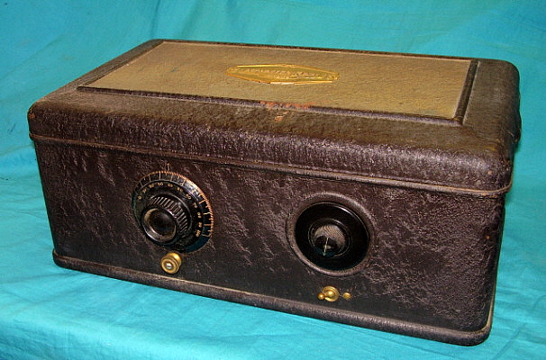
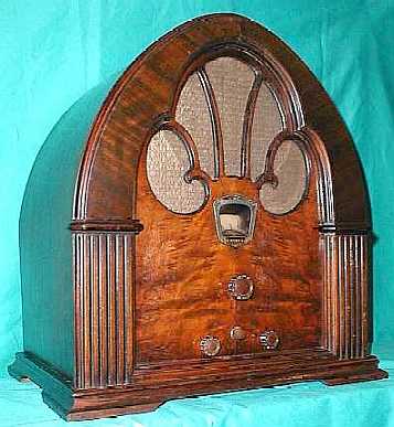
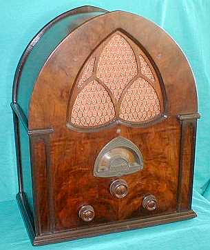
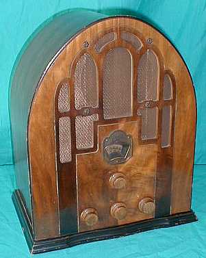
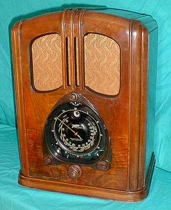
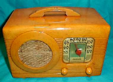
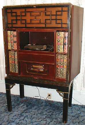
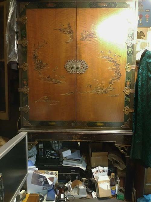
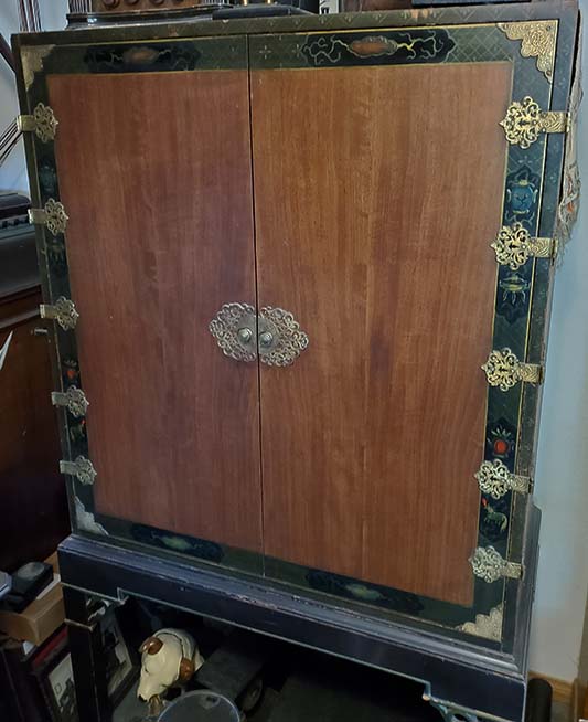
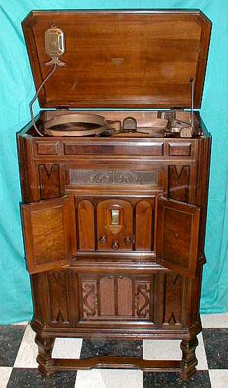
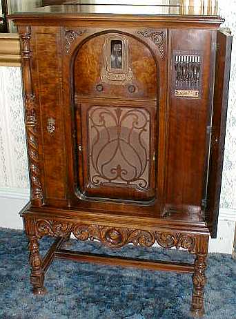
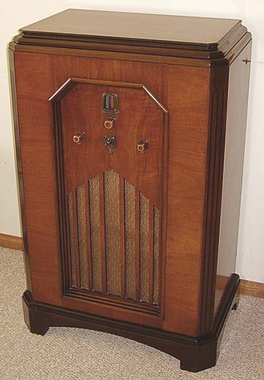
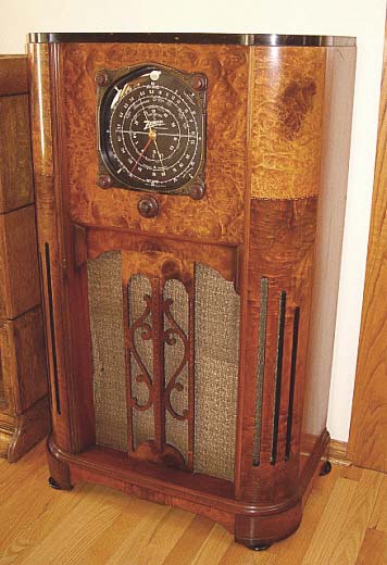
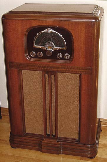
On an additional note: Some Synchrophases will be found with a greenish-gray color to the finish (as seen in the top photo.) This is a reaction that the original finish has with excessive exposure to sunlight (UV.) The original finish was medium walnut color (as seen in the lower photo.)

For the ultimate information source on the Grebe Synchrophase MU-1, including chronological listing of engineering-production upgrades, restoration hints and neutralizing the MU-1, go to "A Guide to the Synchrophase MU-1." Link below in Navigation Index.


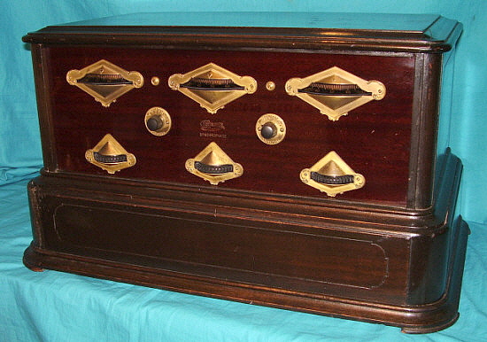
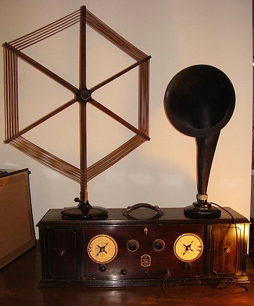
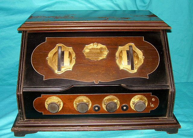
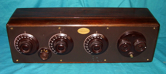
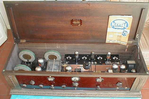
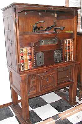
photo above:  Grebe MU-1 CTPB with optional Battery Box. This MU-1 does not have the chain drive and has the "VOLUME" and "FILAMENTS" controls - no "TONE COLOR" control.


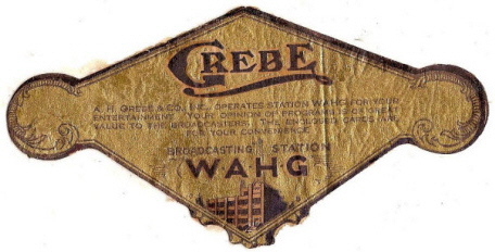
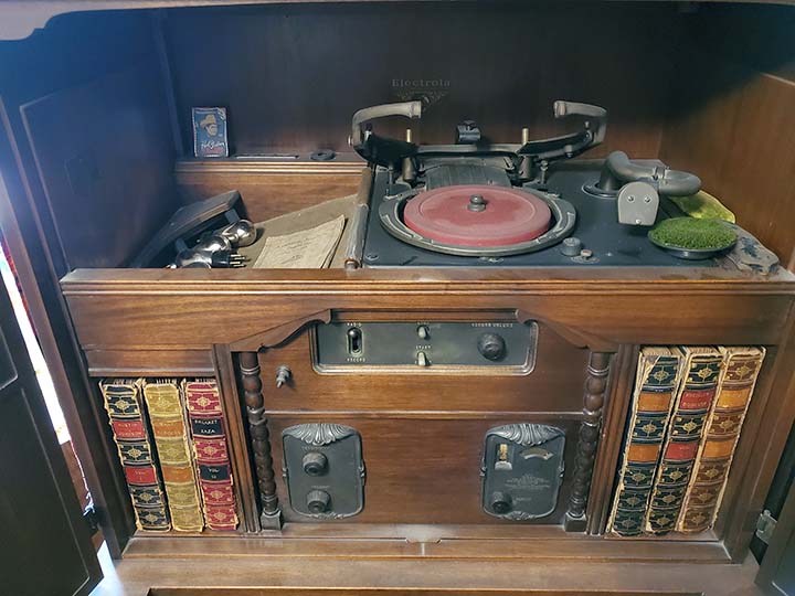
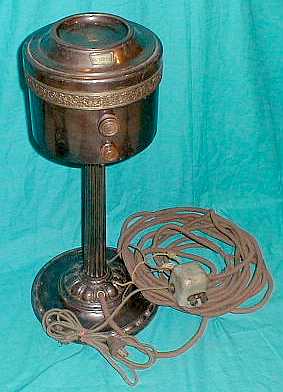
photo above: This advertising label was installed inside the cabinet wall on the right side. This label advertises Grebe's Broadcast Station WAHG and also mentions the packet of Grebe QSL cards that were supplied with each receiver.


Stine Electric Store - San Francisco

"REX-O-DYNE"
 

By late-1924, all radio fans had been hearing names like "superheterodyne," "neutrodyne," "thermiodyne," etc., mentioned in all of the radio magazines or in other advertising. The variations of names ending in "dyne" were almost endless. But, here's one more,...the "REX-O-DYNE," or, the "King of the Dynes." Not that there was ever much innovation in the circuits, most were standard TRF using what was more-or-less a public-domain type of circuit so that the radios really weren't of much interest to the lawyers from the IRM or the Radio Group. However, Stine Electric Store was located in San Francisco, California and that location was important for those who wanted to build radios and probably avoid any sort of patent litigation. The major patent holders weren't very concerned with any radio manufacturing going on west of the Mississippi, so California radio builders had pretty much free-reign to build whatever circuits they could get away with. Most of the western radio builders didn't have enough sales to warrant any patent infringement worries from the big eastern radio companies.

Stine Electric Store was probably a small shop that dealt in "all things electric" and certainly radios would have been part of their sales. The "REX-O-DYNE" is obviously built from easily obtained components. Even the cabinet was a purchased piece. In the 1920s, it was fairly popular for a small "radio" store with a talented owner to build a few radios to sell every so often. The engraved front panel might have been "farmed out" and the cabinet purchased but the radio itself looks like it was probably built at the Stine Electric Store. Workmanship is fairly crude, especially fitting of the radio chassis into the cabinet. The radio's exterior, however, is exquisite. 

The "REX-O-DYNE" circuit uses three tubes in a "double-reflex" circuit. Reflexing was first described in the 1923 LeFax Radio Handbook as a method of routing a RF signal through an amplifier tube and then routing the audio signal through the same tube. Since the frequency difference was substantial, there was little interaction between the two signals and the tube amplified both signals simultaneously. The "REX-O-DYNE" has one 201A tube functioning as both a First RF amplifier and a First AF amplifier while a second 201A tube functions as the second RF amplifier and second AF amplifier. The third 201A tube functions as the detector. Usually only one tube is reflexed in this type of circuit but it is possible to use two stages of reflex operation. This essentially has a three tube receiver actually functioning as a five tube set.   >>> 

>>>    The audio output is routed to a built-in horn speaker that looks like it was salvaged from an old Wurlitzer battery set. Another interesting circuit in the "REX-O-DYNE" allows it to operate on the AC line, although this is probably a somewhat later addition. The power supply is located in the left compartment and is contained within a cardboard box. It's a really nice cardboard box that has a black leatherette finish to it. Interestingly, a type UX-112A tube is used as the half-wave rectifier in this circuit (grid tied to plate.) The RF coils used are flat, "spider-web" type, low-loss coils. Thordarsen interstage transformers are used. Most reflex radio circuits date from around 1924 but some of the components in this REX-O-DYNE seem a bit later although these later components might be from updates added later in the radio's life.


GE and Westinghouse for RCA

Radiola 20


Why RCA offered the Radiola 20 is a mystery. RCA was practically the only company that could legally sell superheterodynes and here they were offering a TRF front-end with a Regenerative Detector followed by two stages of audio amplification. Certainly by 1925, the Regenerative receivers had fallen out of favor with AM Broadcast listeners who didn't like the interference caused by their neighbor's regen-set when it was oscillating. However, some realized that the regen-detector was about the most sensitive detector of the day. RCA added two stages of RF amplification in front of the regen-detector that isolated it from the antenna, eliminating the possibility of interfering with your neighbor's radio.

The Radiola 20 tuning condenser is ganged together to provide single-dial tuning but two trimmer condensers allow for fine tuning for best accuracy. Regeneration is labeled as "Amplification." The two pin jacks on the right side of the panel are for an external filament voltage meter. Using four UX-199 tubes and one UX-120 tube, the Radiola 20 is a surprisingly good performer. The UX-120 is run at +135vdc with a -22.5vdc bias and the RF stages are also biased with -4.5vdc. Several different B+ voltages are required for the circuit to perform as designed. When operated correctly and with a good quality cone speaker, the Radiola 20 sounds good and is very sensitive. Note that the escutcheons on this Radiola 20 are the early versions that were given a "gold wash" - sort of a very thin gold plating. Later versions of the Radiola 20 have bronze-patina finish escutcheons that are much darker and certainly are the most often seen type of escutcheons on the Radiola 20.


Atwater-Kent

Model 20 "Big Box"  &  Model 20-C  "Compact"

Atwater-Kent liked the appearance of his components and his breadboard sets reflect his opinion. However, consumers in the mid-1920s - at least those that weren't "technoids" - wanted enclosed radios that didn't show any of the tubes and wires that radio enthusiasts enjoyed looking at. Additionally, there were the "electro-phobics" that were always afraid of anything running on electricity and to them the exposed terminals of the breadboards caused no end of concern.

A-K finally enclosed the breadboard design in a mahogany cabinet with a metal front panel that was painted brown crystaline enamel (A-K's name for "wrinkle finish") and the set was designated the Model 20.

Today's collectors have dubbed this first version the "Big Box" in contrast to the later Model 20-C or Compact. The 20-C reduced the size of the cabinet to the absolute minimum as there's very little space inside the cabinet that isn't radio components. A battery cable is brought out the rear of the 20-C cabinet to allow the set to be connected to batteries. Terminals inside provide connections for the horn speaker and the antenna-ground system. The 20-C was popular and A-K sold a lot of them. High quality components and good performance as was typical of Atwater-Kent.

The early version Model 20, aka, "Big Box"

The later version Model 20, aka "Compact"


The AK-20C was gotten in a trade with Paula Hardy of Virginia City. Paula had been a radio collector, well,...a collector of everything really, for many years and had the "Museum of Memories" in Virginia City. She also owned the Odeon Hotel in Dayton and it was filled with radios too. This was in the mid-1970s. When Paula died, her son sold all of the contents of the museum and eventually sold the building too. I have another AK-20 from Virginia City that was found in a garage in town by the guys that painted our house. That was in the 1990s. Another AK-20 showed up from a basement collection in Carson City a few years ago,...like I said,...AK made a lot of AK-20Cs and they were really popular radios.


F.A.D. Andrea, Inc.

FADA 6   Model 460-A
 

The smallest and the least expensive of the Lewis Clement-designed Neutrodyne receivers, the FADA 6  was a popular model and probably the model that most collectors have encountered. At $150, the FADA 6 was still quite a bit higher priced than the average radio in 1926 but what appealed to prospective buyers was the fact that the radio could actually receive stations quite well with just the built-in loop antenna. That eliminated the task of erecting some type of outdoor antenna with the expense of masts, wire and lightning arresters. The FADA 6, of course, uses six tubes. An antenna tuner amplifier stage, two stages of TRF, one detector and two stages of audio amplification with all tubes being UX-201A types except the last audio stage which could be either a UX-112-A or the UX-171-A.

The two tuning dials are placed together on the FADA 6. The right control adjusts wavelength and the left control adjusts the loop tuning. If an outdoor antenna is used and it's a very long antenna, then the antenna tuning control will have little effect. The loop provides good signals and directivity.

The lower control is coaxial with the outer knob controlling the filament voltage and audio volume. The inner control is a gain selector with three steps provided, LOUD, MEDIUM and SOFT. This control selects how many audio stages are used with LOUD using all stages, MEDIUM using one stage and SOFT using just the detector output.

There is another gain control located under the lid. If an external antenna is used then the loop antenna terminals must be pulled out of their sockets. Folding down the loop also shorts the loop to prevent spurious stray coupling.

Although the tuner, detector and audio circuits are in shielded boxes, no tube shields were included with the FADA 6. Shown in the brochure to the right are both the FADA 6 and the FADA 8. The artwork at the top shows the FADA 8 chassis.


F.A.D. Andrea, Inc.

FADA 8   Model 480-A
 

The "Actual" Best Performing Battery-era Neutrodyne Radio


photo above: The FADA 8 shown in the photo is fully functional. It did require rebuilding of the meter switch, rebuilding one shorted bypass capacitor and some minor repair to the loop. I power the FADA 8 using a RCA Duo-rectron for B+ requirements, a small adjustable dual power supply for the two -C requirements and a 6V 4A Lambda power supply for the A supply. Performance is incredible and the very powerful audio doesn't even sound like a battery-era radio. The large Western Electric 540AW 18" cone speaker is dwarfed by the immense size of the FADA 8. FADA did sell a very large cone speaker to go with the FADA 8. It was available as a table top speaker or it could be purchased with a floor stand. These speakers weren't cheap either, $35 for the table top and $50 for the floor model.

Frank A. D'Andrea was the first Neutrodyne licensee of the Independent Radio Manufacturers. D'Andrea's company, who had been making crystal detectors, became the first to offer a Neutrodyne receiver to the public in late-1923. D'Andrea had actually shortened his name to Andrea some time earlier and had several jobs before going into radio. During WWI, he was associated with DeForest and by 1920 had his own company producing crystal detectors. A law suit over crystal detectors caused Andrea to broadened out to complete radios and kits after becoming a member of the eleven Independent Radio Manufacturers. Around late-1925, Andrea hired engineer Lewis Clement who designed a series "ultra high-end" Neutrodyne receivers. The same basic "cost-no-object" design principles were incorporated into six, seven and eight tube chassis that were then installed into table or floor model of cabinetry. These "over-built" radios were expensive and provided "top-of-the-line" performance. The radios were complicated to "hook-up" employing battery cables that had at least ten different battery connections. In the late-twenties, F.A.D. Andrea, Inc. was purchased by  investors and went bankrupt in the early thirties. Frank Andrea had already started Andrea Radio Corp. by that time and that company continued on and was in business for decades.

Selling price was $300 in 1926 and that didn't include the eight tubes needed and the price was even higher West of the Rockies (the console version, Model SF 50/80, was $400 - approaching the cost of a new automobile.) The FADA 8  Model 480 "table model," was the largest of the Lewis Clement-designed, massive, Neutrodyne receivers. At 32" wide, 15" deep and 14" tall along with topping the scales at 80 pounds, the FADA 8 is a behemoth. Everything a radio fan could want and could afford was installed, including a built-in, fold-out loop antenna, a front panel meter that measured the filament voltage and could also, by rotating the "Meter Switch," measure any of the four B+ voltages. Additionally, the number of audio stages used could be selected from the front panel. The new UX-171A audio output tube could operate with up to +180vdc on its plate providing thunderous volume. The audio output +180vdc B+ is coupled to the UX-171A plate thru a choke and the audio output is coupled to the loud speaker using a 1.0uf capacitor. This eliminates the B+ from appearing on the loud speaker terminals. With an excellent condition and well-designed cone speaker, the audio is powerful and impressive, not sounding like any other battery-operated radio. Sensitivity and selectivity are undoubtedly the best that could be achieved with battery operation and a Neutrodyne circuit. The Lewis Clement-designed FADA 6, 7 & 8 will give any of its contemporary superhets some real competition. These FADAs can certainly out-perform the Grebe Synchrophase receivers, although the Synchrophase MU-1 was a five-tube set and just about to end production at the time the FADA 6, 7 & 8 were introduced.

The FADA 8 uses one stage of tunable antenna amplification, three stages of Neutrodyne TRF amplifiers and one Detector stage. Each RF stage is fully shielded as is the detector stage. A two-piece metal box comprises the shield for each stage. All three AF amplifiers are within one shielded box. Each tube has its own shield cap that fits to the top of each shield box and completely shields each stage. Heavy cast "howl supressors" were available for the audio tubes and the detector tube to prevent microphonic feedback. Each stage is fully bypassed with fixed-value capacitors.

The two tuners adjust the Antenna (left control) and the Wavelength (right control.) The loop performance is incredible for such a small antenna but there is so much gain available there is no disadvantage to using the built-in loop when it is deployed in the upright position. With an full-size outdoor antenna, the Antenna control will usually have little effect due to the high inductance but DX reception is generally improved over the loop.

While certainly some 1926 owners ran their FADA 8 receivers on batteries, the manual suggests that a FADA-Philco ABC Battery Eliminator should be used. In 1927, the FADA 8 was redesigned to eliminate the panel meter and simplify the front panel controls. When introduced, it was called the FADA 8  Model 480-B. The earlier Model 480 had been often referred to as the Model 480-A even before the Model B introduction.


E. M. Sargent

Infra+Dyne

Building a superheterodyne in the late-twenties was a risky-business. If the radio's performance was great and the sales substantial then it was very possible that Westinghouse, GE, RCA and the Radio Group lawyers would threaten a lawsuit to stop production. Sometimes a location on the West Coast would provide distance and isolation from the Radio Group's interest but a good radio with a lot of public interest was sure to foment a reaction from the Radio Group's lawyers. One way around all of the superhet problems was to offer the radio as a kit. Since construction of a superhet kit limited interest to radio enthusiasts with a talent for construction, sales were never going to attract the attention the superheterodyne patent-sales protection lawyers of the Radio Group. Another protection plan was to obfuscate exactly what the radio circuit accomplished, thus confusing the patent-busting lawyers. E. M. Sargent took both approaches with his Infra+Dyne receiver.

E. M. Sargent was a small radio builder located in Oakland, California. In 1926, he produced a radio kit that was promoted as "a new circuit" with "quiet background noise and great sensitivity." The radio circuit was called the Infra+Dyne, a name certain to confuse any non-technoid lawyer. Sargent also published a few booklets on the Infra+Dyne that explained all of the radio's design ideas without ever mentioning the word "superheterodyne" in any of the text. However, the Infra+Dyne is an up-converting superhet. The famous Remler Infradyne Amplifier is basically a three tube IF amplifier. That it operates at 3500kc is something unusual - the normal superhet of the day probably used around 180kc IF (since those all down-converted.) The fact that the IF is a product of up-converting, the LO has to tune "backwards" in order to keep both dials seemingly having similar readouts. Ten tubes are used in the Infra+Dyne circuit. A mixture of both UX-199 tubes and UX-201A tubes are utilized. Two RF amps, Mixer, LO, three IF amps, detector and two AF amps comprise the tube lineup. The coils in the front end were originally specified as Thorola Toroid "Donut" coils but later Silver-Marshall coils were recommended. Remler was usually the source of the tuning and LO condensers. Jewell supplied the filament voltage meter, National Co. supplied the vernier tuning dials on many examples and Thordarson was usually the audio interstage transformers of choice. Since the kit was essentially the plans, schematics, blueprints, booklet and some of the unique parts, like the IF section - the Infra+Dyne Amplifier, or the front panel and several other parts specific to the design. Many of the other parts or custom changes had to be purchased. These purchased parts account for the variability of construction in all of the examples of Infra+Dyne radios.

When operational, the Infra+Dyne does work quite well. The 3500kc IF does result in a very quiet background noise and the addition of the two RF amplifiers results in adequate sensitivity - at least for the AM BC band. Several different voltages are required to power up the Infra+Dyne. Unfortunately, the actual receivers are quite large. With ten tubes and an IF strip that's sixteen inches long, most Infra+dynes end up being very long radios.

I've owned two Infra+Dynes. The first was a professionally built one labeled as a "Remloc" and it's shown in the photo to the left. It was built in San Francisco. Clearly, it violated the superhet patent since it was sold as a complete, ready to operate radio. However, being in California did provide most small radio-building operations some protection due to the distance between them and the Radio Group lawyers in New York City. The Remloc did function and, after a bit of adjustment to the IF strip, it provided decent performance. It had been built using Thorola "Donut" Toroid Coils. It had a fabulous cabinet and a red mahogany bakelite front panel. The dial scales were illuminated on the Pilot vernier dials. Unfortunately, I sold the Remloc several years ago.

My currently owned Infra+Dyne is shown in the top photo and it was positively built as a kit. Construction is fairly good but certain areas show the amateur-quality found in most kits. This Infra+Dyne is built with Camfield Duo-Coils (binocular types that perform similarly to toroids.) Whether there ever was a cabinet for this Infra+Dyne is unknown. I found as it is, sans cabinet.


Custom-Built Glass Case Neutrodyne Radio

Built by: E. H. Browning, June 20, 1927, Portland, Oregon

Radios that were built into cabinets made of glass served two purposes. First, for the radio parts dealer, it displayed what type of components were available and how they would look in a home-made radio. It's also possible that some dealers actually would build custom radios and the glass cabinet again showed the typical construction and layout of components. There were also instances where a special glass case was used for display of a radio company's model (used by dealers) that would show potential customers the internal construction of the particular model (this use was fairly uncommon.) The second use was a talented "homebrewer" that just wanted to show his building prowess with a radio that was uniquely different. Certainly Glass Case Radios are seldom encountered. They are rare because there were so many problems involved in using glass as a medium for the construction that few were ever built. Today, Glass Case Radio survival depends on the durability of the cabinet to withstand the effects of time, poor storage, careless moving and neglect. Also, the chassis must have been able to survive similar conditions. Most Glass Case Radios date from the mid-to-late twenties. They shouldn't be confused with the glass-mirrored radios of the thirties that were produced by true radio factories (Sparton and some others.) The Glass Cased Radios were built specifically to "show off" the construction and components of the radio circuit, either for dealers or for enthusiastic homebrewers.

The Glass Case Neutrodyne Radio shown above dates from 1927. It was built using primarily components made by the Bremer-Tully Company (B-T.) Six tubes are used in the Neutrodyne circuit, three RF amplifiers, a Detector and two stages of transformer coupled audio amplification. The RF coils use chokes that isolate them from B+ (chokes are made by B-T.) The neutrodyne feedback capacitors are also B-T as are the B-T "TOROSTYLE" (toroid) RF coils.* The dual-section tuning condensers each have an additional trimmer condenser. The tuning dials are National Type B Velvet Verniers. The audio interstage transformers are 4:1 ratio on the 1st AF and 2:1 ratio on the 2nd AF and both are B-T Type T-210 "EUPHONIC" transformers. All of the tube sockets are Type 349 General Radio sockets except for the cushioned detector tube socket which is made by the Benjamin Company. Audio output is accessed via the front phone jacks and the operator can select either one or two stages of AF amplification. Power is supplied by batteries and these are connected via binding posts on the rear of the chassis with the exception of the C bias battery which is connected with flexible wires.  >>>

>>>  The radio is physically rather large at 32" wide and 13" deep. The chassis is made of bakelite. The glass pieces are held in brass channels that are screwed together or soldered to form the glass cabinet. The base is redwood. Fortunately, this Glass Case Neutrodyne Radio was signed and dated by the builder (which is somewhat unusual.) On the bottom of the wooden base written in pencil is "Bilt (sic) by E.H.Browning, June 20, 1927, Portland, Oregon."

*The toroid style coil form will not radiate an EM field and therefore will not couple to an adjacent RF stage via stray coupling. This leaves only tube interelectrode capacitance coupling that is "balanced out" using the Neutrodyne feedback condensers. The neutrodyne provided high gain and high selectivity without RF stage oscillation.


Crystal Sets


Uncle Al's Radio Shop

"Miracle" Crystal Sets

Uncle Al's Radio Shop built the best performing and certainly the most selective crystal sets available in the 1920s and early 1930s. The crystal sets were sold mainly in the West and most often in California's San Francisco Bay Area. Uncle Al was actually Alex Forbes, who, along with his brother, Henry, built and sold uniquely designed crystal-detector receivers during the 1920s and 1930s out of Oakland, California. Uncle Al's Radio Shop probably started out at either Alex's or Henry's residence in the 1920s. Most of the early crystal sets will have an address on the paper tag under the lid with one of two locations shown, either on Dakota St. or 27th Ave in Oakland. Later locations are at 3905 Hopkins St. in Oakland. Whether Alex Forbes had an actual radio shop (doing repairs and sales) in the early twenties is unknown. By the early 1930s, he was doing business out of a shop location on Hopkins St. that did advertise service and sales.

The Miracle Crystal Set uses multiple coils with fairly loose coupling with variable condensers for sharp tuning. The resulting selectivity is a "Miracle" with Uncle Al's crystal sets having tuning that acted like the popular TRF battery sets of the mid-twenties. Most crystal sets of the time used either "self-resonant" coils that shorted turns for tuning (like Philmore) while others merely had an LC on the antenna with a diode detector, capacitor and phones (some homebrews.) Both of these types of crystal sets will receive multiple stations simultaneously due to their lack of selectivity. Uncle Al's circuit used loose coupling combined with bucking coils for selectivity along with tuned input and tuned detector pick-up coil for better sensitivity. Uncle Al's tuning circuit made the "Crystal Set" a radio receiver that could separate several broadcast stations received within a local area. By 1925, when Uncle Al was introducing his No.1 type, the AM BC band was unofficially 550kc up to 1500kc and within an area like the San Francisco Bay Area several broadcast stations were operating by that time. The Uncle Al's Crystal Set would be able to separately tune each of those stations - something a Philmore or Lemco couldn't do.

The "Miracle" shown in the photo is a No.1 version probably from the mid-1920s. It has two antenna binding posts, the upper is for shorter wavelengths and the lower is for longer wavelengths. The tag under the lid has an address of 27th Ave. which is later than the first sets from Dakota St. but it is still the No.1 type. Uncle Al's cabinets are not finished or they might have been coated with a thin shellac finish that normally is not present on examples found today. Supposedly the wood used for the cabinets is eucalyptus which is very common in that area of California. Uncle Al was always improving the "Miracle" so it wasn't long before the No.1 was replaced with the No.2 with its rotating spider-web detector coil with an adjustment knob between the two tuning knobs. The crystal-detector used on both the No.1 and No.2  was similar to those made by Grewohl although they are from a different source.

Uncle Al's Radio Shop is still in business in Oakland, California, (though they now sell and service TVs.)

Thanks to Dan Merz for all of the Uncle Al's Radio Shop history.

The photo right shows a late-1930s Uncle Al's Radio Shop promotional card. Note that the card states "MANUFACTURER OF OVER 10,000 SETS - SATISFACTION GUARANTEED!" 


Beaver Laboratories

"Baby Grand"

Certainly one of the smallest radios built in the twenties, the Beaver Laboratories' Baby Grand is shown next to a quarter for size reference. This tiny crystal set dates from about 1922, or so. It is not certain if the Baby Grand was originally considered a "novelty" or a "real" crystal receiver.


Betta-tone Radio Co.

"Betta-tone"

These small crystal sets, built into a file-boxes, were popular in the mid-twenties. Construction was usually good and performance was satisfactory considering the low price they sold for. The Betta-tone is from about 1924. Like most of its contemporaries, the Betta-tone features a tapped coil with switched contact controls for tuning in stations and a "cat's whisker" to find a sensitive spot on the galena crystal for detecting the incoming signal. Earphones connect to the right binding posts while the aerial and ground connect the left binding posts.

There was also another crystal set that is almost identical to the Betta-tone, built by Lemco, aka Lee Electric & Manufacturing Company in San Francisco.


Early AC Radios (1927-1929)


Atwater-Kent

Model 37 - "Modernistic Style"

The Model 37 was Atwater-Kent's first, self-contained, AC operated radio (the Model 36 had a separate, AC power pack.)  Rugged construction and the TRF circuitry resulted in a reliable, good performing radio. Although nearly all of the Model 37 production was finished in a brown wrinkle finish called "Crystaline Enamel", sometime in the production year of 1928, a small number of Model 37 radios were finished in an "art deco" style. These Model 37s were dubbed "Modernistic Style" and featured a matching Type-E speaker. The silver and black decor was achieved by using stencils and a light spray painting technique - something like "air brushing."  The finish was very thin and thus was subject to much wear. It's very common to find "Modernistic Style" cabinets with a lot of chips and scratches. Originally, the paint on the "Modernistic Style" was not a glossy finish but was more of a "matte finish" or "semi-gloss." There are two variations of the Type-E speaker. When the "Modernistic Style" matching speaker was fitted with the "thin wood" type of cone, the cone was painted flat black. When the "Modernistic Style" matching speaker was fitted with the thick embossed paper cone, the cone was painted silver. The Type-E speaker shown above has the paper cone and is all original with its proper silver paint. Estimated production is around 10,000 radios, which for Atwater-Kent was a "small run." Today, the "Modernistic Style" is rarely seen. Fortunately, most examples that turn up seem to have the matching Type-E speaker still with the radio - probably because it's pretty obvious that the two pieces went together. This particular "Modernistic Style" was originally purchased in San Francisco and for years made its home in San Francisco's "Chinatown."


Atwater-Kent

Model 40

The Model 40 was one of the most popular of the metal boxed, AC-operated radios produced A-K. Probably, the reason that so many have survived is that the radio was built like a little "tank." There might be problems that develop in the power supply which is filled with hard wax. This makes repair of the power supply somewhat difficult. However, many Model 40 still operate fine on all-original parts. A-K made all of their own components and most of them were high-quality parts. The 1928 A-K Model 40's circuit is TRF and uses seven tubes.

The Model 36 was the first AC-operated radio from A-K in 1927 and the Model 37 was the first AC-operated metal box radio with built-in power supply (and the Model 35, a six-tube battery set from 1926, was the first A-K metal box radio.) Arthur Atwater-Kent felt that the mahogany wooden cabinets he had been making cost too much to manufacture. He knew that a stamped steel cabinet would be cheap to make. It could be painted which was also cheap and easy to do. He just had to convince would-be radio purchasers that these painted steel boxes were stylish and would fit in with the late-twenties decor. With a lot of advertising, A-K was able to change the tastes of radio buyers and the metal box radios became quite popular for a short time, about 1928 up to 1930. A-K even sold a console radio in a metal cabinet. Today's tastes are very different and many collectors find all of the metal box radios ugly, regardless of who the manufacturer was.

The A-K Model 40 shown belonged to M. H. Dodd and was acquired along with Dodd's 1912 Wireless Station in 1999. This Model 40 has the earlier style tuning dial. Later versions have larger numbers and a different style grip. While the Model 37 top tag depicted the Mayflower (or, at least a sailing ship,) the Model 40's tag just has "ATWATER-KENT" embossed on it.


Atwater-Kent

  Screen-Grid Model 55

One of the last of the stamped metal box TRF radios from Atwater-Kent, the Screen-Grid Model 55 uses type 24-A tubes. These are tetrodes which have more gain than the type 26 triode tubes used in earlier models. The Model 55 also uses an electro-dynamic speaker, housed in a round metal cabinet that is mounted to a small pedestal. The design of these speakers are very close to the speakers used in all later radios consisting of a field coil magnet and a low-Z voice coil with paper cone. Some of the construction is slightly different in that a separate suspension is used around the rim but basically the A-K speaker is modern in design. Sound quality (for a 1929 table radio) is very good.

The Model 55 was a departure for A-K in the paint finish. Unlike the earlier metal boxes, the Model 55 is painted with high-gloss lacquer. This particular one is in black and green, however sometimes black and red was used. Since the finish was smooth and glossy, it's very unusual to find any Model 55 that's in good condition, cosmetically anyway. Most examples are severely chipped because the smooth lacquer didn't have the durability of the heavier wrinkle finishes. The Model 55 shown is the best condition one I've encountered. There are a few chips where the speaker sat on top of the set but otherwise it's in excellent condition. Nice cosmetics really doesn't help since most collectors still find these metal box radios hideous looking.


RCA

Radiola 60

RCA's "tour de force" superheterodyne, the Radiola 60, was certainly the best performing superhet available in 1928. AC operation, 9 tubes, powerful sounding audio from a single-ended 71-A, cathode type 27 tubes used in the rest of the radio with the exception of the type 80 used for the rectifier. The Radiola 60 was well-built and today many still function quite well on all original parts. The weakest point of the radio is the multi-tap wire-wound resistor used to reduce voltages for various functions. Since this puts the B+ in a series string, if any section of the resistor opens, then the radio will not function. It's easy to repair by installing a correct value WW resistor across the open section. The Radiola 60 IF operates at 180kc. With an outdoor antenna, the Radiola 60 will pick-up just about any signal on the AM BC band. Unfortunately, RCA didn't include a calibrated dial, the Radiola 60 uses a 0-100 scale on the tuning. Two types of escutcheons are found on Radiola 60s - dark bronze, as shown in photo and also, black with silver lettering.

There were a few different speakers available for the Radiola 60. The Radiola 100A was a metal "mantle clock shaped" that sounded quite nice. The speaker shown in the photo left is the Radiola 103 "Tapestry" Speaker. The frame of the speaker is made out of "repwood" or sirocco, a pressed wood that could be molded into any shape. This was then stained. The speaker mounts to the back of the frame and then a cardboard cone was mounted behind the speaker. The cardboard cone was covered with very fine brown cloth. For not having a true cabinet, the Radiola 103 sounds surprisingly good.

The first vintage radio that I bought for myself was a Radiola 60. I was fourteen and paid seven dollars for it (in 1964.) It was a consolette Radiola 60 sold by Sherman-Clay in 1932. Sherman-Clay had bought "left over" production Radiola 60s (very cheap in 1932.) They then had a local California cabinet shop build the console base and install a Jensen Concert Dynamic Speaker. These radios were then sold as "new" models in 1932. The Jensen speaker does make the Radiola 60 sound like a 1930s console. And,...yes,...I still have this Radiola 60 consolette some 55+ years later.


Classic Thirties Radios (1930 to 1938)

Philco

Model 90

Is the Philco 90 the quintessential vintage radio? Certainly it is what most non-collectors visualize as an "antique" radio. Introduced in 1931, the nine-tube superheterodyne chassis was considered a console radio in a table cabinet by many advertisers. The first models had Push-Pull 45s for audio outputs. Later, AVC was added and a single 47 supplied the output. Most cabinets will have the month and date of manufacture stamped on the bottom. Original selling price was $69.50. The sound quality is excellent and the styling timeless.

 
ak84.jpg (17860 bytes)

Atwater-Kent

Model 84

The Atwater-Kent Model 84 featured a "classic" cathedral styled cabinet with booked, figured walnut veneer front and linear walnut veneer sides. The six-tube superheterodyne receiver was built on a nickel-plated chassis. The speaker was an eight-inch electrodynamic giving the AK 84 excellent sound quality. It was a popular model with two AC versions available, (60Hz "Standard - no letter" and 25Hz  "F" type) and two DC versions available, (110vdc "D" type and battery "Q" type), plus variations between early and late models in all versions. The AK 84 originally sold for $69.95 in 1931. The AK-84 is another "timeless" style cabinet design.


Atwater-Kent

Model 165

Atwater-Kent offered this five tube receiver in 1933 for the low price of $29.90. Featuring a very delicate fretwork on the grille, a nickel-plated chassis and a large eight-inch speaker, the 165 provided the user excellent sound with a beautiful gothic-styled cabinet.  Police calls could be received by switching the combination Tone-Police control to Police. The switch shorted a few turns on the coils to shift the frequency somewhat higher. No calibration was provided on the Police frequencies. The circuit uses a 57 converter, a 58 IF amp, a 2A6 Det/AVC/1st AF Amp, a 2A5 Audio Output and an 80 rectifier.


Atwater-Kent

Model 206


Atwater-Kent's mid-priced table model radio for 1934 was the Model 206. The chassis used six tubes, which included an RF amplifier, converter, IF amplifier, duplex-diode triode for Detector, AVC and 1st AF amplifier functions, a pentode audio output stage and the rectifier. The speaker, like many A-K table models was rather large at eight inches diameter and provided a nice quality to the sound produced. Three tuning ranges provided are for AM-BC, Police and Short Wave. Also, a three position tone control was included. The cabinet was a combination of gadrooned pilasters, Japan trimmed base and walnut veneers. The control that is just below-right of the dial is a dual function with coaxial shafts and dual knobs used for the two-speed tuning. The other similar-shaped knob that is below-left of the dial appears to be for a dual function control but is actually only a single function control. Priced at $49 in 1934.

As an interesting note, this AK 206 is the last radio that was donated to the Western Historic Radio Museum while in Virginia City, Nevada. I had already closed WHRM to the public and was in the process of moving everything to Dayton, Nevada. There would be days go by when we weren't even in VC but were down in Dayton. After an absence of probably a week or so, we went back up to VC to move another load. Upon arrival, I went up the back stairs to go into the house and there setting on the back porch was this AK-206. No note was found with the radio so I have no idea who placed it on the back porch. But, practically everyone in VC knew about the WHRM so this wasn't the first radio donation,...it just happened to be the last radio donated to "WHRM."


Zenith Radio Corp.

Model 805

By 1935, Zenith was considering the "cathedral" style of cabinet a bit archaic. The 805 was the last cathedral Zenith offered even though a few other manufacturers continued with the style for a year or two more. This little five tube set is a good performer and the two tone finish with black Japan trim is quite attractive. Covers BC and one Shortwave band.

This Model 805 is in excellent all original condition. It didn't come out of Reno though. This little radio was found by NU6AM in an antique shop in the San Francisco Bay Area of California. 


Remler Model 43

Remler Co., Ltd.
Gray & Danielson Mfg. Co.

Model 43

Remler was in business, in San Francisco, an incredible 70 years. Founded in 1918, by Elmer Cunningham, Thomas Gray and Ernest Danielson. By 1922, Cunningham had gone off to RCA and Remler was then solely owned by Gray and Danielson. Remler specialized initially in parts, components and small assemblies but went on to market the first up-converting superheterodyne kit receiver, E. M. Sargent's Infra+Dyne. Another Remler employee, Gerald Best, was responsible for the "Best" Superheterodyne kits. Both of these kits were available in the late-twenties. In 1928, Gilfillan Bros., Inc. in Los Angeles became the exclusive license holder for many RCA circuits, specifically the TRF at that time. By 1931, the superheterodyne was added to Gilfillan's exclusive licenses. Essentially, all legally manufactured radios built in the eleven Western states had to go through Gilfillan in some manner. A 5% licensing fee was charged for each set and that was divided between Gilfillan and RCA. But what about Remler? How were they able to build radios in San Francisco apparently without Gilfillan being involved? Two possibilities - Remler's output was so small that they didn't interest Gilfillan or RCA. The other possibility is the Elmer Cunningham connection that may have resulted in a RCA license agreement that pre-dated the Gilfillan deal. At any rate, Remler was able to build radios in San Francisco without any Gilfillan involvement.

During the thirties, Remler built a variety of small items for other companies, like tube plate caps for Eimac and other special machining products. With WWII beginning, Remler started to produce communication equipment for the military. After the war, Remler was back at building consumer radios, still producing the Scottie radios they had introduced in the late thirties. Remler continued to produce various types of electronic and specialty machined products into the 1980s. The 1988 death of Robert Gray Jr. (grandson of the original Gray) quickly followed by the death of company VP Paul Karp left the company with no leadership. The company doors were closed shortly after that and it was the end for Remler.

The Model 43 is a seven tube superhet built around 1937. It uses all metal octal tubes, has a single RF preselection stage, one IF amplifier operating at 450kc, a single-ended 6F6 AF output tube and a large 8" speaker that has the tuning dial mounted in front of it. The chassis is painted green wrinkle finish - cool.


Zenith Radio Corp.

Model  5-S-127


Small tube-count, table model radios were good sellers and the five tube circuit was just about the minimum number of tubes for a superheterodyne circuit to function with. The rectifier tube reduces the number of tubes in the actual receiver circuit to four. The converter tube allows both local oscillator and mixer functions within one tube envelope. The IF amplifier tube accounts for one tube while the functions of detector, AVC and first AF amplifier are performed by a duplex diode-triode tube. Finally, the audio output tube accounts for the fourth tube. This use of multi-function tubes, the converter tube and the duplex diode-triode, allowed Zenith (and most other manufacturers) the ability to offer decent performance with a minimum number of actual tubes present on the chassis. The reduced number of tubes allowed for a lower selling price which appealed to many cash-challenged radio buyers in the mid-thirties. Price was $39.95.

Zenith provided the "Big Black Dial" even in these small tube-count radios giving the owner the impression of a substantial apparatus. And, for the average user, the performance was more than adequate. These five tube circuits do sound great on the AM BC band and the six-inch electrodynamic speaker responds well enough in the larger cabinet of these particular style radios. On shortwave however, the limited front-end selectivity allows rampant images to start showing up by 10mc. But, in 1937, only the shortwave enthusiasts would have noticed the images and most dedicated SWLs would have been looking for a larger tube-count radio for their shortwave listening.


Zenith Radio Corp.

Model 6-S-222

The "Cube" style, (introduced in 1937 with the 5-S-126), was so popular that Zenith kept it in the 1938 line-up at the same 1937 price of $39.95. The tube count was increased to six, although Zenith did this by replacing the duplex diode-triode (6Q7) with separate first audio amp (6F5) and a dual diode (6H6) so performance is about the same as the 1937 version. The larger cube radios featured AM BC plus two shortwave bands and a 6"speaker mounted in the top of the cabinet which resulted in a pleasing sound quality due to hearing the sound wave indirectly. In referring to the various "Cube" models one should use the proper model number since using just "Zenith Cube" is confusing because there are so many Zenith models that used various types of cube-style cabinets.

In 1964, for my fourteenth birthday, I was given a Zenith 6-S-222 for listening to shortwave. This was my very first radio and it started my life-long interest in vintage radios. Unfortunately, the 6-S-222 shown in the photo is not my original radio. In 1973, during a move, I made a hasty decision and my original 6-S-222 went to the dump. The 6-S-222 shown is the third one I've owned - I think I'll keep this one - even though I've never restored it to working condition.

6s222.jpg (15766 bytes)

 
7s232.jpg (24743 bytes)

Zenith Radio Corp.

"232 Series"

Models 7-S-232, 7-J-232, 9-S-232 & 12-S-232

For 1938, Zenith offered a deluxe table model radio featuring the new Robot Dial and Cathode-ray Tuning Indicator in a superbly styled, machine age cabinet. Four versions were available - two different seven-tube chassis, a nine-tube chassis and a twelve-tube chassis. The nine and twelve-tube models had motor-drive tuning.   All models utilized an eight-inch electrodynamic speaker, (except the "J" model farm-set  which used an 8" PM speaker.) These were expensive sets with the 7S232 selling for $74.95, the 7J232 going for $79.95, the 9S232 price was $89.95 and the 12S232 topping the price list at $99.95. Shown in the photo is the seven-tube AC model, the 7-S-232. It was found in Reno.

The 1970s TV series, "The Waltons," featured a 232 model in several episodes, hence the common collector nickname - Zenith Walton. It's confusing to use this moniker because it seems dealers have applied "Walton" to any of the 232 models. It's commonly believed that the Zenith used on the TV series was a 12-S-232, which should then be the correct "Walton" version. It's better and more accurate to refer to the particular radio by its proper Zenith model number - no confusion that way.

It's worth noting that the grille cloth on this 7-S-232 is a reproduction. When found, this radio had brown velvet for the grille cloth - cool. Otherwise the radio is all original.


Pre-War Plastic Radios (1933-1940)

Colonial

Model 300

The Colonial Model 300 from 1933 has a cabinet made of Durez, which is similar to bakelite but with coarser filler material. Durez was used extensively for molded ash trays. Highly polished nickel plated trim makes the Model 300 a stunning radio.


Detrola

Model 197 - "Pee-Wee"  &   207 Converter - "Pee-Wee"

The Detrola Pee-Wee Model 197 was the hit of the New York Radio Show in 1939. This example is in "Beetle" Plaskon with red knobs and feet. Pee-Wees also were available in many other colors and color combinations, however the small cabinet often cracked or became distorted due to the heat of the tubes.

An accessory that was available in some areas was the VHF (Very High Frequency) Converter in the Pee-Wee case, Model 207. By the late thirties, many cites had switched their police radio communications to higher frequencies, especially the radio transmitters installed in police cars. This little converter allowed the user to hear both sides of the police call, (if you had a separate radio for receiving the Police Station transmitter.)


Motorola

Model 50-XC-3

The Motorola "Circle Grille" Model 50-XC-3 from 1940. The case is made of Catalin, which is a cast resin with great depth and beauty. This radio was originally a creamy white color with tan swirls, but due to the unstable nature of catalin when exposed to light, it has now darkened to a nice butterscotch color.


Console (Floor) Model Radios  (1929-1938)

From 1928 up to around 1932 was the era of the "Electrola-Radiola." These were fabulous creations where virtually no expense was spared. The infusion of RCA's ability to run the Victor Talking Machine Company, starting in 1928, and to offer various radios in combination with both manual phonographs and automatic record-changing phonographs and then to match that equipment with Victor's ability to produce incredible "art cabinetry" resulted in visually stunning pieces that sometimes performed incredibly well and other times were frustrating semi-functional disasters. Additionally, the economic times of the late-1920s allowed flush buyers to go all-out for the extravagant purchases. It wasn't to last though. The stock market crash in October 1929 and the ensuing Great Depression put an end to the marketability of large, expensive radio-phonographs in art cabinetry, ultimately driving some radio companies out of business and forcing the survivors to build more modest creations.


VTMCo 9-54 in WHRM - 1998
Serial Number is 7193

Victor Talking Machine Co.

"Nine Fifty-Four"

Although the name is Victor Talking Machine Co., actually the old "Victrola" company had been sold to a bank syndicate in 1926 due to Victor CEO Eldridge Johnson's failing health. The bank didn't really know how to run a large factory that built many types of phonograph products, so they made a deal with RCA to run VTMCo around mid-1927. By 1928, RCA began to offer combinations of Victrola and Radiola equipment in large cabinetry. The term "Electrola" was coined to describe an electric phonograph in combination with a radio. "Automatic Electrola-Radiola" described a radio in combination with an electric automatic record changing phonograph. The bank offered to sell VTMCo to RCA in 1928 at the price of $15 million. RCA needed that amount plus another $15 million to update VTMCo into a modern radio and electronics producing operation. In early-1929, the VTMCo  was purchased by RCA using GE and Westinghouse money (to be repaid in RCA stock at a later date.) More VTMCo/RCA history further down in the RE-156 write-up below.

Priced at $1350, the "Nine Fifty-Four" Automatic Electrola-Radiola was one of the more expensive machines available in 1929. The cabinet was a fabulous 60" tall Spanish influenced walnut cabinet. Unfortunately, the 9-54 was fraught with problems. The deluxe receiver, the Radiola 64, was an eleven tube superheterodyne with tuning meter, AVC and impressive audio from a single-ended UX-250. To obtain maximum power from the UX-250 its plate was running at nearly +400 vdc (double the typical radio's B+ at the time.) After a few years operation the power transformer's insulation failed - usually in a dramatic, smoke filled fashion. The automatic record changer was a second generation version of the original Victor automatic changer but the new changer was released before all of the bugs could be worked out. All of the second generation changers were recalled within a few months and reworked but even then the changers were unreliable and developed a reputation for breaking records - either by a failed ejection allowing the lifter ring to crush the record or by tossing the record onto the floor. Many 9-54s had their original radio and phonograph replaced with newer equipment, also some were "gutted" and converted into liquor bars or book cases. As a result, very few complete 9-54s survive intact today. This particular 9-54 is virtually complete with the correct original type of equipment (I'm still missing the phonograph compartment lamp.) It was owned by 1920s-1930s cowboy movie-star, Hoot Gibson. Interestingly, another famous cowboy movie star also was a 9-54 owner, William S. Hart had one at his ranch in Newhall, California.

I purchased this VTMCo 9-54 from fellow collector-ham K6DGH back in 1994. Peter had it for many years in his dining room with plans to integrate it into the decor but those plans never worked out. I had just opened the radio museum in Virginia City the month before and Peter offered me the 9-54 as sort of a "draw" since it had been originally owned by cowboy-movie star, Hoot Gibson. I asked Peter how he knew it had belonged to Hoot Gibson and he related how he bought the 9-54 from Gibson's estate sale. Later, I took the back off of the machine and a folded up newspaper page had been wedged in to stop the back from vibrating. The newspaper was a late-1930s Beverly Hills publication.

I picked up the 9-54 at a mutual friend ham-collector's home, NU6AM in Los Altos, California and, believe-it-or-not, I transported it up to Nevada in the back of a 1966 El Camino I had at the time (wrapped-up inside two "zipped-together" sleeping bags.) This 9-54 was on display from right after our opening in September 1994 until our closing in October 2012. It's now in my study in Dayton, Nevada.

When I got this 9-54 from Peter, it had a 1940 vintage RCA push-button radio installed. Luckily, the phonograph and speaker were still original. I was able to find a complete 9-54 version of the Radiola 64 from a collector in Washington. Everything fit together like it should. Since the 9-54 was always on display I've never had a chance to restore the electronics.


Radio-Victor RE-156 at WHRM - 2001

I never had the RE-156 on display in the museum. It was always upstairs in the front parlor as shown here in this photo taken in Virginia City in 2001. This RE-156 is functional. I had to rebuild the phonograph magnetic pickup. I also had to replace the entire audio amplifier chassis because the original had literally "burned up."

Victor Talking Machine Co.

(Radio-Victor Corp. of America)

Radio-Electrola RE-156
 

RCA had been running Victor since early-1928. With the purchase of VTMCo in 1929, RCA now had to plan how to operate the company plus how to combine all of their other operations into one large factory facility in Camdem, New Jersey. RCA first created two subordinate companies to run Victor, (AudioVision Appliance and Radio-Victor Corp. of America.) In December 1929, RCA-Victor was formed to consolidate most operations into one company. In March 1930, an Anti-trust suit was filed against the so-called Radio Group. The intent of the suit was to break-up the longtime cross-licensing arrangement that was headed by General Electric and had licensing arrangements with Westinghouse, AT&T and RCA (United Fruit Company had been an early member but by this time was out of the radio business.) The Anti-trust settlement punished GE and Westinghouse and essentially gave everything "radio" to RCA. Other conditions had Westinghouse and GE excluded from radio competition with RCA for two years and RCA wasn't obligated to pay off GE or Westinghouse on the VTMCo loan. Additionally, the superheterodyne patent that had been property of Westinghouse was given to RCA. Literally, RCA became omnipotent in radio because of the Anti-trust suit.

Due to the Depression, expensive machines were no longer a saleable item, so RCA-Victor utilized left-over cabinets from the previous year's most expensive model, the 9-56 Automatic Electrola-Radiola, ($1750 selling price in 1929) and replaced the 9-56's problem prone Radiola 64 and notorious automatic changer with the reliable ten-tube Victor Microsynchronous TRF receiver and a simple manual turntable. Standing 65" tall, the Chinese Chippendale cabinet was decorated with oriental motifs in red, black and gold lacquer. Walnut veneer panels with black, gold and green lacquer trim were used on the exterior. With the doors closed, ten filigree bronze hinges and the filigree bronze door-pull escutcheons were visible. Selling for a mere $595, only 245 of these behemoths were produced. Some RE-156 machines used customized cabinets that had probably been originally intended for deluxe 9-56 models. These RE-156 cabinets had hand-painted decorations on the doors and sides. Photo to the right shows a RE-156 cabinet that belongs to a collector in NYC that has the hand-painted decorations. The photo below-left shows my RE-156 doors which are undecorated.


My RE-156 has the plain, undecorated doors. When I purchased this machine it was missing its two back covers. I had fellow collector John Anderson of Reno make replicas of the two wooden back covers. John is an excellent woodworker and was able to do all the fancy cuts required. I installed the woven-cane vent screens and painted the assemblies to match the machine decor. They were a perfect fit.

A Texas Adventure - I found this RE-156 listed on eBay back in December 1998. Needless to say there weren't many bidders on the machine since eBay was kind of new then and the machine was a pick-up in Spur, Texas. The ending price was $450. I first made some inquires about shipping but the quotes were around $900 because of the crating involved and final trucking to Nevada. I then made arrangements to pick-up the machine myself at the antique shop that the seller had in Spur.

I rented a mini-van for one week and started off on the trip. Now this was in early January, 1999 but here in Nevada that part of the winter is known as "the January thaw" which is usually a two-week period of above average temperatures with no storms - it happens regularly in mid-winter. Luckily, the route was southern through Nevada and east across Arizona and New Mexico. Spur, Texas was about 50 miles south-east of Lubbock, Texas.

The seller's husband helped with loading the RE-156 into the van. Then said, "anyone who'll drive a thousand miles to pickup a radio deserves Texas barbeque for lunch." He took us to an out-of-the-way Texas BBQ joint where you had to sit on a wooden bench and eat at a picnic-type table but the food was great. After lunch, he took us to his ranch a short distance away. At his ranch we discovered he had been in the radio broadcasting business in New Mexico. Outside the ranch house there was a very large, round feed storage bin (25 feet in diameter and 15 feet tall.) Inside the bin was filled with radio broadcast equipment. I picked up a Shure 55 mike, a GE motor-drive, timer-controlled console radio and several other radio items from out of the feed bin before it was time to leave.

We went back to Lubbock and spent the night. The next day we drove around Lubbock looking for the antique and junk shops. We found one that had a pretty good selection of vintage radios. In talking to the owner, it seemed the radios were her husband's who wasn't available that day. We spent another night in Lubbock, to be able to visit the radio collector the next morning. I was able to buy several nice radios out of his backyard shed. Leaving Lubbock, we headed back west, across New Mexico, a stop at Meteor Crater, AZ and also a stop in Las Vegas to visit Howard Gates Jr., who had visited our museum two years earlier and had donated several of his father's vintage radios (Howard Gates Sr. had been chief-engineer for Detrola Radio Company.) It was a seven-day round-trip and we got back just in time - the next day it snowed in Virginia City bringing the January thaw to an end for 1999.


The Victor Microsynchronous radio receiver sounds really nice in this RE-156. The phonograph, although working, plays with some distortion due to the magnetic pickup. I've used a replacement pickup that sounds great, but the original, even though rebuilt, just doesn't sound that good. I really should dust before a photo.
 

rae59.jpg (29910 bytes)
The RAE-59 had been in Reno most of its existence. A fellow collector brought it to Virginia City around 2005 and later sold it to me.

RCA-Victor Co., Inc.

Radiola-Automatic Electrola,  RAE-59

RCA-Victor incorporated several new features into their deluxe radio-phonograph, for 1932 (introduced in late 1931.) Though the Microsynchronous receiver was still used in the lower-cost models, the RAE-59 had a newly designed ten-tube superheterodyne with Push-Pull 47s (tetrodes) for greater audio power at the expense of audio fidelity (loud but harsh.) The phonograph had a two-speed automatic changer that would continuously cycle through a stack of ten, 10" records loaded into the "magazine." The design of the changer allowed only a single side of each record to be played during the cycle which allowed about 35 minutes of music with 78RPM records and two and a half hours of music with RCA's new Program Transcription Long-Playing records. The new PTs were 10" in diameter and ran at 33.3RPM, featuring both popular and classical music. The changer would continue to play through the ten records as long as the user didn't interrupt the cycle, however 78RPM records and PTs could not be intermixed on the automatic cycle. Additionally, one could make recordings off of the radio or using the "studio quality" double button carbon microphone onto RCA Pre-grooved recording discs, (introduced in 1930.) The recording time was increased as the new pre-grooved discs were ten inches in diameter (the earlier pre-grooved records were seven inches in diameter and only allows a couple of minutes recording time.) The RAE-59 sold for a hefty $350.00 at a time when many manufacturers had trouble finding buyers for $50.00 radios.

Program Transcription by RCA Victor - 1931 Long Playing Records

RCA introduced these 33.3RPM long-playing records in late 1931. Produced through most of 1933, they were considered an engineering failure because the heavy pick-ups, used on all players at the time, caused severe wear to the fairly soft material used for later PTs. RCA called it "Victrolac" and it was similar to the vinyl material that was used for the re-introduction of LPs in 1948 by Columbia. The 10" discs are made of the standard shellac material. Additionally, surface noise and frequency "wow" were problems in the early shellac PTs. The groove width was reduced from 3 mils to 2 mils which then required a special stylus or needle. Introduced at the all-time low of record sales (due to the Depression) and with the increased price of PTs, combined with the fact that not many machines could play them (only expensive deluxe models,) PTs were almost assured of low customer interest and slow sales. Most PTs were 10" in diameter though a few 12" PTs were produced. A few PTs were single-sided. The labels were either gold or silver in color.   >>>

ptsnu.jpg (29024 bytes)
 >>>    Even though the PTs were a flop, some were still shown as available in the 1939 RCA catalog (old stock?)

What about that 12" PT? It's a Victrolac PT disc of Beethoven's Symphony No. 5 with the Philadelphia Orchestra, Stokowski conducting. Interestingly, this recording was never available on 78RPM format, only on PT disc. Performance?,...pure Stokie in the first movement but the rest of the interpretation is more or less standard for the time. Recording?,...not bad but a lot of pre-echo (pressing? Victrolac material? Who knows? I played it on a modern turntable with light tracking force.)


gemchest.jpg (21496 bytes)


Crosley Radio Corp.

Model 609 - "Gemchest"


Crosley introduced the "Gemchest" in 1929, using their "Gembox" chassis installed into a small, Chinese Chippendale styled, metal console cabinet. The "Gemchest" was available in three colors, Mandarin Red, Nanking Green and Manchu Black. All featured an improved Crosley Dynacone speaker mounted behind an oriental styled grille with reeds and an unidentifiable water-fowl. Selling for $94 in 1929, the 609 was expensive for a Crosley and was fairly popular. All of Crosley's advertising artwork showed the "Gemchest" without a grille cloth installed, however most are encountered nowadays with a grille cloth installed (usually to hide damage to the Dynacone speaker cone.)


General Motors

Model 281 "Ashtray"/ Converter

This 1931 device has probably caused more confusion as to its real purpose than any other radio item. Most importantly, the 281 is not a radio receiver - it is a converter. A converter receives an incoming radio signal at that signal's frequency and then converts that frequency to another frequency by heterodyning the signal with a local oscillator. This intermediate frequency can then be connected to the antenna input of a radio receiver and amplified and detected, resulting in better selectivity, stability and sensitivity. The GM 281 is a heterodyning-type converter which was designed to be connected to any receiver to provide several different functions. First, as a converter, when used with a TRF (Tuned Radio Frequency - a non-superheterodyne) receiver, that receiver would then become a superheterodyne - providing the advantages of better sensitivity and selectivity. If used with a superhet receiver, that radio would then become a double-conversion superhet - advantages were better image rejection. An added advantage to the 281 installation was that it allowed for remote control of any receiver it was used with, providing remote tuning and remote volume control. Finally, it was also a floor-type ash stand. The IF frequency was 535Kc - so the receiver used with the 281 had to be tuned to 535Kc in order for the combination to work together. The 281 AC plug was to provide the 6.3vac heater voltage for the two tubes in the converter but B+ (high voltage) had to be supplied by the receiver (connecting wires were from the metal "coupler unit" which was mounted in the receiver cabinet.) A 25' cable allowed the 281 to be placed anywhere in the room, preferably next to the "over-stuffed" easy chair and the pipe. Today, many GM 281 converters are encountered with the cables removed and the seller trying to convince the buyer that the 281 is a radio receiver,...it isn't. Neither was it ever intended to be set up in GM automobile dealerships for customer entertainment. The erroneous auto-related story variations are endless. The 281 was designed for home use and was to provide the user a way to upgrade his older TRF console radio into a remotely controlled superheterodyne radio. 


Zenith Radio Corp.

Model 77

Zenith's Model 77 was introduced in late 1930. The Depression had halted sales of the more expensive radios, so Zenith cut costs wherever they could. The Model 77 was housed in the same cabinet as the earlier Model 54 and Model 64 but whether the Model 77 used surplus cabinets from the proceeding year or just built new cabinets of the same old style is not known. The built-in loop antenna used in the Model 54 and Model 64 was eliminated as another cost-cutting measure. However, the tuned input, tuned output TRF circuit remained the same and an improved power supply was added. The Model 77 was not produced in any significant quantity.

This particular Model 77 was originally sold to Glen Wydette of Reno, Nevada by Nevada Machinery & Electric Co., Reno's Zenith dealer at the time. It is in excellent all original condition having always been stored inside a house.


Scott Radio Laboratories

All-wave Fifteen - AW-15
 

The Scott Radio Laboratories built some of the most "powerful" (an adjective E.H. Scott liked to use in his advertising) receivers from the late twenties up through the forties. Ernest H. Scott came from New Zealand and started in the transformer business in Chicago just after WWI. He later started producing superheterodyne kit radios. His interest in shortwave developed into world record reception using his receivers. When the RCA superhet licenses became available in 1931, Scott started to produce complete receivers. By 1933, Scott was offering his first chrome plated, semi-custom built receivers. The Allwave Fifteen (1934) is a 15 tube receiver using P-P 2A3s driving a twelve inch speaker. The power supply and audio output amplifier are located on a smaller chassis mounted by the speaker. Chrome plated chassis, projection tuning dial with shadow-graph meter, BFO (not for CW but for locating weak stations - the actuator is the push button located below the band switch lever) and a noise limiter (marked STATIC) are some of the modern features used in this 1934 receiver.  This AW-15 is housed in a small Tasman cabinet and is totally original, including all the original 1934 tubes!

I've owned this Scott since 1976. I purchased it from an antique shop in San Francisco called "Maritime Antiques." The shop was full of nautical items, diving helmets, brass clocks, that sort of thing. I noticed in the very back of the shop there was a console radio setting up against the wall. Getting closer, I saw it was a SCOTT. Lifting the lid revealed flawless chrome. About that time the shop owner came over and yelled, "I hate radios! They never work. I only have this one because it came with an estate. You can have it for fifty dollars." Even in 1976, that was an excellent price for a SCOTT radio but I didn't buy it. Instead, pretending not to be interested, we walked out and went back to the in-laws house in the East Bay. That was a sleepless night, thinking about why was I so stupid to just let such a good deal pass. 9AM the next morning we were back at Maritime Antiques. "Are you going to buy that radio today?" The shop owner obviously recognized me. The price was still fifty dollars which was gladly paid, the radio loaded and we left before the shop owner changed his low opinion about old radios. Back in Nevada, I discovered that the short antenna wire was connected to the ground post - no wonder the shop owner thought the SCOTT didn't work. When connected up to an antenna, it worked beautifully.

Now, 45+ years later, the SCOTT AW-15 isn't operated very often (well,...not at all, really.) I'm content to just look at its amazing condition. Still flawless after eighteen years on display in the Western Historic Radio Museum (located behind glass,...well, acrylic sheet.)


Philco

Model 680


This massive, 15 tube receiver was top-of-the-line from Philco in 1936.  Art deco and architectural styles influenced the cabinet design and the chassis featured everything Philco had to offer for the best in radio reception and high fidelity audio reproduction. The output is 20 watts of undistorted, class "A" push-pull audio, supplied by a pair of 6A3s driving a massive 11" electrodynamic speaker along with an 11" passive radiator and two  8" passive radiators, (Philco called them Acoustic Clarifiers.) A separate bias rectifier tube is used for the audio stages. Additionally, there is a separate bass amplifier circuit with adjustable bass control and variable-coupled IF transformers with an expansion switch for maximum bandwidth and audio highs. The shadowgraph tuning meter has its own tuned stage with rectifier and is separate from the AVC line. Also included is dual amplified AVC, dual speed tuning from 150kc to 22mc in four bands with Philco's superb dial accuracy and excellent sensitivity. Philco went all-out on the 680, producing a great performing receiver with absolutely magnificent sound that rivals any Scott. The 680 shown is the early version with the receiver chassis mounted vertically in the cabinet and a lid that covers the controls. Many collectors consider Philco a "cheap" brand and not worthy of their note. However, Philco was number one in sales all through the thirties because they made hundreds-of-thousands of "cheap" radios that would sell during the tough economic times of the Depression. A "cheap" Philco is like any other brand of "cheap" radio - mediocre in performance and lacking in features. Unfortunately, the mass quantity of "cheap" Philcos that have survived have given collectors the wrong impression of Philco's capabilities. High-end Philcos will feature everything (and sometimes more) that any other high priced radio of the time had. Superb engineering, high fidelity, innovative designs are all found in the high-end Philcos. Well,...that is until about 1940.


Zenith Radio Corp.

Model  12-A-58

The 12-A-58 was Zenith's 12 tube, dual speaker model for 1936. It was the "top of the line" radio from Zenith with the obvious exception of the Stratosphere models. The four tuning ranges covered 140kc to 380kc, 550kc to 1750kc, 2.0mc to 6.8mc and 6.8mc to 23mc with "band in use" illumination provided. A shadow-graph tuning indicator is also featured. Similar to other radio designs of the Depression, the 12-A-58's impressive tube-count requires a critical look at the schematic. Zenith actually  "doubled up" on the rectifiers, the audio drivers and, of course, the P-P output. A dual diode (6H6) is used rather than a duplex diode-triode which then requires a separate 1st audio amplifier tube be used. One tube is required just for the shadow-graph operation. The Second Audio uses parallel 6C5 tubes. The minimum stages provided are only one stage of RF amplification and one stage of IF amplification. A Converter stage is used rather than a separate Mixer and LO. When closely examined, the 12-A-58 circuit is really equivalent to about a seven-tube set which was sufficient for AM BC reception. Sound quality is very good since considerable effort was put into that part of the radio circuit design. The speakers are 12" and 6" in diameter and use Zenith's Overtone Amplifier mounting system. Two-speed tuning was provided.

The two 1936 12-tube models departed from the standard 1936 "Black Magnavision Dial" and used two different types of dials. The early 12-A-57 and 12-A-58 models utilized a "layered" glass dial that provided band-in-use illumination. The SW and LW bands were illuminated in red while the AM BC band and Aviation-Amateur bands were illuminated in green. To say that the early edge-lighted dial scales were subtly illuminated would be an understatement - dim is more accurate. Certainly the feeble illumination was the reason for the updated design of the second version dial which is a single thickness glass dial with scales in red, green, blue and yellow. The second dial style was much easier to read and was well-illuminated even though the vibrant multi-color scales are somewhat gaudy.

This early version 12-A-58 is in excellent all original condition. It was found in Reno and was undoubtedly sold by Nevada Machinery and Electric Co., Reno's Zenith dealer. The 1936 selling price was $159.95. Without a doubt, the 12-A-58 grille is a representation of the Olympic Torch along with the Olympic Wreath. Some of the 1936 Zenith advertising does mention that the "Torch" grille was to commemorate the 1936 Olympics. In collector circles, the 12-A-58 is sometimes referred to as the Zenith "Torch Radio" Unfortunately, another much-used moniker is the "Baby Stratosphere." This is a ridiculous nickname that has no basis in any Zenith advertising and is merely a recently appearing eBay seller's gimmick used to drive up the final auction price. To avoid confusion, the correct model numbers should always be used to identify any of the Zenith radios.


12-U-159 from 1937

Zenith Radio Corp.

Model 12-U-159

If you wanted Zenith's "top-of-the-line" (and couldn't afford the Stratosphere models), the 12-U-159 was it. At $175.00, it offered the purchaser a 12 tube chassis with 4 bands (band-in-use illuminated and color-coded), a 12" bass speaker with a 6" treble speaker, shadow-graph tuning indicator and a beehive acoustical adaptor on the bass speaker. Push-pull 6L6 audio output produced about 10 watts of power (optional 6F6s could also be used.) The cabinetry was stunning with burl veneers, Japan trim and parquetry inlays. Much care was afforded the design of the transformer-coupled audio section and it results in the 12-U-159 being one of the best sounding Zenith console radios.

The 12-U-159 is a much larger radio than its predecessor, the 1936 12A58. Measuring four inches taller (at 45" tall) the cabinet is impressive in size. Also, the dial is 11" in diameter - the largest dial that Zenith ever produced - and it was only used on the two 1937 12 tube models. Unlike the 12A58, the 12-U-159 doesn't tune the LF band. Zenith, instead decided to offer continuous coverage tuning by replacing the LF coverage with an 18mc to 55mc band. At the time (1937,) the 11 year sunspot cycle was near maximum, the 10 meter amateur band was becoming very popular and many experimental wide-bandwidth "hi-fidelity" AM stations in the 50mc region were on the air. This probably proved to be more entertaining than the predominately CW signals that were from ships and coastal stations that were operating in the LF region. Today, though there is ample activity in the 18mc to 30 mc range, the signals do require good propagation conditions for reception and this is limited to daytime reception during the sunspot maximum during the 11 year sunspot cycle. Additionally, the 12-U-159's sensitivity on the top band is quite poor and requires very strong signals for successful copy.

The color coding on the "Big Black Dial" is subtle with no color used on the AM BC band (or white,) blue used for Police band, red used for the SW band and yellow used for the VHF band (called Ultra High Frequency on the 12-U-159 dial.) Don't expect vibrant colors in any of the 1937 Zenith Big Black Dials. The color is a very light, semi-transparent paint that was applied to the back of the dial. Some dials will have the numerals also colored but usually just the linear scale is colored. Some early versions of the 12-U-159 will have a "shaped" dial glass with "Zenith" in gold applied at the center-inside along with the "Seconds" scaling in white. Most sets have just the standard convex glass that has the "Seconds" scale applied on the inside of the glass (as shown in the photo.)      This 12-U-159 was found in Reno in the 1990s. 

NOTE: This 12-U-159 was the victim of an avid radio-listener that just couldn't bring himself to "turn off" the radio. Probably, the problems started with a humming sound. The radio fan though, "it'll get better." Then the radio started to smell,..."oh, it'll get better." Maybe, when the smoke billowed out the back, the radio fan finally "turned off" the power. BUT, the damage was done. I've never found so much wrong with a radio with just a quick inspection. Both field coils open on the two speakers, output transformer open, dial lamp "burn-though" on the dial, CANDOHM open, on and on. I've never bothered to restore the 12-U-159 because it's all original,...even though it's a little "charred" in some places.


McMurdo Silver Corp.

"15-17"

McMurdo Silver was a prolific author, flamboyant genius and possibly the first antique radio collector. He used to offer $30 off on his Masterpiece Receivers if the purchaser would trade-in a "genuine antique." His efforts benefited the Ford Museum, a "hobby" of his, as he stated in many letters. McMurdo Silver tried to "run" three companies simultaneously in the early-thirties. The Silver-Marshall Company was one, McMurdo Silver Manufacturing was another and then there was McMurdo Silver Corporation. There were stories circulating in the thirties that McMurdo would drive around to his various companies piloting a yellow Packard convertible with several of his girl friends "in-tow." Eventually McMurdo sold the Silver-Marshall Company to Bill Halligan to form the Hallicrafters, Inc. and McMurdo Silver Manufacturing was consolidated into the McMurdo Silver Corporation which remained building custom radios until 1938, when that company went bankrupt. After WWII, McMurdo formed McMurdo Silver Company in Hartford, CT and built test equipment.

McMurdo Silver's last offering in the "custom-built" radio market was the 1938 model "15-17." Obviously scaled back to reduce costs and hopefully increase sales. Although the external appearance is similar to the Masterpieces, inside the "15-17" is really just a large "tube-count" (15 tubes) console radio. The chassis is chrome plated and the radio does cover AM-BC up to 30mc. It also has a BFO and "slow-motion" tuning. A 15" speaker is mounted in the Oxford cabinet.

McMurdo Silver wanted you to know that "he knew" your radio was custom-built to your order. That's why every radio left the factory with a hand-engraved metal tag mounted to the rear of the chassis with your name engraved on it. This particular "15-17" was built for "Daggett Radio" - possibly John Daggett, who had a radio column in a Southern California newspaper in the thirties.

McMurdo had a long-running feud with E.H.Scott. The conflict began when Silver bought a Scott AW-23, disassembled it and then published what he thought was wrong with Scott's receiver. Scott did the same thing to a Masterpiece and the feud began. At one point Scott sued McMurdo Silver for $100,000 in damages. Each used their respective newsletters to "bash" each other.

The "15-17" performance and sound quality are excellent if compared to other 1938 radios such as a Philco or a Zenith but the "15-17" is certainly a major step-down from the Masterpieces. McMurdo obviously knew the company was on its last gasp and he closed up the company after the "15-17" run. Ironically, in 1938, E.H. Scott (Scott Radio Laboratories) bought the bankrupt McMurdo Silver Co. rather than allow it to be acquired by another company that would "ruin Silver's reputation for quality." More likely is that Scott didn't want anyone else competing with him in the "custom-radio" market.

After WWII, McMurdo Silver went on to create the "McMurdo Silver Co." that built small test gear and gadgets in the late-forties. McMurdo, perhaps distraught at his future with the McMurdo Silver Co. faltering, killed himself - apparently, as the story goes, while attempting to "clean a loaded pistol." This was ironic (and also a little hard to believe) since McMurdo had worked his way through college buying and selling antique firearms.


Return to Home Index


Radio Boulevard
Western Historic Radio Museum

 Vintage Radio Communication Equipment Rebuilding & Restoration Articles,

 Vintage Radio History, Nevada Radio History and WHRM Radio Photo Galleries

1909 - 1969

- 60 years of Radio Technology -


This website created and maintained by: Henry Rogers - Radio Boulevard, Western Historic Radio Museum © 1997/2023