photo above
:  This 1913 photo shows M.H.Dodd seated at the controls of his 1912 Wireless Station

Radio Boulevard
Western Historic Radio Museum


M.H. Dodd's 1912 Wireless Station

 ~ Discovery - November 27, 1999 ~
~ Researching the Dodd Wireless Station ~
~ Dodd's Prize-winning 1909 Wireless Station ~
~ How the 1912 Wireless Station Worked ~
~ Transmitter and Receiver Details ~
~ Dodd Station Original Location ~
~ Marion Henry Dodd - Biography ~
~ Re-assembling the Dodd Station at WHRM, Virginia City, Nevada - 2000 to 2012 ~
~ Re-assembling the Dodd Station in Dayton, Nevada - 2013 ~
Appendix: Dodd's 1923 Cockaday Regenerative DX Receiver


by:
  Henry Rogers WA7YBS/WHRM


2012 marked the 100th anniversary of the Dodd Wireless Station. Over 100 years ago, Dodd was operating the station shown above.

2019 will mark twenty years have passed since I discovered the 1912 M.H. Dodd Wireless Station packed away in a large steamer trunk in Dodd's backyard shed. Still today, I'm amazed at the incredible luck I had in finding this complete, pre-regulations spark station in, of all places, Reno, Nevada. I decided in 2009, that after almost ten years as a web article, it was time to revamp the writing, shoot new and larger photographs along with scanning the old Dodd original photos for better resolution and to also add more details in the description of how the station functioned. I've also changed the layout to be more consistent with my other web articles. I've also added some of the WWI photos from Dodd's collection that show some nice examples of that vintage gear. I've also added an incredible Modern Electrics magazine article on Dodd's Award-winning 1909 Wireless Station. Additionally, when I closed the WHRM in 2012, the Dodd Station was disassembled for the subsequent move to Dayton, Nevada. I reassembled the Dodd Station in 2013 and this new set-up is described and photographed at the end of this article.

The Discovery - November 27, 1999

"Can you be in Reno tomorrow morning about seven-thirty?" The voice on the telephone belonged to Steve Williams, a life-long Reno resident and fellow antique and relic finder. He was calling on Friday evening and asking if I would travel the 25 miles to Reno the next morning. Steve continued, "I just bought you a whole bunch of old radio parts from the twenties. All of it needs work but there is a pretty good Radiola 26 included."

Of course my question was how much had he spent. When Steve told me the very reasonable price of $250 for the parts and the Radiola 26, I began to get more enthused about the next morning's adventure.

Steve continued, "You get ALL of the radio equipment and ALL of the parts in this deal."

"Okay. Where at in Reno?"

Steve gave me the address and we agreed to meet there the next morning.

When I arrived at the location in the north part of Reno, near the University of Nevada's campus, there appeared to be a yard sale already in process. At 7:30AM! Well, earlybirds do get the best deals, I guess. Steve was already there and ready to start loading equipment.

"All of the radio stuff is in that corner of the yard." Steve pointed to a large mound that was covered with an olive-drab tarp. Pulling away the tarp revealed a pretty nice Radiola 26 and matching battery box, a decent Atwater-Kent 40, three twenties-type crystal sets and many boxes of radio parts from the twenties. Also, a very heavy oak box with handles was on the ground and was part of the equipment to be taken. We loaded the van with everything that was in the corner of the yard. Then, as I usually always try to obtain some provenance or history on items found for the museum,  I struck up a conversation with Pat Doherty, who was running the yard sale.

"Oh, you have a radio museum......well, you know, my step-father had a radio station before WWI. He was a balloonist and in the Signal Corps during WWI." Pat continued, "He was interested in radio up into the twenties but then dropped it. He was always trying new things." Pat paused for a second and then added, "You know, I think he had some old tubes in a trunk in that shed over there," pointing to an old metal backyard storage shed that had been "off limits" to the yard sale.


Steve Williams - Nevada Relic Collector

We followed Pat into the shed. On the floor amidst old furniture and junk car parts were three large steamer trunks, all with several layers of sheet metal and debris piled on top of their lids. After moving the obstacles from the top of the first trunk, we found it contained personal papers, letters and envelopes. The second trunk was found to be empty. After moving the miscellaneous junk from the top of the third trunk, I opened its lid. Wow! The first thing I saw was an enormous spark era helix! Then spark coils and a large antenna switch!  It was extremely difficult to remain composed! The trunk was literally "full to the top" with the parts comprising a very early spark-gap type wireless station. I asked Pat if this equipment went with all of the parts we had already purchased and loaded in the van.

"Sure. If you don't take it, it's probably going to end up at the dump."

Since Pat wanted to keep the trunks, we proceeded to transfer all the contents into cardboard boxes for loading into the van. I really didn't get a chance to examine too much of our find at the time but was able to glean some more information from Pat about his step-father.

"My step-father's name was Marion Henry [actually Hendry] Dodd. He had lived here in Reno since moving down from Lake Tahoe in the sixties. He died about twenty years ago and we're down here from Idaho to clean out the property."

The yard sale was beginning to get very busy so Pat was not able to give anymore details at the time. I reimbursed Steve (he had actually paid for all of the parts the night before.)

"I would like one of those crystal sets for finding you all this stuff." Steve was always interested in acquiring another crystal set after he had sold his Martian Set a few years earlier.

"I'll pick out the best one for you." I said, as I started the van and proceeded to leave Reno and head back to Virginia City.

Researching the Dodd Wireless Station

As I went through all of the boxes I began to realize just how much of the Dodd Station was present. Most of the major parts had been in the steamer trunk, e.g. the helix and spark gap, the variometer, the variable condenser and the antenna switch. One of the other boxes contained the detector board. Another cardboard box held the remains of the transmitting condenser, telegraph keys and small boxes of detector minerals. Even some of the original wiring was found in one of the boxes of miscellaneous parts. There were several boxes to search through and each one seemed to hold a fascinating piece of the puzzle.

I was beginning to wonder what Dodd had used to power his transmitter. His stepson had said that the large oak box with handles (that had been setting on the ground at the yard sale) was his step-father's "radio station power supply."  It was an oak box about eighteen inches square and about one foot high. Its hinged lid was closed and locked! A little gentle persuading defeated the lock and opening the lid of the box answered my question. Inside was Dodd's homebrew Spark Transformer, the core of which was partially submerged in rosin and paraffin. Since the wooden box was also lined inside with galvanized sheet metal, Dodd must have filled the box with oil to act as an insulating medium. The odor that emanated from the box, which was a combination of old oil, rosin and paraffin, was powerful, to say the least!

Monday, I received another call from Steve. "I found you another part that goes with that station. Some photographs, too!" He was excited as I was. Steve had gone back to see Pat Doherty about some items that he was interested in purchasing. Pat had been cleaning out the shed and had found the loose-coupler in the back corner among the old car parts. It was a homebrew oak frame with two Electro Importing Co. sliders and, as with all of Dodd's equipment, the workmanship was first rate. The photographs were all from WWI and were of Dodd with groups of men in the Signal Corps. No photos of the Spark Station had turned up yet but that was about to change!


Photo above:  This was an important photograph because it dated the Dodd Station accurately. The original photograph was taken with great care and with a very good lens. With magnification is is possible to read the calendar to the left of the dresser mirror. The calendar is showing January 1913. The location is the upstairs quarters of the San Bernardino Fire Department.

Another call from Steve came the next day. "You have to get with Ted Moore. He bought a photo album at that yard sale and it has pictures of the station. He says there's even one of Dodd with headphones on!" (photo left)
Steve was really a big help on finding information. His position as manager of one of Reno's largest antique malls allowed him to have daily contact with many of Reno's antique dealers and the general public.

Ted Moore was also an antique dealer. In the past, I had helped him pricing radios so we were acquainted. Ted loaned the album to me for photographic copying of all of the relevant photos. There were four important photos, taken between late 1912 and early 1913, showing the station, (Dodd is in three of the four photos.) Besides the four photos of the 1912 Wireless Station, there was one photo of Dodd at his 1909 Station, one of his Antenna Change-over Switch and three of his Aerial system. Also, included in the album were literally one thousand other photographs dating from 1909 to about 1917. Dodd was interested in motorcycles, automobiles, airplanes, photography and radio. He was a prolific photographer of much of the pre-WWI technical world that interested him. Unlike many photo-albums that contain only family shots, Dodd's album included many technical and nature photos. The album provided a myriad of information on M.H. Dodd, his wireless stations and life in pre-WWI Southern California.

NOTE: After August 13, 1912, the signing of the Alexander Bill (which became part of the 1912 Radio Act) moved all amateur operation to wavelengths of 200 meters or below (effective December 14, 1912.) Additionally, a license was going to be required for operating a wireless station. One can see in several of the original photos of Dodd at his station, which more than likely post-date the passage of the Alexander Bill, that he is "posing" not really operating. Like many un-licensed amateurs after December 1912, Dodd was probably waiting to see if the Department of Commerce was going to enforce the new regulations. By early 1913, it was apparent to most amateurs that licenses were going to be a requirement for operation and all equipment would have to be rebuilt for 200 meter operation. It was at this time (1913) that Dodd disassembled and packed the station away in a trunk. More speculation on just what purpose Dodd's station had at the San Bernardino Fire Department is in the section below, "The Dodd Station Location."

Dodd's 1909 Prize-Winning Wireless Station


Amazingly, Dodd photographed an earlier station that he apparently operated around 1909-1911. The photograph is shown to the right. This station used a huge receiving tuning inductor that was made out of a three inch diameter bamboo coil form with redwood end-pieces. The slider had a rolling ball contact. Close examination of the photo to the right reveals that Dodd also had an "air inductor" connected to this larger inductor. The photo also shows three detector stands, one of which is home made. The other two detector stands appear to be purchased parts, probably from Electro Importing. Also, note that a bias control variable resistance is on the receiver table and that wires are routed down to dry cells under that table. There are some switches that were probably used to select different detectors and to select the bias voltage, if necessary. The transmitter appears to use a couple of spark coils and a fairly large sending condenser. The homemade helix is mounted to the wall on a shelf. Note that the stationary spark gap is located in front of the helix mounted to the same base. There are two keys and several buzzers on the table. Note the large lead-acid batteries under the transmitter table.


photo right: Dodd at the controls of his 1909 Wireless Station

Fortunately, Dodd's 1909 receiver has survived. It was found among the many parts that were in various boxes that I had purchased at the yard sale. The pieces were identified from the 1909 Station photo. Many of the 1909 Station parts were used in the construction of Dodd's 1912 station. The most obvious component is the helix that changed very little in its incorporation in the 1912 station.

I restored the 1909 Tuning Inductance in 2009 and it, along one of the home made detector stands and the single Kellogg earphone that Dodd is using in the photo, is now on display in the Museum. Since the inductance (and receiver) is so primitive, I have also included a copy of this photograph in the display so viewers can recognize that the components they are looking at is actually a 1909 receiver.


photo left:  Dodd's 1909 Receiver Inductance, Silicon Detector and Kellogg Earphone

The Wireless Telegraph Contest for June, 1909 - Modern Electrics Magazine

Incredibly, Dodd's 1909 Wireless Station is pictured on page 114 of the June 1909 issue of "Modern Electrics" magazine. Dodd entered his station into the magazine's "Wireless Station Contest" and won first prize - a grand total of three dollars and a full page article on his wireless station.

Dodd describes his station in detail for the contest and states that he had communicated over a distance of 15 miles but that he had heard stations from hundreds of miles away.

An interesting observation is that Dodd used two spark coils for his transmitter. He claimed this arrangement gave him a 2" spark. Also, his sending condenser was built from 8x10 glass photographic plates with foil on each side.

The article from the June 1909 issue of Modern Electrics is reproduced to the right. The article is much easier to read when accessed from Google Books. In fact, the entire magazine is also accessible from Google Books. Below is a link to the Dodd article.


Modern Electrics Magazine (Dodd Article, pg 114) from Google Books:  CLICK HERE


photo right: The Dodd article in ME 6/1909

How the 1912 Wireless Station Worked

The Transmitter Basics - Dodd's 1912 station uses what was called a Damped Wave Spark Transmitter. The actual radiated signal is in the form of a pulsating wave train made up successive damped wave oscillations at a radio frequency determined by the LC of the Sending Condenser and the Helix. Damped wave means that each successive wave peak in each damped wave oscillation pulse is of reduced amplitude compared to the proceeding wave peak. An ideal decay or decrement of the damped waves would produce strong RF signals that could be copied at a great distance. The damped waves were created in the following manner. The Spark Transformer provides a high potential AC that is allowed to charge a Sending Condenser on the increasing positive voltage of the AC. When the charge voltage reaches a high enough potential, the insulating properties of the Spark Gap break down and the gap arcs over which effectively removes the transformer secondary from the circuit by a temporary short. However, the Sending Condenser then is discharged into the Helix. At this time the charging AC potential from the Spark Transformer has passed its peak and is now heading toward zero potential - it can't arc the gap. However, the Helix has been charged with the positive discharge of the Sending Condenser which has created an EM field in the Helix but there is no real potential to sustain the field, so it collapses. The collapse of the Helix field creates a negative back-EMF that arcs the gap and re-charges the Sending Condenser (reverse potential,) which then arcs the Spark Gap again and re-charges the Helix to again create the EM field which collapses, arcs the gap and again recharges the Sending Condenser (positive potential.) This charging and discharging is all at a higher potential and a higher frequency than the secondary of the spark transformer and so dominates the use of the gap and effectively has disconnected the spark transformer from the circuit, temporarily. This damped wave oscillation between the sending condenser and the helix is repeated time after time but each successive peak is of less amplitude than the proceeding wave peak. With the proper charge frequency and quenching (closed circuit loading) about 40-50 oscillations (depending on the RF) occur before the amplitude of the damped waves is reduced to about .02 of the initial amplitude. At about this time the damped wave potential load is less than the AC charging potential from the Spark Transformer which has reached sufficient potential on the negative voltage peak to start the process all over again. The damped wave production is repeated with each positive and each negative cycle of the AC charge voltage as long as the telegraph key is depressed. When the telegraph key is closed, one sees what appears to be a constant arcing across the spark gap but if you had a very high speed motion picture camera the discharge could be seen as a rapid series of arcs that are part of the process of creating damped waves.

Photo right: Showing a single damped wave pulse and its RF component. The OPEN damped wave is with no "quenching" and the oscillations are allowed to decay to their minimum which would be the result of a very low charge frequency. The CLOSED damped wave shows how the "quenching" of the closed circuit loading allows most of the wave amplitude to remain before the next charge cycle begins, the result of a high frequency charge rate providing  an increased average signal amplitude. The drawings do not show the precise number of oscillations and are only to show the general effect of "quenching." More on "quenching" in the next section below "The Transmitter- Details." 


The Transmitter is a Damped-Wave, Stationary Gap Spark Type using an Electrolytic Interrupter in the keyed primary circuit of the Spark Transformer. The transmitter occupies the left side of the operating table.

The Transmitter - Details  Dodd's transmitter is a damped-wave, stationary spark-gap type that is transformer energized with a closed circuit consisting of a helix and transmitting condenser. The Spark Transformer is homebrew and utilizes a tapped primary for adjusting the secondary output. The secondary is made of twenty separate "pancake" coils connected in series. The transformer is mounted in paraffin inside a large, sheet metal lined, oak box that was filled with insulating oil. By using the primary switch on the front of the box it is possible to adjust the transformer output from a low of about 10KV to a maximum of about 26KV. From the photos, it appears that Dodd always kept the transmitter at maximum power! The voltage input to the transformer was "keyed" and was probably 110vac however the frequency of the line could have been anywhere from 25 cycles up to 60 cycles. San Bernardino was on Westinghouse power in 1912, so it's certain that the transmitter operated on AC since a power cable is obvious in the original photos and can be seen connected to a wall sconce. The Spark Transformer's primary is "keyed" using a modified MESCO (Manhatten Electric Supply Company) telegraph key with silver dimes soldered in place of the standard contacts. This allowed the key to carry the substantial current required to operate the Spark Transformer primary. The MESCO Key is connected in series with an electrolytic interrupter. The electrolytic interrupter is an electrochemical apparatus for increasing the apparent input frequency of the AC input, thereby increasing the charging rate of the sending condenser resulting in increased efficiency and a very intense spark discharge.

 The theory was that an excessive time delay between each of the damped wave oscillations in the wave train caused by a very low frequency charging of the sending condenser would produce a feeble signal because of the insufficient "quenching." Quenching generally referred to loading the closed circuit in a transmitter to reduce the number of oscillations in a damped wave pulse but in the earlier spark days it also meant controlling how rapidly the primary AC charge voltage could cycle from positive to negative - the primary charge frequency - which limited the decay time of the damped wave pulse and thus the number of oscillations that took place in each pulse. This raised the average power level of each damped wave pulse since it didn't have time to decay out to a minimum. In 1912, a common method of controlling the primary charge frequency was mechanically with a rotary interrupter or electro-chemically with an electrolytic interrupter. The proper number of damped wave oscillations was thought to be around 40-50 oscillations per each damped wave pulse depending on the transmitter RF. The electro-chemical interrupter created a high frequency primary excitation which produced the proper AC frequency (charge rate) to the sending condenser. Hopefully the charge rate would allow about 40-50 damped wave oscillations to occur before the charge frequency polarity reversal started the whole process over again. When everything was adjusted right, the transmitter produced a strong signal, intense spark and hopefully could be received several miles away. The Electrolytic Interrupter itself is a glass jar containing dilute sulfuric acid (10% solution, usually) and two electrodes of different materials, (lead cathode and platinum-wire anode was common, as was carbon and brass.) The center brass electrode is sleeved in glass so only the tip is exposed to the acid and primary current. When primary current is flowing through the solution (when the transmitter is keyed) it creates an intense "boiling" at the electrode tip and these bubbles "interrupt" the flow of current. The 'interruption" is erratic but still there is as increase the apparent charge frequency. Generally, electrolytic interrupters would produce about 2000 Hz or more but they were so erratic it was sometimes hard to tell what charge frequency was being generated but always any increased charge rate greatly benefited the signal intensity. If necessary, DC voltage could also be used with an Electrolytic Interrupter with good results.


Inside the Spark Transformer showing the "pancake coils" that make up the high voltage secondary. Also note the sheet metal lining allowing the transformer to be submerged in oil.


The Sending Condenser is made up of two sections each made of alternating layers of foil and glass plates. The two condenser units were connected in series. The sending condenser was mounted on the underside of the operating table.


The Modified MESCO Key with silver dimes for contacts

Dodd also had partially built a variable impedance inductor which is mounted just in front of the helix and on top of the Spark Transformer. This device was also known as a primary choke or inductor. It would limit the possibility of burning out the transformer due to the short circuit that occurs on the secondary when the spark discharge happens. This momentary short can cause tremendous primary current to flow and the variable inductor could be tuned to limit this current. The variable Z inductor would have been connected in series with the interrupter but even in the original photos it is not finished - just as it remains today. Perhaps Dodd found it was unnecessary because of the Electrolytic Interrupter also being in the primary circuit accomplished about the same thing. 

The transmitting Sending Condenser is a glass and foil type consisting of two condenser blocks in series. The Sending Condenser was mounted under the table and unfortunately can't be seen in any of the original photos. The helix is homebrew and quite large. It was built in 1909 and can be seen in the original photo of Dodd's 1909 station. Typical of amateurs reusing older parts for their new projects, Dodd utilized his 1909 Helix for the 1912 station. He added a pickup loop with a small incandescent lamp for an output power indicator. Also, Dodd rebuilt the stationary spark gap mounted on the base of the helix. The coil wire used is 10 gauge brass plated steel and it is very stiff. The wire lays in grooves in the wooden supports. In theory, the Helix is an air auto-transformer that provides the inductance for both the closed circuit and for the antenna circuit. When adjusting the closed circuit LC, the left side of the Helix and the first clip contact provide the inductance L that works with the Sending Condenser C to somewhat put the transmitter on a desired RF frequency. This was a crude adjustment since the Helix was a tightly coupled device that produced very, very broad signals. Dodd apparently operated his station somewhere around 400kc to 500kc. The right side of the Helix was then adjusted to work (via the second contact clip) with the capacitance of the antenna (and its L) to adjust the total LC of the antenna and Helix to resonate with the closed circuit LC provided by the Helix and the Sending Condenser. If adjusted correctly, a significant transfer of energy was provided to the antenna and the signal would radiate a fairly long distance. Since the proper LC of each circuit was rather difficult set up perfectly, most amateurs were satisfied with just "getting it close."

Dodd built a clever Transmit-Receive Switch that provided multiple switching of the antenna, the ground and allows AC to only be present on the key when in the "transmit" position. The receiver antenna lead was routed to the T-R switch, however, the transmitter output is directly routed from the helix up to an Anchor Gap which is then connected to the antenna lead-in. The anchor gap is homebrew and its use prevented the antenna from being directly connected to ground through the helix but allowed for draining off static charges and also provided some lightning protection.


The schematic of the Dodd Station showing the transmitter left of the antenna switch and the receiver to the right. This schematic is from one of Dodd's books and he even marked the page to indicate this was going to be the basic hook-up for his station. The book is "Wireless 'Hook-Ups'" by Hugo Gernsback and G.E. Rudolph, No. 4 of "The Electric Library," published by Modern Electrics Publication, which was a Hugo Gernsback operation. The booklet is a first edition from 1911. Note that some of the schematic symbols are quite different than their modern equivalents, e.g., coils are represented by a symbol that looks like a modern resistor symbol. The E.I. indicates Electrolytic Interrupter. Also, this early schematic shows the spark gap across the secondary of the transformer. Later versions, such as those found in Elmer Bucher's book "The Wireless Experimenters Manual" show the Spark Gap in series with the sending condenser and helix with the sending condenser across the transformer secondary. Both versions function more or less the same.

Photo Left: The Transmitting Helix with Spark Gap and Inductive Pick up Coil with Lamp Indicator.


Photo Right: The Transmit-Receive Switch.


Photo Far Right: The Replica Electrolytic Interrupter made from an old Edison Battery Jar.

The Receiver - Details  Dodd's receiver is basically an elaborate crystal set. At the time Dodd built his 1912 station, it was considered very important to precisely tune the primary (antenna) circuit in all receivers. Dodd's receiver accomplishes this accurate tuning using a Variometer (variable inductance) in series with the antenna side of the primary coil of the Loose Coupler and a Variable Condenser in series with the ground side of the primary coil of the Loose Coupler. In addition to the adjustability of the Variometer and Variable Condenser, the primary of the Loose Coupler itself is adjusted on each side of the primary coil. All of the adjustability is evidence of the necessity of accurate tuning of the antenna circuit when using a mineral detector receiver. With all of this attention to detail provided for primary tuning only the crudest of tuning is afforded to the secondary circuit. A rotary switch on the end of the secondary coil selects various taps on the coil and provides rough tuning of the inductance. Coupling is varied by sliding the secondary coil in or out of the primary coil. Tight coupling (secondary coil fully inside primary coil) provides strong signals but broad bandwidth while loose coupling (secondary withdrawn somewhat from inside the primary coil) provides good selectivity but low signal levels. Though varying the coupling provides some crude tuning due to slight changes in capacitance, essentially, only the inherent capacitance within the secondary coil is available to resonate that "tuned" circuit. Dodd had to hope for the best signal transfer from primary to secondary and it's not very surprising that Dodd always kept the secondary at maximum coupling, that is, the secondary fully within the primary.

Photo left: The Receiver occupies the right side of the operator's table


The Variable Condenser has cloth insulation on each plate to prevent shorting. The cloth is held in place with shellac.


The Loose Coupler, or Receiving Transformer was almost lost since Dodd had removed it from the trunk sometime in the past and had apparently mounted a crystal detector to the center vertical mount. Fortunately, it was found in his backyard shed among some old car parts.


The Variometer is a well made unit that functions beautifully.

The secondary circuit of the Loose Coupler feeds a Detector Board that has five different types of detectors available at any time by merely moving the switch arm. The different detector types are as follows: Electrolytic - this is manufactured by Electro Importing Company (E.I.Co.) and is an electro-chemical detector consisting of a dilute sulfuric acid into which platinum wire is immersed. A 1.5 vdc dry-cell is needed to provide a potential for the detector to work. Peroxide of Lead - This is also E.I.Co. manufacture and uses a mineral pellet mounted between two contact plates that have a special plating on their surfaces. A 1.5 vdc dry-cell is required for potential for the detector to work. An E.I.Co. potentiometer is installed on the board to adjust the bias voltage required for these two detectors. Also a switch is included to allow the 1.5vdc dry-cell to be disconnected when not in use. Perikon - this is a detector that uses two different minerals, usually zincite and chalcopyrite, in contact with each other for detection. Iron Pyrite- a single mineral detector that, at the time, was thought to be easy to use and fairly sensitive. The last detector was probably originally a Carborundum Detector since it is possible to adjust the pressure that the mineral is subjected to. This detector stand also has some "cat whiskers" which would imply that Dodd may have modified the detector to accept other types of minerals. A five position switch is provided for selecting the various detectors. The two position switch connects the battery bias to the desired detector. The terminals next to the potentiometer are for the bias battery connection. The terminals by the five position switch are the input terminals. There is a phone condenser mounted next to the Electrolytic detector by the terminals by the "M.H.DODD" metal tag are for connecting the earphones. The entire detector circuit is mounted on a beautiful oak board. As with Dodd's transmitter, the receiver-detector board also uses several parts from his 1909 station, e.g. the potentiometer, the switches, the two E.I. detectors and the homemade detectors.

In actual use, Dodd's receiver would only have been capable of receiving very strong signals. With no amplification and relying only on mineral detection, signals received would have most likely have been of local origin.


The Detector Board with five detectors. They are from top to bottom, left to right: Electrolytic, Perikon, Peroxide of Lead, Iron Pyrite and Carborundum modified with cat's whiskers for Silicon. The brass tube is a variable condenser that Dodd built but never utilized.

Above the Detector Board (to the right of the board when actually viewing the station) is a Variable Condenser that Dodd made out of two pieces of brass tubing. There is some sort of fiber insulator between the two tubes acting as the dielectric. Dodd apparently never did anything with this condenser but if one examines the original 1912-13 photos the condenser can be seen setting next to the Detector Board (just as we have it displayed.)

The all homebrew construction of Dodd's 1912 station was almost a necessity since very few companies at that time provided any equipment of the power that this station was capable of, (the spark transformer power input was probably in excess of one thousand watts.) Most of the purchased parts used by Dodd were from Electro Importing Company of New York, (E.I.Co.) Although the transmitter is not very efficient (the actual distance probably was more limited by the receiver), a range of 50 miles would have been normally expected from a set up like Dodd's. All components that were homebrew have a small metal tag mounted that simply has "M.H. DODD" embossed on it.

There was one missing component to the station and one incomplete component. The incomplete Sending Condenser is missing its original box or housing. We do have the complete condenser itself but not whatever it was mounted in. The condenser was kept under Dodd's operating bench so it is not visible in the photographs for a replication reference.

The missing component is the Electrolytic Interrupter. When we were talking to Pat Doherty about a week after the yard sale, we asked about a glass container with perhaps some metal parts attached. He said, "Yeah, that was in one of the boxes or trunks. The glass was broken in several pieces so I threw it away!" The photographs show the interrupter well enough that a duplicate could be made but it would have been nice to have the original, even if it was broken.

It's likely that the original Electrolytic Interrupter was a unit from Electro Importing Company. Dodd had the catalog that showed E.I.'s interrupter and the catalog also had a write-up about how the unit worked. Dodd bought a lot of component parts from E.I.CO. so it's possible that the original (as seen in the original B&W photos) was an E.I.CO. interrupter. Our repro, using an Edison Battery Jar, is close in appearance but comparing the photos (old versus new photos) one can see that our interrupter is slightly taller than Dodd's original.


The Dodd Station Original Location

Amateur or Emergency Communications?  We are certain from close examination of the original photographs (and other vintage photos) that Dodd's Wireless Station was set up in the San Bernardino Fire Department's Station, located on Fourth Street. The wireless was in the upstairs quarters.

Dodd was a fireman for the SBFD when he was in his early twenties. It is quite possible that the SBFD wanted the wireless station in the upstairs quarters as an experiment testing the use of wireless for fire-related or other emergency communications. Perhaps Dodd built the station specifically for the SBFD. Since the station appears like it could have operated near 500kc, an emergency frequency, it may have been dual purpose - that is amateur or emergency.

Most operations in the pre-regulations days were a combination of commercial, emergency and amateur. Sometimes it was hard to tell them apart! Only the U.S. Navy had the political power and the desire to instigate legislation that would move amateur operation to a different part of the radio spectrum. This act was in the form of the Alexander Bill that was signed into law on August 13, 1912. The Alexander Bill became part of the 1912 Radio Act that became effective on December 14, 1912.

The possibility that the Dodd Station was used as an emergency communications station rather than strictly amateur communications might be why it appears from the photos that Dodd was operating the station after December 1912.

Since all of the individual components of the wireless are tagged "M.H. DODD" it seems likely that the station did belong to Dodd. Since it was in his possession all of his life, I would assume that the SBFD allowed Dodd's amateur wireless in the upstairs quarters mainly as an experiment to see if wireless was going to be something they could utilize in emergencies and amateur communications would certainly have been an important part of those experiments. Probably due to the 1912 Radio Act and probable limited success of the experiment, Dodd appears to have removed the station from the SBFD Fire Station sometime around mid-1913 to early-1914. Around this time, Dodd became involved in an automobile repair business and also took an interest in real estate. He may have also left the SBFD at the same time.

The photograph above shows Dodd seated on his bed next to his 1912 Station. The location is the upstairs quarters of the San Bernardino Fire Department's Fourth Street Station, (photo probably taken in early 1913.) Note that Dodd's bed is right next to his wireless station, implying that it was his station and that he was in charge of its operation and care. The entry of the antenna's single wire fed-line can be seen on the upper left of the window frame. The double insulator device is a crude Anchor Gap. Also note the fireman's boots and coat on the chair. Also the "WESTLAKE" pennant hanging in front of the window. This same pennant is now on display with the Dodd Station. Note the double-set window in this room,...more on this in the "SBFD 1907 Fire Station" section below.

The photograph to the left shows the firemen from the San Bernardino Fire Department's Motorcycle Squad. The foremost cyclist is Captain Frank G. Starke (on the right) and it will be noted that his Thor Model IV motorcycle has SBFD painted on the gas tank. Dodd is second from the right (next to the Captain) seated on his Indian Motocycle. This photograph was taken in front of the fire station on Fourth Street. Note the doors of the station house and the building's front lamp sconce and then compare them to the 1926 photo below.


Dodd's Antenna

The photo above shows Dodd's three-wire flat-top antenna with single-wire fed line. The mast in the forefront, which may be a flag pole, is mounted to the roof of the cupola of the SBFD building. The rear mast is secured to a nearby observation tower. Though it looks like a water tank, the structure at the top is actually the "crow's nest." The observation tower was located at the rear of the lot where the fire station was situated.

SBFD 1907 Fire Station

Dodd's wireless station was located in the SBFD's Fire Station that was located on Fourth Street, near D Street. This station house was built in 1907. A 1920s era photo of the station is shown to the right.

Note that the only double window set is just below the cupola. Also, note in the photos of Dodd's wireless station that the room's window is a double set. Most likely Dodd's station was located in the room below the cupola.

Reference the photo left and note the cupola parapets that are identifying characteristics of the building. The photo left was taken ca: 1913.

The photo right is ca: 1926. Note that the observation tower is still up and also note that it is the same structure even though the photo is from a different angle. Of course, Dodd's antenna had been removed years earlier.

photo right from: "Images of America - San Bernardino Fire Department" by Steven Shaw

Dodd became a dealer for the short-lived Woods Mobilette Light Car built around 1915. Less than ten Mobilettes were produced so this particular Dodd venture wasn't very successful. The dealership was located on the corner of 5th and E Sts. in San Bernardino. Dodd is the left-most person in the left photo which was taken at an automobile show. He is seated in the driver's seat in the right photo which was taken outside the dealership in San Bernardino. Note that gasoline is 11 cents a gallon and is dispensed from the portable pump next to the telephone pole.


Marion Hendry Dodd - Biography

Marion Hendry "Hank" Dodd was born on March 1, 1888, in Cortland, New York. His family moved to southern California in 1907, settling around San Bernardino. Hank Dodd became interested in radio about 1909, probably when going to Baptist College in Los Angeles, California. One of his first jobs was with the San Bernardino Fire Department. The radio interest was just part of many hobbies that he had. Others included photography. He was an avid photographer taking photos of everything that interested him, many times including himself in the shot. Soon, though interest in the fast evolving radio technology was replaced with an interest in an automobile dealership for the Woods Mobilette. Only seven Mobilette automobiles were built and the business went under. When the US became involved in WWI, Hank Dodd joined the Army and became a Lieutenant in the 316th Field Signal Battalion, 91st Division. He taught radio, signaling and was a balloonist while in the Army. After WWI, radio was still the primary interest and Dodd became involved in a radio business in Los Angeles. It is interesting that Dodd never obtained an amateur radio license. Returning to his interest in autos, Dodd opened an Automobile Repair Garage in San Bernardino. After that, he started into the real estate business with the Dodd Reality Company, in Los Angeles. In 1922, he and his wife, Prudence, took a belated honeymoon trip to Lake Tahoe spending the night camped at Homewood. After many subsequent trips into the Sierras, the Dodd family finally moved to Lake Tahoe in 1945. Opening a Dodd Reality Company (in Tahoe), Hank became quite successful in the area. An accomplished photographer, many of his photos were used in G.W. James' book, "Lake Tahoe." After several years, the harsh winters became too much for Hank Dodd. He moved to Reno around 1960, bringing along a lifetime collection of material and equipment that he had saved and stored in trunks since before WWI. Dodd died in September, 1979, at the age of 91, leaving the bulk of his well-documented lifetime of hobbies and interests stored in his Reno house and the backyard shed.


Photo left: M.H.Dodd about the time he moved to Reno, Nevada (1960)

 Photo above:  Lt. M.H. Dodd, seated left, in Radio Hut #51 as part of the U.S. Army Signal Corps during WWI. This was a training facility that Dodd taught at located in Washington state.


More Dodd photos below,...


Another shot of Radio Hut #51 showing two of Dodd's students. The student that is standing is operating an SCR-68 WWI Transceiver.


This is a shot of a Test & Repair Facility probably located in the same camp as Radio Hut #51. Note the "pancake coil" Oscillation Transformer far right on the table.


This is a pre-WWI photo that Dodd took of the radio operator onboard the S.S. Columbia about 1913. Note the op moved his head but the rest of the gear is in focus


The following section was written when the WHRM was open to the public in Virginia City, Nevada. Nowadays, Dodd's Wireless Station is set-up in my upstairs "Radio Communications" collection in Dayton, Nevada. I've included a new write-up that shows how the Dodd Station looks today.

Reassembling the Dodd Station

We located the 1912 Dodd Wireless Station in the Vintage Ham Shack section of the Museum. This was done so we would have the necessary room to recreate Dodd's original set-up as accurately as possible. Though we lacked the high ceilings of the SBFD's upstairs quarters, at least we had the floor space to build a bench and have a back drop similar to the original station. The ceiling height limitations resulted in a backdrop that is somewhat different from the original but all of the items are displayed and are generally in their proper place. I also decided to replicate the missing Electrolytic Interrupter. We chose to build a Wehnelt Interrupter as Dodd's books show the plans for this type and the appearance is very much like what is seen in the original photos of the station. By using only vintage parts and materials to construct the replica, it is as close as we can come to having the original piece and results in the station having a complete transmitter. The vintage light fixture, while not exactly like the original hanging light bulb, is an authentic old fixture with clear bulb for the proper ambiance. I have also added some pre-WWI magazines, more Dodd photographs (of 1909-1912 airplanes and motorcycles) and wireless books from Dodd's collection to the display, creating what I call the "lived-in look."  Dodd had a thin layer of what looks like white canvas under the Loose-Coupler and the Five Detector Board (probably to protect the table from the dilute sulfuric acid needed for the Electrolytic Detector.) We have properly placed a very similar piece of "aged" canvas that was found in one of Dodd's boxes under the Detector Board. Of course, all the components of the Dodd Station are wired as original, using Dodd's vintage wire and parts that were found in the various boxes obtained along with the station. Even an early 1900s nickel-plated AC wall-sconce lamp socket outlet is used for the AC input to the wireless station and the brass-ceramic AC plug/adapter is genuine 1912 Dodd Station equipment. All AC wires are routed through the table using vintage ceramic feed-thru insulators, as Dodd had originally wired his bench. Careful examination of the original 1912-1913 photos revealed that the Dodd Wireless Station evolved from photo to photo. Obviously, the photos were taken at different times and show that Dodd was changing the station for better performance or possibly trying new "hook-ups" for better results. We selected what appeared to be the latest of the photos, (shown in the title header), as the primary reference for the set-up and wiring of our exhibit. Using the photos for reference and by thorough study of Dodd's 1909-1913 wireless books hopefully has resulted in a very accurate reassembly of Dodd's original 1912 station. Visitors now have the opportunity to see one of the most authentic and best documented Wireless Stations in any museum.

.

The 1912 M.H. Dodd Wireless Station  as it was displayed in the Western Historic Radio Museum from 2001 up to 2008.

Changes for 2009 - Ten-year Anniversary

The most obvious change is to the color of the wall and back drop of the Dodd Station. The pink color was replaced with a sage green that better imparted the appropriate appearance of the age in which the station was used. A complete cleaning was also performed on all of the components.

For many years I had the single Kellogg earphone on display with the station, however, I added Dodd's 1909 receiver to the museum displays and that required the Kellogg earphone since Dodd is using the very same piece in the 1909 station photo. The earphones that are now displayed with the 1912 station are a very old, non-identified set that was purchased off of the Internet and while they are not original to the station, they are of the same vintage.

The "CQD" framed picture to the right of the "Westlake" pennant is an enlargement of an original 1909 postcard. Close examination of the two earliest original photos show that the same postcard was mounted near the window frame over where the earphones were placed when not in use. I did have the 1909 postcard up for several years but it was difficult to see so I made an enlargement for better visibility.

I also changed the cork board to have mostly enlarged photos of Dodd at the controls of his station. The original photos were standard size prints and the 8x10 enlargements provided better visibility. Also, I stained the frame of the cork board dark walnut to better match the surroundings.

The 1912 Dodd Wireless Station has appeared in Oct. 2000 QST magazine in John Dilk's column on old radios. It was also shown in Electric Radio magazine as two photographs in the center section of the magazine. There are also a few websites that show the Dodd Station as it was displayed 2001-2008. As far as its popularity as one of the important items that was on display in the Western Historic Radio Museum, it was one of our most photographed displays and always seemed to "wow" our visitors. Photo left shows the station as displayed from 2009 to 2012.

Dodd Wireless Station in Dayton, Nevada - Dec. 2013


For about one year, the 1912 Dodd Station was disassembled and setting on the floor in my upstairs "Radio Communications" collection here in Dayton, Nevada. To reassemble the Dodd Station I needed to retrieve the table that I built for the Dodd Station display in the WHRM. The table was still up in Virginia City. All of the original wiring and ceramic feed thru insulators were on or in that table. When I built the table, in 2000, I had mounted the left side and the back to the studs in the walls in the museum. Only the right side of the table had legs. I didn't want to mount the table that way here in Dayton so I had to rebuild the table into a standard-type table with four legs and spreaders. Luckily, I still had my old drawings and schematics that I used to set-up the station in 2000. Now I was using the same drawings again to set the station up in Dayton in 2013.

All of the original wiring was re-installed and the station components connected together as I had them in the museum display. Since the ceiling here in Dayton is eight feet tall the position of the anchor gap and the antenna wire is somewhat different. Also, the position of the two original Dodd pennants is a little different and more like Dodd's original 1912 placement. At the moment the wall is white. Maybe that will change in the future.

I didn't want to use the old metal lamp shade I had in the museum but, rather, I wanted to try to duplicate what Dodd's original ceiling lamp was like. This is going to require finding a milk glass "pleated edge" type of lamp shade that fits an old style handing lamp socket that has a turn switch. This will have to hang with cloth insulated twisted pair wires as it appears in the original B&W Dodd Station photos. I'm still working on how to actually apply voltage to the lamp fixture once I find all of the parts. I have a repro Edison light bulb that is setting on the Dodd table. The vintage chair belonged to my aunt. It's a little different than the one Dodd is using in the B&W photos but it looks like a proper period chair.

UPDATE: May 2017 - I've acquired a "pleated edge" milk glass lamp shade for the hanging lamp. Also, the complete brass socket and fittings. All are correct vintage parts. I also have acquired a roll of vintage twisted cloth insulated line cord that is in excellent condition. Also, I have another roll of vintage cloth wire to re-do the anchor gap wiring to look better. I'll reshoot the photo when I've installed the hanging lamp and rewired the anchor gap.


 P.S.  I did give Steve Williams the nicest crystal set from the collection of Dodd's other equipment. It was a J.K. Company "Universal" with a nice mahogany box and engraved bakelite panel in very nice condition. Also, I rebuilt his very nice 1939 Zenith 6-S-321 three-band radio for him. Somehow though, it doesn't seem like enough in return for his thoughtfulness in purchasing for me the initial items at the Dodd 
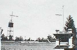
yard sale that eventually lead me to the discovery of Dodd's Wireless Station and also for keeping me informed about other Dodd items and photographs that other antique dealers had obtained.

References:

1. Manual of Wireless Telegraphy for the use of Naval Electricians, 1913 - Robison

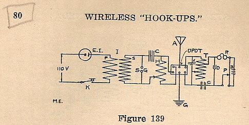
2. Wireless Hookups, 1911 - G. Rudolph

3. How to Make Wireless Instruments, 1912 - Various Writers

4. Construction of Inductance Coils and Transformers, 1912 - H.W. Secor

5. Electro Importing Company, Catalog #2, 1910

6. Wireless Telegraphy & High Frequency Electricity, 1909 - H. Lav. Twining

7. M.H. Dodd Photographic Album - 1910-1917

8. Sierra Magazine, Special Issue 1963, "Men Who Match Our Mountains"

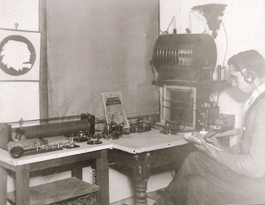
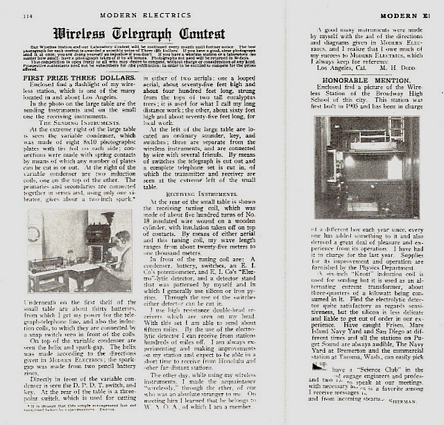
9. Modern Electrics, June 1909 issue, Article on Dodd's 1909 Wireless Station - accessed from Google Books - Thanks to Chris Props KJ4RGH for the info on this article

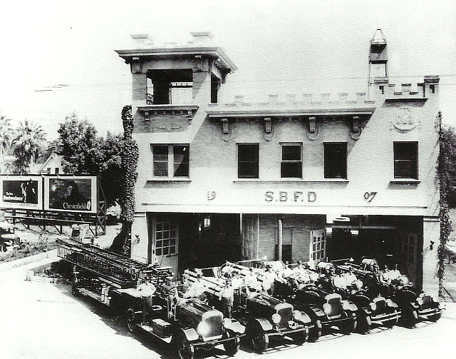
10. Images of America - San Bernardino Fire Department by Steven Shaw - 2003 - History in vintage photos of the SBFD


Copyright © Henry Rogers  July 27, 2000

Revised, edited and additional info added:  December 9, 2001, July 30, 2002, July 2007

Completely revised, new written material, re-edited, new photos added - © Henry Rogers May 29, 2009

New material added - July 2011

New material added - December 2013

New material added - December 2015

Re-edited for new layout - March 2019


Appendix

Other Dodd Radio Projects

M. H. Dodd's Version of the 1923 Cockaday DX Regenerative Receiver

In the January 1923 issue of Radio Broadcast magazine Laurence Cockaday presented an article describing what features were necessary for the radio amateur or radio broadcast listener to have in a radio receiver for successful DX reception. Cockaday's article also contained plans for building his "DX Regenerative Receiver." Laurence M. Cockaday was a well-known radio engineer and author of several popular books on "Radio" who also had several types of radio circuits published that were incorporated in commercial radio manufacture and ultimately ended up becoming the Editor for "Radio News" magazine in 1931. The DX Regenerative Receiver circuit Cockaday presents in the Radio Broadcast article is a three-circuit tuner regenerative detector with two stages of audio amplification. It was important the the builder of this receiver closely follow the instructions because much of the ability of the receiver to "autodyne" and not have hand-capacitance problems was due to the proper wiring of the variometer and the variable condensers connections to ground with a unique idea of Cockaday having the B+ to the detector plate tied to ground,... not B-,...ground (see schematic below.) Since the major regenerative components are tied to ground no hand-capacitance effects are encountered during operation of the DX Receiver. The plans also show that the two interstage transformers should be mounted at right-angels to prevent magnetic coupling. It's interesting that Cockaday goes into great detail about the wiring layout saying that the builder must avoid the "beautiful buss-bar wiring" with long runs with many right-angle bends. His comparisons of buss wiring to walking up a street and turning down another street and up another street or the comparison to horse and buggy reins are dated analogies but none-the-less correct if the builder is to avoid stray coupling problems in the receiver that would spoil its ability to "pull-in DX". The plans not only have the schematic but also plans for the cabinet, chassis and mounts included.

Dodd's version of the Cockaday DX Regenerative Receiver is surprisingly close to the plans even though Dodd uses different manufacturer parts. For example, the plans list a Tuska molded variometer but Dodd uses a Gilfillan Bros. molded variometer. Since Dodd was located in the Los Angeles area (as was the Gifillan Bros. plant,) Gilfillan parts are used to a great extent in his version. The dials, the tube sockets and the rheostats are also Gilfillan parts. Dodd's version also features a variable grid-leak resistance using an Allen-Bradley compression resistance in the one meg-ohm range. It appears that the receiver originally used a fixed grid-leak since there's a mount for one but the variable resistance was added later. The panel features gold decals for identification of the control function and a fancy drilled pattern for viewing the vacuum tubes (to estimate filament voltage by how bright the filaments are lighted.) There are rheostats for each of the vacuum tube filament control that are 5 ohm maximum resistance. This implies that 1 Amp tubes are to be used in the circuit, a UV-200 soft detector and two UV201 hard amplifiers. (The average lead-acid battery at full charge would be around 6.7vdc with the average filament voltage per tube being around 4.7vdc giving an IR drop thru the rheostat of 2vdc at 1Amp requiring the rheostat to be set to 2 ohms - about half rotation on the rheostat.) The interstage transformers are "matched" American Transformer Company versions with the brown transformer being for the first audio stage and the black transformer for the second audio stage (factory-marked as such.) Dodd built his cabinet out of solid mahogany generally following Cockaday's plans.

This Dodd-version Cockaday DX Regenerative Receiver was included in the purchase of all of the "radio related" items that were at the 1999 Reno yard sale that was put on by Dodd's step-son. Now first, I have to say that at that time the Dodd-Cockaday receiver was in absolutely horrible condition. It had been infested with mice that seemed to divide their time between shredding the January 1923 Radio Broadcast magazine that was inside the receiver cabinet and defecating the end results of that shredding to the bottom of the cabinet. Also, the right side piece of the cabinet had been removed (by Dodd) so perhaps this allowed easy access for the rodent population over the years. For 17 years I never even looked seriously at the Dodd-Cockaday receiver, in fact, at one point I had traded it to fellow radio-collector Roger Sannapoli but he traded it back to me after emptying the shredded paper into a garbage can and seeing the mess that was still left in the cabinet. At that point (Jan 2016,) I decided to go ahead and see if the receiver could be restored. Luckily, the mice must have been content with their paper diet since none of the circuitry was touched. Of course, the inside-bottom of the cabinet was disgusting and had to be wet-cleaned and disinfected outside the house. A quick check found that both interstage transformers were okay as were the three rheostats. The variometer needed some cleaning as did the primary-secondary inductance. Everything needed a thorough cleaning with Glass Plus and various brushes. The two large variable condensers needed detailed cleaning since some contamination was between the plates. However, this is water-soluble stuff that was pretty easy to clean out using long hair brushes and lots of Glass Plus.

Test Set-up - The DX Regenerative Receiver was designed to run on batteries. Then the connection of detector B+ to ground won't conflict with the B- buss that is not grounded. A "floating" antenna-ground was common in battery operated radios but connecting the detector B+ to ground was a unique idea. Since I was going to power the DX Receiver on power supplies, I had to make sure that there was no coupling of the Ground connection to B- which in some of the power supplies are tied to chassis and to AC ground. The best way with the DX Receiver was to connect a .1uf capacitor between the Ground terminal and the AC house ground. I then powered up the DX Receiver using a 6vdc 4A Lambda supply for the filaments, an adjustable 0 - 30vdc 2.5A Lambda for the detector B+ and an RCA Duo-Rectron B Eliminator for the +90vdc B+. Since pure tungsten tubes are used in the receiver, these tubes must be in good condition. Many UV-200 and UV-201 tubes will have good filaments and illuminate just fine but have no emission and thus no gain. UV-200 tubes are highly variable and may require anything from 4.0vdc to 6.0vdc on the filament to get decent performance. These tubes have some Argon gas inside the envelope and this has to be heated to develop the properties that make it act as a "soft detector" which takes about 5 minutes of operation. Being able to vary the B+ helps to find the best compromise between lowest filament voltage versus the best level of B+ for the most sensitive detection. Best sensitivity is usually achieved after a 5 minute "warm up" period and then adjusting the detector plate voltage in the range of +15vdc up to around +25vdc while leaving the filament voltage set to the lowest voltage where the tube is performing well. This preserves the tungsten filament which has a finite emission life.

Lack of Performance and Critique of Cockaday's Circuit - Performance of the DX Regenerative Receiver is disappointing. Cockaday's connection of the variometer is the problem. The instructions are very specific to wire the rotor to the detector plate and the stator to ground (B+ in Cockaday's circuit.) If the variometer is connected per the instructions the detector will not regenerate. A check of the variometer confirmed that the various coils were in series as they should be. Connected opposite from the instructions, e.g., with the rotor connected to ground (B+ in Cockaday's circuit) and the stator connected to the plate, the detector does oscillate. But, connected as Cockaday indicates, no oscillation can be achieved. Various connections, tubes and voltages were tried and various relationships between the variometer rotor and stator were tried but only when the variometer is connected opposite of what is shown and described in the article does regeneration happen.

As to what the variometer does in a regenerative detector circuit,... the variometer will have variable total inductance (L) which can be a positive sign (+) or a negative sign (-) depending on the rotor coil position. Maximum total L occurs when the axis of the rotor coil and stator coil are parallel to each other. The total L decreases to 90deg  rotation in a + sign and then increases total L as the rotor is further turned to 180deg. The next quadrant of rotation decreases total L again but as a - sign with minimum - sign total L at 270deg and further rotation increases -sign total L to 360deg or 0deg.  The total inductance sign is what allows the detector to oscillate when the plate to grid capacitance and the variometer are "in tune" at the selected frequency of operation. An improper relationship of the rotor and stator can cause the detector to not regenerate or to regenerate uncontrollably. The usual operation has regeneration take place between 0deg and 90deg of the + sign of total L change. This is the maximum amount of total L change and that's what is tuning the plate circuit of the detector. The regeneration occurs when the grid to plate interelectrode capacitance and total L of the variometer are resonant with the tuned frequency of the detector grid input.

I decided to check the regenerative detector receiver variometer on two other sets, the Kennedy 220 and the Radiomarine IP-501A, to see how those sets connected the variometer to their detector tube. What I found in both receivers was the stator was connected to the plate and the rotor to B+, just the opposite of what Cockaday instructs for the variometer circuit connection. I'm sure other regenerative detectors are connected in the same manner as the Kennedy sets and the IP-501A. Cockaday claimed the stator coils connected to ground (B+ in Cockaday's circuit) made the tickler control immune to hand capacitance effect but if the detector won't regenerate one wouldn't have hand capacitance problems anyway.

It really doesn't matter that the DX Receiver doesn't work as the article indicates. The DX receiver's performance is its history and I must keep the receiver original to the instructions and original to Dodd's construction even if that results in a poor performing receiver. Its performance certainly must have been a disappointment to Dodd after all of the obvious work that was put into building the receiver.

Now, all of the above criticism isn't to say that the DX Receiver doesn't work at all - it does work - just not as well as one would expect from a regenerative detector. Since it won't regenerate, it performs like a grid-leak detector with two stages of AF amplification which isn't very impressive. Local stations are received fine but this circuit is no DX receiver.

H. Rogers Jan. 2016


Return to Home Index


Radio Boulevard
Western Historic Radio Museum

 Vintage Radio Communication Equipment Rebuilding & Restoration Articles,

 Vintage Radio History and WHRM Radio Photo Galleries

1909 - 1969

- 60 years of Radio Technology -


This website created and maintained by: Henry Rogers - Radio Boulevard, Western Historic Radio Museum © 1997/2023