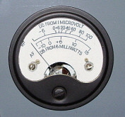
photos left: Before and after showing the early RF/AF Level Meter scale restoration. Staining of the paper scale can be seen in the before photo (SP-600 JX-21).
|
Radio Boulevard
~ Cosmetic Restoration ~ ~ Performance Expectations ~ ~ Collector's Gallery of SP-600 Photos ~
|
|
PART 3 |
|
Cosmetic Restoration of the SP-600 |
| Front
Panels - The front panel of the SP-600 is pretty easy to
remove and it should be stripped of the dial escutcheons, the plastic
window for the band switch dial and the meter so that you have just the
panel itself. Cleaning can be done with dish soap and water or any other
sort of mild cleaner. I avoid using Windex because it has ammonia as its
active cleaner which can remove some kinds of paint used for panel
nomenclature. Glass Plus which is ammonia free seems to work very well.
Most panels will have some chipping that can be touched up using matched
paint. The panel can then be lightly polished or waxed if desired since
the original paint is super tough. Repainting the Front Panel - This should only be done if the panel is really in poor shape and doesn't look very good after cleaning and polishing. First, if you want to maintain originality, have the front panel paint matched at an automotive paint shop. This way you end up with high quality paint that's the correct color. Many automotive paint stores will fill spray cans with the matched paint for a nominal fee. This makes painting the panel much easier. One can is usually more than enough paint to do a single front panel about three or four times. You probably will have to spray the panel at least twice since usually the first try will have too much paint applied. The original paint is very, very tough and will require a couple (at least) applications of heavy-duty epoxy stripper. Make sure the panel is super clean and degreased. Original SP-600 panels look like they didn't use a primer and since you are going to have to fill the engraving you don't want to have anything that is going to add more paint than is necessary. Spray a couple of coats and see how the engraving looks. If it's still pretty sharply defined and the panel coverage looks good then stop. Too much paint will fill the engraving and prevent proper nomenclature filling. Two coats should be the maximum. Let this dry for at least a day or two. Most automotive paints will "shrink" somewhat while drying. At first the nomenclature will look like there is too much paint applied but wait a day and see how the paint is after it has fully dried. |
Nomenclature Fill - For the nomenclature fill, I mix Artists Acrylics of White, Raw Sienna and a little Black to end up with a Manila color. "Pure white" will look way, way too bright. Do only one or two sets of engraving at a time. Apply the paint with a brush into the engraving and you don't have to be real careful - just paint it in. Let the paint set for about one minute. First remove the excess paint using a squeegee. Then use a small piece of paper towel folded a couple of times that has been dampened (not dripping wet) with Glass Plus. Don't use Windex - only Glass Plus works for removing the excess fill paint without damaging the panel paint. Lightly rub the dampened paper towel in a circular motion with the paper towel absolutely flat on the panel. As the excess paint not removed by the squeegee is beginning to come off, flip the paper towel over to the clean side to continue to remove the excess paint. I always have several pieces of towel ready because you'll need at least two pieces (four sides) to remove the excess paint. Let the paint in the engraved area set for a few minutes more and then wipe the area down again with another dampened paper towel to fully clean the area I usually have to apply some more fill paint and repeat the process to get the lettering to really look professional and proper. Let the fill paint dry for a day. Finally, use carnauba wax and apply a nice polish to the panel. It will look great. |
|
Chassis Cleaning with Easy-Off Oven Cleaner - SP-600
receivers were normally used in controlled environments during their
active lives. However, most of the receivers have now become victims of
poor storage in humid areas such as garages, basements or worse - sheds.
The moisture damage to the aluminum usually shows up as oxidation and
dullness to the finish or, worst case, pits. This kind of damage can be
somewhat removed by using Sodium Hydroxide. A convenient way to apply
Sodium Hydroxide is with Easy-Off Oven Cleaner (EOOC.) Spray a small amount of EOOC into a cup and using an acid brush or Q-Tip, apply a coating to the chassis. EOOC does react with aluminum but you aren't going to leave it on the surface for more than just a few minutes. Wipe off the EOOC and then swamp the area with water using either a brush or Q-Tip. Gently wipe and repeat the water rinse a few times to neutralize the EOOC. Application of the EOOC should be performed in a well-ventilated area. The surface aluminum will be left very clean AND will have the flat finish of the original aluminum. This treatment leaves the aluminum very clean but doesn't "polish" or scratch to remove the oxides and dirt. >>> |
>>> Nobody wants a "polished to a mirror" finish on a receiver
chassis. Most restorers want the aluminum chassis to appear as it did
when the receiver was fairly new. The EOOC treatment ends up with the
aluminum looking "flat" original. The IF transformer shields and all of
the the other removable aluminum pieces including the side gussets can
be taken outside and, one at a time, sprayed with EOOC, left for three
minutes and then rinsed with water from a hose. This ends up with the
aluminum pieces looking very clean and with a flat finish like they had
when they were new. Be sure to rinse all the pieces thoroughly with
water. Also, don't rub the aluminum pieces with anything - just let them
air dry. Rubbing will actually end up slightly polishing the aluminum
piece and will ruin the flat finish you are trying to achieve. When
cleaning the IF, BFO & T-1 shields, be careful of the lettering on top
of the cans. The lettering is very delicate and almost any cleaner seems
to destroy it. Avoiding the lettering works best. This EOOC trick only
works well on aluminum. It doesn't have too much of an effect on steel -
it cleans (as it's supposed to clean your oven) but that's all. Components like the power transformer and the chokes can be cleaned with any mild cleaner then touched-up as necessary. If they look a little dull, they can be given a coat of Armor-All. |
| Tuning, Logging
and Band Indicator Dials - There are three dials on the
SP-600, the main tuning dial, the logging dial and the small band
indicator dial. The paint on these looks durable but it's common to find
the paint cracked and flaking off. Also, staining from excessive
moisture encountered during poor storage conditions is common. You'll
have to test a small area of the dial paint to see how well it is
adhering to the dial base. I use a small paint brush and gently brush
the area and look to see if I see flaking. This is a sign that the dial
paint is beginning to crack due to surface corrosion on the dial base.
If you don't see any residue coming off with gentle brushing then the
dial paint is in good shape and can be cleaned very gently with a damp
cotton cloth. Some dials will be found with the paint already falling
off and with surface corrosion apparent in the areas missing paint. It appears that the original method used to finish the dials was to chemically apply a black oxide coating to the dial. This might have been black anodizing but it could also just be an oxide treatment. Next, the white paint was applied into the areas that are to be the background color. This had to be a relatively slow drying paint that was allowed to settle leaving the high points - the dial numerals - slightly above the paint. Then a squeegee type of device skimmed the high points to reveal the black oxide underneath. I haven't tried this method of dial restoration since spare original dials are so expensive and I don't want to take a chance on ruining a decent set of dials. However, I do now have a spare set of SP-600 dials that are in poor condition and sometime in the future I'll attempt this type of restoration. For the time being though, the only accepted solution for poor condition dials is a photo paper overlay that is glued to the back of the dials and then reverse mounting the dials. These never look original and are only a "stop-gap" solution until good condition original dials are found or someone develops a good restoration method for the SP-600 dials. |
| Dial Pointers - The dial pointers have a black oxide finish on them. Sometimes they have scratches but touch up is easy with a black marker pen, like a "Sharpie," which gives the sort of "transparent" look that the original finish had. The main tuning dial pointer can be removed with two small screws while the upper pointers can be removed by dismounting the dial lamp assemblies. | Escutcheons and Plexiglass Screws - The escutcheons seem to take a lot of hits and are usually scratched up. Repainting is sometimes necessary but usually they will touch up fine and look more original that way. I use satin black spray paint that is sprayed into a small cup and then applied with a very small brush. The satin black seems to blend better than gloss, even though the escutcheons are somewhat glossy. If you've repainted the front panel, you'll probably want to repaint the escutcheons, too. Be sure to use high quality automotive paint as this will give the absolute best results for your repaint. The screws that hold the plexiglass dial covers always seem to be rusty. Just wire brush and paint with flat black paint. Don't torque these screws tight or you'll crack the plexiglass. Just barely snug is all that is needed. |
|
|
|
RF/AF
Level Meter - The RF/AF Level Meter on the early SP-600
uses a paper scale that is very prone to moisture damage since the meter
itself is not a sealed unit. If the scale is really stained badly, it
can be removed and covered with a reproduction meter scale. You can make
your own repro scale if you can scan the stained original scale into a
computer. Disassemble the meter and remove the scale. Scan the scale
into the computer. Use a "photo editor" program to correct the defects.
Sometimes the discoloration is too severe to easily remove in the photo
editor. In that case you can try making successively lighter copies (on
a copy machine) of the scale until the nomenclature remains but the
color background is even. Then scan that copy into the computer and
photo edit out any remaining defects. Size it correctly and make the
final print out on photo paper that is non-gloss finish. I specify photo
paper for a fine texture finish and clean printing. The final scale copy
has to be lightly glued over the original scale backing. When the meter
is reassembled make sure the needle doesn't drag on the new scale since
it is now a little thicker. Also, clean the needle stops of corrosion
(common problem.) When the entire meter is together it is very difficult
to tell that the meter scale is not original - except that it looks a
lot better than most originals do. The later Marion Electric meters are
much higher quality and use a paint-on-metal meter scale. photos left: Before and after showing the early RF/AF Level Meter scale restoration. Staining of the paper scale can be seen in the before photo (SP-600 JX-21). |
| Cabinets - Most SP-600s were rack mounted, usually in multiple receiver set-ups. Originally, the SP-600 could be ordered as a "table mounted" receiver with cabinet. The table mounted receivers did not have bottom covers since the cabinet provided the same function. It was possible to order a conversion kit to convert a table receiver to a rack mount. Although it is mentioned in the manual, it seems likely that someone could have ordered a cabinet from Hammarlund to convert a rack mount to a table mount. Since most receiver were in racks, there are more receivers around than original Hammarlund table cabinets and this has resulted in the original cabinets becoming fairly high priced. Since the SP-600 has a very deep chassis only a few types of non-Hammarlund cabinets are deep enough to house the receiver. The original cabinets do not have threaded holes for mounting the panel of the receiver to the cabinet. Instead, a drilled and tapped metal strap fits behind the panel mounting flange and then the panel screws thread into the strap. There are also a couple of holes in the bottom of the cabinet to allow securing the back of the chassis using the tapped mounting brackets that originally hold the bottom panel on. >>> | >>> Cabinets are usually wrinkle finished and can be found in several different shades of gray ranging from light grayish-brown to dark charcoal gray. The cabinets can be cleaned with Glass Plus and a soft brass brush, like a suede brush. Soak each surface in turn with the Glass Plus and then work the brass brush gently in a circular motion to work the dirt and grime out of the wrinkle convolutions. Wipe the area with a paper towel and repeat until the paper towel wipes are fairly clean. Don't scrub too long as the paper towels will never be perfectly clean and you are really seeing some "dead" paint as color on the towels. Usually two applications is enough. Let the cabinet dry thoroughly and then do any touch-up that is necessary and let that dry. Finally, apply either Armor-All or 10W Machine Oil (not both) and wipe off the excess. The cabinet will look beautiful. |
|
SP-600 Performance Expectations |
| The SP-600 performance is
legendary. However, many hams who have heard or used an SP-600 in the
past were exposed to a receiver that was not operating at its full
capabilities. The receiver was designed to somewhat function will
several defective parts, weak tubes and poor alignment. A newly rebuilt
and freshly aligned SP-600 returns the receiver back to operation that
is at or better than the original specifications. When everything is
working correctly on an SP-600, you'll find it's a fabulous receiver
that is a pleasure to operate and even more of a pleasure to listen to.
The large knobs impart a great feel to the operation and the
ultra-smooth tuning adds to the enjoyment of searching for stations. The
sensitivity of a properly aligned SP-600 is impressive and, with a
matched antenna, you'll hear everything that is on frequency with
conditions or QRM being the only limitation.
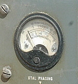
The selectivity is very good at the 3kc position for SSB and CW signals. AM signals can have the bandwidth expanded to 8kc and if the station is very strong, try 13kc for the ultimate in wide bandwidth audio response. The Crystal Filter has it critics but I find that it works very well on CW but even SSB or AM can benefit from its use when adjacent frequency interference is a problem. Accurate alignment of the crystal filter is crucial for its proper operation. Selectivity is very sharp in the crystal filter position and you can also vary the phasing from center to reduce heterodynes or peak CW signals. Many users (or maybe potential users) feel that the tuning dial's vague readout accuracy is the main drawback to the receiver and generally you'll find these critics comparing the SP-600 to the R-390A. These two receiver's utilize design approaches that couldn't be more diverse - not to mention that the R-390A cost was at least two times that of the SP-600. The SP-600 covers large slices of the spectrum in each tuning range. You just couldn't get one kilocycle accuracy when each tuning range covered several megacycles. The only way Collins could get 1.0kc accuracy was to limit the coverage of each tuning range to one megacycle. If you want a 30 band receiver, you can have the 1.0kc accuracy. The SP-600 allows rapid coverage of wide areas of the spectrum - something necessary for certain kinds of surveillance. |
|
| The logging scale was provided to allow a means of
accurate resetability and its use will really help in finding net
frequencies for monitoring. Once you've found the net, make a note of
the logging scale reading and you'll always be able to retune right to
the correct frequency. Or, you can always use a heterodyne frequency
meter if you want to know exactly where you are tuned - that's
the way they used to do it before digital frequency readouts. As mentioned elsewhere, the Crystal Controlled Switchable Oscillator - the "X" option - is rarely used. It requires specific crystals for the desired tuned frequency and then you still have to tune the receiver to the desired frequency so that the RF stages and the Mixer are in tune. The typical SP-600 doesn't drift after a 10 minute warm-up. The SP-600's audio quality is highly subjective with some users finding it to be standard "communications grade" with no bass response while others listeners find the audio to sound "high fidelity." The stock bass response is rolled off so that the 3db point is at about 125hz resulting in a mild bass at best. Stronger AM stations will have some depth to the audio (depending on your speaker.) AM ham stations that are running some power sound pretty good and the retired AM BC transmitters operated on 160M or 75M will sound best. Be sure to match the 600 ohm output for the best audio reproduction and use a large speaker in a good enclosure. The audio has a lot of highs when the bandwidth is in the 13kc position. In the 13kc position you will note that the IF gain is slightly reduced, this is normal and part of the design for best audio reproduction with expanded bandwidth. Major audio modifications to greatly enhance the bass response are not recommended as this will seriously alter the receiver's capabilities for CW and SSB reproduction. Minor shaping of the audio will improve the response while still preserving the receiver's performance in modes other than AM. >>> |
>>> The calibrated BFO can be very accurate and very handy for
SSB. You do have the capability of selecting upper or lower sideband by
which side of "0" you set the BFO. Drift is just about non-existent
after about a 15 minute warm-up. To set the BFO to the correct sideband,
first tune in the SSB station to "zero beat" or where the audio sounds
"muffled and bassy" - then, by adjusting just the BFO to one side or the
other of "0," the audio will clear up and sound normal. Whichever side
that is will be the correct setting for whatever sideband that station
is using and more than likely for all the SSB ham stations on that
particular band. The SP-600 will provide excellent SSB audio. And you don't need a Product Detector or a CV-591-type of external SSB IF unit either. Good SSB demodulation requires that the detector has the proper ratio of BFO injection to the incoming signal level. Best audio will require that the AVC is in the OFF position and that the RF gain control used to set the correct ratio. Turn the AF gain up to 6 or 7. Turn the RF gain to a level where the incoming received background noise is moderate - usually about 5 or 6. Selectivity should be on 3kc. With an SSB be signal tuned in, lower the RF gain if the audio sounds distorted. At the proper RF gain setting, SSB signals sound great on the SP-600. The disadvantage is that every signal has a different strength and the RF gain usually has to be adjusted each time. With "one on one" QSOs, it's usually not a problem but Net Operations, with many different stations "checking in," can be somewhat frustrating. You can operate with the AVC on to limit the maximum sensitivity (with the RF gain set to about 7) but strong SSB stations will probably still distort. Most versions of the SP-600 provide an adjustable BFO Injection adjustment located on the rear apron of the receiver. This can be adjusted to a higher level if you plan on mostly SSB reception rather than CW, although the highest level is still a lower injection level than what is required for SSB demodulation with high level signals. Low-level BFO injection was normally used for CW signals and prevented "masking" of very weak CW signals. Some modifications will increase the BFO coupling capacitor value to increase the total injection level at the detector but this is really unnecessary since it's much easier just to reduce the RF gain level. >>> |
|
|
By using the ham station antenna you will be providing
the SP-600 with a matched antenna that will allow it to perform at its
best. Many casual listeners using unmatched end-fed wires may be
disappointed at the SP-600s performance, especially when considering the
high noise levels experienced with end-fed wires. The SP-600 was
designed to operate with a matched antenna and this set up will give the
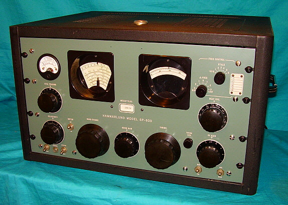
best performance results. Most SP-600 versions will have a RELAY socket that looks like an AC receptacle. This parallels the SEND-REC switch and allows the receiver to be put into stand-by remotely. This can be done with the auxiliary contacts on a Dow-Key type relay and it makes using the SP-600 as the station receiver very practical. Be sure to leave the SEND-REC switch in the SEND position when using the remote stand-by function. An exception to this RELAY socket is the popular SP-600 JX-17, which, since it was for diversity reception, does not include a remote standby option. While the SP-600 may not provide the dial accuracy of an R-390A, you won't strain your wrist tuning in stations while band cruising. You'll hear the same stations that the R-390A would receive and they may even sound a little bit better (but probably not). photo left: 1953 SP-600 JX21. I've owned this receiver for many years and it has undergone several restorations during my ownership. At one time I even painted the front panel green (see photo in Collector's Gallery below.) I recently found an SP-600 "parts chassis" that provided a mint condition set of dials, a good working Selectivity switch and many other minor parts that allowed a proper restoration back to "stock" appearance along with great performance. I had the front panel paint matched from the SP-600-25C receiver and it is an automotive type acrylic enamel paint. I also returned the cabinet color to the standard gray. I've also replaced the CL meter with a better example. |
|
Collectors Photo Gallery of SP-600 Receivers |
|
|
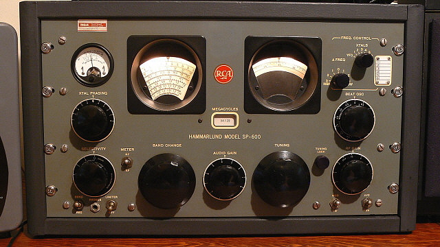
SP-600 JX from the RCA David Sarnoff Research Center This incredible SP-600 is owned by Jeff James W2NBC. It was purchased by RCA's David Sarnoff Research Center in 1957. Since the panel is RCA Umber in color and the cabinet is also the grayish-brown that RCA used in their equipment, it seems likely that this receiver was part of a special order from Hammarlund and painted in the RCA colors. The RCA "meatball" logo is fifties vintage but the tag in the upper left corner uses the later "block" RCA letters (came about in 1964.) There was also a calibration tag above the RCA meatball that was last dated in the sixties. Jeff has restored this special SP-600 but the panel is original paint. The cabinet was matched to the original color found under the grab handles. |
|
|
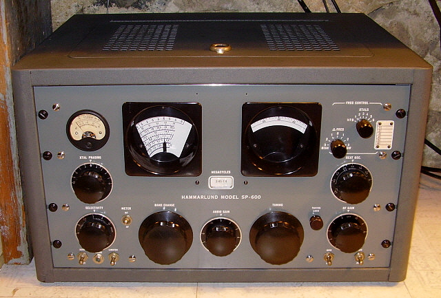
SP-600 JX-14 SP-600 JX-14 with a light gray panel and black nomenclature. Photo from eBay. |
|
|
SP-600 JX Though this SP-600 is in fairly rough condition one can't help noticing that the front panel has been painted light blue and the dial escutcheons painted dark blue. Photo from eBay |
|
|
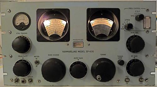
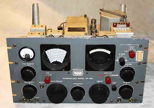
SP-600 JX-17 SP-600 JX-17, standard configuration. The JX-17 was probably the most produced version of the SP-600. It was designed specifically for diversity operation and has a slightly different AVC system because of that. The red knobs are only found on the JX-17 version. Photo from eBay. |
|
|
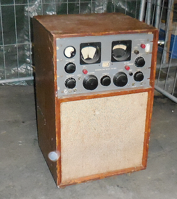
SP-600 JX-17 Console Here is a SP-600 JX-17 that is installed into a wooden console made out of plywood that has been stained and finished. The large speaker area is integral to the cabinet and the receiver is mounted from the front into its area. This SP-600 console is in Berlin, Germany and was used by the US Army "Berlin Brigade," possibly at Andrews Army Base where it was placed in the soldier's dayroom as an "entertainment radio." The photo is from Nicolas von Moellendorff, who is the current owner. Nick obtained this SP-600 from the last manager of the US Army Laundry in Berlin. It has a 120vac to 240vac transformer external to the receiver for operation on European line voltage (and interfacing to Euro-plugs and receptacles.) Nick had a small museum in Berlin for US Army items and equipment. He currently has a militaria website. The URL is www.berlin-military.com |
|
|
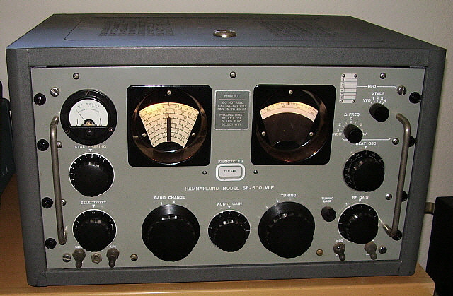
SP-600-VLF-31 The SP-600-VLF-31 receiver tunes from 10kc to 540kc and is built along the lines of the HF SP-600 receiver. The "VLF" is NOT a SP-600 with LF coils installed in the turret. It is a completely different circuit designed specifically for low frequency operation. First, it's a single-conversion superhet that is using 705kc as the IF. It does employ two RF amplifiers in the front end and uses a total of 21 tubes. There's a 1160kc conversion oscillator circuit that mixes with the 705kc IF output to provide a 455kc IF output to run RTTY or similar devices. The Xtal oscillator has four positions and uses FT-243 crystals. There are only five selectivity positions and all of them go thru the dual stage crystal filter. Four IF amplifiers are used. While there are significant differences in the circuit, the construction and most of the mechanics are the same as the HF SP-600. Turret band switching, same dial drive system, similar layout, etc. The side panels are similar to the R-390A receiver and don't have the typical SP-600 "pylons." The chassis and side panels are gold iridite finish. What about performance? If you're familiar with how vintage, high-performance VLF receivers operate and you are located in a RF-quite area and you're using a good design loop antenna (either remote tuned or shielded magnetic,) the SP-600-VLF-31 is an unbeatable LF receiver. I've logged well-over 250 NDB (Airport Beacons) from all over North America with this receiver operating with a six-foot remotely tuned loop antenna. The SP-600-VLF shown was built in 1958. A lot more detail about this SP-600VLF-31 is in the write-up in "Vintage Long Wave Receivers Part 3" - use the Home-Index to navigate See (further down this page) the photos for "WA7YBS 75M & 630M Station" for how this receiver is being used currently (2018.) |
|
|
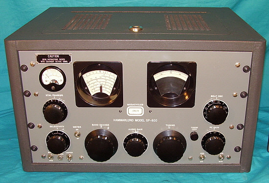
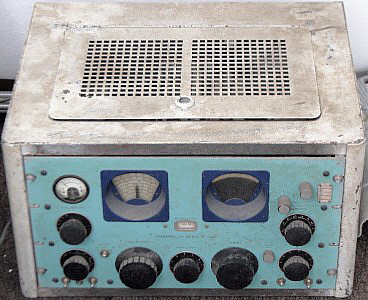
SP-600 JX-21 Here's a photo of a JX-21 with a front panel that I painted Hammarlund green. The color was matched to an old BC-1004 (SP-200) receiver so there would be some connection to an actual Hammarlund paint color. Although the receiver looked great and worked fine, a couple of museum visitors actually asked if the SP-600 was a Heathkit product - I was flabbergasted! After that, I had to return the panel to original Hammarlund SP-600 gray. The appearance now of this SP-600 JX-21 can be seen in the photo in the "Performance Expectations" section above and in the header photo at the beginning of this article. The cabinet looked like an original black paint job but after removing one of the rubber feet, I noted it was a repaint and the original color had been gray. I have also returned the cabinet back to its original color. |
|
|
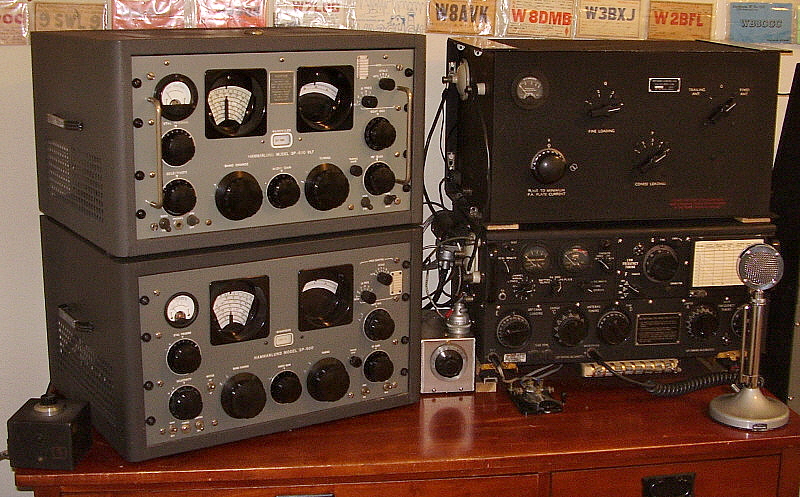
WA7YBS 75M & 630M Station The station consists of two Hammarlund SP-600 receivers. The top receiver is the SP-600VLF-31 tuning from 10kc up to 540kc. The bottom receiver is the Hammarlund SP-600 JX-21 tuning from 540kc up to 54mc. The small box to the left of the JX-21 is the remote tuning for the six-foot loop antenna used on 630M for reception. The HF receiver output is to a floor speaker. The LF receiver output is to 600Z ohm 'phones. The transmitter is an ART-13A with O-17/ART-13A LFO installed allowing operation from 200kc up to 600kc. On top of the ART-13A is the CU-32/ART-13A Antenna Loading Coil. The CU-32 allows the ART-13A to match a variety of antenna types on LF. Both the HF output and the LF output from the ART-13A are routed through the CU-32. The output of the CU-32 is connected to the HF antenna when "FIXED ANT" is selected and is routed to the 630M antenna when "TRAILING ANT" is selected. The silver box to the left of the ART-13A is an auxiliary condenser that aids in loading the transmitter on 75M. The J-38 hand key is for LF-CW and the mike is for HF phone. LF transmitting antenna is an end-fed wire 163 feet long. HF antenna is a 135' CF Inv-vee with 96' of ladder line to a Viking KW tuner. Unfortunately, I had to disassemble this station. A new "modern, efficient, modulated" furnace that has a "smart" thermostat doesn't like any type of RF field near it. Especially RF in the MW spectrum. I have to move all 630M operations out to the shop and that hasn't happened yet.
|
|
Conclusion |
| More
Information Wanted: We always try to present the most
accurate information available. We depend on Hammarlund SP-600
collectors, restorers and fans to provide information or corrections for
this article. This results in accurate information that helps all
enthusiasts in the preservation and operation these marvelous receivers.
We are looking for the following information.
1. Want to add your SP-600 rebuilding experiences, ideas or photos? I always give full credit for your contributions if I incorporate your info into this webpage article. Performance thoughts? 2. If you have an original SP-600 that has a panel painted some color other than Hammarlund gray, send a photo. I would like to have better confirmation that other panel colors can be found and that they were original. I've seen original (or at least vintage) green and also khaki but don't have photos. For Sending You SP-600 Photos or Other Information - Here's the e-mail link: WHRM - SP600 INFO
If you want to know more about how the SP-600 came into being by reading about its "older brothers" (the Hammarlund SP-600 predecessors,) read our article "The Incredible 'Super Pro' Receivers" which details each of the early Hammarlund models - the Comet Pro, and all of the pre-war Super Pros, the SP-10, the SP-100, the SP-200 and the post-WWII SP-400 receivers, along with the WWII Military versions, the Power Supplies plus lots of other Hammarlund information. Navigation link in Home Index. If you are interested in Hallicrafters' Super Pro version , the R-274, go to "Hallicrafters' Super Pro R-274 Receiver" where, after reading the article, you can vote on whether your favorite receiver is the Hammarlund SP-600 or the Hallicrafters' R-274. The vote tally is presented at the end of the article.
|
| Henry Rogers WA7YBS © December 2009, more info added January 2010, more info added August 2010, re-edit June 2011, Dial Slippage additions, 630M station addition April 2018 |
| SP-600 PART 1 SP-600 PART 2 Return to Home Index
|
Radio Boulevard
Western Historic Radio Museum
Vintage Radio Communication Equipment Rebuilding & Restoration Articles,
Vintage Radio History and WHRM Radio Photo Galleries
1909 - 1969
- 60 years of Radio Technology -
This website created and maintained by: Henry Rogers - Radio Boulevard, Western Historic Radio Museum © 1997/2023