|
Rebuilding the Hammarlund SP-600 Series of
Receivers
General Information about the
SP-600
Hammarlund released an advertisement in 1948 that
introduced their newest receiver, the SPC-600X. The receiver was to sell
for $395 but, as Hammarlund had done before, this advertisement was
really just to let hams and interested commercial users know what was
going to be available in the future. No SPC-600X receivers were ever
created other than maybe a prototype or two. It was well-over a year later,
in 1950, that Hammarlund introduced the SP-600 Series and the selling
price had dramatically risen to nearly $1000. This new SP-600 was
primarily intended for the military and commercial user market. It was a
very popular receiver and many thousands were built, especially for
military applications. It's known that much of the
SP-600 design criteria actually came from the U.S. Army Signal Corps,
especially the JX crystal oscillator concept and the turret band
switching. The "JX" crystal oscillator wasn't new for the SP-600. The use of the selectable
crystal oscillator is seen on some "customized" SP-200 WWII Super Pro
receivers and was even designated as an "Improvement Kit" with the part
number MC-531 from the Signal Corps. Sometimes these receivers were "custom" rebuilds done by
various engineering companies for the Signal Corps. These "custom"
SP-200 Super Pro receivers usually date from 1947 up into the 1950s. The turret band changing was also a specification from the
Signal Corps and this is shown by the Hallicrafters' R-274 receiver,
built for the Signal Corps and sharing many similarities to the SP-600,
including the turret band switching concept. So, although Hammarlund
advertising appears to ignore the Signal Corps input, there's just too
much evidence available that shows much of Hammarlund's design concepts
for the SP-600 actually came from the Signal Corps. The first contract
issued was in 1950 for the R-483/FRR for the Signal Corps and was
actually a SP-600 JX-5 and was not actually built until November 1951.
The first built SP-600s were R-274A/FRR receivers (SP-600 JX-1) built on
a 1951 contract in September 1951.
Most SP-600 versions were built
throughout the 1950s but the SP-600 continued to be produced in smaller
numbers up into the early 1970s. The standard SP-600 tunes from .54 to
54MC in six bands. A "J" suffix indicates JAN parts were used in the
construction and an "X" suffix indicates a switchable crystal LO.
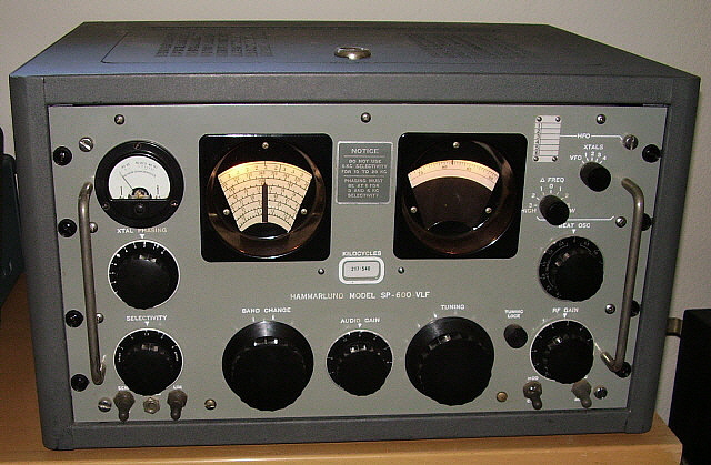
Hammarlund also offered a "JLX" version with 100-400KC substituted for
the .54-1.35MC band and a "VLF" version that covered 10KC-540KC. Hammarlund
made over 40 variations of the SP-600 that were each assigned a numerical suffix which
identified the particular circuit, mechanical changes or sometimes the
end-user. The last in the "time-line" was the model variation SP-600
JX-21A from 1969-1972 which utilized a product detector circuit, two
additional tubes and some other changes to make it "compatible" with SSB
operations.
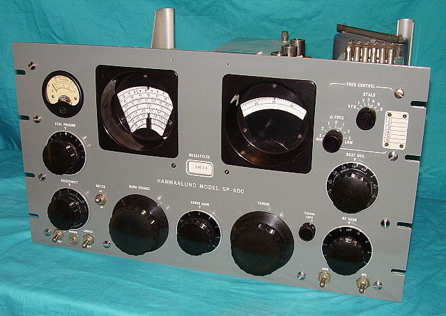
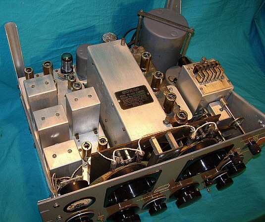
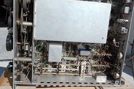
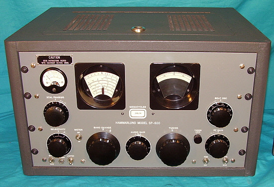
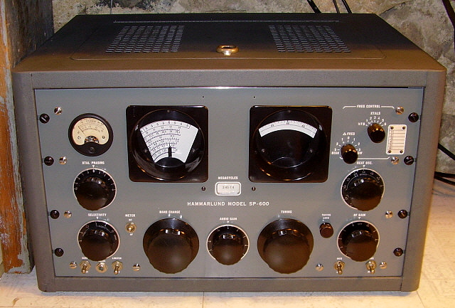
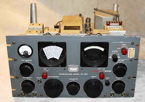
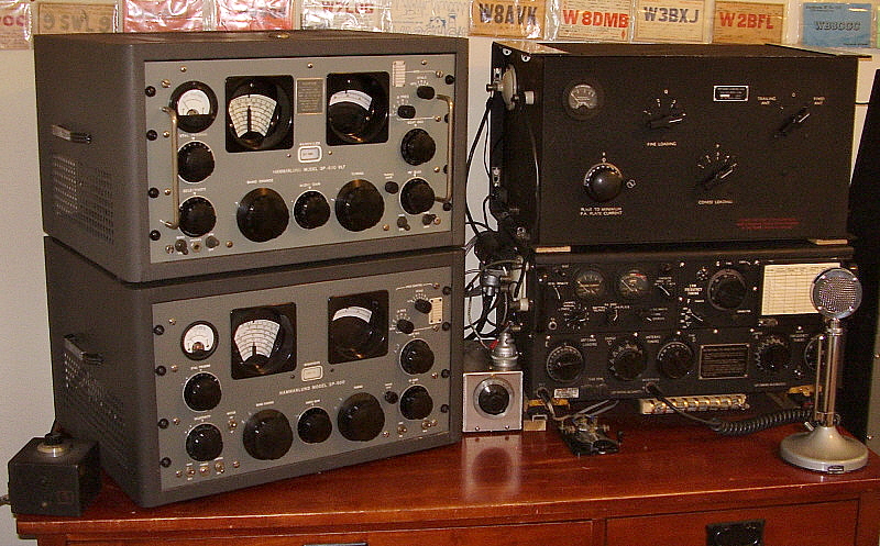
Most versions use a 20 tube double conversion
superheterodyne circuit with a rotating turret bandswitch. The receivers
also feature enormous proportions, robust construction and oversize
controls - along with a super-smooth tuning system that only adds to the
enjoyment of operating these fine receivers. Double conversion is
switched in above 7.4MC and uses a 3.5MC crystal-controlled conversion
oscillator. Though the SP-600 has two dials, it has no bandspread - the
right side dial is a logging scale allowing precise retuning of desired
stations. On the left is the main tuning dial and the mechanically
articulated dial pointer that indicates which tuning scale is in use
(along with the small window between the dials that shows which tuning
range is selected.) The tuning arrangement was an up-dated version of
the "Continuous Bandspread" system introduced in RCA's AR-88 series
receivers in the 1940s. The frequency readout accuracy is vague which is
why a precise logging scale system is incorporated into the SP-600
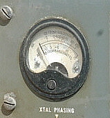
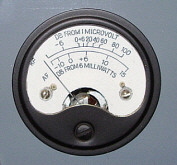
design. The Carrier/Audio Level meter is not illuminated and a switch is provided to
indicate either carrier level or audio output. Most (but not all) SP-600
model numbers usually will have a suffix with "J" or "JX" followed by a
numeral. As mentioned above, suffix "J" indicated that, as much as
possible, military level components and construction were used. Suffix
"X" indicated that a switchable six-position, fixed-frequency
crystal-controlled oscillator was installed that allowed the user to
install HC-6/U type crystals for specific desired LO frequencies. The
user could switch to any of the crystal LO frequencies for increased
stability for that particular frequency - however, the receiver still
has to be "tuned" to the desired frequency for the RF and Mixer stages
to be in tune. The number following the suffix generally indicates
specific features for that version, e.g., contract or end user, circuit
changes, etc., with the number ranges being more or less
chronological for introduction until the last of production. Though the
numbers assigned are chronological for their introduction, many of the
numbered versions were produced over a relatively long period of time
that saw many engineering changes incorporated into the receivers. As an
example, early 1953 JX-21 receivers are different from the 1956 USAF
documented JX-21 and both of these versions are very different from the
JX-21A of the late sixties. Many SP-600 receivers were set-up for
diversity operation and the standard diversity model was the JX-17
version. This version was produced in large numbers and can be easily
spotted by observing that it has two extra controls and uses three red
colored knobs. The SP-600 Audio output is about 2 watts from a single
6V6 using a balanced split-winding audio output transformer for 600 ohms
Z. A rebuilt SP-600 will provide an impressive "communications grade" type
of audio reproduction.
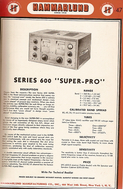 |
Shown in the photos left and right are two advertisements
for the SP-600. On the left is the initial 1948 ad for the
Series 600 "Super-Pro," the SPC-600X. This was a "teaser" ad to
show what Hammarlund was working on. It's possible that a
prototype or two may have been made but the SPC-600X was never
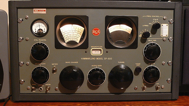
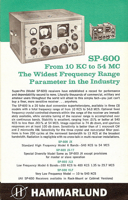
released as a sellable product. To the right is an ad for the
SP-600 from 1963. By this time, Hammarlund was owned by Giannini
Scientific Company and the products were built at Mars Hill,
North Carolina. Note that the 1963 ad promotes the SP-600's wide
frequency range (although you would have to buy two receivers to
have the advertised coverage.) Also note that by 1963, it appears that only
four SP-600 versions are being produced.
The influence of the earlier Super Pro receivers on the
SP-600 design and construction is obvious. In 1931, Hammarlund
sky-rocketed to the top of communications receiver technology
with the introduction of their Comet receiver, the first successful shortwave superheterodyne
receiver. This was followed by the Comet Pro receiver. Hammarlund jumped to the top again with the
introduction of the Super Pro in 1936. The Super Pro remained basically
unchanged from 1939 up to the late forties and, by that time, it was
apparent to most users that the SP-400 Super Pro was just a repackaged SP-200.
The Signal Corps wasn't interested in the SP-400 Super-Pro and
preferred to modify WWII BC-794 (SP-200SX) receivers rather than
buy the new Super-Pro. The Signal Corps was waiting for
Hammarlund's new receiver - one that they had significant
influence over its design - the SP-600 receiver. Once again,
Hammarlund had to come up with a tremendously innovative
receiver and, in 1950, they once again "hit it out of the park" with the
SP-600. The new receiver became a favorite of both military and
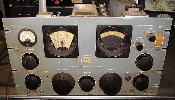
commercial users. Nowadays, many rebuilt SP-600 receivers have found new
homes in vintage AM ham stations around the world. Admired for its
massive proportions, ultra-smooth tuning, great sensitivity and sheer
dominance of the ham station landscape, SP-600 receivers are sought-after,
rebuilt, restored and then finally, once again, put to work. |
 |
|