|
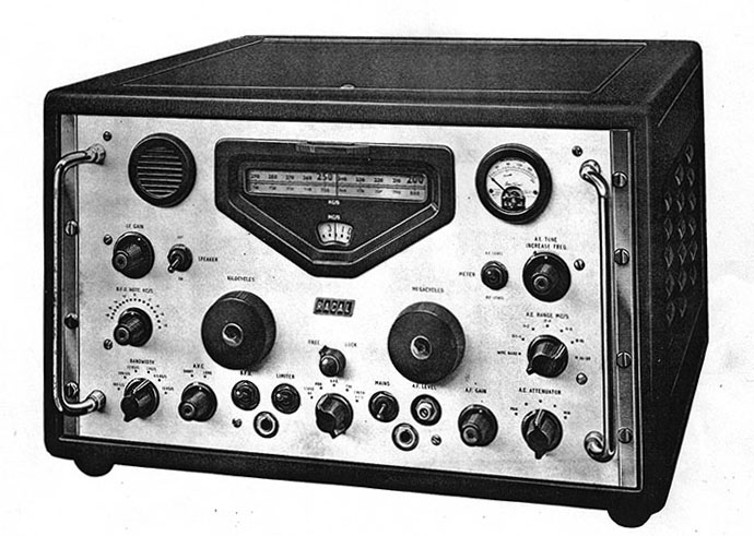
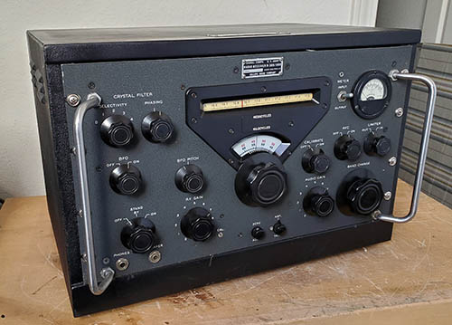
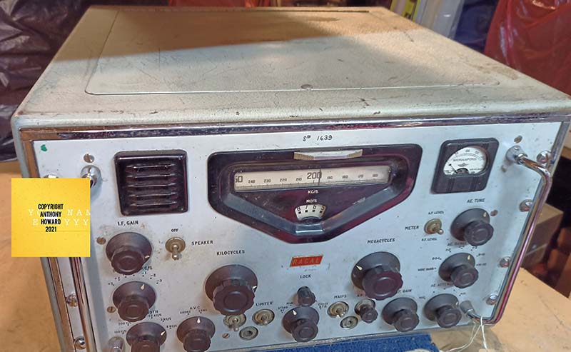
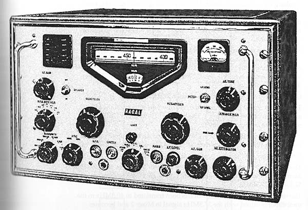
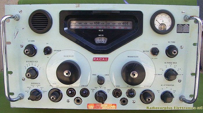
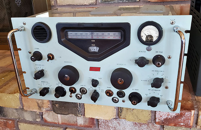
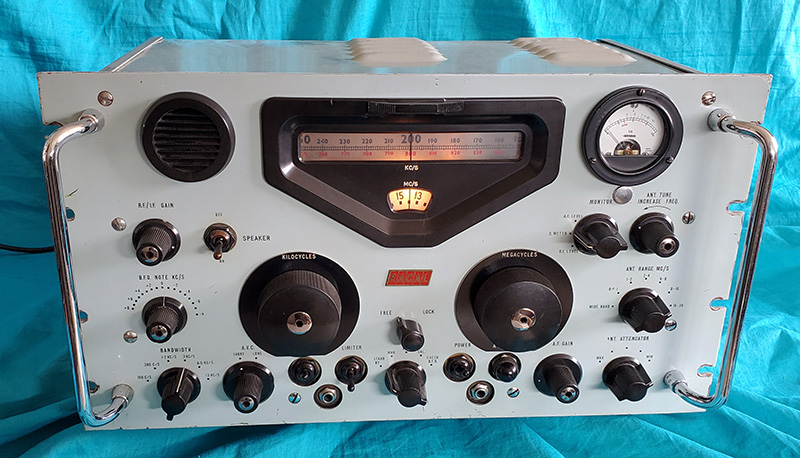
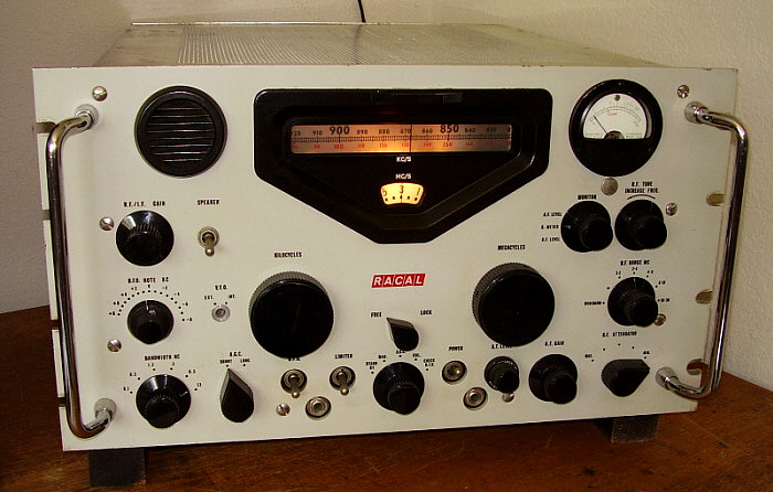
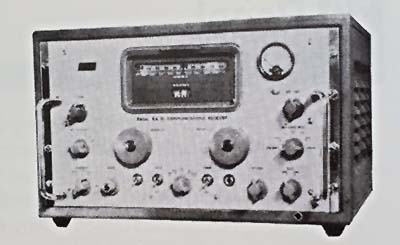
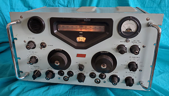
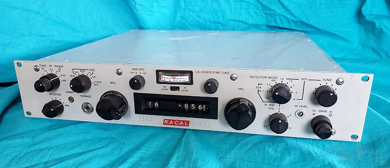
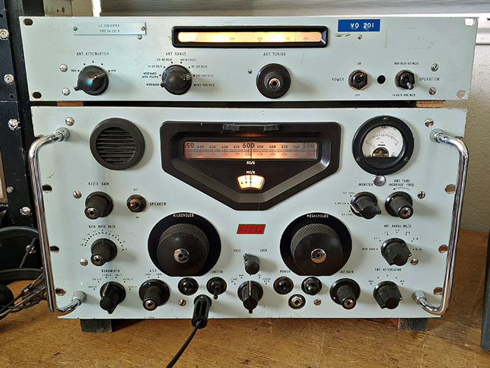
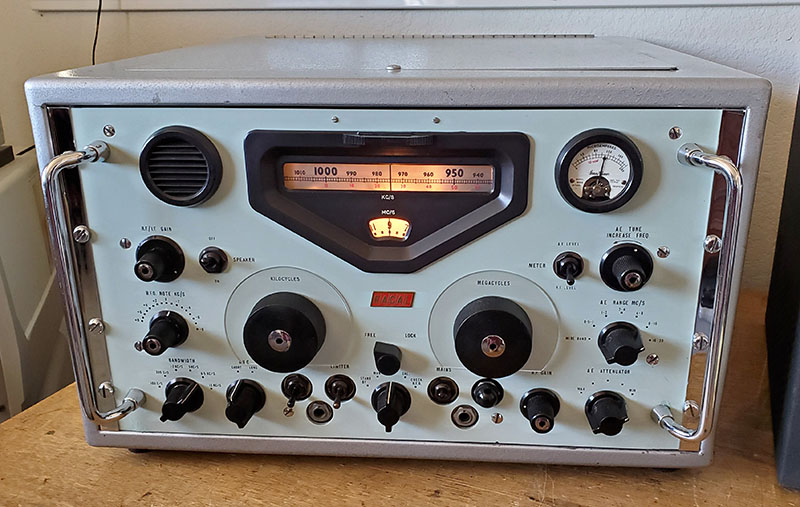
RA-17 Receiver
Alignment Overview
General
Info -
Alignments should follow the basic idea of the instructions in the manual.
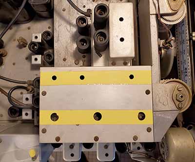
The 40mc BP filter and the 37.5mc BP filter have several
adjustments and the 40mc BP filter requires a spectrum
analyzer with tracking sweep generator (laboratory
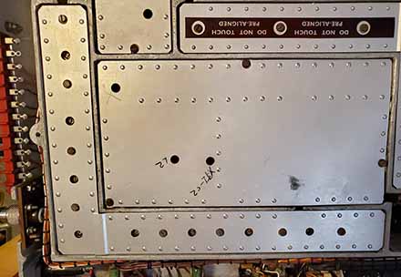
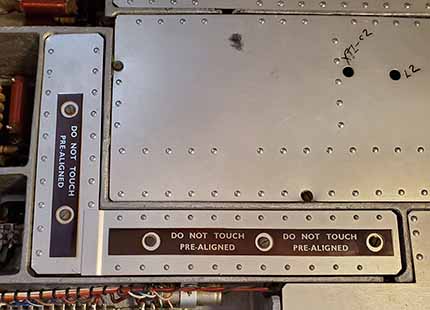
equipment) for accurate alignment. Originally, where there
were access holes to the 40.0mc BP filter adjustments, metal labels
were installed (glued) over the access holes that warned "Do
Not Touch - Prealigned." It's very common that
these 40.0mc BP metal labels will be found missing for obvious
reasons. Thoroughly read and reread the instructions before
"diving into" an alignment. You should thoroughly understand
how the RA-17 works before attempting an alignment.
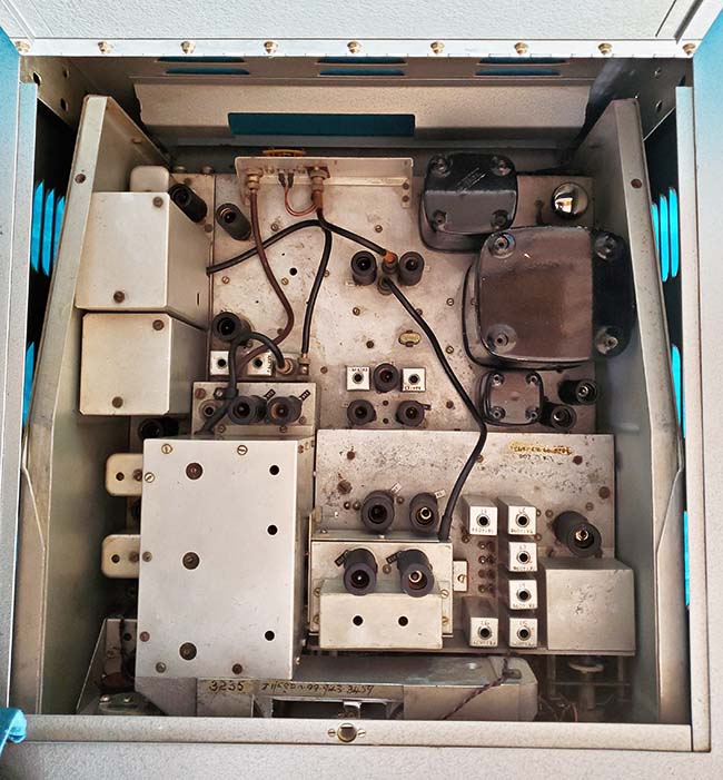
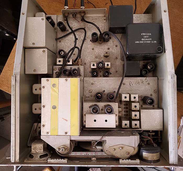
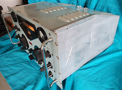
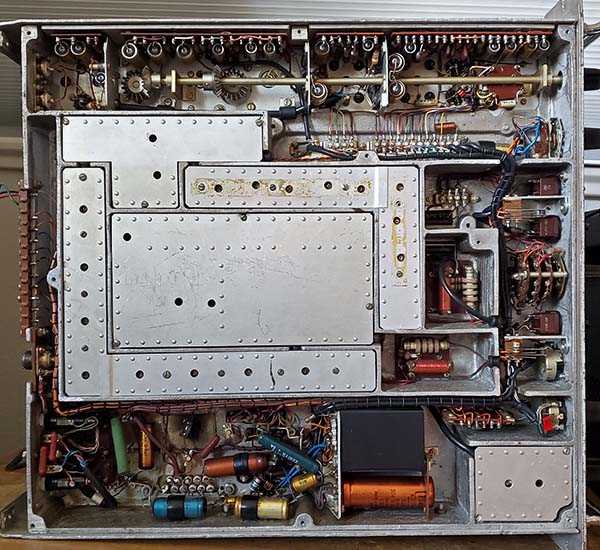
Adjustments are located almost everywhere,...top, bottom and
side of the chassis. Expect to have to move the receiver on
its side or rotate it around the bench for much of the
alignment. Probably placing the receiver on its right side
would provide access to all inputs and alignment adjustments with as
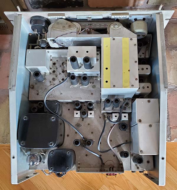
little moving as possible. Since a R-load needs to be
connected into the IF circuitry during alignment, the larger
bottom cover needs to be dismounted. The R-load is necessary
because during the alignment without the load the IF output
presents a "broad double-peak" and if adjusted to one of the
peaks would have the IF slightly misadjusted and trying to
find the exact center of the "dip" (the center between the
two peaks) is difficult. The 4.7K
eliminates the "double-peak" for an accurate adjustment.
Naturally, the top cover also needs to be off for the
alignment but all tubes and circuits are shielded even with
the top cover off. The left-side panel will have to be
dismounted for access to the 100kc LC filter and access
to C-136 (VFO-2 trimmer.) The manual's alignment procedure does
mention that the equipment used should be of
laboratory-quality and that a digital frequency counter will
be needed for accurately aligning the Crystal Filter.
Using a modern synthesizer-type RF signal generator would eliminate
the need for a separate DFC (for checking the
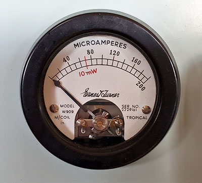
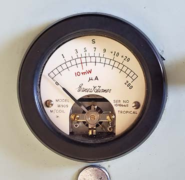
signal generator frequency.) The manual also indicates that
using the Carrier Level meter as an output indicator is
specified in most of the alignment measurements (using the uA scale set to 100 - half scale on the meter) but a VTVM can also be used depending
on what exactly is being measured (the output of the 37.5mc
BP filter requires a VTVM with RF probe.) Also, a heterodyne
frequency meter is specified for alignment of the
40.5mc to 69.5mc VFO 1 but, nowadays, one might think a
digital frequency counter could be used instead but there
are difficulties involved when trying to measure VHF sine
waves with regard to triggering points on the sine wave
causing frequency readout errors. A modern oscilloscope that
can sweep at 0.1u sec per division (10mHz per division)
would show slightly over 4 sine waves per division at 40.5mc and just under seven
sine waves per division at
69.5mc,...some modern 'scopes will also measure frequency in
a digital display somewhere on the screen. Even a modern VHF
receiver
with synthesized digital readout of the received frequency
could be used for the VFO 2 tracking alignment (the VHF
receiver must be able to receive AM signals.)
RACAL's Alignment
Procedure Caveats
- Be prepared,...the alignment procedure is fairly
complicated and it isn't exactly a "step-by-step" procedure. The writing is mildly convoluted making it
somewhat difficult to follow with a casual reading. First, don't be in a hurry to
complete the alignment. Read through the alignment procedure
several times as this will help you to understand what is trying
to be accomplished (this is assuming that this is going to
be the first RA-17 you've aligned.) Like many 60+ year old
instructions for electronic
devices that require periodic alignment, the RA-17 manual
was written at a time when most test equipment used vacuum
tube circuitry and analog dials. Consequently, many of the
steps described in the alignment procedure are due to the limitations of the test equipment of the time. The
heterodyne frequency meter for VFO 1 adjustment is a good
example of a type of test equipment that just isn't used
anymore
(although this might be an easy way to align the VFO
1.) The procedure has some expected measurements and
specifications added into the instructions that are helpful
but do lengthen the instructions quite a bit.
Extra stuff
needed,...a 4.7K resistor is required for loading the
first IF
transformer while it's being aligned. Also, a 1K resistor load is
required for the Ant Tune (Aerial Tune) adjustments and a
0.1uf coupling capacitor and a 12pf shunt capacitor are
specified (for Mk III versions.)
The 12pf shunt is for an external multimeter of a specific
type called out in the procedure. The shunt might not be
required depending on what equipment is actually used for
the measurement. I used a military HP VTVM (Type ME-26D) using a RF probe measuring
RMS and the shunt wasn't needed.
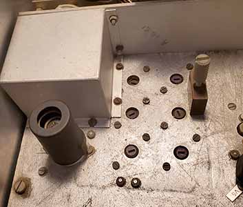
Weird stuff,...the 100kc LC filter has two
unconnected wires
inside the shield-box that must be soldered to terminals
inside the filter box. These wires connect the necessary
built-in damping resistors for alignment (the shield-box
must be remounted for alignment) and the wires are
disconnected after the 100kc LC filter alignment is
completed. The shield-box is on and off four times during
the alignment! And, unexpectedly, to be able to dismount the
100kc LC filter shield-box, the left side panel of the
receiver has to be dismounted! Two access slots are provided
on the left side panel but why they are present when the
side panel has to be removed is just one of those "weird"
things. The Crystal Filter can be aligned through a single access slot provided on the
left-side panel but dismounting the left-side panel has many
advantages during the alignment and it's highly recommended
that the left-side panel remain dismounted for the entire
alignment. The Crystal Filter alignment will require either
a digital frequency counter to set an analog signal
generator accurately (this method is actually mentioned in the later
RA-17C-12 manual) or using a modern synthesizer-type of RF
generator. Using a synthesizer makes setting up the Crystal
Filter very easy since the frequencies are just "punched in"
and the accuracy is unparalleled.
Pains and Oddities - To further complicate alignment, ALL of the adjustments are
referenced by using the
component ID, e.g., adjust L22 or C127, etc. and then
there's no "specifically for alignment" locator drawing
pointing out just where the particular adjustments are. You
have to use several of the component identifier
photos/drawings to locate the actual adjustment specified.
Even then not all of the identifiers are shown. For example,
the 4.7K R-load is referenced to the inductors of the IF
transformers but the actual connections to the IF
transformer terminals aren't mentioned and the terminals aren't identified on the schematic either. You have to trace
the wiring (on your first alignment anyway) to actually know which terminals
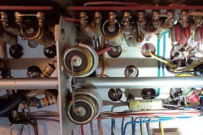
to connect the 4.7K R-load to. Another problem is C-195B
C-trimmer on the second IF transformer,...it's not even shown on
the Mark II schematic but it is present in many Mark II
receivers. Additionally, C-195B isn't shown on the component
identifying drawings. One has to just assume that the
unidentified C-trimmer on the second IF transformer must be
C-195B. While carefully doing the read-through of the procedure
(several times,) locate ALL of the adjustments and
mark them in pencil on the component photos/drawings and add
pencil notes to the procedure in the manual (again, assuming this
is your first RA-17 alignment.) That way you'll know
where all of the adjustments involved are located before you
start the alignment. This is just one of several tedious
pre-alignment steps
that are required on just about any complex
receiver on the "first" alignment. Some receivers will have
identifying markings on the adjustments on the chassis from
technicians that performed alignments in the past. They are helpful most of the time.
Since the receiver is
on its side for most of the alignment, clip leads can be
used for connections
under the chassis (ball-clips work best but alligator clips
also work.) For the 4.7K R-load needed, making up the resistor with wire
clip leads in advance will help (although it's only needed
twice.) Using tube extension sockets will make signal input
connections much easier. Most of the tools needed
are standard alignment tools. Non-conductive types might be
needed in the front end of the receiver. If
the receiver has been totally disassembled for a complete
rebuild, the manual's alignment procedure does provide
instructions for setting up the mechanical alignments necessary.
Other Complaints
- Due to the VHF conversion that has VFO 1 operating from
40.5mc to 69.5mc and the 40mc BP filter along with the
37.5mc BP filter, one might find that a lot of their vintage test
equipment just can't operate at those frequencies. Although I
found that my General Radio DFC worked great for measuring
the 1.000mc crystal oscillator, it was totally confusing to
use for measuring the output f of VFO 1 (just adjusting the
trigger would then result in a different frequency display.
This is due to the amplitude of the VFO 1 output changing as
the frequency changes and also there will be some harmonic
content in the output waveform that can also cause
triggering errors.)
The VTVM ME-26D worked fine for HF RMS measurements when
using its RF probe. For all signal frequency requirements below
20mc, the HP synthesizer worked great. For higher
frequencies I used the FNIRSI Oscilloscope with 50mhz
synthesizer RF signal generator combo and that worked fine.
What would be nice additions (for me) to the test gear for
aligning RA-17 receivers would be a good spectrum analyzer
with tracking sweep generator that can operate from LF up to
VHF,
a separate modern sweep generator that operates up to 100mc and
perhaps a VHF AM receiver with synthesizer digital frequency readout capable
of covering 30mc up to 150mc.
Alignment
Procedures Should be "Marked Up" - The RACAL manual's procedure doesn't "read" like
the typical U.S. Army Technical Manual (TM) instructions that
were written for Army radio technicians to easily follow in
a "step-by-step" method and
accomplish the alignment in a "quick and timely" manner. RACAL's alignment
instructions aren't as difficult to follow as, for example, the Hammarlund
SP-600VLF receiver's "impossible-to-implement" instructions but the RACAL instructions
definitely are not easy to casually read-through unless you
understand exactly how the receiver is designed to work. The
instructions are not written to
allow a "quick and easy" method of alignment
either. But, the more you read the procedure, the easier
understanding it becomes. Don't be in a hurry, re-read the
procedure several times and go ahead and make pencil notes
in the manual. It all helps
on the "first" alignment.
|
Using Modern Test Equipment |
Is it possible to go through the RACAL procedure and
eliminate the 60 year old test equipment references and
substitute modern test equipment? Modern test gear
will normally be easier to
adjust, much more accurate in the set up and give better
results for the alignment. Modern test gear, that can be
easily purchased today, is so far advanced and makes the
alignment tasks so much easier, using 60 year old test
equipment for alignments just doesn't make sense anymore.
The Internet has quite a few examples of "updated"
procedures with hints on using modern
equipment for aligning the RA-17. Some of these instructions are
selected portions of the complete procedure and most of
those are about the
40mc BP filter, the 37.5mc BP filter or tracking VFO 1 with suggestions on aligning
these difficult to adjust circuits. In fact, the RACAL manual's
procedure says that the 40mc BP filter shouldn't be tampered
with unless you have a spectrum analyzer with tracking sweep
generator
which, 60 years ago, nobody had (except for commercial outfits
and the military) since prices for that type of equipment
then were astronomical. Nowadays, good quality spectrum
analyzers with built-in tracking sweep generators are very
accurate, very small and not astronomically priced.
Inexpensive is a somewhat subjective term since spectrum
analyzers with tracking generators (SA+TG) are still somewhat expensive but
what is available today is probably 50X cheaper than similar
spectrum analyzer equipment that was used 60 years ago (and
probably several times more accurate.) There are
quite a few low priced DSA - Digital Signal Analyzer - devices
that would be very helpful in performing other parts of an
alignment. These
devices are made in China and are basically a two channel oscilloscope
with a built-in RF synthesizer signal generator. FNIRSI, a Chinese
company, makes a
tablet-sized, 2 channel 350Mhz oscilloscope with a 50Mhz RF synthesizer generator
and a passive spectrum analyzer, all of about $295
(the DPOS350P,...yes,
I have one and I use it a lot.)
However, the RF synthesizer generator in this particular device
unfortunately doesn't have a sweep function that works with
the spectrum analyzer so sync'ing becomes impossible. This
type of spectrum analyzer is referred to as FFT or Fast
Fournier Transform which
transforms the amplitude vs. time of the 'scope to amplitude
vs. a frequency spectrum. In other words, FFT only shows
basic signal position and strength over a wide frequency
range which is good for harmonic content types of
observations. If you have (or have access to) a SA+TG then
alignment of the 40mc BP Filter becomes possible (although
check performance first using the spectrum analyzer,
adjustment may not even be necessary.) If you
don't have the proper test equipment then don't attempt the
40mc BP filter adjustments. It's possible to check the 40mc
BP filter response with a signal generator but it's not a very accurate procedure
and certainly shouldn't be used for adjustment. The use
of a synthesized signal generator also makes the entire
alignment much easier. The required frequency and amplitude
are simply "punched in on the keypad" and the output accuracy is
unparalleled.
Modern Test Gear Caveat
- There is one very important caveat about using modern test gear
with vintage tube equipment,...most modern test gear wasn't
designed for the high voltages that might be encountered in
vacuum tube
circuits. This high voltage on inputs or outputs of the SA+TG could be the result of hook-up mistakes or just an
accidental momentary contact. In either case, instant and serious damage
could occur to the modern test equipment. Most SA+TG will
have a voltage limit of about 20vdc to 40vdc on the SA and
the TG will be much less than that. Even if the test gear is
capacitively-coupled, that isn't an assurance that damage
won't happen since the capacitor will pass the initial
contact voltage for an instant (as a strong voltage pulse.) Most of the time a 10:1 or 100:1
probe can be used, but not always. Fixed-value inline
attenuators can also be used, sometimes. Another problem is impedance
matching,...most SA+TG are designed for RF transmission line
applications and will have a 50Z input impedance. Many of
the input circuits in a vacuum tube receiver will be much higher Z
and could be "loaded down" when connected to the SA+TG.
Depending on what is being observed in the receiver, whether
voltage levels are accurately shown on the display might be
irrelevant since only the waveform shape is important.
These types of hook-up problems can be corrected, sometimes quite easily, but
always some sort of protection of the inputs and
outputs of the modern test gear is required when interfacing
with vintage tube equipment. The most common solution is to
use an attenuator with a buffer stage. This will provide
good isolation and can even provide impedance matching.
The upshot is when interfacing a modern test instrument with
a vintage tube receiver be very careful and think about what
you're trying to accomplish. Know what the voltages are in
the circuit before connecting the test gear and know what
the RMS voltage levels of signals that are going to be encountered.
Also, remember what the input limitations are for your
modern test gear.
Be aware that sometimes AC line bypass capacitors can "leak"
AC voltage to the chassis if it isn't grounded. This can end
up with AC voltage being connected to the negative input on
"floating inputs." Grounding all test gear and the receiver
chassis is required. Most three-wire AC plugs do ground the
receiver chassis. Of course, AC-DC devices should always be
powered through an isolation transformer and usually the
chassis and B- are separate so always check voltages levels
before connecting any modern test gear.
When the
RA-17 was built, RACAL had test jigs with oscilloscope displays
and built-in sweep generators with markers that were mostly
vacuum tube based equipment. Even at RACAL, using this
special equipment for adjusting the
filters was still a fairly time-consuming process.
Modern test equipment is probably ten times more
accurate and fifty times cheaper than what RACAL used 60+ years ago. If you can
afford it, modern test
equipment will ease all of the adjustments quite a bit
provided you know
how the RA-17 is supposed to work and you know how to use the
modern test equipment including protecting its input and
output connections. Check
www.radiomuseum.co.uk
as Allan has multiple pages about working on various types
of problems involving the RA-17 and
details on aligning the RA-17 BP filters and VFO 1 with modern
equipment. Lots of photos
too. Summary
- Like any complex receiver, the
"first one" worked on is
your "learning experience," any that follow become more
familiar and are almost always much easier to
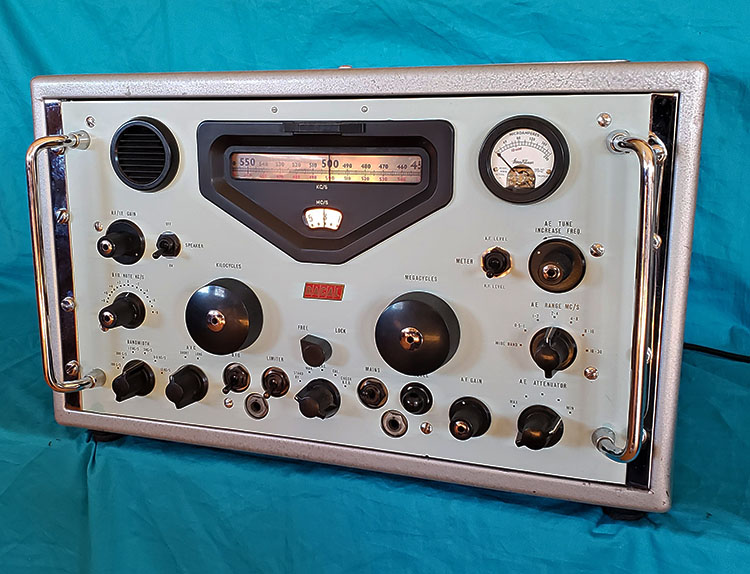
get through. If you've successfully reworked R-390A or 51J
receivers, then you'll sort of know what to expect in a RA-17 or RA-117
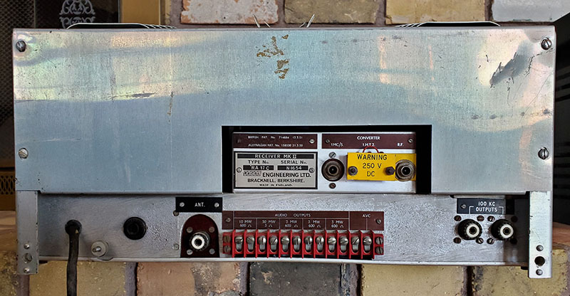
receiver. UPDATE NOTE:
Most of what is written above is based on the RACAL manuals
for the RA-17 Mark II and the RA-17L and the RA-17C-12, both Mark III receivers. I've found a
British Military
Technical Handbook for Field and Base Repairs for the RA-17
Mark II and for the RA-17L Mark III (hereafter
referred to the Handbook.) Since this handbook was
written for technicians (I think) it seems to be very direct
in describing each of the steps necessary for alignment
which helps to clarify the tasks. It's basically the same
information that's in the RACAL manuals but presented in a
somewhat easier-to-follow format. However, there are
absolutely no component location drawings provided so the
user has to have component location drawings/photos from
another source (the RACAL manual, probably.) The Tech
Handbook is from 1967. I found this manual/handbook on the
Internet while searching for alternate manuals for the RA-17 Mark II receiver (free download
from VMARSmanuals.co.uk.) As mentioned, the handbook covers
both the Mark II version and the L Mark III version. This
Handbook should be used along with the RACAL manual - it
can't be used exclusively because of the lack of component
location information. |