Radio Boulevard
Western Historic Radio Museum
 

Shipboard Radio Receiving Equipment
1918 up to 1925

(formerly
"The Classic Shipboard Wireless Receivers - SE-1420, IP-501 & IP-501-A")
 

1. Navy Department - Bureau of Steam Engineering - SE-143 - National Electrical Supply Co.
2. Navy Department - Bureau of Engineering - SE-1387 - National Electrical Supply Co. (NESCO)
3. Navy Department - Bureau of Engineering - SE-1834 - National Electrical Supply Co. (NESCO)
4. Navy Department - Bureau of Engineering - SE-1420 - Wireless Specialty Apparatus Co. (WSA)
5. Matson Line S.S. Mariposa - IP-501-A (Commercial) - Wireless Specialty Apparatus Co. (WSA)
 

Histories, Circuit Designs, Operation and Performance Testing

Restorations of SE-143, SE-1387, SE-1834, SE-1420 and IP-501-A

Operating 100 year old LF-MW Radio Equipment in
Today's Polluted Electro-Magnetic Environment

by: Henry Rogers - Radio Boulevard-WHRM


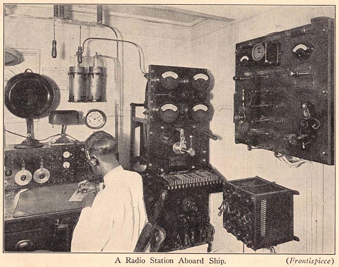
Navy Shipboard Radio Room  ca. 1925

According to RCA, the 1918 SE-143 was the first radio receiver available that performed adequately and was able to receive all types of signals whether they were from Spark Transmitters, Arc Transmitter, Alexanderson Alternators or from Vacuum Tube CW Oscillators. Surprisingly, RCA supplied manuals for the SE-143 as late as 1936. But, how could a WWI RF Tuner be in use onboard ships years after it should have been obsolete? UPGRADES! The SE-1387 and the impressive SE-1834 were especially designed, in 1922, to be used with the SE-143 (and similar receivers) to upgrade this WWI RF Tuner into a seven-tube TRF receiver with three RF amplifiers, a detector, a tunable heterodyne oscillator for CW and two stages of audio amplification. All accomplished externally with no modifications necessary other than wire-connecting these two devices to the already existing SE-143 terminals. After WWI ended, the radio receiver designs only got better with the SE-1420 Receiver that was introduced in 1919 and continued to be built as late as 1927. The SE-1420 paved the way for the incredible IP-501-A receiver that was used onboard ships and at coastal stations into the late-thirties with manuals available from RCA as late as 1938. The following examples of WWI and 1920s electro-technology illustrate how incredibly fast radio circuit designs and vacuum tube evolution were improving the communications equipment being built for commercial and military use.


Navy S.E.143 - U.S. Navy - Bureau of Steam Engineering
National Electrical Supply Company (NESCO)
SN:848N  Date on ID Plate - 1918

U.S. Navy - Bureau of Steam Engineering

S.E.143 - Short Wave Receiver - SN:848N - NESCO - 1918 Contract


The S.E.143
was a WWI Receiver that was essentially an RF Tuner (hereafter referred to as SE-143) It was used extensively by the Navy in the post-WWI era from 1918 up into the late-1920s (manuals for the SE-143 were available from RCA as late as 1936.) Other versions, like the IP-500 (usually built by Wireless Specialty Apparatus Co.,) were used on commercially-owned ships. The SE-143 was a sophisticated RF Tuner that provided a series LC Primary tuner and a parallel LC Secondary tuner. The Coupling coil between the Primary LC and the Secondary LC could be varied 90º and actually moved the coil from the control using bell-crank levers. An adjustable position Tickler coil (for VT detectors) was located inside the secondary coil form directly under a series-connected Secondary Coil extension to promote better feedback. The front panel TICKLER COUPLER control used a bell-crank lever control to rotate the Tickler coil 90º for regenerative feedback. There is also a large untuned additional Secondary coil mounted next to the main Secondary coil. The untuned secondary coil was to provide a broad response for tuning with external Crystal detectors or for finding stations transmitting on an unknown wavelength when using a VT detector. When searching for unknown stations, the Coupling was set to MAX for the strongest signal albeit not a very selective response. Once the station was found, then the SE-143 could be switched back to "TUNED" allowing the receiver to be further adjusted for the maximum signal level and best selectivity. Additionally, as the wavelength is decreased (higher frequencies,) the unneeded secondary coil sections are switched out (indicated on the schematic at 48-49 and 41-42.) The Primary Inductance also has switches to disconnect unneeded sections as the wavelength is changed (indicated on the schematic at 26-27 and 17-18.) The tuning range is 250M to 6400M or 1200kc down to 47.0kc. To allow the SE-143 to tune to VLF a Secondary Loading Coil, a Primary Loading Coil and a Tickler Loading Coil could be connected using the front panel terminals so marked. 


The SE-143 didn't have an onboard detector or an onboard audio amplifier,...it was an RF tuner only. The VT detector was originally provided by the Audion Control Box that was designated as the SE-1071. It provided just one tube that operated as a regenerative detector for the SE-143. There was a two-stage audio amplifier available, the SE-1000 that could also be added. If the SE-143 was operated with an external regenerative detector tube, the SE-143 internally provided the "Tickler" coil (an untuned, adjustable rotational-position coil located inside the Secondary coil) connection since the regeneration function had to provide an in-phase EM field in close proximity to the secondary coil for sufficient feedback. The crystal detector function was mainly provided for emergency situations and its inclusion into the design was a stipulation of Navy regulations.

What the Specific Controls Do - The Primary Condenser dial has a 180º scale for half of the dial and linear scales for notations on the other half. The Secondary Condenser is calibrated in wavelength and also has the "letter designations" that were used during WWI and somewhat after as specifying important wavelengths (or frequencies.) Wavelength scaling is the figure shown times 100. A logging scale is also included in the other half of the dial. The inductance switches have letter designations on the Primary LC and numbers on the Secondary LC. The scales for the TICKLER COUPLER and the INDUCTIVE COUPLER are 0 to 180 with a MIN and MAX indication at each end. The scales imply the degrees of rotation for the specific coil. The BUZZER was used as a "potent" signal generator to be used when trying to find a sensitive spot on a crystal detector. The typical battery voltage for the BUZZER is no more than 2vdc if the buzzer is in good condition and adjusted correctly. There's spark gap between the ANT and GND terminals to provide a method to dissipate static charges on the antenna (common problem at sea or in windy areas.) Two sets of terminals are for LW loading coils that, when connected, allow the SE-143 to tune lower than it's 6400 meters (47kc) lower tuning limit. Various types of loading coils could be used (see vintage shipboard photo further down showing a DeForest Duo-lateral LW coil apparatus being used for VLF frequencies.) The DETECTOR terminals are provided for connecting the Crystal Detector. The eight vertically aligned terminals allow mating the SE-143 to the SE-1071 Audion Control Box. However, it's not specifically necessary to use the SE-1071. The terminals provide connections to the TICKLER COIL, AUD TEL, TELEPHONES (for Crystal Detector) and the receiver secondary LC outputs RA (grid-amplifier) and RE (ground-earth.) The SECONDARY SWITCH allows selecting TUNED or UNTUNED with the latter routing the SECONDARY  LC to an untuned coil that's closely coupled to the secondary inductance for a broad frequency response for easier tuning when using a Crystal Detector (it can also be used with an Audion detector when searching for unknown stations.) The DETECTOR SWITCH routes the secondary LC as necessary for either Crystal Detector or for an Audion detector.


from George Sterling's "The Radio Manual" 1st Edition - 1928


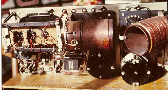
SE-143 Inside - RF Tuner only. Signal detection and amplification was an external function.


Close-up of the Secondary Inductors. Foremost is the Primary to Secondary Coupling Coil that can rotate 90º. Then the fixed-position, Untuned Inductor for Xtal set-ups or finding unknown stations (Coupling Coil must be set to Maximum coupling for strongest signal response.) Inside the Main Secondary Inductor the Tickler Coil can be seen. The Tickler Coil rotates 90º to provide adjustable regeneration with an external VT detector. Note that there is a series secondary coil directly over the Tickler coil to provide a sufficient EM feedback path for regeneration to occur.


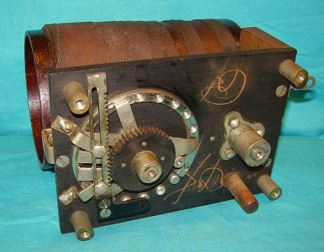
Close-up showing the Bell Crank levers for adjusting the Inductor Coupling and the Tickler Coil Coupling. Also, the knife-switches for "Tuned-Untuned" and "Detector Switch" functions.

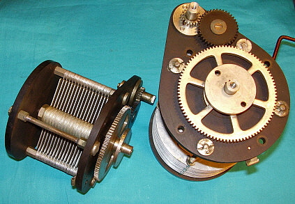
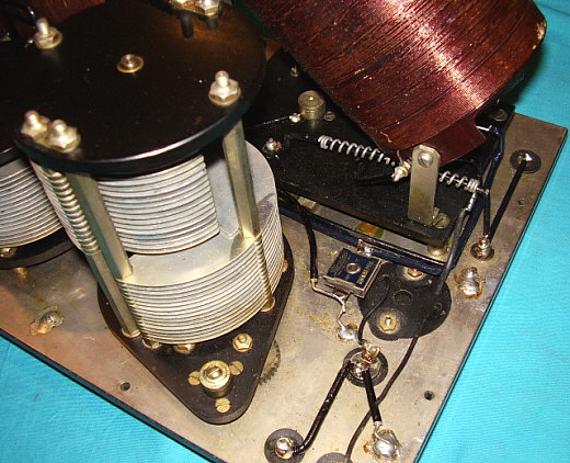
Refurbishing the SE-143 - This receiver had been stored poorly, probably for decades. The back of the cabinet had been missing at some time in the past and that allowed some type of pest to take up residence in the Secondary Coil. Luckily, it wasn't a mouse family since none of the wiring was eaten or even nibbled on. Lots of dried-up debris like leaves and what looked like dog hair. It all cleaned up easily using Glass Plus and Isopropyl Alcohol. Cleaning the Primary and Secondary condensers took a lot of time using various brushes and lots of Glass Plus. After several "flushes" using Glass Plus, the rotor plates and the stator plates were further cleaned by sliding a folded piece of heavy paper through the spaces to remove any other debris. Although this process was rather time-consuming, it resulted in the air-variable condensers looking excellent and working as they should. The inductor windings looked in good condition but the two bell crank lever controls were very stiff and hard to move. The same "stiffness" was found in all of the controls. Careful cleaning followed by lubrication using very small amounts of WD-40 loosened up all of the controls. I also used DeOxit on the knife-switches and on the contact switches. Since there aren't any active components in the SE-143, all that's required is that the inductors and variable condensers are in good condition and that the contact switches are also working correctly. Essentially, the circuitry is almost all mechanical and this requires that all contacts are clean and all wiring is present. What is astounding is that this 100+ year old radio apparatus is complete and all original. It has never even had any soldering work performed on it and, other than the indications of less-than-perfect storage, it's pretty much as it was built by NESCO back in 1918,..amazing.


S.E.143 data plate - Note the 3000M error. This should have been stamped 6400M. I've confirmed that SN:848N does tune to the 6400 meter wavelength.

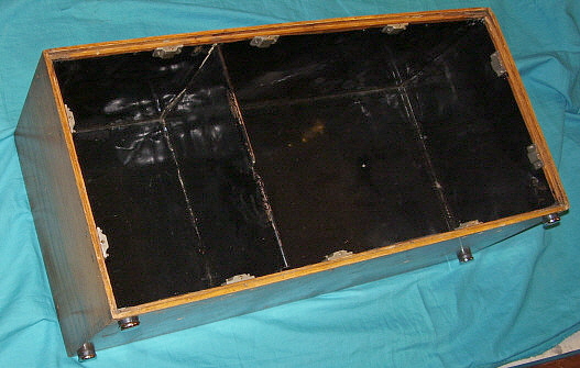
Cabinet Work - The SE-143 cabinet is made out of mahogany stained a dark reddish-brown color. The interior has no metal shielding installed. The right side front of the cabinet has two broken pieces of wood that are the full length of the height of the side piece. I had to remove the two latch-bails to be able to glue these pieces back correctly. The bottom front section is split and broken requiring gluing and clamping. I use Franklin's Genuine Hide Glue for this type of repair. This Hide Glue is not the old type (rendered from horse hoofs and hides) that needed to be a smelly, hot liquid that was quickly painted on and set-up as soon as it cooled. Franklin's is synthetic hide glue with all of the good properties and minus the disadvantages. This glue is amber colored and transparent so it looks old if it happens to show in the joint. It does take a fairly long time to set-up but the glued joint has to be clamped and let set for about an hour. For full strength the glue joint must dry overnight. Unfortunately, with these types of breaks, I have to use a combination of hand clamps and pipe clamps because of the distance between the glue joint and the back of the cabinet and because of the angle of the breaks. The need for pipe clamps is common with most cabinet repairs involving glued joints. The complete gluing took about a day to accomplish and used three pipe clamps and about half a dozen hand clamps.

I do have the rare front cover for this SE-143. It has had some crude repairs done to it. The cover piece of wood was replaced with 1/2" plywood, apparently many years ago. It's stained to a color that's sort of close and has a vintage-look to it. Also, one of the side pieces was replaced and the dove-tail joints not reproduced. Instead, the "dove-tails" were cut off and the wood nailed in place. It's pretty crude. Overall, the condition is probably a little worse than average BUT, at least, I do have the top cover, which is rare to find with an SE-143 receiver. 

The back of the cabinet ended up missing sometime in the past. Someone cut some 1/4" birch plywood, glued two pieces in a sandwich to create a 1/2" thick, stepped-type of back that fits okay. It wasn't stained and finished however, just left bare wood. Luckily, it's mounted with only four screws, so it can be easily removed for rework and staining. I have lots of red mahogany stain but I think I'll have to mix some golden oak in to get the correct color. I'll also work on getting a better fit, touching up the edges so they don't look like plywood and then stain to match. For the time period and that fact that most of the SE-143 receivers were expected to be "at sea" I'd expect varnish was the original finish used. However, after 100 years, there's not too much original finish left now.  NOTE: Close examination of the SE-143 cabinet with this make-shift cover removed seems to indicate that perhaps there never was a rear cover. I can't find any residue of glue, there are no nail or screw holes. I can't imagine that there wasn't a back to the cabinet,...I just can't find any evidence that shows how one would have been installed. However, since this make-shift cover fits and after staining it matches fairly well, I'm going to install it. If I find out later that SE-143 cabinets didn't have back covers, it can easily be removed.

Testing the SE-143 - Preliminary Test - Since the SE-143 is an RF Tuner, a different type of testing must be performed to determine if it was going to be operational. I used the HP-606B RF Signal Generator and the FNIRSI DPOS350P "tablet-type" oscilloscope. I connected the 'scope to the RA and RE terminals (the Secondary LC - tuner output) and connected the signal generator to the ANT and GND terminals. I first set the sig-gen to 600 meters or 500kc with no modulation. The oscilloscope showed a sine wave at the RA/RE terminals. A little bit of adjusting and the signal was easily peaked for maximum sine wave showing on the 'scope. I tried various frequency inputs ranging from 800kc down to 60kc and I was able to peak the signal on all ranges. This indicated that the RF Tuner did function as far as being able to adjust resonance in both the Primary and Secondary tuners. I performed the same tests using a 400hz modulated signal, not that I expected different results but just out of curiosity to see what a modulated waveform looked like.

Crystal Detector Test - The next test was to connect a crystal diode (1N34 germanium diode) to the CRYSTAL terminals (it doesn't matter for the cathode or anode connections.) I connected a set of Baldwin Type-C 'phones to the TELEPHONE terminals. I placed the DETECTOR SWITCH in the CRYSTAL position. I had the SE-143 tuned to 1000 meters or 300kc and the HP-606 was also tuned to 300kc modulated at 400hz. The signal came over the 'phones quite well. It did require a little bit of peaking of both the Primary and Secondary tuners for a maximum response. I tried a few other frequencies and was able to tune them in quite well.

Signals "Over the Air" Test - Next was to try an actual "over the air" signal. About the strongest MW signal around here is from KKOH on 780kc or about 385 meters. I used the HP-606 to pre-tune the SE-143 for 780kc. I connected one leg of the Collinear Array for the antenna (about 300 ft end-fed wire) and used the house ground. KKOH 780kc was easily audible and, with a little peaking, it was coming in strong using the 1N34 crystal detector. I tuned in a couple more BC stations, KPLY on 630kc and KOLO on 920kc. With the COUPLING on 110, I had enough selectivity to separate these stations easily and still maintain a good signal level. I tuned to "S" which is the WWI letter designation for 100kc (3000 meters.) This is the transmitting frequency of the LORAN-E Master Station "M" located in Fallon, Nevada about 50 miles east of my QTH. "M" runs 400KW to a 625' tall ground isolated vertical with a 900' C-hat,...it's a formidable LF signal here in Dayton Valley. "M" was easily tuned in and peaked with the Secondary Condenser exactly on "S."


Showing the output at RA/RE (Secondary LC) - 500kc sine wave input on ANT input from HP-606B with no modulation. The FNIRSI DPOS350P shows 500.3khz on the DFC and shows the output is 1.82VP/P. This preliminary test showed that a signal could make it from the Antenna to the "Tuned Output."

VT detector and Regeneration Test - The SE-143 was normally used as an RF Tuner ahead of a Vacuum Tube detector. Using a Crystal Detector was generally only for emergencies where no power was available to operate the tube or tubes. The SE-1071 was the Audion Control Box and it interconnected with the eight vertically aligned terminals on the right side of the receiver.

The Hook-up - To operate the SE-143 with a VT requires a vintage triode tube and tube socket, an adjustable filament voltage source and another adjustable voltage source to provide plate voltage. A couple of things to observe are RE is connected to F- and B- is connected to F+. The 'phones are connected to the AUD TEL terminals. The plate voltage B+ is also connected the lower AUD TEL terminals that has one lead of the 'phones. The top AUD TEL terminal has the other lead of the 'phones but also has a jumper to connect the upper AUD TEL terminal to the lower TICKLER terminal (the use of the AUD TEL terminals was later found to be unnecessary.) Then the upper TICKLER terminal is connected to the Plate terminal on the tube socket. The jumper has to be externally installed because this connection was actually made inside the SE-1071. Additionally, the connections to 'phones, Tickler Coil and VT plate were all internal to the SE-1071 and controlled by a switch that selected OSCILLATOR (Regen going through the Tickler coil) or DETECTOR (Tickler coil shorted for a non-regenerative detector.)

The Ship's Generator as a B+ Source - Interestingly, the SE-1071 could provide B+ plate voltage either from storage batteries or it could be provided by the ship's +125vdc generator. There was an adjustable potentiometer to adjust the plate voltage but the +125vdc ship's generator only has a couple of filter chokes inline inside the SE-1071, so one has to wonder exactly what the plate voltage was and what the value of the variable resistance was (neither are indicated anywhere on the SE-1071 schematic.) There's a switch and terminals provided for selecting either storage batteries or the ship's generator as a B+ voltage source.

Vacuum Tubes Available in 1918 - Another consideration is the actual type of vacuum tube used in the SE-1071. In 1918, a Moorhead Electron Relay tube might have been used or perhaps a Western Electric VT-1. The UV-200 and UV-201 weren't introduced until around mid-1921, along with most of the other consumer-broadcast radio vacuum tubes, so they wouldn't have been used until that time. The WE-215A tube might have been available in 1919, but the special socket required for that tube seems to eliminate it for use in the SE-1071. The most likely VT used in 1918 would have been the WE VT-1 or the Electron Relay (there were several manufacturers for the ER type of VT during WWI.) For initial testing of VT detector and regeneration, I'm going to use the UV-200 and see how that works even though it couldn't have been used in 1918.

What Doesn't Work - My first attempt with the UV-200 had clip-leads, improvised very long lead connections other places and didn't follow what the SE-1071 schematic indicated. As expected, while this lash-up worked fine as a non-regenerative detector, I couldn't get the Detector to break into oscillation. I tried using a UX-201A and a Type-30 with the same results. I tried plate voltages from a low +15vdc up to +70vdc and could never get any of the Detector tubes to oscillate.

What Does Work - Finally, I decided to follow the SE-1071 schematic and hook-up closely. I used very short wire connections. I connected the 'phones one lead of the phones to the lower TICKLER terminal and the other 'phone lead to +45vdc. The upper TICKLER terminal was connected to the detector tube plate. Connecting to AUD TEL isn't necessary. I had connected the RE terminal to F+/B- but the SE-1071 has RE going to F- so that connection was changed. I replaced the 250pf grid blocking cap with a 500pf. I changed the grid-leak resistor from 1.2meg ohm to 680K (600K on the SE-1071 schematic.) I connected the grid-leak to B- as indicated on the SE-1071 schematic rather than in parallel with the grid blocking cap. I installed a 0.004uf capacitor from the junction of the 'phones and the Tickler coil as indicated on the SE-1071 schematic (although the value isn't shown on the SE-1071 schematic.)

Following the SE-1071 schematic and the hook-up exactly as shown resulted in tremendous regeneration capabilities with being able to easily adjust the TICKLER COUPLER for detector oscillations.

In actually operating the SE-143 and testing various wavelengths of reception, I've discovered that the detector plate voltage must be adjustable, as the SE-1071 B+ voltage was. The B+ supply must be capable of adjustment from about +20vdc up to about +90vdc. I've found that when operating the receiver at the higher frequencies, e.g., 400kc up to 1000kc, about +25vdc to +45vdc provides enough detector plate voltage for good regeneration and oscillating capability. The lower in frequency the SE-143 is tuned, the higher the detector plate voltage has to be adjusted to in order to maintain the capability of using the "untuned" TICKLER coil to get the detector to oscillate. At 100kc, I had to increase the detector plate voltage to about +70vdc for oscillation to occur. But, with +70vdc on the detector plate, I couldn't induce oscillation at 60kc,...that's just 40kc lower in frequency. The conclusion is that the SE-1071 Plate Voltage adjustment potentiometer allowed the user to adjust the detector plate voltage based on how easy it was to induce oscillations using the TICKLER adjustment. At 1000kc, only about +20vdc detector plate voltage will allow easy regeneration and oscillation. However, one also has to consider that all of the vintage photographs show the SE-143 and SE-1071 being set-up with some type of low frequency loading coils. The additional inductance on the Primary LC, the Secondary LC and the Tickler L would certainly help with regeneration when tuning below 100kc.

LW Loading Coils - When the tuned frequency was lower than 100kc, it certainly helped to have additional inductance in the Primary, Secondary and Tickler coils. Without additional inductance, the receiver won't go into oscillation. Also, the Primary tuning becomes ineffective, although the antenna used is also a factor at lower frequencies. Both vintage photos (below) showing SE-143 stations show that LF Loading coils were in place. The NAA Station used massive inductances with tapped switches. The USN Shipboard station used a DeForest Duo-lateral Tuner with LF plug-in coils. It's obvious from actually using the SE-143 and from examining vintage photos that LW Loading Coils were necessary for dependable operation below 100kc. Adjustable plate voltage and filament voltage is required for reliable oscillation from 100kc up to 1200kc.

Adding a Single Stage of Audio Amplification - I have a Pilot Radio Redi-Blox Single Stage Audio Amplifier from about 1930 that I use with the SE-1420 receiver to boost the output of the detector tube for that receiver. It provides enough audio level to actually hear very weak signals, like NDBs, using headphones. I've also used this audio amplifier with the Spherical Audion Receiver with good results.

To hook-up the single-stage AF amp, the primary winding of the input transformer is connected to the two points where the headphones were connected,...to the AUD TEL terminals directly and with the B+ connection to the lower AUD TEL terminal and the one end of the jumper to the TICKLER COIL on the upper AUD TEL terminal. I use a UX-201A tube as the amplifier so about +4.5vdc connects to the filaments and I usually use about +60vdc on the plate and that is routed through the 'phones before going directly to the plate terminal. The F+ and the B- are connected to the B- terminal of the A-B power supply (B- is connected to F+.) Audio Output can be controlled by the tube filament voltage but normally I use the SE-143 Inductive Coupler or the Tickler Coupler to control sensitivity. A 1920s Horn Speaker could be used on just about any of the AM-BC stations. Hearing NDBs (the few left, anyway) will require 'phones. The NDBs are MCW signals but having the detector oscillating will make finding the NDB's carrier easy. Just tune for zero-beat and the MCW tone will be easy to copy. 


Regenerative Detector Set-up with UX-201A Detector Tube. Wire leads are as short as possible and clip-leads kept to a minimum. The A-B-C Power Supply is homebrew solid-state that I built about 45 years ago,...still works.

The SE-143 "aged" quickly and, by 1920, other more advanced designs were being developed and introduced into the Navy. Possibly, the need for specific types of detector tubes became a problem as vacuum tubes evolved. However, the SE-143 was still an excellent RF Tuner so newly designed "add-on" units were introduced around 1922. These add-ons enhanced the performance capabilities of the SE-143 allowing the Navy to continue using it, in combination with some of the external devices, to modernize the performance and that allowed the SE-143 to continue on as a shipboard tuner-receiver for several more years.

NOTE 1: The U.S. Navy created the Bureau of Steam Engineering in the 1860s as a technical engineering department, initially to help with the transition from sailing ships to steam powered ships. Later, new technologies like electrical and wireless engineering were added. In 1920, the name was changed to Bureau of Engineering and, in 1940, it was renamed Bureau of Ships.

NOTE 2: Interestingly, the data plate on SE-143 SN:848N has the wavelength "punch-stamped" as 250M(1200kc) to 3000M(100kc) rather than the standard 250M(1200kc) to 6400M(47kc.) 6400M was the standard longest wavelength tuned on the SE-143 and 6400 meters is what is shown as the lowest wavelength on the Secondary Condenser dial. I've confirmed that SN:848N does tune down to 6400M, so, for some reason, the data plate was stamped erroneously at "3000M." See photograph above near the beginning of this SE-143 section.

NOTE 3: The "Short Wave" designation is relative to the time period and to the typical frequencies that the Navy used during WWI. A more modern designation would be that the SE-143 is an LF/MW RF Tuner-Receiver (Low Frequency or LF is from 30kc to 300kc and Medium Wave or MW is from 300kc to 3000kc.)

SE-1387 - R.F. Driver (Tuned Heterodyne Oscillator)
  SE-1834 - Amplifier, Radio-Audio 125-30,000 Meters, Audio Universal
(3-stage Broadband RF amplifier, Detector, 2-stage AF amplifier)

Navy Department - Bureau of Engineering - National Electrical Supply Company (NESCO) - 1922 Contract
 

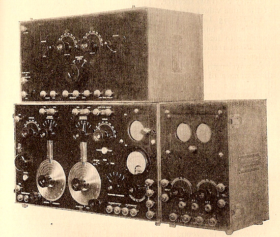
Post-WWI Radio Improvements - As radio evolved post-WWI, the need for new radio equipment was offset by the reduced post-war Navy budget that limited extravagant purchases to a certain extent. This resulted in the newest and largest Navy ships being prioritized for the newest equipment while an older or smaller ship would have to utilize older, maybe even WWI-era, radio gear. Improvements were much easier to fit into the budget and, as radio evolved, these external circuit additions allowed older radio equipment to be updated to provide usable service. Most peripheral equipment came in the form of RF amplifiers to be used ahead of a regenerative detector provided stronger signals and antenna isolation. Audio amplifiers to provide stronger post-detection signals to drive multiple outputs. Devices for interfacing specialized antennas such as loop antennas for direction finding. By 1922, there were several types of "add-on" devices available to improve the performance and usability of older receivers. This SE-1387/SE-1834 combination (shown to the right) was specifically for the SE-143, IP-500, SE-1220 or other similar RF Tuners.

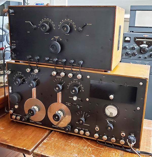
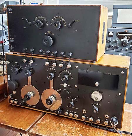
Although the SE-1387/SE-1834 combination appears to be a receiver, it's far from being a "complete" receiver. The SE-1387 is actually a "tuned" Heterodyne Oscillator and the SE-1834 is almost a complete receiver but it's minus any selective RF tuning capability. Both units have to be used with RF Tuner sets like the SE-143. Unlike the earlier shipboard radio equipment that were housed in wooden cases, perhaps lined with metal shielding, the SE-1387/SE-1834 combo was built with an aluminum front panels and housed in an aluminum case. Both units are installed into individually shielded compartments to prevent any stray coupling between the units. The size of the metal cabinet matches the height of the SE-1420 so it's somewhat smaller than the enormous cabinet of the SE-143. Most Navy installations would place the "add-on" units on top of the SE-143 and wires interconnecting the units were routed around the panels to access the needed terminals. Although this particular example has the SE-1387 and the SE-1834 housed into a single cabinet, most vintage photographs show individual "add-on" units were single-function devices that were housed in their own individual cabinets (see the vintage photos further below.)


SE-1387 & SE-1834
Combination RF Driver and RF-AF Amplifier & Detector


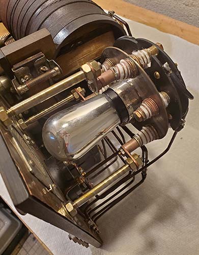
RF Driver SE-1387 - 215-A tube socket & fil control. The Oscillator tuning condenser is controlled with a two-speed tuning dial assembly.

The SE-1387 Details - This device was called an R.F. Driver, though nowadays that's an unrecognizable term that fails to describe the circuit's true function. It obviously tunes from 125M up to 30,000M (2400kc down to 10kc.) It uses a single WECO 215A tube that's designed to function as an RF oscillator and, when connected with the SE-143, it provided a electro-statically and variably-coupled RF oscillator that when tuned to the RF Tuner's operating frequency would provide heterodyne action for CW reception from Arc transmitters, Alexanderson Alternators and Vacuum Tube transmitters. This type of on-frequency heterodyne action allowed reception of the CW mode without requiring a self-oscillating detector (a regenerative Autodyne detector.) The heterodyne oscillator had to be tuned to the received frequency since these receivers were Tuned Radio Frequency circuits with no down-conversion of frequency as would be found in later superheterodyne receivers. Later, this on-frequency heterodyne reception method, when mechanically coupled to the receiver's main tuning function, was referred to as a "Tracking BFO" and it was employed in many types of shipboard VLF, LF and MW TRF CW receivers up through WWII.

The RECEIVER terminals route the SE-143 RF Tuner output (RA) directly to the GRID INPUT of the SE-1834's RF amplifiers. The SE-1387 (oscillator) output is from the variable coupling coil inside the unit that is connected in series between the SE-143's RE terminal and the lower AMPLIFIER terminal that connects through an adjustable wire-wound resistance to the B- connections within SE-1834 (the STABILIZER control.) The Coupling Coil adjustment should be placed so that the letters on the COUPLING control nomenclature matches the letter of the tuning range selected. From that setting of the COUPLING, the output can be adjusted by slightly varying the Coupling Coil position to provide sufficient heterodyning to the SE-1834 but to not overwhelm a weak CW signal. In simple terms, the tuned LC from the SE-143 is connected directly to the SE-1834's WE 215-A RF Amplifiers and the RF Driver provides a heterodyne at the received frequency for CW reception from VT, Arc or Alternator transmitters. For Spark or Radiophone reception the SE-1387 could be turned off (turn the INCREASE pot fully CCW - like turning off the BFO.)


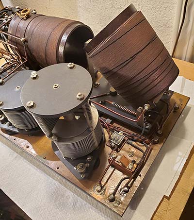
RF Driver SE-1387 - better view of Oscillator coils and the moveable shielded Coupling coil.


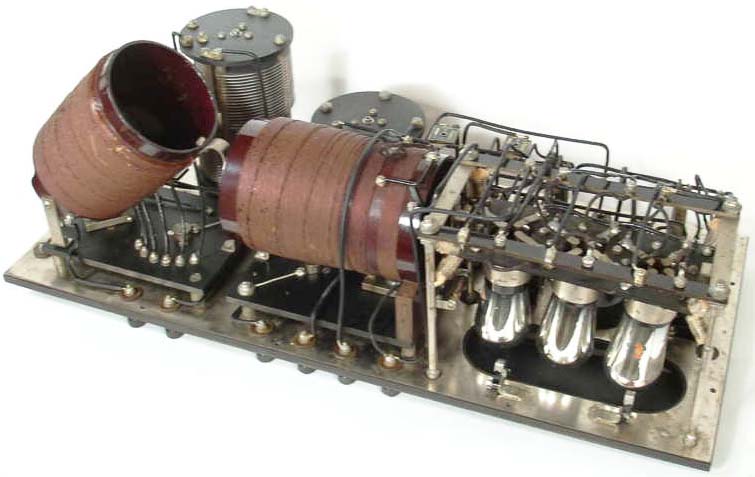
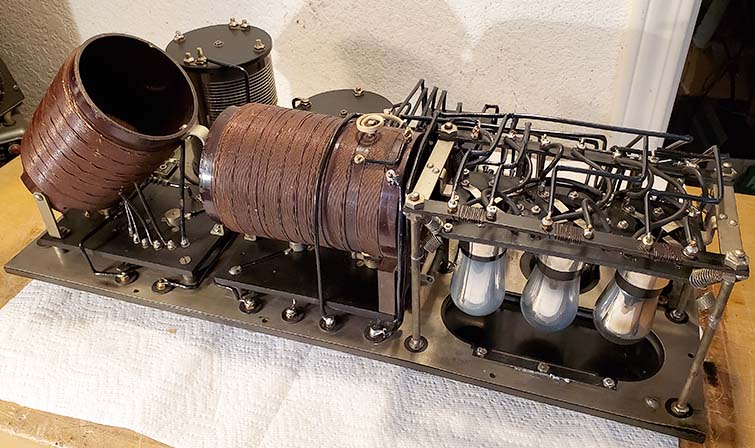
Universal RF-AF Amplifier SE-1834 - The front three units are four-band RF amplifier coils. The rear two units are Audio interstage xmfrs. The front three tubes are RF amplifiers, then the detector and the rear two tubes are the Audio amplifiers. The RF range switch selects one of four different, broadly tuned RF inductances in each RF transformer (selecting both the primary grid winding and the secondary plate winding.)

The SE-1834 Details - This is essentially a complete receiver minus any selective RF tuning. It uses six WECO 215-A tubes. The three stage RF amplifier uses three broadly-tuned RF transformers with their fixed-frequency ranges selected by the four position front panel switch (WAVELENGTH.) Each RF coil assembly has four RF transformers (primary and secondary windings) that are actually "iron core" transformers. The range of operation is 125M to 30,000M (or 2400kc down to 10kc in four ranges.) The amplified RF output is routed to a grid-leak detector tube that uses a glass grid resistance cartridge. If the SE-1387 RF Driver/Heterodyne Osc. is used, then the SE-143's Tickler coil doesn't need to be utilized and the strap between the two "TICKLER" terminals is installed. If just the SE-1834 is used, then the TICKLER strap is removed and two wires are installed to connect the SE-143 TICKLER terminals to the SE-1834 TICKLER terminals. The connection allows the SE-1834 Plate voltage to be routed through the 1st AF transformer primary to one of the TICKLER terminals, then to one of the SE-143 TICKLER terminals, through the SE-143 Tickler coil, back to the second SE-143 TICKLER terminal and back to the second SE-1834 TICKLER terminal where it then is connected through a glass resistance cartridge to the Detector plate. The Detector plate resistance was to lower the +40vdc Plate voltage supply to the normal Detector plate voltage of about +20vdc when used as a regenerative detector.


SE-1834 - Note the RF range switch. The meter is 2vdc FS and optimized for the 1.0vdc filaments of the WE 215-A tubes.

The complete set up using the SE-1387/SE-1834 Combo would have SE-143 RF Tuner operating with three stages of broadly-tuned RF Amplification, a grid-leak detector with the SE-1387 providing a CW heterodyne oscillator (manually tuned on-frequency heterodyne oscillator) and then two stages of transformer-coupled Audio Amplification. By turning off the SE-1387, the SE-143 operates as a standard TRF receiver and can demodulate signals from spark transmitters or Radiophone signals.

The Interconnection and Operation - The SE-143 RF Tuner was directly connected to the SE-1834's three stage, RF transformer-coupled RF amplifier by connecting the SE-143 RA and RE terminals to the RECEIVER terminals on the SE-1387. It was mentioned in the SE-143 manual that since the RA wire is a "grid connection" it had to be isolated, as much as possible, from other wires ("not bunched with the other wires" was the terminology used.) However, note that the SE-1387 terminals does provide a grounded SHIELD terminal implying that the RA/RE SE-143 connection should use a shielded cable. Internally, the RECEIVER terminals connect directly to the AMPLIFIER-GRID terminals and are "strapped" to the GRID INPUT of the SE-1834. This allowed the SE-143 a direct connection via its RA terminal to the first RF amplifier grid. The SE-143 Secondary LC ground-return is routed through the pick-up coil in the SE-1387 to allow the heterodyne oscillator to modulate the incoming signal to the SE-1834 RF amplifier grid (if the SE-1387 is powered-up.) Since the heterodyne is modulating the ground-return, there is a wire-wound resistance that's adjustable to "stabilize" the actual heterodyne versus signal ratio.

The RF amplifiers were broadly tuned via three RF transformers that provided four broadly-tuned ranges. This is essentially also where the incoming tuned radio signal was heterodyned with the SE-1387's variable-coupled oscillator output to allow detecting CW signals from VT, Arc or Alternator transmitters. The output of the 3rd RF amplifier stage was then routed to the detector stage. The output of the detector was routed to a two-stage, transformer-coupled audio amplifier. The audio output was routed to the TEL. terminals. Total gain was controlled by the filament voltage control and by the STABILIZER control. The purpose of the switch RADIO-AUDIO/AUDIO is to allow all filaments to operate in the RADIO/AUDIO position and turns off the filaments to the Detector tube and the two AF amplifier tubes in the AUDIO position allowing just the three RF amplifier tubes to operate (although this seems opposite of the expected function, measuring the continuity confirmed that the detector and audio tube filaments are turned off in the RADIO/AUDIO position. However, the nomenclature might imply using only the SE-1837 RF amplifiers ahead of the receiver's regenerative detector and audio stages.) The STABILIZER control is a wire wound resistance of the SE-143 RE connection terminal (secondary tuned LC ground return) to the B- line. The FILAMEOSTAT adjusts the filament voltage on the WECO 215-A tubes (set to 1vdc fil voltage.) For use of the SE-1387/SE1834 combo, the TICKLER terminals have the strap installed and the AMPLIFIER-GRID INPUT straps are also installed. If just the SE-1834 was used with an SE-143 RF Tuner, it would be possible to remove the TICKLER strap and use the TICKLER connections on the receiver for a regenerative detector. The RA-RE connections on the SE-143 would then be connected to the SE-1834 GRID INPUT directly.

There was an SE-1834A version that eliminated the filament voltage meter (shown in two of the vintage B&W photos further below.)

Circuit Analysis, Testing, Restoration - SE-1387 - There are no schematics available for the SE-1387 or the SE-1834. In fact, there's no documentation available, at all. I've had to trace the wiring to see what the circuits were intended to do when interconnected to an RF tuner like the SE-143. The circuit is a grid-leak oscillator with tightly coupled grid and plate coils. The grid coils connect to the variable condenser to allow the LC to function as a frequency adjustment. The range switch is double-function and selects both the correct grid coils and the correct plate coils simultaneously for a specific tuning range. The oscillator output is coupled by an adjustable "pick-up" coil (COUPLING) that is shielded with non-ferrous metal to allow magnetic pick-up only. The "pick up" coil connects in series between the SE-143 secondary LC ground return (lower Receiver terminal) and the lower Amplifier terminal. My analysis that the tuned oscillator is to provide an on-frequency heterodyne for CW reception is based on the increasing use of CW in place of Spark transmissions at the time and how later "Tracking BFO" TRF receivers were designed. Vintage photos helped to actually see how these devices were connected to the SE-143 in particular. However, the final analysis will be to confirm the SE-1387 does function as I think it should. This will require a functional WE 215-A tube. That should provide functionality for the SE-1387 and, with an oscilloscope and a LF-MW receiver, I would be able to see and hear the oscillator output. I've tested all of the coils in the SE-1387 and they all show continuity, so the testing will begin as soon as a good WE215-A is purchased and delivered. I did find a broken solder joint that was on the B+ buss to the plate coils (standard soldering technique of the 1920s using buss wire and "tack soldering" is very prone to breakage,...especially after 100 years on the Planet.) Testing has shown that the implied Filament voltage at the supply was 2.5vdc however, 2vdc is shown on the front panel.  This level allows the INCREASE pot to provide +1.0vdc to a .25A load at the tube filaments with the adjustment at about mid-scale (although the 215-A tube has sufficient emission well-below the +1.0vdc specification.) Also, A+ is connected to B- and both terminals are connected to the shield-chassis front panel ground. For initial testing (before I actually had a 215-A tube,) I used an RCA 864 tube that I connected into the circuit with clip-test leads. Amazingly, this did function exactly as expected but the final testing will have to wait for the 215-A tube.


The test set-up showing SE-1387 producing a 500kc (600 meters) waveform

The Test Set Up - I used an adjustable Lambda power supply with a voltage range of 0 up to +30vdc at 2.5A. I set the output voltage to +2.5vdc with the wires connecting to - and + FIL BAT terminals. The B+ power supply is an RCA dual bench supply with a range of 0 to +20vdc from each supply. I connected the two supplies in series to have +40vdc B+ with the wires connected to PLATE BAT + and - terminals. The SE-1387 monitoring was provided by the FNIRSI DPOS350P. This is a small, tablet-size, modern piece of multi-function test equipment that runs on a rechargeable battery. I'm using the oscilloscope to monitor waveforms. Also provided by the DPOS350P is the waveform frequency and the P-P voltage and a lot of other parameters of the waveform. Accuracy of the SE-1387 dial is good with 500kc showing slightly off from 600M. The 2.008mHz waveform showed 150M on the SE-1387 dial,...not bad for an oscillator that's over 100 years old.


Looking over the top of the SE-1387 showing the WE215-A tube installed, the 150K grid resistor, the non-ferrous metal shielded pickup coil and the grid-plate coils

Waveform on Range A at 150 meters or 2.008mHz
VP/P=230mv

215-A in SE-1387 - UPDATE: I've run into this problem many times, especially on 1920s tubes. When the 215-A tube arrived, it looked NOS in the original box, but testing the filament continuity showed it was open. Visual examination with magnification revealed that the filament was intact. I re-flowed the solder on the base pins and checked again. This time I had continuity. I did the same re-flowing technique on the grid and plate pins. When the 215-A was installed, at first it didn't oscillate. I increased the filament supply up to +2.5vdc with the INCREASE control about mid-point for about +1vdc on the filament. The 215-A started to oscillate. I checked ranges A and B with no problems in operation. Subsequent testing confirmed operation on all five ranges. The filament of the 215-A is oxide-coated so as the tube is used it should continue to improve emission. Attaining full emission usually takes about 30 minutes of operation if the oxide is thorium-based. From then on, the tube will function correctly at a somewhat lower filament voltage (unless it's left inoperative for another 100 years.)


Waveform on Range B at 600 meters or 500kc
VP/P=149mv

The Western Electric Co. 215-A tube - WECO 215-A tubes, also known as VT-5 or D-80039, are very similar internally to the WD-11 tube. However it's quite probable that the internal design of the later WD-11 that was used in Westinghouse-RCA battery operated Broadcast consumer radios from 1922 up to 1925 was actually based on the 215-A since Westinghouse and AT&T (Western Electric) were cross-licensed in the GE-RCA "Radio Group." The 215-A tube envelope and base are significantly smaller than the WD-11. The tube socket is unique and only fits the 215-A. Filament specs are 1.0vdc at .25A (WD-11 is 1.1vdc at .25A.) If the filament structure is like the WD-11/WD-12, then the 215-A uses an iridium-platinum ribbon that's oxide-coated. The 215-A behaves like a WD-11 in that filament emission takes place at a very low temperature and low current level (much lower than the .25A spec.) Most of the time, the 215-A filament isn't really incandescent at all but the emission is at specifications. In a day when a typical UV-201 tube required 5vdc at 1amp and the pure tungsten filament incandesced like a 5 watt lamp, the 215-A and the WD-11 behaved quite differently with many users unnecessarily increasing the filament current up to the point of filament incandescent visibility with disastrous results. Plate voltage maximum is +100vdc though usually the tubes are operated at +40vdc to +60vdc. The amplification factor is typically about 5 but could go up to 7 or 8 at higher plate voltages and if the tube has good emission. The 215-A tube was only used for a short time and was commonly found in the Western Electric Broadcast Monitoring Superheterodyne Receivers, like the 3-series and 4-series, also other WE BC monitors and apparently in a hearing testing device. Its common use was in the period of 1921 up to about 1928 although there are some indications that the Signal Corps had some use for VT-5/215-A tubes as late as the early-1940s. Although the WD-11, WD-12, WE239A and, the more modern replacement, the RCA 864 all have almost identical specs as far as the tube elements and function, the physical structure of these electrically-similar tubes is completely different. For initial testing, since I sold my collector tubes years ago that had included five good 215-A tubes, I'm going to have to buy seven of them,...ouch! The WE215-A is relatively inexpensive but the WE239-A is astronomically priced (WE tube dealers,...and for an anemic triode with an amplification factor of 5???) WD-11/WD-12 tubes seem to be somewhat fragile because most of the ones I've found had open filaments. I'm going to use the 864 tube for initial testing. It's a little more stoutly built and seems to function okay as a substitute. It's a moderately priced tube but I have several of them that didn't get included in the collector tube sale. I only used the 864 until I actually had a WE 215-A tube to use.

Circuit Analysis, Testing, Restoration - SE-1834 - Testing the functionality of SE-1834 is much more involved in that six WE215-A tubes are required for full operation. Point-to-point DCR testing has shown that both audio interstage transformers have good primary and secondary windings which is very helpful (and, yes, I do use that Triplett VOM for continuity testing as shown in the background of "The Test Set-up" photo above.) The 3rd RF transformer tests good for all four grid windings and for all four plate windings (it appears to be a vintage replacement.) The 2nd RF transformer has all four grid windings showing continuity but two of the plate windings are open (Band 1 and 4.) The 1st RF transformer has all four grid winding showing continuity but two of the plate windings show open (naturally, Bands 2 and 4.) All grid windings in the three RF transformers are good (that's 12 grid windings total.) Of the twelve plate windings, four are open and will need to be repaired. Due to the apparent failures in the plate windings involving all four bands, a bypassing of RF1 and RF2 would only leave RF3 in operation,...maybe okay for testing but RF1 and RF2 will have to be repaired for full operation. Due to the "iron core" type of RF transformers and the method of construction, any repairs to the windings will be difficult (but not impossible.)

All other components of SE-1834 test okay as far as DCR continuity. One broken solder joint was found. It was a buss wire that connected F+ from the STABILIZER adjustable resistor to the 3rd RF transformer grid buss connections. There are four spring-clip type holders that seem to be for grid-leak glass type resistors. Two are for the Audio tubes and are from the grid to B- which would imply they are grid-biasing resistors. I would guess the value would be 100K to 500K,...but that's just a guess. One other spring-clip is connected from the detector plate to the 1st AF interstage transformer primary winding. This implies that this also would be a resistor to compensate for the single +40vdc B+ to lower the plate voltage on the detector tube. The value would probably be less than 25K. The last spring-clip should be for the detector grid and should be a capacitor of about 250pf. So far, I haven't confirmed the detector grid connection. I found two, loose in the cabinet, glass capacitors that looked similar to grid-leak resistors but were marked ".002uf" on the inside (2000pf seems too high of a value for the grid-leak function.) These weren't installed but were wrapped in plastic and had been placed inside the cabinet. I'm not sure that any of the four spring-clips would use capacitors (although the actual grid-leak on the detector grid has to use a capacitor.) The circuit implies that resistance would be used. Drawing a schematic of the circuit would probably make the analysis a bit easier and certainly more accurate. Functional restoration of SE-1834 is definitely going to require complete disassembly. It appears that dismounting the tube socket chassis allows access to most of the components. To ease the process of disassembly and reassembly, a wiring assembly drawing (not a schematic) will have to be made.


SE-143, SE-1071, SE-1000 station at USN Station NAA. Those are impressive VLF loading coils. The tapped switches in front of the coils likely tune these inductances. This is a "non-posed" photo since the radio op moved his head during the exposure. Also the lighting and focus are not very good, however this is an incredibly valuable historical document of how radio equipment was set-up post-WWI.

Typical Vintage Set-ups using the SE-143 and various "add-ons" - The photo to the left shows a standard SE-143 set up with the SE-1071 Audion Control Box and the SE-1000 Two-Stage Audio Amplifier. These two accessories were the most commonly used accessories for the SE-143, especially towards the end of WWI and immediately after. On the right side of the table is another SE-1000 and SE-1071. Note the antenna coupler near the ceiling. This is part of USN Station NAA. Note that the SE-143 is tuned to a rather high frequency. It looks like about 400kc. Photo date is probably about 1920. This photo is all over the Internet but I got it from navy-radio.com

The photo to the right shows a much later Navy shipboard installation (note the open porthole to the upper left of the photo.) This installation is using the SE-143 and on top left of the receiver is the SE-1387 RF Driver (or a similar type like the SE-1372,) then a duo-lateral LF loading coil assembly (possibly a DeForest LC-100) and an SE-1834A (no filament meter so it's the "A" version) on the far right. Although this receiver-combo can function in all modes, the transmitter is a quenched-gap spark type (though it might not be the only transmitter onboard.) The full-size version of this photo is the "header photo" above and actually shows another USN Officer standing behind the radioman. On the wall behind that Officer is a calendar. This photo is exceptionally well-focused with an excellent camera lens and, although partially obscured by the Officer, the year on the calendar can be read and is "192-" with the last digit not visible. A believable date for this photo would be around 1925.


SE-143, SE-1387 (or SE-1372?) a set of Duo-Lateral VLF Loading Coils and, at the far right, the SE-1834A. The transmitter is a Quenched-Gap Spark Transmitter. Note that the SE-143 is set to "CRYSTAL" on the Detector Switch. This might have been for the SE-143 to interface with the SE-1834A in this particular set up. The tuned frequency is fairly high as indicated by the Inductance switches. It's likely this was a "posed" photograph but it's still extremely informative as to 1920s shipboard "hook-ups."


 From USN Station NAA: (R to L) SE-1420 Receiver, SE-1372 LF RF Driver (?), SE-1597 Loop Antenna Amplifier, SE-1834A RF amplifier, detector, AF amplifier and a Receiving Antenna Coupler (being held by RMC Gilmour)  ca. 1925

NOTE: As can seen in the photo, none of these devices are interconnected implying that the equipment was probably arranged for the photograph and not necessarily that all of the equipment was "used" together.

Other Receiver Types - Another set-up is shown to the left, from USN station NAA. The receiver on the right side of the photo is the famous SE-1420, a single-tube regenerative detector receiver. Next is the SE-1372, a three band, possibly a specialized version of the SE-1387 with less heterodyne frequency coverage. The next unit is a Loop Antenna Tuner, the SE-1597. The left most unit is the SE-1834A with the "A" being the version without the filament voltage meter. That's quite a Loose Coupler that RMC (Radioman Chief Petty Officer) Gilmour is holding though it's probably an antenna coupler of some sort,...note the similarity to the coupler in the photo above left. A believable date for this photo would be around 1925.    photo from navy-radio.com.

IF these accessory devices were to be used with the SE-1420 then some circuit changes would be necessary since the SE-1420 already has a detector. It would be possible to use the SE-1387 (or the SE-1372) by itself as a Heterodyne BFO ahead of the SE-1420 detector by connecting the SE-1387 output to the SE-1420 Antenna terminal (just wrapping the output wire from the SE-1387 around the Antenna lead wire should provide sufficient coupling.) Then the SE-1420's TICKLER/regeneration can be adjusted to the point just before the detector oscillates. The only thing accomplished would be to eliminate the oscillating detector and replace it with a heterodyne oscillator. Actually getting sufficient  regeneration for oscillation is highly dependent on the frequency tuned, the detector plate voltage and the antenna used. The lower frequencies are particularly difficult to actually get the detector tube to oscillate. It's impossible to get the detector tube to oscillate at VLF unless loading coils are installed and the SE-1420 doesn't provide terminals for installing LF Loading Coils. A Heterodyne Oscillator would tend to make CW reception easier for a wider frequency tuning range without the use of LF Loading Coils.

The left-most unit is an SE-1834A and it might be possible to switch the SE-1420 control to CRYSTAL-RF AMPL to access the SE-1420's RF tuner section only by using the SEC COND and XTAL terminals and run the SE-1387 (as described in the preceding paragraphs) with the SE-1834. No battery voltages would be required for the SE-1420 since only the Primary and Secondary LC tuners would be used. A lot of experimenting was certainly necessary with these various pieces of equipment to achieve an actual functioning "upgraded" receiver. Integrating the SE-1834A with the SE-1420 would provide a TRF receiver with 3 RF amplifiers, detector and 2 audio amplifier stages. Adding the SE-1372 or SE-1387 would provide a heterodyne oscillator for CW reception.


SE-1420, IP-501 and IP-501-A Receivers
History, Design and Construction, Performance Testing


Louis Alan Hazeltine

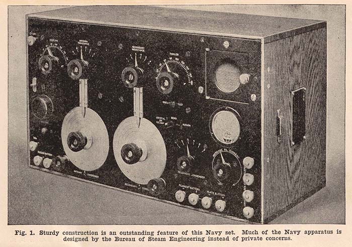
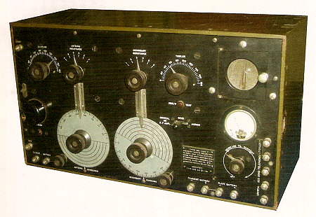
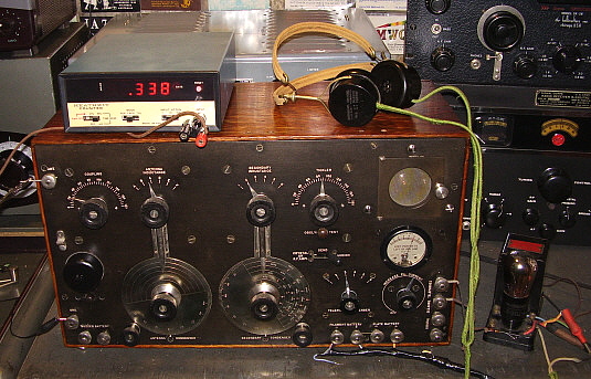
The SE-1420 was designed for the Navy at the close of WWI by Louis Alan Hazeltine, who was a Stevens Institute graduate and later taught there. Hazeltine, in addition to teaching at Stevens Institute, was also a consultant to the Washington Navy Shipyard. A former student of Hazeltine's, L.C.F. Horle, was the technical leader at the Washington Navy Shipyard and the laboratory there was responsible for radio receiver design. Horle engaged Hazeltine to design a new wireless receiver for military use. What the Navy wanted was a receiver that could operate in the presence of nearby spark transmitters without interference and would allow stable operation while the detector was oscillating for reception of arc transmitters.

The Bureau of Steam Engineering (changed to Bureau of Engineering in 1920) was in charge of Navy radio equipment at the time and most receivers were designated with the prefix "SE." Hazeltine's new receiver was going to be designated SE-1420. It borrowed a lot from its predecessor, the SE-143, in general appearance but, unlike its predecessors, the new SE-1420 was going to be a vacuum tube receiver. This went against all Navy tradition since the early days of spark. The Navy manuals of the day condemned the vacuum tube as "unreliable" and "power consuming."


photo from:  "How to Make Commercial Type Radio Apparatus" by Milton B. Sleeper - 1922
This Booklet profiles several commercial receivers and transmitters including the SE-1420 shown

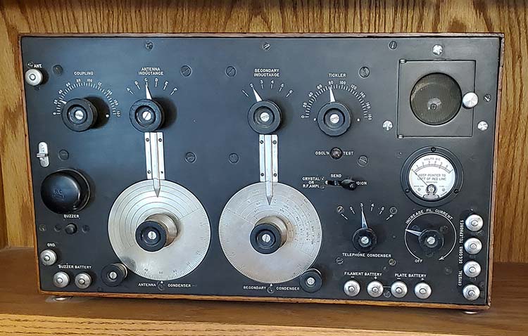
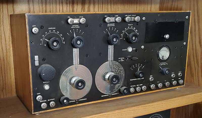
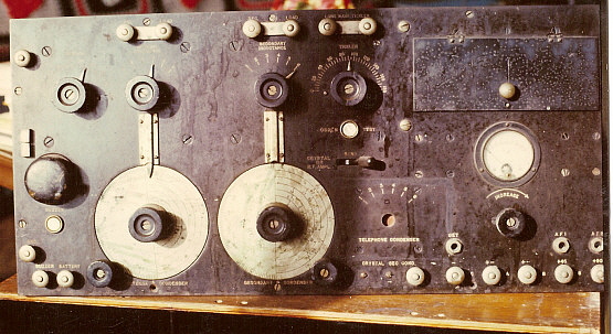
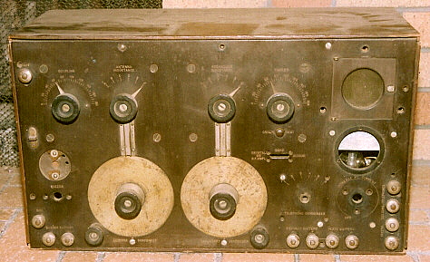
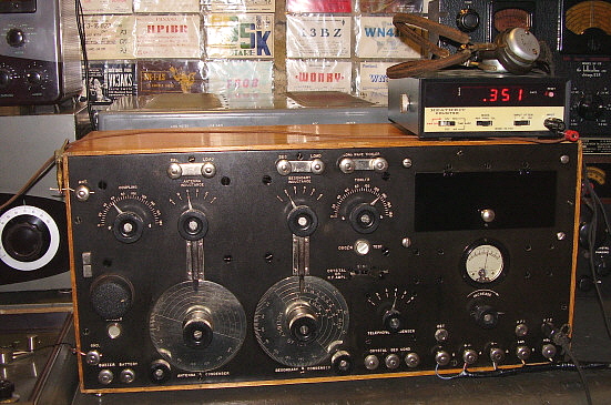
Wireless Specialty Apparatus version of the SE-1420, probably from a 1920 contract. Tunes from 300 meters to 7500 meters.  Serial Number: 270R

The Navy preferred the silicon detector because of its ease of operation and it reliable nature (what could go wrong with it? It was a rock!) Hazeltine was a vacuum tube expert, he had invented the term "mutual conductance" and thoroughly understood how vacuum tubes operated. He designed the SE-1420 to use a regenerative VT detector and to have the ability to greatly reduce interfering signals.

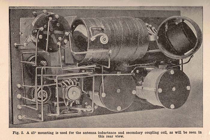
Hazeltine first utilized a three-circuit tuner, that is, adjustable tuning of the antenna circuit, variable coupling to the tuned detector grid circuit and the detector plate circuit, to provide excellent sensitivity. He then used a completely shielded cabinet and isolated the Antenna Tuner circuit from the Secondary Tuner circuit with another shielded panel. This complete shielding would eliminate any stray pick up, hand-capacity effects or any coupling between the two circuits. Using a sharply tuned Antenna Tuner helped to improve selectivity and reduce adjacent frequency interference. By using a small Coupling Coil mounted inside the Antenna Coil and only allowing the energy from the Coupling Coil into the Secondary Tuner, further reduction of unwanted signals was realized. The two main inductors used bank-wound Litzendraht wire coils to reduce capacitive losses. "Dead turns" on all switched inductances were grounded by the action of the switches to further reduce losses. All of these efforts increased the selective nature of the SE-1420's tuning ahead of the detector input.

The regeneration, called "TICKLER," was provided by a variometer that was built into the secondary inductor form. One stator coil of the variometer was connected to the secondary coil while the other stator coil was connected through the rotor to the plate circuit. The wiring connections provide for the proper phase reversal for coupling between the plate and grid circuits to occur. The adjustment of the rotor position within the variometer allowed resonating the L of the plate to the grid circuit for detector inter-electrode capacitance feedback and also simultaneously increasing the EM coupling by way of the EM field intensity of the variometer and its relationship to the grid tickler stator coil allowing positive detector feedback and oscillation at the proper physical adjustment of the variometer rotor.

The TICKLER adjustment controlled the sensitivity and somewhat the selectivity of the receiver. The TICKLER also would allow the detector to be operated as an Autodyne or oscillating regenerative detector. Since the detector was oscillating at the tuned frequency this provided a heterodyne action with the incoming signal that the allowed demodulation of an arc transmitter's continuous wave (CW) signal. When operated as an autodyne, the receiver requires complete shielding to eliminate hand-capacity effects and stout construction for stability.

The detailed design effort was necessary because all Navy (and most other maritime vessels) used either spark or arc transmitters which usually produced very broad spectrum signals. Early receivers were so insensitive and tuning so crude that the broad transmitted signal was usually an advantage at attracting attention. The inability to have simultaneous operation of nearby stations led to sharing "airtime" - a gentleman's agreement that allowed most wireless operators to co-exist. Wartime was a different situation however and better, more powerful transmitters required better, more selective receivers. As the spark gap transmitter was improved by employing an oscillation transformer that narrowed the bandwidth, the receivers became more sensitive but not necessarily more selective. They still responded to the fairly broad spectrum signals that prevailed. At the time the SE-1420 made its appearance, its ability to function in the presence of nearby spark and arc transmitters made it an instant necessity for all sea going vessels. The photo to the right is from Milton B. Sleeper's 1922 booklet.

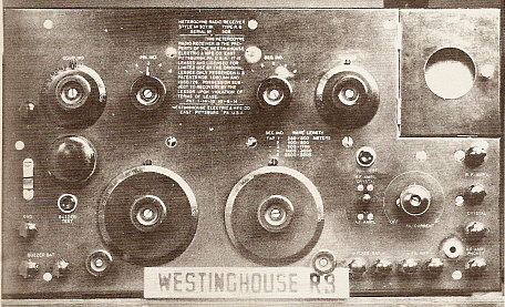
Several contracts were issued for SE-1420 receivers in late 1919. The initial contracts were for 400 receivers from AMRAD (American Radio & Research Corporation,) 400 receivers from Wireless Specialty Apparatus Company and 300 receivers from Sperry Gyroscope Company. These contacts were renewed and extended into 1920. Westinghouse designed their version of the SE-1420 receiver late in 1920, probably for use by the International Radio Telegraph Co., one of their subsidiaries. In 1921, Westinghouse submitted this version to the Navy for assessment but they were not offered a contract. Westinghouse designated their version as the Type RB Medium Wave Receiver and then offered it to the commercial user market but there was little interest and very few RB receivers were built. The various SE-1420 receivers will have some differences depending on the contractor and the time period of manufacture. AMRAD versions did not use a Telephone Condenser switch and mounted an ID tag on the front panel where the TC switch is on the WSA version. Also, AMRAD binding posts use hex nuts rather than knurled thumb nuts. "National Electrical Supply Company," a supplier of electrical and automotive parts located in Washington D.C., was added to the contractors rather early in the SE-1420 build history. "National Electrical Supply Company" is sometimes confused with Reginald Fessenden's company, "National Electrical Signaling Company" since both are usually referred to by the acronym, "NESCO." (Fessenden's NESCO was reformed into International Signaling Company in 1917 and then, after WWI, was purchased by Westinghouse to form their International Radio Telegraph Co.) Most National Electrical Supply Co. (NESCO) versions are very similar to the earlier AMRAD versions. Since AMRAD was bankrupt by 1924, later similar appearing versions are usually NESCO builds. 


The Westinghouse Type RB Medium Wave Receiver (this receiver was in Ralph Muchow's Radio Museum located in Elgin,IL)
 photo from Radio Age, Nov '82


The U.S. Army Signal Corps BC-131 version of the SE-1420C. This example has the olive-drab painted wooden case. This is an AMRAD contact receiver that was rebuilt as a BC-131. The modification tag is mounted below the AMRAD tag and identifies the set as the BC-131.  Photo from Antique Radio Classified, cover, Nov. 2006

Later Signal Corps versions are sometimes designated as BC-131 receiver. The later versions of the SE-1420 and IP-501 receivers will have less elaborate tube sockets that utilize a standoff mounted bakelite platform to mount a conventional bayonet-twist type tube socket. The filament ammeter on the early SE-1420 is a "live zero" meter with a .5-0-1.5A scale. The meter is generally marked as "CAY 260." Later SE-1420 receivers will have a DC Voltmeter rather than the CAY-260 current meter. The Westinghouse Type RB did away with the meter entirely.

Tube types used in the SE-1420 depended on the time period and the end user. In early receivers, generally, if the Navy used the SE-1420, a Moorhead Electron Relay (ER) was used as a detector, while the Signal Corps preferred the Western Electric VT-1. There were many variations of the Moorhead ER tubes with different manufacturers building them from 1919 up to the early twenties. Both the VT-1 and the ER tubes specify filament current rather than voltage (.5A@ ~3vdc for the VT-1 and .4A@~4vdc for the ER.) There were other tubes also available, like the military triodes that had the internal structure mounted so that when the tube was operated in the horizontal position (as in the SE-1420) the actual tube structure is in the vertical position. This prevented filament sagging that could happen with standard tubes operated in the horizontal position. Later SE-1420 receivers used the 201A and these tubes specify filament voltage (5vdc@.25A) The panel meters were changed from ammeters to dc volt meters as tube use evolved.

Apparently, many early SE-1420 receivers were rebuilt by the military as the receiver aged. This included upgrading the receiver to the SE-1420C or BC-131 configuration. This upgrading included adding a grid-leak resistor and capacitor assembly, usually mounted on the Secondary Inductor mount near the Tickler coil. Early versions of the SE-1420 relied on self-biasing of the detector tube and, although this does work, it requires fine adjustments of the filament and plate voltages for best results since there isn't a fixed negative bias source in the SE-1420. As vacuum tubes improved, the grid-leak arrangement worked better since it allowed for rectification (detection) and would "leak" off the excessive negative charges quickly though a high-value resistor.

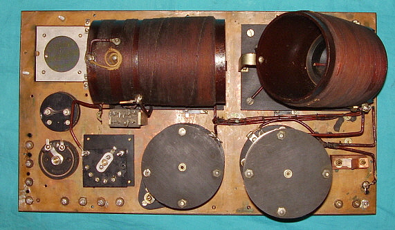
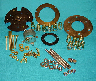
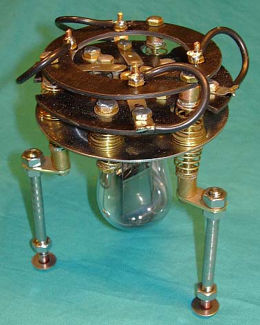
Several variations are seen of the replacement tube socket. The original socket is overly complex (77 parts are required to construct just the tube socket assembly) and was probably a constant source of problems. The simpler replacements are seen on rebuilt SE-1420 receivers and usually are utilizing the original stand-offs and lugs but have additional stand-offs to support a bakelite or fiberboard platform that has the tube socket integral with the platform. Some of the platforms seen are round, others are triangular. More than likely it depends on when the rebuild was performed, with the triangular platform being the latest version. Rebuilt receivers will usually have a newer ID tag mounted in place of the original tag or sometimes just an additional tag with the rebuild information. The cabinets were sometimes painted olive-drab when the Signal Corps converted the receiver to the BC-131 configuration. 

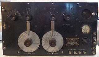
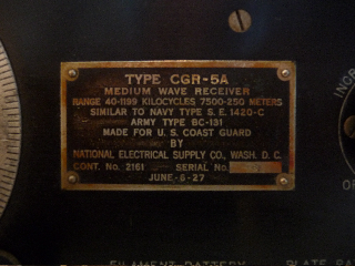
New SE-1420 receivers were built through most of the 1920s by several different contractors over the years. Shown in the photos to the right is the CGR-5A, made for the Coast Guard on a contract from June 1927. This version doesn't have the buzzer or the circuit selector switch and is housed in a metal cabinet. Also, the dial is calibrated in frequency rather than meters. The contractor on this particular CGR-5A was NESCO. This version also references itself to the SE-1420C as indicated on the CGR-5A data plate, "similar to Navy Type S.E. 1420-C/Army Type BC-131." The receiver shown belongs to Chris Dockery, who has also provided the photos. 


1927 - CGR-5A built by National Electrical Supply Company for the U.S. Coast Guard


The ID tag on the CGR-5A showing the contact date of June 6, 1927. The receiver was built sometime after that date.

History - IP-501 & Wireless Specialty Apparatus Company - In 1907, Wireless Specialty Apparatus Company (WSA) was formed by Greenleaf Pickard (who had cataloged over 1500 minerals and combinations that worked as detectors in 1903 - Pickard didn't discover the crystal detector, Karl Ferdinand Braun of Germany had invented the point-contact diode in the 1890s.) Additional WSA associates were Col. John Firth and his patent attorney, P. Farnsworth. John Firth also worked with Reginald Fessenden's NESCO at the same time and, probably because of this association, all WSA model numbers have the "IP" prefix which meant "Interference Preventer" - a Fessenden term for "selective tuning." United Fruit Company was an early user of WSA gear on their ships and in their shore stations. United Fruit Company had been somewhat in the radio business since 1903 and, in 1911, they bought WSA. Later, in 1913, United Fruit formed another radio company, Tropical Radio Telegraph Company, mainly for setting up and operating communications around their extensive property holdings in Central and South America. United Fruit was aware that their purchase of WSA gave them all rights to all Crystal Detector patents that WSA had through Greenleaf Pickard's association. The crystal detector dominated wireless receiver operation, especially through WWI. Right after WWI, the crystal detector patents were still of major importance and because of this patent, United Fruit Company was invited into the new cross-licensing agreement that was headed by General Electric and included Radio Corporation of America (GE's creation in 1919) along with AT&T (vacuum tube patents) and Westinghouse (Regenerative Detector and Superheterodyne patents and International Radio Telegraph Co.) With the cross-licensing agreement, these companies shared patents and products toward their advantage and tried to exclude most other companies and their competition by threats of lawsuits. The cross-licensing also allowed UF/WSA to now produce the SE-1420 for commercial users and have them sold by RCA (RCA hadn't created a division specifically to handle all maritime equipment and operate coastal communications stations - yet.). For the new commercial market, the designation of the receiver was changed to IP-501. A matching two-stage audio amplifier was now available, the Triode Type-B Amplifier. A Long Wave Adaptor was also available for operation at VLF frequencies. Though early versions may have used ERs or VT-1s, after about 1923, the IP-501 receivers used UV or UX-201-A tubes.


The IP-501 with Triode Type B Amplifier and Long Wave Adaptor.
    From: George Sterling's "The Radio Manual" 1st Edition - 1928


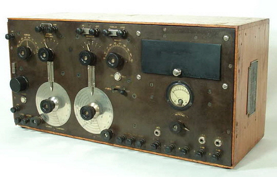
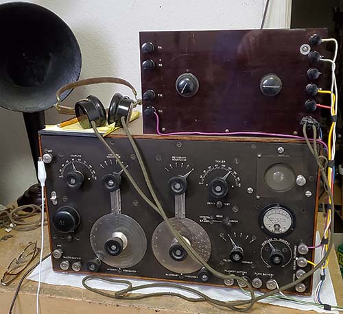
RCA/WSA IP-501-A from about 1923 to 1925, early version with Telephone Condenser switch and nickel-plated binding posts
 

History - IP-501-A & Radiomarine Corporation of America


In 1922, the IP-501-A was introduced. It combined the IP-501 and the Triode Type-B Audio Amplifier into one long cabinet. The consolidation made the IP-501-A easier to build since everything necessary was in one cabinet rather than two separate units as in the IP-501 and Triode Type B amp. The later versions of the IP-501-A eliminated the Telephone Condenser switch circuit and replaced all of the nickel plated binding posts with bakelite capped binding posts. At the time the IP-501-A was introduced, the general public had become interested in the new Radio Broadcasting. The market for entertainment radios sky-rocketed and most manufacturing concentrated on radios for broadcast reception. The commercial users were certainly not as numerous as the general public market and because of this the IP-501 and IP-501-A production level was never really very high. Wireless Specialty Apparatus built some home radios for RCA to sell, the AR1375, for example.   >>>

 >>>  RCA handled the sales of IP-501 receivers and accessories from around 1921 until sometime in 1923. By 1924, Wireless Specialty Apparatus disappeared from the scene, apparently purchased or absorbed by RCA. It's likely that RCA also acquired the WSA manufacturing plant in the deal since all later IP-501s and IP-501-As were built still using WSA parts. From 1924 up to sometime in 1927, RCA apparently carried on building receiver using WSA components and selling those marine receivers. In 1927, RCA acquired Independent Wireless Company and it was combined with Wireless Specialty Apparatus to form Radiomarine Corporation of America. Independent Wireless' Chas. Pennill became Radiomarine's Vice-President and J.P. Duffy came from RCA to act as Superintendent of Production. With the formation of RMCA, all marine operations and sales were then transferred to Radiomarine Corporation of America as a division of RCA. RCA had been operating many of the coastal wireless stations and providing "Radiogram" communications and those responsibilities were passed on to Radiomarine.
  

By the late twenties, the IP-501 family of receivers were beginning to show their age. The later versions eliminated some of the unnecessary or expensive circuits and parts but the basic style was still easy to recognize. Many receivers were still in use well into the late thirties. Their operation was easy, they were reliable and their excellent performance in the hands of experienced radio ops had resulted in the receiver becoming the "standard" shipboard receiver for at least a decade and a half. Advertising for RMCA was still using photographs of shipboard installations showing the IP-501-A as late as the post-WWII time period. The selling price of the IP-501-A was $550 in 1922 (listed in "Radio Enters the Home," a catalog of products available through RCA though built by WSA at this time.)
 

By 1930, RCA had acquired most of the patents and power that had formerly been shared by the GE-Westinghouse-AT&T Group as part of a settlement of an Anti-trust suit brought by the government. That resulted in the consolidation of RCA into the omnipotent corporation that controlled everything in radio in the thirties and forties. By the thirties, RMCA was running many of the coastal marine stations that provided Radiogram service to ships at sea. RMCA built marine radio gear that was installed on commercial ships. During WWII, RMCA supplied the Liberty ships with radio gear. Around the mid-1960s, RMCA was eliminated as a division and RCA handled all of the maritime business directly - at least, what was left of it.
 

United Fruit Company went on to political involvement in some Central and South American countries in an effort to protect and/or enhance their extensive banana and pineapple properties. Eventually, United Fruit Company merged to become United Brands (in 1970) and then was reorganized in 1984 as Chiquita Brands International.

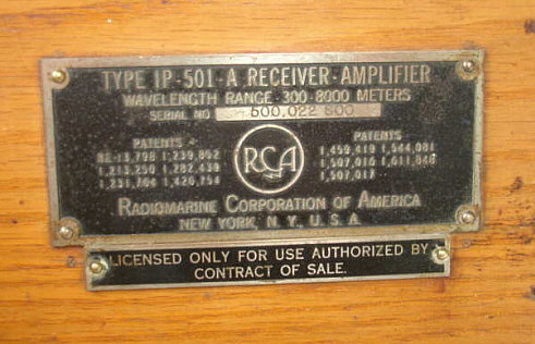
The photo left is a close up of the ID tag of an IP-501-A showing Radiomarine Corporation of America as the builder of the receiver. This tag is from the receiver shown in the photo right - a beautiful later version of the IP-501-A. This receiver is probably from the 1927 to 1930 time period. Note that the telephone condenser switch was eliminated and bakelite capped binding posts are used on these later receivers.

both of these great photos are from: Grant Kornberg - "TechnoGallerie"

Receiver Circuit and Construction Details
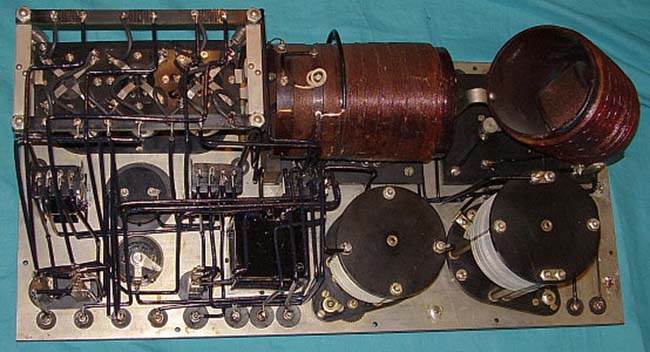
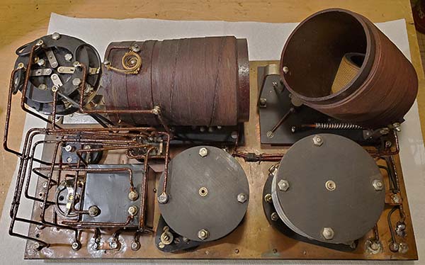
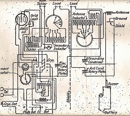
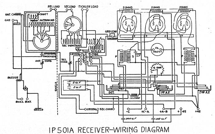
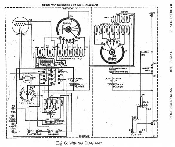
One look into the SE-1420, the IP-501 or the IP-501-A reveals an approach to construction where reliability was a major consideration, along with superior performance and ease of operation. The receiver uses a three-circuit tuner with regenerative/autodyne detector. The IP-501-A includes a built-in two-stage audio amplifier. The Antenna Tuner and Secondary Tuner circuits and the Detector circuits are similar in all receivers. The Antenna Tuner is labeled "ANTENNA INDUCTANCE" and "ANTENNA CONDENSER." The condenser is gear driven and the dial is calibrated 0-180º on its graduated scale. The Inductance taps are switched, "dead turns" are shorted to ground and an articulated pointer shows which band or scale is used. The Antenna Condenser dial has no nomenclature other than the 0-180º scale and ample room was provided on the upper non-scaled area for the operator to write in any markings he needed. The "COUPLING" control rotates a small coil located at one end of the Antenna Coil. The wires from the Coupling Coil are placed next to the front panel shield and then routed through a small opening at the base of the vertical shield that divides the cabinet into two shielded compartments. Only the energy within the variable Coupling Coil is transferred to the Secondary Tuner circuit. The shielding provides complete isolation and eliminates stray pick-up or any hand-capacity effects when operated as an autodyne detector. What comes down the antenna and is tuned in the Antenna Tuner circuit is then variably coupled into the Secondary Tuner circuit. This provided the excellent selectivity necessary for operation of the receiver in the presence of nearby spark and arc transmitters.

The Secondary Tuner circuit is labeled "SECONDARY CONDENSER" and "SECONDARY INDUCTANCE" - this is the main station selector tuning. The Secondary Inductance control selects the tuning range via the tapped inductance, "dead turns" are shorted to ground and the Secondary Condenser tunes the receiver frequency within that range. An articulated pointer shows which tuning range has been selected. On the IP-501 and IP-501-A, the Secondary Condenser dial is scaled in both Degrees and Meters with the various bands covering 300 meters up to 7500 meters, or approximately 1000kc down to 40kc and the condenser is gear driven, (most receivers will tune 1200kc down to 37kc.)
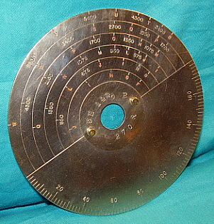
In some photographs, it appears that the first SE-1420 receivers may not have had a calibrated "SECONDARY CONDENSER" scale other than the 0-180º scale. If this was the case, it wasn't long before a meters calibrated dial scale was incorporated. That was followed by a dial with a meter scale and with important wavelengths marked off with letters. This must have been in reference to military wavelength assignments designated with letters because the SE-1420 lettered scale runs from "F" = 300 Meters up to "W" = 7500 Meters. The lettered scale is red while the meter scale is black. Late SE-1420 receivers, e.g. CGR-5A 1927, had dial scales calibrated in frequency rather than meters.


Secondary Condenser dial from an SE-1420B receiver showing lettered scale. Also note that the receiver serial number is on the dial, "270R."

The detector is a regenerative type using a variometer and tickler built onto the secondary coil form. Variometer controlled regeneration relies on detector tube inter-electrode capacitance and the EM field coupling of the variometer rotor position relationship to the tickler coil (which is one of the stator coils inside the variometer.) For reception of damped wave spark transmitters using rotary gaps the "TICKLER" is adjusted to a setting just before the oscillation point. If an arc transmitter was to be received then the "TICKLER" can be set into oscillation to allow a heterodyne action (autodyne detector) to hear the arc signal since it is continuous wave or CW. For the reception of a voice transmission via AM, the "TICKLER" would be set to just before oscillation occurs. The greatest sensitivity and selectivity occurs just at either side of the oscillation point in a regenerative detector and that is usually where the operator would adjust his "TICKLER." Since the load on the "TICKLER" (plate variometer) is fairly constant (because of the Antenna Tuning) there is very little change in where the "TICKLER" is set until the receiver is operated below 100kc. Since the regeneration is tuned, lower frequency reception requires a little more total variometer inductance so the "TICKLER" control will have to be increased (higher on the scale) as frequencies below 100kc are tuned. The "TICKLER" tunes total inductance in 90º of rotation (sign changes happen in quadrants) but, depending on the receiver, all "TICKLER" action is usually centered around 45º and increases to 90º as the lowest frequencies are tuned. The push button switch labeled "OSCL'N TEST" is for testing if the detector is actually oscillating or not. If the button is pushed and the detector is oscillating a "click" will be heard in the earphones. No click means the detector is not oscillating and the "TICKLER" control needs to be adjusted. Detector tube is normally a UV/UX-201-A.

Inside the RCA/WSA IP-501-A showing the heavy-duty construction of the receiver. The Coupling coil can just be seen inside the Antenna Coil, far right. Note the Ni-Chrome resistors wound on the bakelite wire terminal carrier over the tube socket assembly. The Telephone Condenser switch, the condensers and the choke are contained inside the black metal box next to the Secondary Condenser. Mid-production receivers use black sleeving over the buss wiring.


Inside the WSA SE-1420 showing the same heavy-duty approach to construction used in all of the shipboard receivers. Note that the SE-1420 shielding is not plated but is bare copper sheeting. Early receivers use a reddish-brown sleeving over the buss wire. See text in "Restoration" section  regarding the black metal boxes that are covering the Telephone Condenser switches in both our SE-1420 and IP-501-A.


The Antenna Condenser (r) and the Secondary Condenser (l) from an SE-1420 receiver showing the gear drives. Note that the idler gear is fiber so no lubrication in required and it is also insulating the main drive gear from the fine adjustment gear.


The Antenna Tuner section of the IP-501-A. Note the gear drives on the Antenna tuning condenser. Also, the Buzzer coupling to the Antenna circuit can be seen (the wire coil wrapped on the antenna inductance wiring.) The fixed condenser connects B- to ground (shielding.) The fixed condenser is a .012uf Faradon - the WSA/RMCA brand name.

 The audio amplifier circuit used in the IP-501-A is a standard two-stage type using interstage transformer coupling. The AF interstage transformers are typical RCA units and probably were products of that company. The ratio is around 3.5:1. Tubes normally used were UV/UX 201-A. There are ni-chrome windings on the bakelite wire carrier of the tube socket assembly. These provide about 1ohm resistance in the filament line to each tube as filament protection in case one of the tubes was removed with the A+ on. C bias voltage is used on both AF amplifier grids. The AF amplifier plates are usually run at 90vdc B+ and the C bias is usually -4.5vdc. The Detector plate is run at 45vdc B+. Filament control telephone jacks are used for output and the three provided allow for Detector only, Det.+1AF or Det.+2AF operation. Insertion of the 'phone plug  into one of the jacks will determine which tube filaments are lighted. A panel meter shows the applied filament voltage which is adjusted with the control "INCREASE."  On SE-1420 receivers, the panel meter measures current drawn by the detector filament. It was changed to a voltmeter early in the IP-501 production. The early versions of the SE-1420 are wired with the input ground "floating" and tied to the shield and B- through a fixed capacitor. This was changed in later versions to have the shielding connected directly to the input ground and then the B- connected to the shield through a fixed capacitor.
 

The "TELEPHONE CONDENSER" switch allows selecting various values of input capacitors to the RF pi-filter that is connected between the output of the TICKLER variometer and the audio output line. The RF pi-filter also uses a series iron core choke and a fixed output capacitor. The selectable input capacitors allow varying the audio response, specifically rolling off the high frequency audio. This is particularly effective for relief from static and other atmospheric noise. This function is only on the WSA versions of the SE-1420. It is also on the early versions of the IP-501 and IP501-A. The TC switch was never used in the AMRAD SE-1420 and was eliminated from the later versions of the WSA receivers. The TC switch was really not a necessity. It was probably installed on the WSA receivers for shipboard operation where static and antenna noise can hamper reception. RCA/RMCA eventually eliminated the TC switch, probably because of expense, potential problems and the fact that an optimum fixed-value capacitor resulted in effective static relief along with increased reliability by eliminating the switch.

The SE-1420, IP-501 and the IP-501-A all provide operations with crystal detectors utilizing the low-capacitance lever switch labeled "CRYSTAL OR R.F.AMPL" - "SEND" - "TUBE" ("AUDION" on SE-1420 sets.) Usually the standard crystal detector used was the "Three Detector Stand" that WSA offered. Typical shipboard operation had to provide for the possibility that all of the vacuum tubes, those in the set and the spares, could be destroyed during wartime with a possible torpedo hit. There was also the possibility that given enough time and bad luck all tubes and spares might just fail while still at sea. Or, maybe the batteries might need charging or replacement and there were no spares. In other words, many different things could affect whether or not the vacuum tubes could be used. The crystal detector was the back-up and it always would work.

The "BUZZER" provides a "signal generator" of sorts. When looking for a sensitive spot on the crystal detector, it would help if a really loud signal was present. Pressing the buzzer button will actuate a small mechanical buzzer that arcs and creates tremendous wideband RF. This is coupled into the antenna circuit with a brass sleeve capacitor on the wiring to the Antenna Inductance switch on SE-1420 sets and by a wire coil wrapped around the same wiring in the later receivers. The buzzer battery is usually a 1.5vdc dry  cell battery. It's not critical, but 2vdc was considered the maximum for the buzzer. DO NOT PRESS the buzzer button (with Buzzer battery connected) while in the vacuum tube mode of operation - if you do and you're using 'phones in the AF2 jack, the resulting "signal" will be so intense that you probably won't be able to hear anything for a few minutes afterward (yes, I did it.) The Buzzer circuit was only for finding a sensitive spot on a crystal detector. Additionally, a Long Wave Adaptor was sometimes used if operation below 40kc was needed. This unit sat on top of the receiver and its connections match the binding posts located at the top of the panel on the IP-501 and the IP-501-A (the Long Wave Adaptor units were not used with the SE-1420.) The Long Wave Adaptor had series inductors inside that when connected allowed the receiver to tune down into the VLF part of the spectrum.


The Secondary Inductor switch assembly. Tickler control  is on the right. Note the vertical gear-driven "lifter" for the dial pointer. The wooden shaft under the TICKLER control is the OSCL'N TEST button. This unit is from the SE-1420 receiver.


The copper shielding inside the IP-501-A cabinet is painted black. Note the divider shield and the small notched opening that allows the two wires from the Coupling Coil to pass through to the Secondary Tuner. Also note that the tapped screw mounts that allow the panel to be mounted are connected to the box shielding and these mounts also contact the back panel shield for a completely shielded enclosure.

The oak box that the receiver is mounted in is entirely lined with copper sheeting to act as the shielding. Complete contact is assured by way of the metal screw mounts that contact the receiver's panel shielding. Early receiver boxes sometimes had a front cover that was held on with bale clamps. The ID tag is located on the side of the box and these are almost always missing. This was probably due to the "military surplus" regulations of the time that required all mil-tags to be removed before sale. Something about if the tag wasn't there then the unit wasn't stolen. This regulation may have also applied to commercial surplus. Weight of the box with all of the copper inside is substantial and the entire receiver is quite heavy for a battery operated receiver - about 40lbs for an IP-501-A. The box for the SE-1420 is similar in construction but the shielding is not painted and is left bare copper. The finish on the SE-1420 box is somewhat dark, usually about the color of "iced tea." The later IP-501 and IP-501-A receiver boxes are finished in golden oak. Most BC-131 boxes are olive-drab paint. The front panels are .312" thick and is made of "Hard Rubber" sometimes called "Condensite" or "Bakelite-Delecto." This material is not brittle like bakelite or formica. The manuals say that the panel can be wiped with oil to protect it. Probably, with all of the salt-air present onboard a ship at sea, wiping oil on the entire panel, dials, knobs and cabinet would have gone a long way to protect the receiver's overall finish.

All screw and nut connections in the receiver are tightened and then soldered. This method is also used on the mechanical assembly. Soldering is easily accomplished since all of the hardware is nickel plated brass. This securing of all joints with solder was necessary because of the constant vibration of the ship while at sea in addition to adding protection from salt-air corrosion problems. The solder joint itself is not particularly strong and can easily be disassembled, however, much like modern "loc-tite," it was meant to keep the screws and nuts secure after tightening.


Restoration and Operating the SE-1420, IP-501 and IP-501-A Receivers

Restoration shouldn't be desired or even considered if your receiver is complete and original. However, this is by far the minority of surviving SE-1420, IP-501 or IP-501-A receivers. Most of these great receivers were destroyed in the past 80+ years by scrap dealers, by the scrap drives of WWII, by parts dealers, by surplus dealers selling to "hamsters" and just by years of abuse, poor storage and neglect. This section is for the restorer that wants to have his incomplete receiver as accurately restored as possible and to have it operational and functioning correctly.

Most SE-1420, IP-501 and IP-501-A receivers that are found today are far from complete. It isn't unusual to find the receiver missing all of its buss wiring or missing major components and almost always some of the minor parts will be gone. I one time found the Antenna Tuning Condenser of an IP-501 that had been "sawn" out of the front panel - not dismounted from the panel - just sawn out, panel and all. Such destruction was common. Anything is possible to find since these receivers were considered surplus unusable junk in the forties and fifties. How likely your receiver is able to be completely restored depends on your interest, your abilities at replicating parts and how much of the receiver you have to start with.

Generally, the major parts necessary for considering a complete and functional restoration of the receiver are:

1. Both Antenna and Secondary Inductors - including Coupling Coil and Tickler Coil. The Inductors are bank-wound Litzendraht wire and have multiple layers and taps that are wound on machine grooved forms - difficult to replicate. The Inductor switching is also a complex assembly.
2. Both Antenna and Secondary Condensers - complete with gear drives. These condensers are also very complex assemblies.
3. Complete Front panel and all shielding - includes both main dials
4. Cabinet and cabinet shielding - though the receiver will operate without the cabinet, it's complete shielding is an important part of the design.

Most of the other parts can be found or replicated. Some parts are not too difficult to find even today. You will probably have to adapt some of the parts from 1920s TRF battery radios. Many times these are the exact same parts anyway. Knobs can be cast or professionally reproduced. Hardware can also be machined and nickel plated. The amount of work necessary is sometimes daunting but patience is required when restoring receivers that are now exceeding 100 years of age.

SE-1420, IP-501 and IP-501-A  -  Schematics and Documentation

Documentation is very important when restoring the SE-1420, IP-501 and IP-501-A receivers. To say that they were poorly documented would be an understatement. None of the schematics available are complete. Most will provide a general idea of how things are connected but details are certainly lacking. The various schematics are shown in several books, e.g., Elmer Bucher's book on Wireless Equipment or early editions of George Sterling's Radio Manual or others, but all are incomplete schematics that are only provided as general information. The IP-501 schematic shown to the right is about as good as they get. Not a lot of details but it is basically complete and does show the connections to the complicated "Circuit Selector" switch. However, mistakes are common, e.g., the "Grounding Condenser" is not a variable, it is a fixed condenser. This schematic is good for the IP-501 produced around 1922. Earlier SE-1420 and the later IP-501-A are very different receivers. What one has to do is use good photos of the interior of original receivers combined with the information provided in the better schematics to ascertain what is correct for your particular receiver. This is assuming that your receiver needs to be restored and is missing some of the original buss wiring or original components. Be aware that the buss wiring techniques and routings changed over the production period, so early receivers look very different inside from the later versions of the same model. Interior photos are the most helpful to determine what is correct.

Operator's manuals are around. Some are available on the Internet and some basic operating instructions are included in various books. Sterling's "The Radio Manual" has instructions for both the SE-1420 and the IP-501, along with the Long Wave Adaptor. However, these instructions are brief, contain very few details and are not completely accurate anyway. No details are provided about typical antennas for the receivers. The RCA and RMCA manuals are by far the best and most accurate.

Helpful Hints in Restoring the SE-1420, IP-501 and IP-501-A Receivers

Synchronizing the Tickler Variometer - The variometer has to increase total inductance with the proper sign (+ or - are used to indicate the increase or decrease of total inductance as the rotor turns inside the stator coils) as the pointer is advanced up the TICKLER scale. This results in the receiver requiring higher TICKLER settings as the wavelength is increased (lower frequency.) The correct wiring is the detector plate is connected to one coil of the variometer stator as the input. The grid circuit is wired to the other stator coil to provide the feedback path. The variometer rotor output (rotor-front) goes to the Circuit Selector Switch, RF pi-filter and on to the audio output and detector B+. To check that the variometer is synchronized, place the TICKLER pointer straight up on the scale. Look at the variometer rotor just visible on the shortwave side of the Secondary Inductor and you should be able to see the wire splice joint that connects the two rotor inductors together. If you don't see the splice joint then the rotor is 180º out. Remove the TICKLER knob and pointer, then rotate the variometer rotor so that the splice joint side is visible, then re-install the knob and pointer with the pointer straight up on the scale (or nearly straight up.) Check the flexible connections on the variometer rotor to make sure they aren't coiled too tight at each extreme of TICKLER adjustment. NOTE 1: Although you do get a change of total inductance through each 90º of rotation with a variometer, the two 90º quadrants in 180º of rotation are of opposite sign + or - (there is a mutual inductance change also.) When the variometer is operated in the opposite two 90º quadrants, the receiver will not regenerate on lower frequencies or will oscillate uncontrollably due to improper phase relationships to the grid coils. With the proper variometer synchronizing the receiver's oscillation is controllable on all tuning ranges.
NOTE 2
: Some receivers (early SE-1420s) will have the variometer rotor mounted slightly off so that the angle of rotor rotation is not 0-180º. This was probably to allow the TICKLER adjustment to be more "mid-scale." Later receivers have 0-180º rotation and most of the TICKLER action is located in the 0-90º portion of the scale (as would be expected.) This allowed plenty of regeneration at the lowest frequencies that the receiver would tune to since this was about mid-scale (90) on the TICKLER adjustment.

Dismounting the Primary and Secondary Condensers - The condensers are mounted using 10-32 screws and nuts with stand-offs between the condenser mounting plate and the back of the panel. The nuts are secured by soldering after assembly. To remove either condenser first remove the associated fine adjustment knob and the dial by removing the large knob and collar, then remove the dial. The dial is only held in place with two locating pins and should easily come off. You will now see that the flange that the dial mounted to will just barely fit though the hole in the panel shield. You have to be careful not to bend the shielding too much when removing the condenser otherwise you will end up shorting the condenser to the shield when reinstalling the unit. Unsolder the buss wire connections to the condenser. Then remove the screws and nuts. The soldered nuts will come off easily. Solder is not particularly strong and usually with a open-end wrench on the nut and a large screw driver on the screw head, the solder joint comes loose with minimum effort. You can also heat the joint up with a larger soldering gun or iron and then break the joint loose. Heated solder is even weaker and the screws will loosen with almost no effort. After the screws and nuts are off, carefully rotate the condenser assembly while lifting it off of the panel. You will find some interference between the panel shield and the dial flange but by rotating the assembly, the flange will clear the shield hole. Be sure to check the shield hole for bends - it should be straight and even with the back of the panel. Be sure to keep track of the four stand-offs. Remount in the reverse order.

Dismounting the Primary and Secondary Inductor Assemblies - Fortunately, the inductor assemblies are held to the panel with 10-32 flat-head screws that are not soldered. They screw directly into threaded stand-offs that are mounted to the assemblies. Remove the associated knobs and pointers. Disconnect the buss wires going to the inductor assembly. Remove the four 2-56 screws that hold the dial pointer cover-guide to the panel. The pointer has a .125" diameter pin that is a push-fit into the lifter mechanism behind the panel. Remove the dial pointer. The pointer should be slightly twisted while pulling it away from the panel. The pin fits into a bakelite holder, so it should come off with very little effort. Remove the four 10-32 flat-head panel screws and lift the inductor assembly from the panel. Remount in the reverse order.

Dial Pointers - These are rather complex assemblies for the simple job they do. The "lifter" mechanism is located on the associated inductance assembly. The lifter is gear driven by the inductance switch and the lifter itself is attached to a rack gear. Two guides keep the rack's alignment. The lifter has a "L" shaped bakelite piece that the pointer pin is inserted into. The pointer itself is mounted to the front panel by a two-piece cover-guide that is nickel-plated. The cover-guide is mounted to the front panel with four 2-56 round-head machine screws. To remove the pointer just take out the four guide screws, remove the cover-guide pieces and remove the pointer from the lifter by pulling it away from the panel. If you need to work on the lifter mechanism itself, you will have to remove the associated inductance assembly.

Automatic Filament Control Wiring for IP-501-A - I've not seen a schematic for an IP-501-A that shows the wiring of the Automatic Filament Control Jack system. However, the system was used in several other battery operated radio receivers/amplifiers and the wiring should be the same. The telephone jacks have to control both filament voltage and plate voltage based on into which jack the telephone plug is inserted. This requires special telephone jacks that have enough auxiliary contacts to accomplish the switching based on whether or not the plug is inserted. Federal Telephone & Telegraph Company was a major supplier of Automatic Filament Control Jacks. The following information is from the 1923 Federal Tele. & Teleg. Co. catalog and show the jacks required, their identification numbers and how to connect them for automatic operation of the filaments in a Det + 2 Stage AF Amp, like the IP-501-A uses. Click: Automatic Filament Control Jack & Circuits

Buss Wire Details - Buss wiring changed as production methods evolved. The early SE-1420 receivers use a reddish-brown varnished tubing (spaghetti) for insulation. The wiring style for these receivers is very square and the buss wires actually run much longer than necessary. This was for appearance and was typical of the style of wiring at the time. When the IP-501 and IP-501-A were being produced by RMCA, the varnished tubing was changed to black. The style of wiring also changed in that the runs are much shorter and though still somewhat square looking, there are some angles and bends that are for better durability or performance rather than appearance. The late IP-501-A receivers still use black varnished tubing but more and more the square-look is giving way to more direct connections. Finally, in the 1927 CGR-5A (SE-1420C) the spaghetti is entirely eliminated and enameled buss wire used. When replacing missing buss wire, try to find an interior photo of a comparable receiver for reference. Buss wire was usually 13 gauge tinned-copper, which is impossible to find. I have used 14 gauge and 12 gauge, both work fine, although the 12 gauge is more difficult to work. Before using either size, the wire should be "drawn" - that is stretched by anchoring one end and then pulling the other - hard. This straightens the wire and slightly reduces it's diameter. It will make the buss wiring look very straight and professional. 

Chronology of SE-1420, IP-501 and IP-501-A Development and Production

1918 - Initial design of the SE-1420 by Louis Hazeltine
1919 - First contracts for the SE-1420 - AMRAD, WSA and Sperry Gyroscope
1919 - RCA is formed from GE assets and purchase of American Marconi Co. (Nov-1919)
1920 - SE-1420 contracts are extended
1920 - Cross-licensing with GE-RCA group allows WSA to offer SE-1420 as commercial IP-501
1921 - Design of the IP-501-A
1922 - IP-501 and IP-501-A available from RCA acting as sales agent
1923 - Likely purchase of WSA assets by RCA.
1923 - SE-1420 contracts continue, National Electrical Supply Co. added to list of builders
1925 - Production continued on IP-501-A using Faradon and WSA parts by RCA
1927 - Official formation of Radiomarine Corporation of America
1927 - IP-501-A updated - eliminated Telephone Condenser switch, bakelite capped binding posts
1927 - CGR-5A (SE-1420C) contract, National Electrical Supply Co., June, 1927
1928? - Production continues through 1928? 1929? 1930?...
1930s - Manuals date-stamped as late as Dec.1938 were provided by RMCA
1940s - IP-501A receivers used up to 1940, removed prior to and during WWII

Restoration of the IP-501-A

Back in 1979, I bought this IP-501-A from a ham friend who had traded a telephone pole for it. The price of $75 took into consideration the substantial amount of work that was going to be required to restore the set. Back then, with no Internet, all parts had to be advertised for in Radio Age magazine with the hope that one of the many collector-readers might have what you needed and would be willing to sell the part. It wasn't unusual for part locating to take a year or more. The IP-501-A was missing almost all of the buss wiring, it had the incorrect AF transformers, the Telephone Switch was gone along with the correct tube socket assembly. Additionally, the set's front panel was in pretty rough condition as were all of the nickel-plated hardware parts. The cabinet was actually in pretty good condition and the parts that remained were also in good condition. My first restoration just got everything cleaned up and looking good but I didn't want the IP-501-A to be just a "shelf queen" so I began to advertise for specific parts I needed to get it operational. That resulted in the second, functional restoration. I used black plastic tubing for the "spaghetti" on the new buss wiring and the interstage transformers were two old Jefferson units. I had to make several parts. I made the tube socket assembly from .25" thick original vintage bakelite. The nickel-plated tube socket shells came from an old TRF battery set. One small knob had to be cast in epoxy resin with black filler so it would come out looking like hard rubber. The metal parts that had to be made were two binding posts and one knob pointer. I got the IP-501-A running and eventually wrote an article on it for Radio Age (April 1984 issue.) Don Patterson (editor for Radio Age) sent me some material on the IP-501-A that included an article written on the IP-501-A receiver back in the 1960s for Popular Electronics. The article had a good photograph of the inside of an original IP-501-A, something I had never seen before.


The IP-501-A as I received it before any work was performed - April 12, 1979. This photo shows the deplorable condition that the front panel was in. Since the front panel is hard rubber, it is easy to aggressively clean it with soapy water and 0000 steel wool. It sounds harsh but the panel can take it and this cleaning method removes all of the staining that is usually found on these receivers.


As received April 12, 1979. This photo shows how much was missing inside. Note that most of the buss wire is gone, the non-original tube socket assembly is made out of masonite, the AF transformers are Ferranti units. Luckily, the meter, the filament pot, the phone jacks and the tube socket frame were original parts. See photos in the above sections for what the restored interior looks like.

My second restoration had been incorrect in several places and needed to be redone to be an accurate representative of the IP-501-A, both physically and operationally. I started to search for more parts for the new restoration. The easiest to find were the two RCA audio interstage transformers. The new buss wire used was now 12 gauge (I had used 14ga. before) which also was easy to find. The lacquered tubing or "spaghetti" was a reproduction product supplied by one of the few dealers then around and doing business. It looked very close to original.  The Condenser Switch and assembly was rebuilt from correct vintage parts and then installed in a painted black, brass metal box I made. All of the hardware on the front panel was removed and then cleaned and re-nickel plated. The tuning dials were listed originally as "German Silver" but that is really just a fancy name for heavy nickel plating that has a small amount of copper in the plating anode. In order to have all of the hardware parts match, since some were new repros, I had to re-nickel plate all of the hardware. That way it all matches and looks the same vintage. Disassembly is difficult because all screw and nut assemblies are soldered. The technique for removal is to use the soldering iron to heat the solder and nut, then while the joint is still hot use a nut driver to remove the nut.  While hot, the solder isn't very strong and the nut will back off with very little effort. Clean the screws and nuts before reassembly for better solder flow. This last restoration was done in 1984 and resulted in the IP-501-A looking original and functioning as it should. Or did it? I found that I could not get the receiver to oscillate below about 250kc no matter where the TICKLER was set. Reversing the variometer leads got the receiver to oscillate but the wiring layout didn't match photos of original IP-501-A receivers. I finally revised the way I had done the buss wiring which then allowed the variometer stator input to connect to the plate and the front of the variometer rotor to be the output. This got the IP-501-A looking correct inside and working the way it should - able to regenerate down as low as the receiver would tune.

Restoration of the SE-1420

I bought this SE-1420 from a fellow in Louisiana who had advertised it in Antique Radio Classified magazine in 1990. He had listed the radio as a "Radiomarine Corp Receiver." I was curious as to what it was so I called and asked him to describe the receiver to me. When I heard "...,two large metal dials, lots of metal binding posts and an oak cabinet...," I was sure it was an IP-501 receiver. The price of $150 plus shipping took into consideration that the receiver was nowhere near complete and had been extensively modified by someone, circa 1940s. The seller described all of the modifications and indicated that no major holes were drilled and the coils and condensers were present. When the SE-1420 arrived I found he had described it very accurately. The most important parts to have present on these types of receivers are all of the coils, condensers, bandswitches, dials and cabinet. Most of the other parts can be found or replicated. It seems to be common to find these types of receivers with most or all of the buss wiring missing. Also, many times they are found with conversions to later vintage tubes. Most of the time this is the work of "hamsters" (radio amateurs who are all too eager to modify vintage equipment into something it was never intended to be.) The SE-1420 family was available surplus in the late thirties and most of the modifications seem to date from that time period.

 This SE-1420 had all of the essential parts so now I just had to find all of the missing parts. First on the list was a buzzer which was easily found, though it's a Federal T&T type SC BZ-1 (Signal Corps) which is not the original make. I made a replica buzzer switch. Next, I needed a suitable meter. Although a CAY-260 ammeter meter is correct for this vintage SE-1420, I was only able to find a similar vintage Weston DC Voltmeter with 5vdc high-lighted in red. It is not technically correct but probably imparts better information when actually operating the receiver (besides, later SE-1420s had filament voltmeters and probably those receivers updated by the military also had DC voltmeters installed.) Two metal pointers had to be made and two replica knobs cast. The tube access door was missing its knob but a very similar brass type was found at the hardware store, although I had to nickel plate it. A Federal T&T low-capacitance lever switch was found on the Internet (probably after I had owned this receiver for at least 12 years.

Replicating the SE-1420 Tube Socket
The early versions of the SE1420 have a complex, spring suspension tube socket mounted on long standoffs. Later versions eliminated this over-designed, expensive-to-build socket with a simple bakelite platform and standard bayonet-twist type socket. The elaborate suspension socket has an incredible 77 total parts to the assembly, including 12 conical springs and dozens of nuts, washers and screws, not to mention the three mounting rings that hold everything together. There are 21 parts just in the three standoffs that mount the socket to the panel. I delayed restoring the SE-1420 beyond "shelf queen"  for almost twenty years - mainly because of the difficulty in replicating this socket due to a lack of detailed information. Over the past several years, I collected various vintage photos that showed the spring socket from various angles. Finally, in 2009, I had enough information (and interest) to go ahead with building a replica spring socket (and hopefully completing the SE-1420 restoration.) Building any multi-part assembly is certainly made more difficult when a physical example is not available to examine and measure, or a detailed mechanical drawing doesn't exist. Using five vintage photos I was able to use proportional measuring to determine the size of the various parts that comprised the tube socket. This method involves measuring existing parts from my SE-1420 and then measuring the same parts in the photos to determine scale and then extrapolating what the measurements of the socket parts should be. I created several scale and non-scale drawings to "figure out" how this over-designed mechanism was going to work.

The SE-1420 as received in 1990. A former owner's modifications can be seen through the meter hole in the panel. The mod consisted of a metal chassis to hold a one-volt battery tube detector. As with most modifications, this one did not function. Visible missing parts are the buzzer, the buzzer button, the filament control pot, the filament meter, the Telephone Condenser switch, the knob on the tube access door, the audion/xtal switch and the spring suspension tube socket. Also note the condition of the dials which had some surface corrosion and the numerous chips of missing material on the cabinet edges. Although it looks like a lot of restoration work, this is typical of how many of the SE-1420 receivers are found today.

The inside of the SE-1420 before restoration with the modifications stripped out. Where's all of the buss wire? Also, obviously absent is the complex spring-suspension tube socket,....Bummer!   The Telephone Condenser switch, the meter, the buzzer and the filament potentiometer are not correct original parts either,...More work!


77 parts are required for the Tube Socket

A template to check size and fit was necessary and was based on the dimensions of the three mounting holes in the front panel of the receiver. Also, using proportional measuring, the total height of the assembly was determined and where each "ring" should be positioned. Finally, the height of the socket had to also take into account enough clearance for any type of vacuum tube that might be installed. Typical SE-1420 tubes were either Moorhead Electron Relays (ER), similar Atlantic-Pacific types or the Western Electric VT-1. I also wanted to be sure that I could install a common UX-201A and still be able to close the tube access door.

I had a local machinist make the standoffs, the shouldered screws and the metal base plate based upon my drawings. I made all of the bakelite pieces and the tube contact pieces. The socket shell and tube pin contacts were from a 1920s battery radio and found in the junk box. Assembly was fitted together to check everything and then, when I was sure of proper fit, the brass screws and nuts were soldered. This duplicated what was normally found in shipboard receivers and was done to prevent assemblies from shaking loose during the constant vibration encountered while at sea. I had to fit brass spacers (like thick washers) inside the springs to keep them centered. From the vintage photos, it appeared that the main support springs had extension spacers. I soldered brass extension spacers to the springs where necessary. The bakelite wire carrier ring has rubber insulated wire connections coming from the tube pin contact strips. These were routed as seen in the vintage photographs. UPDATE 2026: With SE-1420 receivers showing up on eBay once in a while, I've seen some very good photographs of original spring-suspension tube sockets. My replica is pretty close in appearance and functionality. Of course, nickel plating the springs and other brass parts should have been done. I should have used non-threaded rods for the spring-suspension assemblies. Original examples have cotton wadding pushed into the springs, probably to reduce microphonics. But, other than those minor points, the 77 piece replica socket looks pretty much like an original.

Building the Telephone Condenser Switch
Unlike the tube socket, I was not able to find a good photo of the Telephone Condenser Switch. This switch assembly is only in the WSA versions of the SE-1420. Most vintage photos of the receiver interior are of the AMRAD versions. I decided to make a Telephone Condenser Switch that looked vintage and would appear basically correct, though not a true "replica."  First I had to make the switch itself. The spacing of the six positions is not standard - at least by today's standards for 12 positions in 360º rotation, or 30º spacing. The TC switch is about 18º, or 20 positions per 360º rotation. I did a layout having 18º spacing on a bakelite mounting plate and using vintage contact points built up the six-position switch. The front mounting plate acts as a bearing for the 0.5" diameter shaft and also allows the switch assembly to be mounted to the receiver panel utilizing the original mounting holes. The capacitors and choke that are also part of the TC switch assembly are mounted to the rear of the switch plate. The three connections are via rubber insulated wires. Since the capacitors and choke are not 1920s vintage parts (new caps and 1950s choke) a metal cover was fabricated to fit over the switch assembly and terminals were placed on the back of the cover for connection to the receiver's buss wiring.

Buss Wiring Technique
The original buss wire in the SE-1420 is 13 gauge tinned copper - next to impossible to find. I used 12 gauge bare copper that I had "stretched" by anchoring one end and pulling on the opposite end. This straightens out the wire and also slightly reduces it diameter. I had to make the varnished "spaghetti." I found some vintage fabric tubing but it was bright yellow in color. Using artist's acrylic paint, I mixed up a small quantity of paint that matched the few remaining original sleeved wires. To install the buss wire you first must decide the route your wire is going to take, then measure and cut the buss wire. Next the "spaghetti" tube has to be cut to length and placed over the wire. Then all of the bends are put in place using either your fingers for the longer bends or needle nose pliers for shorter bends.  The next step is to paint the wire sleeve the correct color and let it dry. This only takes about 5 minutes, during which time another buss wire can be cut and gotten ready.


The inside of the Telephone Condenser Switch showing the contacts, capacitors and choke.


A close up from a different angle showing the buss wiring, the TC condenser switch and the tube socket after installation. The original tube sockets had cotton wadding pushed into the springs to dampen movement and reduce microphonics.

 When the paint is dry the wire can be installed. In examining photos of original SE-1420 interiors, the buss wiring bends were not perfectly square. This work was all done by hand when originally installed, so some variations are normal and to be expected. I based my wiring appearance on a vintage photo of a WSA SE-1420 interior. After all of the buss wiring is installed, start applying "amber shellac" to the sleeving with a small brush. Several coats are necessary for the "spaghetti" to take on the appearance of old sleeving.

"Patina" is a very important part of replicating old parts. I deliberately left the washing residue on the tube socket and also judiciously added scratches and marring to the TC switch box paint. I used a chemical "patina" to darken solder joints and to darken the brass parts of the tube socket. This imparts the impression that one is looking at original parts, original soldering - a true vintage replication.

I did install one upgrade to the SE-1420 which was a grid-leak RC to improve performance with 201A tubes. This was a common upgrade done by the military in the early-twenties as vacuum tube performance evolved and improved.

Cabinet Restoration
The top of the SE-1420 cabinet was severely water damaged. The oak wood was almost rotten and all of the original finish was gone long ago. Fortunately the bottom still had some original finish left for matching the color. The early SE-1420 cabinets are darker than the later IP-501 receivers. The good finish on the bottom was about the color of "iced tea." I had to remove a lot of damaged wood from the top by heavy sanding. This damaged wood was soft and came off like coarse wood fibers until I finally got down to undamaged wood. There were many, many holes drilled in the case over the years. I filled these with wood filler. The rest of the case was in good shape and only needed minor touch-up. After one coat of finish, I touched up all of the "filled holes" with artist's acrylic mixed to match the finished color. This way grain can be painted in on the filled holes and they will blend in with the rest of the wood. I finished the case in amber shellac and boiled linseed oil. This probably wasn't original but it can easily be removed if I ever do find out what was used as the original finish. The finish is deliberately left "flat" - no gloss - to give the impression of originality.


Performance Testing 100 year old Radio Receivers


Operating the SE-1420


The SE-1420 during testing. The receiver is on (note filament meter) also filaments of the 201A tubes can be seen. The Pilot Radio Redi-Blox single stage AF amplifier is on the right. The 'phones are Baldwin Type E "Super Sensitive." The receiver is tuned to PBT 338kc (as seen on the frequency counter.) PBT 338kc (called Proberta) was located in Red Bluff, California. Details on using a digital frequency counter for an accurate frequency readout are included in the section below "Operating the IP-501-A."

The initial testing of the SE-1420 was pretty exciting. After all, here was a receiver that I had purchased nearly twenty years before. It had started out as really nothing more than just the basic necessities for rebuilding. I'm sure this poor SE-1420 had not been operational since it was "hamstered" back in the late thirties or early forties and now here it was - almost ready to operate once again. I decided to use a UX-201A as the testing tube and connected up 6vdc for the filament voltage (adjust to ~5vdc with filament control) and 45vdc for the detector plate voltage. I used the ham station tuned dipole antenna with the feedline shorted and ham station ground system.

The initial test was on the AM BC band since signals there are very strong. As soon as the voltage was applied the SE-1420 started to "squeal" through the earphones - a really good sign for regenerative receivers. Backing the TICKLER down brought in the local (Reno) AM BC station on 920kc. A slight tuning of the Antenna Condenser had that station coming in strong in the "Baldie" earphones. I tuned in a few more AM BC stations with very good results, so now it was time to try "NO", the non-directional beacon (on 351kc) at Reno-Tahoe International Airport. Switching to tuning range to "2" and Antenna Tuning to "3", "NO" was found quickly. Since NDBs send MCW signals, the signals are easier to find if the detector is oscillating. In this mode, the Coupling is more critical and most controls interact significantly. Stability is also very difficult to achieve but the SE-1420 seemed to be fairly stable with a UX-201A tube. This isn't the tube type that was normally used with these receivers but this was just a test of operation.

The next step was to try the Western Electric VT-1 and then the Moorhead ER, both typical tubes used with the SE-1420 back in 1920 or so. The WE VT-1 works very similar to the 201A tube except the filament voltage is 3.0vdc. The TICKLER settings and the condenser settings are very close to that of the 201A. This indicates that the WE VT-1 has similar inter-electrode capacitance to the 201A tube. Not so for the Moorhead ER. This tube runs about 4.0vdc on it's pure tungsten filament. TICKLER has to be advanced significantly and even though it is sensitive enough, it is difficult to tell when the tube is oscillating. Again, this is an indication of the different inter-electrode capacitance specifications for the Moorhead ER when compared to the 201A.

Using a UV-201A tube, I was able to "tune in" 28 NDBs in a 30 minute period that evening. Greatest DX was YZH 343kc, Slave Lake, Alberta, Canada. Pretty good results for a single tube receiver. I next added a Pilot Radio Redi-Blox AF amplifier (ca. 1928) to boost the signal levels a bit. This is a transformer coupled, single stage audio amplifier using a UX-201A tube. With more audio, DDP 391kc in Puerto Rico was received (~3500 miles from here,) also YMW 366kc in Maniwaki, Quebec. Low power 25W marker beacons like SYF 386kc in St. Francis, KS and SBX 347kc in Shelby, Montana were also copied. In all, in two listening sessions, 50 NDBs were received including one newly heard 25W NDB, PA 396kc in Snohomish, Washington.

 Incredible performance from a 1920 regenerative receiver. NOTE: I performed this SE-1420 testing while in Virginia City, Nevada in late-February 2009.


Operating the IP-501-A


The RMCA IP-501-A during testing. The receiver is on (note the filament meter) and is receiving local NDB, "NO" Reno-Tahoe Int'l AP on 351kc (as seen on the frequency counter.)  photo date: Feb 2009


"NDBing" with the IP-501-A
Since the IP-501-A was a shipboard receiver designed just after WWI, its primary intended use would have been in the 600 to 3000 meter wavelengths that most maritime radio operators used. The fact the receiver happens to cover about half of the modern AM Broadcast band is handy for checking receiver operation but most of the AM BC signals are so powerful they could be picked up with a good quality crystal set. The real intended use of the receiver would have been tuning from 100kc up to 500kc. Nowadays, there are perfect signals in that part of the spectrum to really test the capabilities of the IP-501-A. Those signal are NDBs,  Non-directional Beacons. These are relatively low powered beacon transmitters located at many airports around the world. The NDB's only transmission is to send their station ID in Modulated CW (MCW) every few seconds. USA NDBs generally run 25 watts to various kinds of antennas, from high quality verticals to crude end-fed wires. Some coastal and regional beacons run from 400W up to 2KW. Canadian NDBs are very numerous and usually run at higher power levels than those in the USA making their NDBs relatively easy to receive. NDBs would be a great test for the IP-501-A since they are MCW, low power and numerous - pretty much like the old time maritime signals (only not as broad.)
Power Requirements
To power up the IP-501-A requires 6vdc at about .75A "at the front panel terminals" for the A+ tube filaments (so the voltage can be adjusted for ~5vdc required for 201-A tubes,) 45vdc B+ for the detector plate and 90vdc B+ for the amplifier plates. A -4.5vdc C bias is also required. I generally use a Lambda 6vdc 4A power supply for the filaments but I have also used rechargeable batteries (however the power supply is more convenient to use.) For the B+ requirements I use a mid-twenties RCA Duo-Rectron B Eliminator which uses an 874 cold cathode regulator tube and a UX-213 full-wave MV rectifier tube. With the Duo-Rectron, regardless of the load, the B+ voltages remain constant. The -C bias can be supplied by a small battery since the load is negligible. I made my C battery out of three AA batteries for -4.5vdc.
Antenna, Ground and Audio Requirements
The antenna should be at least 75 feet long and worked with a good ground system. I have used a 75' sloper antenna that did a pretty good job. My best results came from my ham station antenna which is a 135' center fed tuned dipole with open feedline but with the feedline shorted and then connected to the ANT input. This, theoretically, results in a vertical antenna with a large capacity hat similar to the large "T" antennas of the twenties. It seems to work very well for MW and LF reception. I also use the ham station ground system. For the audio output, I used a set of Western Electric 516-W earphones. These are typical ferrous diaphragm type 'phones with a DC R of 2200 ohms. I tried to use a set of Baldies (Baldwin Type-E) but due to their design with direct driven diaphragms, they were "too loud" and seemed to respond to various types of noise better than the signals.
General Operating Set-up 
When operating the IP-501-A as a non-oscillating regenerative detector, the COUPLING can be preset to the desired selectivity. Higher settings (tighter coupling) provide stronger signals but less selectivity. Lower settings (looser coupling) will increase the selectivity and can reduce signal strength. Generally, anywhere around mid-point will provide strong signals and fairly good selectivity. When the receiver is operated as an Autodyne (oscillating regenerative) detector, setting the COUPLING becomes more involved since many of the controls interact in this method of operation. You can set the COUPLING precisely by using the "Critical Coupling" method (described in the next section on Tuning in NDBs.)TICKLER is the regeneration control and this setting adjusts the sensitivity of the receiver. Usually the TICKLER is set to just before oscillation (regenerative) or just after oscillation (autodyne) for best sensitivity. 

As the wavelength increases, the TICKLER total inductance (physical position) has to be increased (higher on scale.) Once the TICKLER is set it doesn't have to be adjusted too much for each particular tuning range. The INDUCTANCE switches select the tuning ranges. You will find that the Antenna Tuner settings won't necessarily match the Secondary Tuner settings. They are separate circuits so the Antenna Tuner settings will vary depending on the antenna and ground system used. The Secondary Tuner Meter Scale can generally be used for a rough starting point for tuning around. The dial's Meter Scale accuracy is dependant on several other factors when the receiver detector is operated as an Autodyne detector.
Tuning In NDBs - Setting "Critical Coupling"
To receive NDBs, the receiver should be operated as an Autodyne detector. The stations can be roughly located and tuned using the Wavelength Scale on the SECONDARY CONDENSER dial and then using the ANTENNA CONDENSER to tune for maximum signal response. Adjust the TICKLER until you hear the detector go into oscillation. Use just the SECONDARY CONDENSER for station tuning and the ANTENNA CONDENSER to peak the signal. When "peaking" the ANTENNA CONDENSER, as you approach resonance you will hear a couple of loud clicks, a change in received frequency and the detector may stop oscillating. This is a result of too tight of coupling (COUPLING set too high.) Set the COUPLING lower on its scale and again tune through resonance with the ANTENNA CONDENSER. As the ANTENNA CONDENSER is tuned back and forth through resonance, listen to the clicks while reducing COUPLING. At "Critical Coupling" the clicks will stop and the detector will remain in oscillation. Tight coupling will over-drive the detector at resonance, causing the jump in and out of oscillation. The "Critical Coupling" setting is good for a fairly wide tuning range, usually at least 20 to 30kc. The TICKLER setting and the COUPLING setting do interact, so usually just the TICKLER is slightly adjusted when the detector drops out of oscillation. After "Critical Coupling" is set, adjustments to the TICKLER are very slight changes. Most tuning can be done using just the two main tuning controls, SECONDARY CONDENSER for tuning stations and peak with the ANTENNA CONDENSER, along with very slight adjustments of the TICKLER. As the ANTENNA CONDENSER is resonated, you will find that the received frequency changes slightly. This is normal interaction of the autodyne detector. Just slight readjustment of the SECONDARY CONDENSER is necessary for proper tuning. It would be next to impossible to find the weak NDB signals without the receiver set as an autodyne detector. This provides a heterodyne action so the carrier of the MCW NDB signal can be easily heard. Tune to "zero beat" and you hear the MCW signal of the NDB - or maybe two or three NDBs, as there are usually several NDBs assigned to each particular frequency.
Tuning for AM BC Operation
The same basic set ups are used for receiving AM signals but the detector must be operated as a straight regenerative detector (not oscillating.) The best sensitivity in a regenerative detector occurs just before the oscillation point. COUPLING is not a critical adjustment in this set-up and, though the COUPLING can be set somewhat tighter (higher on the scale) for AM, it's not really necessary. Anywhere from 45 to 100 is good for AM-BC. Set the TICKLER so that you can hear background noise coming in but not so it is oscillating. Tune around and find an AM station. Peak the signal with the ANTENNA CONDENSER and then adjust the TICKLER to just before the detector breaks into oscillation. The receiver is now operating with maximum sensitivity. Operated as a straight regenerative detector (non-oscillating) there is very little interaction between the controls. You have to keep the two main tuning controls in adjustment as you search around for different stations. The TICKLER doesn't need to be adjusted too much unless you find a really weak AM station you want to listen to.
Other LW Stations
Besides AM BC above 500kc and NDBs below, there are several other interesting signals below 500kc. LW BC stations in Europe and Asia can sometimes be received. Radio Rossii at 279kc on Sakhalin Island is very strong in the West and can be received easily during the winter mornings before 6AM PST. (Russia shut down all LW BC in January 2014.) Also, the are "Lowfers" that operate 1 watt CW transmitters to 50 ft antennas located in the 190kc to 160kc region of the spectrum (hams now have 630M and 2200M bands, CW and data modes only.) Also, WWVB at 60kc, JJY (Japan's equivalent to WWVB) at 40kc and Loran C (Loran E now) stations at 100kc (Loran C shut down in 2010. Replaced with Loran-E in 2024.) Most casual listeners don't receive much of what is on the air below 500kc because they listen for AM/voice signals. Very few AM/voice signals will be encountered below 500kc. Almost everything is data transmissions and is being sent in CW, MCW, Pulse-encoded signals, encrypted very narrow-shift MSK USN signals, etc. Voice is only encountered in LW BC (gone) and very rarely Voice Weather TWEB associated with a few NDBs (usually Alaskan.) To receive most data transmissions you must have the detector oscillating so a heterodyne action allows you to actually hear the signals. Once you listen with the autodyne detector, you'll be surprised just how many signals are below 500kc.
Optional Digital Frequency Counter Set-up
Since the IP-501-A and the SE-1420 use a regenerative detector with only an Antenna Tuner between the detector and the antenna, it is possible to couple a digital frequency counter to the antenna lead-in and then have an accurate frequency read-out. When the receiver's regenerative detector is oscillating it is partially acting as an oscillator and as a detector (autodyne detector.) The oscillator output couples into the antenna tuner and then into the antenna. Many times the old AM BC radios with regenerative detectors would be adjusted to oscillate for picking up weak stations and would then radiate the oscillating from the antenna. The radiated oscillations were considered interference and would be received by the neighbors over their radio receivers in the form of "bloops" and "whistles" that are mentioned in many old radio magazine articles. The regenerative detector's oscillations can be a fairly high amplitude and will easily drive a modern digital frequency counter. Since the detector is oscillating at the received frequency, the counter's display is the frequency that the receiver is tuned to. A simple three foot long wire connected to the counter's input with the other end of the wire wrapped around the antenna lead will couple enough signal into the counter for a read-out. Don't connect the counter ground to anything. This digital frequency read-out will only work when the receiver is oscillating. If the frequency read-out is erratic try increasing the TICKLER slightly for an accurate reading, then reset TICKLER for maximum sensitivity. Sometimes at the detector oscillation point the counter will respond to the detector frequency, the signal modulation and the received noise causing an erratic display. When you are searching for NDBs, it's a big help to know exactly where you are tuned.
Kilocycle to Wavelength in Meters Conversion Chart  - The chart to the right is a very easy way to convert kilocycles to wavelength in meters. ALL of the receivers covered in this write-up have calibrated Secondary Condenser dials,...but that calibration is in wavelength. The changeover to kilocycles from wavelength was ongoing through all of the 1920s and, by 1930, using wavelength on a tuning dial had all but disappeared. So, to use the chart, the first column is kilocycles then "three dots" and then wavelength. For example, if I wanted to tune in the NDB MOG on 405kc, I'd go to 400kc (first column) and see that was equal to 749.6 meters. Tuning the Secondary Condenser dial to 745 meters will certainly be close enough for finding MOG. This chart was in a 1923 Lefax Radio Handbook so the upper frequency limit is just over 2000kc.

IP-501-A Testing Results
During my set-up for test-listening, I pre-set the receiver to around 770M. When power was applied, to my surprise, there was SX 376kc, a Canadian NDB up in Cranbrook, BC (it was only about 4:45PM local time.) That night, during a 30 minute period, I tuned in 25 NDB beacons from 326kc up to about 414kc. Best DX was DDP 391kc in San Juan, Puerto Rico. This is a 2KW transatlantic beacon but it is about 3500 miles from Virginia City, Nevada. Most difficult was probably ULS 395kc, a 25W marker beacon in Ulysses, Kansas. Subsequent sessions have tuned in YMW 366kc in Maniwaki, Quebec, also YY 340kc in Mont Joli, Quebec, both at about 2500 miles and IY 417kc in Charles City, Iowa, a 25W marker beacon. Additionally, Radio Rossii, the LW BC station on 279kc, located on Sakhalin Island was received, along with PN, the NDB at Port Menier, Anticosti Island, Quebec. In the three week period of 1/21 to 2/11, I tuned in over 100 NDBs with the IP-501-A - seven were never-before-heard NDBs. Impressive performance from an 87 year old (then, in 2009) three-tube regenerative receiver.  

IMPORTANT NOTE for 2026: Nowadays this type of NDB reception is impossible with any type of MW receiver, even modern MW receivers. The sheer number of NDBs that have been decommissioned since 2009 is staggering. None of the USA pilots use NDBs for navigation anymore and that's resulted in most airports having decommissioned their NDBs. The few NDBs still in operation are not used for navigation in the USA. The airport is using the NDB as a radio "airport identification" signal and the transmissions are kept running as an "airport navigation tradition." In addition to NDBs, many of the other traditional navigation signals are being removed from the LF and MW spectrum in the name of "modernization." Airport economics is certainly another factor in the removal of most NDBs, so don't expect these few remaining NDBs to be in operation too much longer,...at least in the USA. Canada is also decommissioning their NDBs at an alarming rate.

IP-501-A NDB Log - Jan 21 to Feb 11, 2009
The following is the log of the NDBs copied using just the IP-501-A receiver and the 135' tuned dipole antenna with the feedline shorted. NDB location, frequency and power (if know) are listed. This reception test was performed in Virginia City, Nevada, my QTH at the time.

Total as of  Feb. 11, '09 is 103.


Kilocycle to Wavelength in Meters Conversion Chart

AA - 365kc - Fargo, ND - 100W
AEC - 209kc - Base Camp, NV
AOP - 290kc - Rock Springs, WY
AP - 260kc - Denver, CO - 100W
AZC - 403kc - Colorado City, AZ
BKU - 344kc - Baker, MT - 80W
BO- 359kc - Bosie, ID - 400W
CII - 269kc - Choteau, MT - 50W
CNP - 383kc - Chappell, NE - 25W
CSB - 389kc - Cambridge, NE - 25W*
CVP - 335kc - St. Helena, MT - 150W
DC - 326kc - Princeton, BC, CAN
DDP - 391kc - San Juan, Puerto Rico - 2KW
DPG - 284kc - Dugway Proving Gnds, UT
DQ - 394kc - Dawson Creek, BC, CAN
EUR - 392kc - Eureka, MT - 100W
EX - 374kc - Kelowna, BC, CAN
FCH - 344kc - Fresno, CA - 400W
FN - 400kc - Ft. Collins, CO
FO - 250kc - Flin Flon, MB, CAN
GLS - 206kc - Galveston, TX - 2KW
GUY - 275kc - Guymon, OK - 25W
GW - 371kc - Kuujjuarapik, QC, CAN
HQG - 365kc - Hugoton, KS - 25W
IOM - 363kc - McCall, ID - 25W
ITU - 371kc - Great Falls, MT - 100W
IY - 417kc - Charles City, IA - 25W
JW - 388kc - Pigeon Lake, AB, CAN
LBH - 332kc - Portland, OR - 150W
LFA - 347kc - Klamath Falls, OR
LV - 374kc - Livermore, CA - 25W
LW - 257kc - Kelowna, BC, CAN
LYI - 414kc - Libby, MT - 25W
MA - 326kc - Midland, TX - 400W
MEF - 373kc - Medford, OR
MF - 373kc - Rogue Valley, OR
MKR - 339kc - Glascow, MT - 50W
MLK - 272kc - Malta, MT - 25W
 
MO - 367kc - Modesto, CA - 25W 
MOG - 404kc - Montegue, CA - 150W
MR - 385kc - Monterey, CA
NO - 351kc - Reno, NV - 25W
NY - 350kc - Enderby, BC, CAN
ON - 356kc - Okanagan, Penticton, BC, CAN*
OT - 378kc - Bend, OR
PBT - 338kc - Red Bluff, CA - 400W
PI - 383kc - Tyhee, ID
PN - 360kc - Port Menier, Anticosti Is., QC, CAN*
PTT - 356kc - Pratt, KS - 25W*
QD - 284kc - The Pas, MB, CAN
QQ - 400kc - Comox, BC, CAN
QT - 332kc - Thunder Bay, ON, CAN
RD - 411kc - Redmond, OR - 400W
RPB - 414kc - Belleville, KS
RPX - 362kc - Roundup, MT - 25W
RYN - 338kc - Tucson, AZ - 400W
SAA - 266kc - Saratoga, WY - 25W
SB - 397kc - San Bernardino, CA - 25W
SBX - 347kc - Shelby, MT - 25W
SIR - 368kc - Sinclair, WY
SX - 367kc - Cranbrook, BC, CAN
SYF - 386kc - St. Francis, KS - 25W
TAD - 329kc - Trinidad, CO
TV - 299kc - Turner Valley, AB, CAN
TVY - 371kc - Tooele, UT - 25W
ULS - 395kc - Ulysses, KS - 25W
VQ - 400kc - Alamosa, CO
VR - 266kc - Vancouver, BC, CAN
WG - 248kc - Winnepeg, MN, CAN
WL - 385kc - Williams Lake, BC, CAN
XD - 266kc - Edmonton, AB, CAN
XH - 332kc - Medicine Hat, AB, CAN
XS - 272kc - Prince George, BC, CAN
XX - 344kc - Abbotsford, BC, CAN
YAZ - 359kc - Tofino, Vancouver Is., BC, CAN
YBE - 379kc - Uranium City, SK, CAN
 
YCD - 251kc - Nanaimo, BC, CAN
YHD - 413kc - Dryden, ON, CAN
YJQ - 325kc - Bella Bella, BC, CAN
YK - 269kc - Castlegar, BC, CAN
YKQ - 351kc - Waskaganish, QC, CAN*
YL - 395kc - Lynn Lake, MN, CAN
YLB - 272kc - Lac La Biche, AB, CAN
YLD - 335kc - Chapleau, ON, CAN
YLJ - 405kc - Meadow Lake, SK, CAN
YMW - 366kc - Maniwaki, QC, CAN*
YPH - 396kc - Inukjauk, QC, CAN
YPL - 382kc - Pickle Lake, ON, CAN
YPO - 401kc - Peawanuck, ON, CAN
YPW - 382kc - Powell River, BC, CAN
YQZ - 359kc - Quesnel, BC, CAN
YTL - 328kc - Big Trout Lake, ON, CAN
YWB - 389kc - West Bank, BC, CAN
YWP - 355kc - Webequie, ON, CAN
YY - 340kc - Mont Joli, QC, CAN
YYF - 290kc - Penticton, BC, CAN
YZH - 343kc - Slave Lake, AB, CAN
ZP - 368kc - Sandspit, QC IS., BC, CAN
ZSJ - 258kc - Sandy Lake, ON, CAN
ZSS - 397kc  Yellowhead/Saskatoon, SK, CAN
ZU - 338kc - Whitecourt, BC, CAN
Z7 - 408kc - Claresholm, AB, CAN
3Z - 388kc - Taber, AB, CAN*


* = Newly NDB heard

 
Operating 100 year old Radio Receivers in Today's Polluted Electro-Magnetic Environment - It's not just electro-magnetic-manic-hyperbole when you hear it said that "just about everything that runs on electricity these days interferes with my radio reception." Here are a few things to try if all you hear on the frequencies below 500kc is the roar of intense static.

1. Turn off everything you can in your house and see if the noise goes away. It's amazing, but LED lamps that don't cause any interference above the AM-BC band sometimes cause intense switching noise below 500kc. Light dimmers are also notorious noise-creators. Wall-wart power supplies, various types of computer accessories, modern modulated furnace blowers, neon pilot lamps,...and just about anything "SMART." If just switching off everything in the house doesn't find the culprit then maybe the noise is external to your house.

2. External noise can be from any of the devices mentioned above but located in your neighbor's house. Modern real estate trends have houses built with virtually no space between houses making the proximity of RFI-creating devices much closer than they were (are) in older neighborhoods. Solar panel "levelers" and "inverters" can be very potent RFI sources. Reports are that the more modern versions of these devices have eliminated the noise,...maybe. Older street lamps using Hg-vapor or Na-vapor lamps can be very intense RFI polluters if the lamp is failing and switching on and off. Most new street light installations are using LED type lamps and they don't seem to create RFI. Some external sources can be "fixed" but most can't.

3. If the RFI isn't from your own house then, usually, the listener has to come up with their own solutions to eliminate or, at least, reduce the RFI noise pollution. The most efficient device to use is the shielded-magnetic loop antenna. This type of antenna is very effective at reducing RFI noise. These loops work great on receivers that were built after WWII. The Pixel Loop performs quite well below 500kc and can be used (without too much loss) down to 150kc. Depending on the receiver's front-end design, sometimes S-M Loops won't work very well,...especially with early, 1920s receivers. This mainly due to the Primary LC Tuner's fairly high impedance that was designed for an end-fed wire antenna. The S-M Loop's 75Z input impedance is far too low to work well with early-twenties receivers. It's possible to use an "un-un" balun designed for high-Z end-fed wires and hook-up it up backwards so the loop antenna is fed to the Lo-Z side and the Hi-Z side goes to the receiver. I've successfully used this method with a Rycom LF Receiver that had a 3500 ohm antenna input impedance. Unfortunately, the large wire array antennas that can perform quite well in rural areas can't be used in metro-urban areas.

In urban areas, with major industry running 24-7 and millions of potential RFI creators, listening on MW and LW is going to be impossible. Going mobile to a rural area, operating on batteries and using some sort of "strung-up" antenna is the usual method for LF and MW listening for urban dwellers. Suburban areas might have individual RFI noise polluters that can destroy any MW or LF listening with their EM RFI noise, but usually these sources can be dealt with by using a shielded-magnetic loop operated with an impedance matching "un-un" or other such Lo-Z to Hi-Z matching device. Generally, large wire antennas can't be used because of space limitations and there still is quite a bit of RFI noise in suburban areas. Unfortunately, most manufacturers don't care whether their devices create interference to the EM spectrum below 500kc and especially to amplitude modulated types of signals.
  

References:

1. Hazeltine, the Professor - by Harold A. Wheeler, SE-1420 origins and history - published in Radio Age, April 1978

2. Radio Manufacturers of the 1920s, Vol 3 -  RCA and Wireless Specialty Apparatus history - by Alan Douglas 1991

3. Westinghouse Type RB, photo of Type RB - by Alan Douglas - published in Radio Age, November 1982

4. Tropical Radio and Telegraph Co., United Fruit Co., NESCO, ISC, International Radio Telegraph Co.Geo. C. Clark "Radioana," Wikipedia and various other online sources

5. "Keeping the Stars and Strips in the Ether" - RCA-Navy relationship, Creation of RCA by General Electric, Purchase of American Marconi by GE -  from Radio Broadcast - June,1922

6. "IP-501-A Manual" - RCA/RMCA - available online

7. "The Radio Manual" - Descriptions and Operating Instructions for SE-143, SE-1420 and IP-501 - by George Sterling, 1st Edition  1928

8. "How to Make Commercial Type Radio Apparatus" by Milton B. Sleeper - No. 2 in a series of booklets on radio equipment published in 1922 by The Norman W. Henley Publishing Co., NYC, NY

NAVY-RADIO.COM - For the most detailed information and photos of Pre-WWII stations, including many photos of SE-143 and SE-1420 installations and other early Navy gear and on all types and all vintages of Navy radio equipment, radio stations, vintage photographs - go to www.navy-radio.com   Nick England's incredible Navy-Radio website has the most information available - anywhere! 
 
Henry Rogers ©  Jan 2009   More info added Feb.2009, Apr. 2009,  Corrections to RMCA information Dec 2015, more RMCA corrections and minor edits about LW stations June 2018, minor tweaking of RMCA history and production history of IP-501-A - Dec 2020, Added SE-143 RF Tuner, SE-1387 RF Driver, SE-1834 Universal RF-AF Amplifier - Jul 2026, Changed title to "Shipboard Radio Receiver Equipment 1918-1925" - Jul, 2026,


Return to Home Index


Radio Boulevard
Western Historic Radio Museum

 Vintage Radio Communication Equipment Rebuilding & Restoration Articles,

 Vintage Radio History and WHRM Radio Photo Galleries

1909 - 1969

- 60 years of Radio Technology -


This website created and maintained by: Henry Rogers - Radio Boulevard, Western Historic Radio Museum © 1997/2026