Radio Boulevard
Western Historic Radio Museum
 
HAMMARLUND MANUFACTURING CO.,INC.

"The Incredible 'Super-Pro' Receivers" (1935 to 1948)

Part 3

 
Restoring the SP-100LX, Rebuilding the SP-400-SX
Competition Performance Comparisons
 Collector's Photo Gallery of Super-Pro Receivers

COMET-PRO - Details in Appendix A

 HQ-120X and USN RBG - Details in Appendix B


by: Henry Rogers WA7YBS/WHRM

Stavsnas Radio/SDJ

SDJ is a Swedish Coastal Radio station that was located in the small fishing village of Stavsnas, Sweden, about 30km east of Stockholm. This photo is from about 1940 and shows radio operator Frans Johna Wellgren, who had come from a Navy coastal station, Vaxholm Radio. Stavsnas Radio moved after WWII and changed its name to Stockholm Radio/SDJ. This information was provided by Karl-Arne Markstrom SMØAOM who was an engineer at SDJ from 1981 up to 2010. The radio equipment up front are two Hammarlund Super Pro SP-100 receivers (no crystal filters)

PART 3


Restoring the SP-100LX "Super Pro"   SN: 2730


photo above: SP-100LX sn: 2730 showing the "as found" condition. Although the external appearance of this receiver is very good, inside was a different story. Coil changes, weird mods and strange wiring errors awaited our underchassis restoration.

July 22, 2016 - Purchase - I got a call from my old friend and fellow Dayton, Nevada ham, KB6SCO, inviting me over to his garage because he had just brought some radio equipment back from Quincy, California. The gear had belonged to a ham in that area. Among the parts, accessories and test gear was this early Hammarlund Super Pro along with its original matching power supply and interconnect cable. A quick check revealed that this was the "LX" version of the Super Pro that has the two low frequency bands. A very reasonable price was agreed upon and I took the SP-100LX, power supply and cable home.

Initial Inspection - The serial number on this SP-100LX is 2730 which is from about the middle of production meaning it's probably from late-1937 or early-1938. Series numbers on the SP-100 series start at about 1000 and run up to about 4000. This SP-100LX is a rack mount version with the 19" wide front panel. The receiver has indications that it might have been used by the Signal Corps during WWII since there's two MFP date stamps (4APR1945) on the top of the RF box and bottom of the coil box but oddly there isn't any MFP except on these panels themselves. There appears to be some "overspray" of MFP on the back of the band spread dial. However, there aren't any SC acceptance stamps on the receiver which probably indicates it wasn't originally supplied to the SC under contract and may have been acquired by other means. Nearly all of the components under the chassis appear to be original. The dust cover SN matches the receiver SN. The power supply that came with the receiver seems to be somewhat newer with a serial number of 5164 and it does have a SC stamp on its chassis. The band spread knob is certainly not original. The white pointer type knobs aren't original although all the knobs do match. These are generic pointer knobs that were available from many sources. These same types of knobs were found installed on the WMI SP-10 receiver. On the rear apron of the chassis are two Jones' plug sockets, one for remote relay and one for B+, Fil & AVC outputs. Neither are original and certainly aren't Signal Corps either. As for tubes, the Mixer and LO have later type tubes that are installed into elaborate adapter sockets to preserve the original sockets. Also, 6V6 tubes installed substituting the original 6F6 tubes. 6V6 and 6F6 are "pin for pin" compatible and will work as substitutes however the 6F6 is a standard pentode and the 6V6 is a beam-power pentode. Generally, a 6V6 will sound "brighter, almost harsh" when sub'ing for a 6F6. The Jones' sockets and tube adapter mods appear to be from the late-fifties.

Jan 21, 2017 - First Attempt to Get Started Uncovers a Major Problem - I have inspected this SP-100LX and found it is mostly complete and original with the exception of the coil box. It seems that the Antenna/RF Coil for the 100kc to 200kc band was removed and the antenna input connected to the 2nd RF coil. I'll need to find a good LX coil box to harvest a replacement coil. I'm sure that a BC-779 coil box would work (a lot easier to find.) No other serious problems found. Original audio transformers and the meter checked okay. Restoration on hold until 100kc-200kc coil parts found.  Turns out more was missing than just L5/L10.

Update Apr 3, 2019 - Trading Parts - A routine e-mail from W6SSP reporting a serial number for a SX-28 receiver had a surprising turn when I mentioned in a reply e-mail that I was looking for a "junk" BC-779. It turned out Steve had the RF box for a BC-779 available for "parts removal." This meant that I had to specify what I needed and he would remove the required part. I ended up trading SX-28 T-2, (2) T-3 and a '28 tuning condenser box cover for BC-779 coils L5/L10.

Update Apr 4, 2019 - Getting Started (Finally) -  In anticipation of actually obtaining a replacement L5/L10 for this receiver, I performed another "closer look" inspection and found that not only was the 100kc to 200kc Antenna/RF coil (L5/L10) missing but the remaining three coils (L15, L20 and L25) weren't original. They weren't even close in appearance to originals. It looks like someone in the past removed all of the 100kc to 200kc coils and installed other types of coils in the LO, Mixer and 2RF positions in an attempt to have the 100kc to 200kc band tune the AM BC band instead. The ceramic bases are present for the LO, Mixer and 2RF with different coils mounted using small brackets. Luckily, W6SSP could also supply L15, L20 and L25 (I offered to add a SX-28 AVC knob to the return trade list.) The rest of the receiver is relatively stock. Only three resistors changed and eight capacitors changed. Also, missing is the stock RELAY pin jack terminal fiber block on the rear of the chassis. Unfortunately, the SP-200 series changed this part to a screw terminal block that is physically much larger.

April 8, 2019 - Disassembling the Receiver - Removed top and bottom covers, removed coil box cover,  removed all tubes, dismounted the meter, the crystal filter assembly (requires desoldering two wires,) all knobs, front panel, dial index assemblies, mask drive gear and the dial escutcheons. All parts were put into plastic bags and then placed in a large plastic bin for safe storage.

RF BOX REWORK - Photo to the right shows the LX coil box before any restoration work was performed. The coils on the left side of the box should be the 100kc to 200kc set of coils. It can be seen that the Antenna coil set (bottom row) is entirely missing. The RF and Mixer coils are oddball replacements with internal brass slug. The Oscillator coil is small and has a compression trimmer associated with it. All of these coils are mounted on the original isolantite coil bases using small brackets. Note that the twisted lead from the Antenna terminals has extension wires added to route the antenna input to the RF coil and no Antenna coil is used (typical use of white medical tape for insulation.) Judging by the size of the coils it appears that this modification was to change the 100kc to 200kc coverage to the AM BC band (540kc to 1700kc.)


photo above: Shows the BC-779 100kc to 200kc coils installation. Note that the BC-779 coils have plated brass parts while the originals are unplated brass parts.

The remaining four sets of coils are original and provided the receiver with 200kc to 400kc coverage and 2.5mc to 20mc coverage.

The RF/Coil box has to be removed from the receiver chassis to allow side panel removal which will allow better access to install the replacement coil assemblies. Also, there are five paper-wax capacitors inside the box that will need rebuilding. Also, the four grid leads need to be restored. All of the grid leads on the IFs, Amplified AVC, Crystal Filter all need to be replaced due to drying out of the natural rubber insulation that is now "falling off" with the slightest provocation.

April 9, 2019 - Dismounting RF/Coil Box - Only a few wires need to be unsoldered under the chassis. There are obvious screws to remove but there are two hidden screws that are inside the back Antenna Input housing. The two small shields have to be removed to access these two inner screws. The RF/Coil Box can then be lifted off of the chassis. There are 25 screws on each side panel and both sides have to be removed. One side to access the area for the 100kc to 200kc coil work and the other side to access the five paper-wax capacitors. It's better to remove the two dials since they aren't protected when the RF/Coil Box is out of the receiver. Additionally, the four grid leads need to be replaced and the connections aren't accessible unless that side panel is off.

April 11. 2019 - Installing the BC-779 Coils - The BC-779 coils arrived today. Other than minor finishing, they are identical to the coils in the SP-100LX. Even the same identification number is used for the isolantite bases. The obvious change is the cadmium plating used on the metal parts where the SP-100LX coil metal parts are brass. I installed L5/L10. I had to make an extension for the L10 secondary connection since the original wire had been cut. But, the twisted pair from the Antenna terminals switch to L5 could be routed exactly as original. The BC-779 coils do have wire ends left on since they were "cut" when the coils were extracted. This helps in using the correct routing and the correct connections. 

April 12, 2019 - RF Box Restoration - Completed the installation of all 100kc to 200kc coils (L5/L10, L15, L20 & L25) into the RF Box. Two wires needed extensions. I salvaged the correct color cloth insulation to cover the extensions. The four grid leads were restored using cream-color rubber insulation salvaged from old AC line cable. The proper stranded wire was inserted into the proper length rubber insulation to create original looking grid leads. These were installed into the RF Box. The plate leads to the 1RF and 2RF tubes were too short. Bare wire extensions had been in the receiver that connected pin 3 of the 6K7 tubes to the wires from the RF box. I plan on using the same connections but covering the bare wire with vintage black vinyl sleeving.

April 13, 2019 - New Grid Leads - Finished the installation of new rubber insulated grid leads by installing new grommets for the feed-thru holes and installing the original grid caps. New grommets were installed for the Plate leads and the LO cathode lead. Installed the side panel and the mounting bracket. This completed the tuning condenser side of the RF Box.

April 14, 2019 - Hidden RF Box Capacitors - There are five capacitors inside the RF Box that are accessed by removing the panel on the bandspread condenser side. To my surprise the capacitors weren't the normal C-D TIGER (Cornell-Dubilier brand) paper wax caps but were molded C-D caps that were probably WWII vintage. These were the brown bakelite square package about 1.25" x 1.25" x 0.325" which may have been installed when the 100kc to 200kc coil change was accomplished. While these capacitors are probably many times better quality than the original TIGER paper caps, these are still C-D brand and are still 75 year old paper caps. Replacing these caps with rebuilt C-D TIGER caps will require three .01uf 400vdc TIGER shells and two .02uf 400vdc TIGER shells to install new polyfilm caps inside.
 

April 20, 2019 - Weird Stuff Inside the RF Box - I rebuilt three .01uf and two .02uf C-D paper wax shells with new polyfilm caps inside. The rebuilds were coated with bee's wax to duplicate how the original C-D caps looked. I began to install them by removing the non-original molded C-D caps. I had wondered about those molded C-D caps and when removed I noted that all five were 0.01uf. Not critical but not correct. After I had installed the new rebuilds I happened to notice that there was a resistor installed in the black vinyl sleeving of one of the plate leads. I checked all five wire leads (B+ and AVC) and found that all had series resistors inside the sleeving. Two were 2K 1watt and three were 10K 1watt. These resistors are already installed the receiver chassis although the plate loads for the RF tubes are 5K on a SP-100 (but are 2K on a BC-779.) On a SP-100, the plate load resistors are located on a component board adjacent to the RF box. Also, the AVC series 100K resistors are also located on a component board also adjacent to the RF box. I think the person in the past that modified the RF box and changed the 100kc to 200kc coils only had a BC-779 schematic to go by. The BC-779 does have a couple of resistors that are sleeved in vinyl tubing. That's probably why the duplication or addition of resistors. The most likely explanation is that the RF box is actually from a BC-779 and was "transplanted" into this SP-100 receiver for some reason. It could have been a military repair or it could have been a later civilian ham type repair-mod. At any rate, I removed the duplicate resistors to have the RF box have component values and connections that are correct for the original SP-100LX version. Luckily, Hammarlund didn't change much in the RF box over the years from 1935 up to 1945.*

Installed all of the covers. Installed and synchronized the main tuning and bandspread dials. The RF box was now ready to install back on the main chassis but the paper wax caps in the chassis now needed to be rebuilt.


photo above: The rebuilt C-D TIGER capacitors installed in the RF Box. The air variable is the band spread tuning condenser.

*NOTE: I'm not at all convinced that SN: 2730 is an original "LX." When doing the total rebuild on this receiver I found several indications that the entire RF box was actually from a BC-779 (SP-200LX.) The bypass capacitors were military style molded caps, there were plate load and AVC resistors inside fabric sleeving, MFP was found only on the RF box and there was a serial number stamped on the back panel of the RF box in the 9000 range. These are deviations from the SP-100 RF box but they would be found in the later BC-779 RF box. During the rebuild, I changed all of the conflicting components and "made" the RF box into the SP-100LX type. That way, performance is like a SP-100LX would have been,...but as to originality,...I think SN:2730 started out as a SP-100X. But, why was the BC-779 RF box later installed? The most probable scenario is that serious problems with the original SP-100X RF box may have been readily solved by installing a RF box from a surplus BC-779. The bandswitch knob would have to have been transplanted also. At one time, the BC-779 was considered almost worthless and a good source of parts. The most likely culprit? A ham.


photo above: The RF box ready to install. Note the new grid leads with the cream-color rubber insulation - salvaged neutral wire from old AC power cable.

Apr 21, 2019 - Front Panel and Caps - Cleaned the front panel with Glass Plus and a brass wire brush. This has to be done with a very light touch to work the dirt out of the engraving and the convolutions of the wrinkle finish without damaging the paint (no scrubbing, in other words.) Followed with more Glass Plus and a bristle paint brush, cleaning until the paper towels didn't show any discoloration. Let the panel dry for a couple of hours, then touched up the edges and minor chips with black nitrocellulose lacquer. After that dried, the panel was rubbed with a clean cloth saturated with "3 in One" oil followed by wiping with a clean dry cloth. The end result is an excellent looking panel with a soft luster and bright silver nomenclature. Cleaned and installed the dial escutcheons.

Checked the chassis and eight capacitors weren't original. The total quantity of paper capacitors used in the SP-100LX would have been 35. Minus the five already installed in the RF box would leave 30. Minus four other paper capacitors that are hidden in the AVC and Detector Output transformers leaves 26 paper caps in the chassis itself. All non-original capacitors were .05uf, so I checked my C-D TIGER capacitor box and found eight .05uf 400vdc capacitors to harvest their shells. Sorted through the polyfilm capacitors and found all of the values that were going to be required for the rebuilding of the remaining paper-wax capacitors.

Apr 22, 2019 - Close Checking the Resistor Values and Other "D'Mod'n" - Measured all of the resistors in the chassis. All tested within 20% which is their specification. The screen load on the first IF had obviously over-heated in the past due to a shorted bypass cap (also obvious since the bypass cap had been replaced.) The 5K value was a little high and I will have to replace it with a vintage part. The plate load for the Mixer was a 40K resistor (a replacement part) but the value should be 25K so that will also require replacement with a vintage component. Removed the square Jones' receptacle and associated wiring. I had to leave the round Jones' receptacle installed since I didn't have the correct Hammarlund "relay" receptacle. Also, the Jones' receptacle used the original mounting holes, so when an original receptacle becomes available, replacement will be easy. The square hole will have to be covered with a butch plate. Dismounted the shield between the RF and IF sections to allow access to the screen bypass caps on the IF tube sockets. The chassis is now ready to rebuild with the goal of returning the circuit, the wiring, the component values and the lead dress back to original specifications. However, the IF and AVC transformers need to be rebuilt first. 

Apr 23, 2019 - More New Grid Leads, IF and AVC Can Rebuilds - Started with the BFO coil can. Removed can to install new grid lead. AC Neutral cream color rubber insulation with new stranded wire inside. Moved to Amplified AVC Output can. This one has three paper wax capacitors inside plus seven resistors and one fixed mica cap. Checked all of the resistors for value drift - all okay. Rebuilt the paper wax caps with new polyfilm caps inside the original shells. An interesting note was that the .02uf 400vdc cap was original and it was an Aerovox indicating that Hammarlund was still intermixing C-D TIGER and Aerovox caps at this time (1938.) No grid lead used on this can. Next was the Amplified AVC Input can with no hidden components inside. Only a new grid lead was required. Next was the Detector Output transformer which also has a hidden paper wax cap inside. Also, two resistors which measured within tolerance. Rebuilt this .05uf cap with a new polyfilm cap inside. Most of the can shield tops were dented so while they were off I removed all of the dents using wooden blocks to straighten the aluminum without scratching it.  Apr 24, 2019 - Variable-Coupling IF Cans and Xtal Filter Rebuilds - The Detector Input/Last IF transformer only required a new grid lead. The second and third IF transformers are the variable-coupled types so these have to be disassembled carefully. The upper fiber board is the stop for the compression spring for the moveable lower coil. If you just remove the can, the upper board can be pushed off of the guide rods allowing the spring to launch itself off of its guide rod. Slowly removing the can, the upper fiber board can be carefully slid off of the guide rod and the spring allowed to expand slowly. Then the new grid lead can be installed. Reassembly is easiest by compressing the spring, sliding the upper fiber board onto the guide rods and then installing the can while guiding the new grid wire out its hole in the can. It sounds difficult but it just requires a little dexterity to accomplish. The first IF transformer is the Crystal Filter on "X" version SP-100 receivers. There are four rubber insulated leads that needed replacements. The lower coil is inside an aluminum shield housing that mounts inside the outer can. You have to dismount the Crystal Filter IF can off of the chassis in order to access the coils. Five wires connect this IF can to the chassis which have to be unsoldered. Once the IF can is off of the chassis the lower coil can be removed. Then the shield is removed followed by removal of the the upper coil. Four new rubber insulated leads were installed and then the Crystal Filter IF reassembled and reinstalled onto the chassis.
Apr 25, 2019 - Restuffing Paper Wax Capacitors - I'd already restuffed the five paper-wax (pw) caps that were inside the RF box. Also, I'd already restuffed the three pw caps inside the Amplified AVC transformer and the one pw cap inside the Detector Output transformer. All that remained were the pw caps in the chassis. I already had eight .05uf 400vdc C-D shells to use for the eight non-original caps in the chassis. I went ahead and restuffed these eight shells so they would be ready to use. That leaves 18 pw caps left in the chassis to do.

My procedure nowadays is to make a simple drawing of the of the underside of the chassis showing the pw caps, their value and the location of the outside wrap band. With the drawing as a reference, I can remove a fairly large number of caps, rebuild them and then reinstall. Since there are 18 left, I'll probably do two sessions and remove nine caps for each rebuilding session. As a reference for time involved, it took one and half hours to rebuild the eight pw caps that I did earlier. This time didn't account for capacitor removal or reinstallation. Those tasks would have increased the time involved to probably two hours.

Photo right shows the rebuilt capacitors in the RF/IF section of the chassis.

Apr 26, 2019 - More PW Caps and Vari-coupled IF Problem - Installed the eight .05uf 400vdc rebuilt C-D TIGER caps. Rebuilt three .01uf 400vdc and three .05uf 400vdc C-D TIGER pw caps and installed those. 14 total installed with 12 left to do.

The Variable Coupled IF fiber board cam levers that actuate the IF plungers were warped. One was already broken and I broke the other one trying to mount it so it would ride on the cam correctly. These are easy to make since they are just .060" thick fiberboard material. The originals were riveted to the mount but if I can't save and reuse the rivets, I'll have to use a screw and nut to replace the rivet. Unfortunately, I've robbed these parts out of my Super Pro "parts set" a long time ago. I'll have to make these fiberboard pieces.

Apr 27, 2019 - Vari-Cpl'd IF Levers - I measured the thickness of the levers at 1/16" or .063" and the material is actually garolite which is a woven cloth that's impregnated with resin and is typically brown in color. Everything I had in the "junk boxes" was too thick. Since the slotted-end of the lever has to fit in the slot of the IF transformer plunger, the thickness is important. I ordered four 12"x12" sheets of .063" garolite off of eBay. I'll have plenty to make lots of mistakes in building these levers. 

Photo left shows the rebuilt capacitors in the AF/AVC section of the chassis.

Apr 28, 2019 - Mod or Wiring Change? - Since the garolite won't be here until next week, I continued on with the other problems that needed repair. In checking the schematic closely versus how the receiver was wired, it looks like some minor changes were installed. The stock standby function for all pre-SP-600 Super Pro receivers is to remove the B+ from the two RF amplifier plates along with the plate and screen B+ on the Mixer. The wiring to the SEND-REC switch was changed to have only the RF Amp plates turn off. Changed this wiring back to original.

Reconditioned the Crystal Filter front panel. Cleaned with Glass Plus, dried and applied "3 in One" oil. Remounted Crystal Filter assembly to front panel.

Removed six pw C-D TIGER pw caps, rebuilt and reinstalled.

May 1, 2019 - Making New Variable-Coupled IF Levers -  Garolite came today so I made the levers for the Variable IF Bandwidth adjustment. I scribed the dimensions into the .063" thick Garolite sheet and then cut out that section out using a Dremel tool and a thin cut-off wheel. Using a diamond impregnated file, I evenly shaped the overall dimensions required for two levers. Using the Dremel tool with a drum abrasive tool, I rounded the one end of each lever piece. I then used the Dremel tool with the thin cut-off disk installed and cut the slot in the other end. From the broken lever, I marked where the hole should be placed and drilled a 7/64" diameter hole. I then used a round diamond impregnated file to enlarge the hole to the diameter that allowed the original rivet to just fit thru. I assembled each lever adjuster and then used a conical tool to reset the rivet. I was able to reuse the original rivets and this was important because the depth of the solid part of the shaft determines how the rivet seats and that allows the lever to move while the rivet is tight.

Shown to the left are the lever adjusters with the left-most being the completed assembly with new Garolite piece installed. Next is the second Garolite lever not yet assembled. Next is one of the broken original levers. The right-most piece is the second adjuster not yet rebuilt and showing the original break on this lever that's at the notched end. After both rebuilt lever assemblies were complete they were installed into the receiver chassis and tested for functionability with no problems encountered. Since all of the pw capacitors in this section of the receiver chassis have been replaced, I went ahead and reinstalled the RF-IF metal shield.

May 2 & 3, 2019 - A Very Interesting Problem - When removing these last six caps I noticed that the .25uf 400vdc cap that's the CW AVC time constant cap wasn't grounded. This was because, although the outside foil end of the capacitor was soldered to the ground lug, that ground lug wasn't mounted under the component board standoff-to-chassis which is how the chassis-ground connection is achieved. The interesting part is what else was connected to this "ungrounded" lug,...pin 1 and pin 2 of one of the push-pull 6F6 audio output tubes. Pin 2 is the tube's heater return to chassis and it wasn't going to chassis ground, meaning that the this tube's heater wasn't operating. This mechanical connection is fairly well-hidden by the component board so it may have been that way for quite awhile. Makes one wonder what the former user/owner thought of the SP-100 audio which must have been anemic with only half of the "push-pull" working. Of course, I remounted the ground lug under the standoff.
More Caps - Rebuilt the remaining pw capacitors and reinstalled those rebuilt pw caps. I pulled the P-P 6F6 cathode bypass 50uf 75vdc electrolytic to measure it and found it completely open which wasn't totally unexpected. A modern electrolytic capacitor is dwarfed next to this gargantuan C-D unit. This capacitor consisted of a non-waxed cardboard tube with paper label. The electrolytic capacitor inside was kept in place by having the ends "capped" with sealing wax. This had to be chipped out on one side and then the capacitor could be pushed through leaving the cardboard tube empty. I reused the cardboard end caps that are recessed and under the sealing wax. I used a NOS Sprague 50uf 150vdc capacitor that I reformed and tested prior to installing into the tube. I had to install lead extensions because of the smaller size of this capacitor. Flexible cardboard spacers were used to keep the new capacitor from moving while the end caps were installed and then covered over with brown sealing wax. The lead extension joints were below the sealed ends and not visible. The rebuilt cathode bypass cap is virtually indistinguishable from the original in appearance.

Additionally, all of the C-D TIGER pw caps were coated with bee's wax as I rebuilt them. I've found that this really enhances their "original" appearance. All replaced resistors were vintage resistors that were measured for correct value and had the same physical size as originals. The resistors were just a few years newer so they had the color code bands. I repainted these resistors to use the "body-end-center band" code that most of the original resistors in this receiver had. Photo right shows the rear part of the chassis just behind the back of the RF box.

May 4, 2019 - Installing the RF Box - There are a couple things to watch when reinstalling the RF box. This first is that all eight wires, five on the AF side and three on the RF/IF side are lining-up with the semi-circle notches in the chassis. When dropping the RF box into the opening, you have to make sure it will clear the shielded AC power wire cable. Finally, you have to be very careful of how the dials engage the pinch-wheels. For the most part, the RF box drops in very slowly so watching and guiding it isn't that difficult. It might be necessary to loosen the chassis nuts for the pinch-wheel bushings to allow them to move around for better alignment to the dial edges. Once the RF box is setting on the chassis, the mounting screws can be installed. The antenna input section has two screws that are internally mounted, then the two outer covers can be installed. Once the RF box is mounted, then the dials and the pinch-wheels can be adjusted. Tighten the pinch-wheel bushing nuts when solid engagement is achieved. These older receivers don't have the nut on the back of the pinch-wheel disk, you can only move the bushing a little and then tighten the bushing nut.

Once the RF box is mounted then the eight wires are soldered to the correct locations. The AF side of the box has two red wires that are plate voltage and three blue wires that are the AVC connections. The RF side of the box has one green wire that connects to the LO cathode at the tube socket and two yellow wires that are the plate voltage connections at each RF amplifier tube socket. Screen voltage is connected externally to the tube sockets, not through the RF box.

May 5, 2019 - Installing the Front Panel - The front panel mounts using threaded extensions on the five toggle switch barrels, the bushing on the Bandwidth control and the bushing on the AF gain control. Additionally, there are two steel brackets that fit into notches in the chassis and bolt to the front panel in each upper corner. There are spacers that assure that these brackets mount tightly and also keep the panel perpendicular to the chassis. Once the panel is mounted, then the Crystal Filter has to be connected to the first IF transformer wires. The upper connection uses a lug and the two lower connections are soldered. Next the knobs can be installed. When found, this SP-100LX had replacement knobs for all of the controls except Main tuning. I installed all correct, original style knobs.

May 6, 2019 -  I installed the Carrier Level meter and that completed front panel installation. I made the butch plate to cover the square hole in the rear of the chassis. Next, all of the vacuum tubes had to be tested and replacements had to be found for the two 6K7 RF amplifier tubes (other tube types were installed there using adapters so the original sockets remained unchanged.) Also, three 6F6 tubes had to be found since the receiver had 6V6 tubes installed when I got it. I also got the power supply that came with this receiver out of the garage storage so I could start on its rebuild. Upon looking over the power supply I saw a "SC-101" Signal Corps' stamp on the chassis. This is an older, rack mount power supply with the cut-out on the rear chassis for the terminal strip to connect a field coil speaker. An original butch plate was riveted in place to cover the opening for the terminal strip. This indicates the power supply probably is for the SP-100 series but optioned to operate a PM speaker. The serial number is 5164 which indicates it could have originally been with a very late SP-100 or maybe with a very early SP-200. In either case, it will work with this receiver.

May 8, 2019 - SP-100LX Operational - I couldn't wait to test the LX and see if it would function with the BC-779 coils for the 100kc to 200kc band. Also, all of the weird additions and minor problems found had me wondering how this receiver had operated in the past. Since any later SP power supply will power up a SP-100 series receiver, I got out an early SP-200 power supply that was one I used regularly and was known to operate correctly. I used an eight inch, 8Z ohm speaker and a 20 foot long wire on the floor for the antenna. One terminal of the antenna input was grounded to chassis for an unbalanced input. Upon power up, the background noise sounded pretty normal. I noticed that I had gotten the dial mask set to the wrong band. This is very easy to correct without removing the front panel. The drive gear on the band switch has a set screw that can be loosened. Then the drive gear can slide on the band switch shaft forward to disengage from the idler gear. Now the mask can be rotated to the correct band. I just tuned to the band that received WWV 10mc at the bottom of the range and WWV 15mc near the middle of the range. This had to be the 10mc to 20mc band and the mask was set accordingly as was the band switch knob. The drive gear was then slid back on the shaft until it engaged the idler gear and then the set screw tightened.

Tuning around (mid-afternoon) I heard several hams on 40M, SW BC around 12mc and several other signals. All controls seemed to be working. I turned on the HP 606B so I could have a signal source of known frequency and amplitude. Checking all bands, everything was pretty close indicating that alignment was pretty good. The big test was how did 100kc to 200kc work? I tuned the receiver to 150kc and set the HP 606B on its lowest range I adjusted its frequency to 150kc. I tuned the receiver until I heard the signal - at 146kc - pretty close. Lots of house electrical noise with the short antenna laying on the floor on the lower frequencies, which is normal.

The next step will be to align the LX. It should be very close but I'd expect the 100kc to 200kc coils to need more adjustments since they were formerly installed in a BC-779.


Photo left shows the completed SP-100LX from the bottom. Note the MFP stamp on the RF box cover. It's dated 4 April 1945. However, it's a distinct possibility that the entire coil RF box is actually from a BC-779 that was "transplanted" into this SP-100, unfortunately NOT as a military repair but almost certainly as a post-war ham repair.

Alignment Procedure Error - The SP-100L(X) manual that I copied from BAMA has an error in the LO alignment of the 100kc to 200kc band. The error is in the reference to the padder capacitor (works with the L and varies the low end frequency adjustment) as a "trimmer capacitor" on coil Y adjusted at 200kc. The next error is referencing the actual trimmer capacitor as the "inductance" adjustment on coil Y adjusted at 100kc. The padder is shown as an inductance adjustment in the alignment component drawing. Confusion is sure to happen unless you look at the BC-779 alignment instructions in TM11-866, which are correct. Oddly, in the LX manual, the 200kc to 400kc band, which also uses a padder capacitor for low end frequency adjustment, is correct. Additionally, the alignment instructions for the remaining bands are correct. But, on to the alignment,...

May 11, 2019 - Alignment - As expected from how the receiver performed before alignment, the IF was very close in adjustment. Only very slight trimmer movements were necessary to have the IF agree with the crystal's active frequency, which was 464.9kc. Amplified AVC was also very close only requiring the slightest tweaking. I did go thru the IF adjustments twice just to double check.

As expected, the 100kc to 200kc band was significantly out of tracking alignment. However, it adjusted into specification very easily. The remaining bands were all fairly close in alignment only requiring slight adjustments to bring each band into specification.

I used an audio output meter for the IF alignment but I used the SP-100LX carrier level meter for the RF tracking adjustments.

May 12, 2019 - Reassembly - The bottom cover was installed using all binder head screws. The dust cover was thoroughly cleaned and then given the "3 in One" oil treatment. It was then installed on the receiver using the original capped nuts and rear thumb screws. This completed the receiver's reassembly.


SP-100LX  SN: 2730

May 13, 2019 - Power Supply - Although I'm using the early SP-200 power supply to run the "LX" and it does a fine job, I did want to use this SP-100 power supply. There are slight differences between the 200 and the 100 supplies. The B+ voltages are slightly higher in the 200 power supply. Also, the DCR of the input choke, some of the wire wound resistor values and the obvious opening for the field coil terminal strip that had the butch plate riveted in place to cover the hole. So, this was a power supply for a late version SP-100 or perhaps a very early SP-200.

Unfortunately, the 100 Series power supply was in deplorable condition with the front panel having been painted "sparkle gray" and also a lot of .25" holes drilled in the cabinet over the 5Z3 rectifier tube. Inside, none of the filter capacitors were original and one filter cap on the bias supply was missing altogether.

I looked thru my stock of old style can electrolytics to see if I could find three 16uf cans that matched,...no luck. I looked thru more junk boxes to see if I could find a box-type cardboard housing for the three 8uf caps,...again, nothing. I decided to install a vintage component board under the chassis and mount new filter caps there. If, in the future, I do find three matching vintage cans or a vintage cardboard cap housing, I can replace the component board and install the new caps inside these cans and the box.

I had to substantially rewire the power supply because numerous repairs over the years had left most of the solder joints looking like "glop jobs." I used vintage cloth covered wire and, if vintage cans/box turn up, the wiring changes will be minimal.

I sanded off the crappy gray metallic paint and repainted the front panel in black wrinkle finish (on May 14th.) I couldn't really do anything about the numerous .25" holes over the 5Z3, so I cleaned the cabinet and gave it the "3 in One" oil treatment. The holes might have been a Signal Corps mod since the layout was precise and square with the holes skillfully drilled (it almost looks stock,...except it isn't.)

I'm going to let the front panel wrinkle finish paint cure for several days before I reinstall the panel and complete assembly of this power supply.

May 19, 2019 - Mounted the front panel and dust cover. When connected and powered the SP-100LX had a fairly significant hum. Problem was caused by a broken wire connecting the ground buss from the high voltage minus to the bias plus buss on the capacitor component board. Repaired with new ground wiring. Upon power up, the SP-100LX functioned as it should with no perceptible hum.

May 25, 2019 - Performance - I waited until I had used this receiver on several occasions before writing about its performance. I used a 135' CF Inv'd Vee fed with 99' of open line with a Viking KW Matchbox for the antenna on shortwave listening. The amazing feature on the SP-100LX receiver is the large AVC time constant in CW that allows having the AVC operational with the BFO on. The SP-100LX, or any of the pre-war Super-Pros, are the only receivers of that vintage that can receive SSB signals with the RF gain moderately advanced, the AVC on and the BFO on without the SSB signals exhibiting excessive distortion. The amplified AVC controls the IF and RF gain superbly allowing SSB and CW signals to be received while the AVC and BFO are on. There is some "attack" noise on very strong SSB signals but it isn't distracting and if it is bothersome the RF gain can be reduced further and it will clear up. The SP-100LX allows listening to a SSB net without having to "ride" the RF gain control. Shortwave - 2.5mc to 20mc - I listened mostly to 20M and some 40M hams and had no trouble receiving lots of signals on either band. I did copy a PY3 station from Brazil. I usually use New York Aerodrome on 10.055mc as a "test signal" but I've found that NY Aerodrome has gone silent, off the air. Luckily, the last ten minutes of every half-hour is Gander Air from Newfoundland on the same frequency. They were received in the mid-afternoon Q-5, S-7. Audio is superb on strong SW BC stations.

Longwave - 100kc to 400kc - Unfortunately, there isn't much on 100kc to 200kc. I heard a few beacons or data sending stations (sounded like MSK) so to test the reception I ran the HP-606 to a 10 ft wire and set it to 135kc. From the ham shack, I was able to hear the '606 on 135kc, so reception is possible. No 2200M sigs and no lowfers. During the winter there may be more activity in this part of the spectrum.

200kc to 400kc was loaded with NDBs. Using the 135' x 99' "T" antenna and loudspeaker I was able to copy 24 different NDBs in about 30 minutes, even though conditions were not very good (typical May static crashes.) Furthest DX was probably QV in Sask., Canada or 6T in Alberta. Best USA NDB DX was probably USL, 25 watts in Ulysses, KS. Performance should be excellent during the quiet Winter conditions.


Rebuilding the Series 400 "Super-Pro" Receiver  SN:4-1249, PS SN:4-1038


I came across this fairly nice example of a SP-400-SX receiver setting on the floor at Ham & Hi Fi in Sparks, Nevada on April 17, 2019. There were four other receivers stacked on top of the SP-400-SX. The price was cheap and included the correct matching power supply but there wasn't an interconnecting cable nor was the bottom plate on the power supply. Overall condition was good but there were some issues.

The chassis appeared to have been "moderately" modified. Thanks to Ed, W2EMN (who identified the mod,) this SP-400-SX was modified per "Souping the Super-Pro" which was a modification article written by L. Geisler and published in CQ magazine (12-57.) The mod entailed installing what was called a "Pullen Mixer" which replaced the LO and Mixer tubes with 6SL7 dual triode tubes. Additionally, there were modifications to the AVC and the Detector circuit though those associated tube types were not changed. All of the other tubes appeared to be the original type. Lots of hamster-quality repairs under the chassis. SEND-REC had an "unwired" potentiometer installed to use its integral "on-off" switch instead of the original two-position switch (incorrect knob also.) The original two-terminal floating (balanced) Antenna Input block was replaced with an unbalanced SO-239 connector. On the rear chassis an RCA jack was added and marked "PAN" which probably was for a Panoramic Adaptor. Above this RCA jack a square notch was cut out of the back of the cabinet (connector clearance?) The cabinet was missing the handles. Four small holes were added on top of the cabinet (possibly for "top-mounted" carrying handles.)

Luckily, most of the unique knobs (unique to the SP-400 and the HQ-129) were present but the tuning and bandspread knobs weren't original and were National type knobs. The "SX" version of the SP-400 tunes from 1.25mc up to 40mc.

SP-400 UPDATE: June 28, 2019 - Thanks to Jerry W6JRY, I now have the correct tuning knobs for this SP-400-SX receiver. The one incorrect point knob was replaced with an original style harvested from a derelict HQ-129 receiver.

SP-400 UPDATE: July 28, 2019 - I've examined the chassis of this SP-400-SX and have found that most of the circuitry has been compromised either by modifications or by shoddy repair work. All of the components used in the repairs or modifications look like they came from a "parts junk box" (they probably did.) Additionally, one has to wonder why, with all of the modifications involved with "Souping the Super-Pro," was the defective screen bypass capacitor in the 2nd IF and associated burned screen load resistor still in the circuit? Unfortunately, it looks like I'll be going through the entire receiver stage by stage. It's the only way to correct a receiver that has been worked on excessively and modified for essentially no reason by a careless technician.

A Note on the Geisler Mods - Geisler was famous for his initial modifications to the military SP-200X Super-Pro receivers. Had this SP-400-SX been modified at that professional level of expertise (Geisler's expertise) I certainly would have been interested in comparing its performance to an unmodified Super-Pro. However, shoddy workmanship and "junkbox parts" along with uncorrected fundamental component problems doesn't inspire confidence that the receiver would function at the level of Geisler's intent or even at the level of the original design.

De-mod'ing To Get Started - I had to "strip out" the two RF amplifiers, the Mixer and the LO circuits and start over, rebuilding them back to original. I'm finding that every stage has had something unnecessary done to it. Many mechanical problems were also apparent.

B+ on Remote Relay wire cut in two different locations within the circuit for some reason. Fortunately the wires were just cut so repairing was just a matter of splicing and sleeving. Low B+ disconnected at input terminal and a single wire run for LO mod. Returned wiring to original configuration. Removed RG-58 coax from IF amp back to "PAN" jack (a panadaptor should be connected to the Mixer plate with a series high resistance - 150K.)

Checked resistance values as rework progressed. Replaced some resistors that were non-original "junk box" types. Replaced the burned 2nd IF screen load (a 2K that had changed to 250 ohms.) Changed a resistor in the bias divider string (a 3K that had changed to 2.1K.)

Grid on 1st RF amp was grounded (thru 500K) instead of routing to the AVC line (part of Geisler modification.) The AVC connection is actually two wires (both RF amps' grids thru 500K resistors inside RF box) located on the opposite side of the RF box to the AVC buss.

All paper caps replaced. Most were original TIGER types (saved for future restoration use of the shells.) I used NOS Sprague Orange Drops as replacements. I usually restuff the original shells but this receiver's originality was so compromised the extra work involved with restuffing wasn't warranted. Four capacitors are located in the amplified AVC transformer can. Also, three capacitors are located inside the RF box. One cap in the Crystal Filter box.

August 4, 2019 - Rebuilding the RF box after removing it from the chassis. Replaced the three .02uf paper capacitors with orange drops. Installed new grid leads and grid caps. Installed many 1/4x4 sheet metal screws to replace those that were missing. All 4-40 screws for side mounting the band switch guides were missing (20 screws.) Drive gear for band switch shaft to dial mask loose results in mask not stopping accurately and consistently. Had to install new sleeving on RF box grid side wires. New grommets. Cleaned dials and dial indexes. Reinstalled RF box.

August 5, 2019 - Remounted front panel and knobs. Used known good SP-200 power supply and cable to power-up the SP-400. Receiver came-up with no serious issues. When adjusting the Selectivity to 3kc bandwidth a small arc was heard. I checked under the chassis and the 1st RF amplifier plate choke would contact the bandwidth control cam at 3kc. Moved the choke to correct. Installed the bottom cover on the RF box. Weird, but it looked and felt like several of the holes had NEVER had screws installed. There's 33 screws needed and I'd guess about 12 holes never had a screw installed (this must have come from Hammarlund this way - weird.) Checked alignment and tracking was pretty good. Crystal filter didn't seem to function very well (if at all.) Realigned the IF to 455kc and adjusted the filter adjustments to get the crystal filter working somewhat but it still seems to work like an attenuator instead of a filter. S-meter sensitivity pot was adjusted to max R so S-meter response was low. Adjusted so 10mc WWV was S-9 and then average band noise was S-3. Seemed reasonable for a tuned inv-vee antenna.

August 7, 2019 - Important Documentation Conflict - After running the SP-400-SX for a couple of days for a good "shake-down" I concluded that the BFO and the Crystal Filter weren't working very well. The crystal filter did seem to narrow the bandwidth but the attenuation was really excessive - to the point that switching on the crystal filter usually reduced the IF gain to the point of loosing the signal. I took the crystal in the crystal filter apart and cleaned it with denatured alcohol. After reassembly, I still couldn't get a good "peaking" at 455kc. I increased the generator amplitude a little and tried 465kc and there it was - a good "peaking" as I sweep thru 465kc. I knew that the two manuals I had and all of the available literature I'd seen state that the IF should be 455kc but this SP-400 has a 465kc crystal in the crystal filter. Examination of the crystal filter seemed to indicate that all of the solder joints and components were original and there had never been any rework done to the filter circuit. I went ahead and realigned the IF section for 465kc and also adjusted the BFO zero for 465kc. I readjusted the crystal filter and now the crystal filter works great. The selectivity and phasing action work correctly allowing narrowing the bandwidth or nulling heterodynes. The BFO also is improved with symmetrical adjustment around zero. The tracking seems just slightly better than before. While the 10kc change in the IF didn't affect the tracking significantly it was extremely important to the correct operation of the crystal filter.

I don't know what to conclude about the IF for this SP-400. The obvious assumption is that there must have been very early versions of the SP-400 that used 465kc IF. One usually never knows exactly why a major conflict between the documentation and an actual receiver exists but a logical explanation would be that very first versions of the SP-400 were using up WWII surplus SP-200 parts. Once that surplus was gone then the subsequent production SP-400 receivers had the new 455kc IF parts installed. The serial number on this receiver is 4-1249, however since I've not been collecting SP-400 serial numbers, I don't know where that SN fits into production history chronology. The caveat on this assumption is that this SP-400 did have modifications but the actual "modifications" were to the 1st RF, Mixer and LO circuits and not to the IF or the remaining circuits. The IF and the crystal filter appeared totally original with original patina solder joints.

photo left: Shows under the chassis after the SP-400-SX's rebuild. Obvious are the Sprague Orange Drops. These are actually vintage NOS and are actual "Sprague" capacitors. All 33 screws that mount the bottom shield to the RF box are now installed. It appeared that about a dozen were never installed from the factory. The P-P 6F6 cathode resistor is not the original but it is a vintage WW 10W 750 ohm replacement. I used it to replace a non-original 2 watt carbon resistor that showed obvious signs of over-heating. The cathode bypass is a NOS Sprague 50uf 150v.


photo right: This shows the top of the chassis of the SP-400-SX. From just viewing the top of the chassis, it's difficult to tell that this receiver is the 400 Series. It looks exactly like its predecessor, the SP-200. One slight difference is the back of the front panel is painted, a first for the Super-Pro. The two tags that mount on the two condenser covers are missing but it looks like they were never installed. Even the left side panel is mounted 180 degrees off. The dial lamp mounting "shadow" indicates that the two panels have been mounted this way for a considerable length of time. This photo was taken after the rebuild so all of the tubes are the correct type.

August 11, 2019 - RF Tracking Alignment - After running the SP-400-SX for another few days, I decided to do a RF tracking alignment. The performance and tracking seemed to be pretty close but there's always some improvement to be gained in an alignment (well,...usually.) Each band was fairly well-aligned but significant errors were found in the Mixer and 2nd RF amplifier stages at the low end on most bands (probably due to a previous alignment to a 455kc IF.) Overall improvement in tracking was now the dial error is less than 0.5% of the highest frequency on each band, which is the original specification. Gain improvement was generally a couple of S-units on shortwave BC stations in the 11.7mc to 12.1mc band. WWV on 10mc improved two or three S-units. So, even though the performance before the alignment was very good, it had noticeably improved after the alignment.

August 12, 2019 - Power Supply Issues - I guess I shouldn't have been surprised when I removed the top cover off of the power supply and found that it had been significantly modified. Two regulator tubes were added to the circuit. I assume this was to provide regulated voltage to the Pullen Mixer/LO modification. I just can't believe that there are so many mods incorporated into the receiver/ps when it had fundamental problems to begin with. I'm certain the perpetrator was disappointed when all of the modification mayhem didn't fix any of the basic component problems that were causing his performance issues.

I stripped out modifications. I then checked filter caps. Only the 1uf 1KV cap tested good. The 16uf 600v was defective. The remaining filters are triple 8uf insulated in a can (six wire leads per can.) In each triple cap, only one capacitor tested okay, the other two were defective. Had to order discrete component replacements. The transformer and the two chokes tested okay. The tapped wire-wound resistors tested okay.

August 16, 2019 - Power Supply Rebuild - Since I didn't restuff the capacitors in the receiver, I wasn't going to restuff the electrolytic capacitors in the power supply. I used two 2.5"x 6"pieces of Garolite to make a component mounting board and an insulating board. I used screw mounted solder lugs as terminals for both holding the capacitors and for connecting the wires that route to either the wire wound resistors or to the output terminals. There was just enough space underneath between the bottom ends of the old electrolytics (that were left in place) and the wire wound resistors. I mounted the component board and insulating board using two round head 6-32 machine screws using 6-32 nuts for the proper spacing of the insulating Garolite piece and then above that, the component board. This system of using a component board allowed very easy access to the new filter capacitors for connecting the wiring to each capacitor. Although this isn't original, it does look very neat and professional. 

To test the power supply only required connecting it to the receiver via the power cable. Once you've connected any of these Hammarlund strip connectors to the receivers or power supplies, you know the correct orientation of always installing the strip on the upper side of the screws and having the spade lugs pointing down with the cable exiting to the right will always have the connector installed correctly. I noticed that some former owner had marked the pin numbers 1 thru 10 on the power supply chassis with a Sharpie pen. These marked numbers are opposite of what's correct, so 1 is 10, 2 is 9, 3 is 8,...etc., (naturally, it just had to be marked with a Sharpie.) Well anyway, with the cable correctly installed, the SP-400 powered up with no issues. I measured the B+ voltages at the power supply terminals at +385vdc, +274vdc and +127vdc. The bias voltage was -47vdc. All very close. Incidentally, I did move the primary tap to 125vac since our line voltage normally measures around 122vac. I listened to the SP-400 on 20 meters and copied stations from Spain, Brazil, Canada and the East Coast USA. Now, everything gets installed back into their cabinets.

Performance versus Cosmetic Changes - The SP-400 only had a few upgrades over the SP-200 and the performance shows it. The rebuilt SP-400 functions just like a rebuilt SP-200 receiver. Band Width, variable-coupled IF, Crystal Filter, Audio Output,...all are very much like the SP-200. And, there's nothing wrong with that. The SP-400 has superb dial accuracy and excellent audio. It has a wide variety of selectivity options that can cope with almost any QRM situation. What's different? It's all cosmetic on this SP-400-SX version. Since the BC-794 and the civilian SP-200SX had band spread on all tuning ranges, that new feature for the SP-400-X wasn't new for the SP-400-SX.

The cosmetic changes are not particularly advantageous either with the tiny tuning knobs being uncomfortable to manipulate and the miniature pointer knobs also being very non-ergonomic. Only the large "winged" band switch knob is an improvement over the SP-200 receiver. The new, not-very-durable, gray wrinkle paint doesn't respond to any type of cleaning effort without actually creating other condition issues. As can be seen in the after photo to the left, the panel is stained and any further cleaning will only continue to damage the paint more. The cabinet paint is not any better. Luckily, the receiver performance is excellent and helps to compensate for the terrible cosmetic problems.


Photo Gallery of Collector's Super-Pro Receivers

Here are some photos of Hammarlund Super-Pro receivers that belong to collectors, hams and other Super-Pro enthusiasts. Interesting variations, extra nice condition, rare models, etc. Send in your photos with your comments on your receiver's performance, its acquisition or on your restoration.       E-mail to:  WHRM - SUPER PRO PHOTOS   

SP-10


W8TOW - Steve picked up this great example of the SP-10 at Dayton 2007. It is serial number 720 with the matching sequentially serialized power supply. It is the table top configuration. This SP-10 was once owned by W2KW. Steve has gone through the receiver and it is in excellent operating condition. A characteristic of the SP-10 circuit is that it can easily overload on modern, powerful AM signals when the receiver is operating in AVC with an efficient antenna system. Steve's SP-10 exhibited this typical behavior. Steve changed the bias source for the RF Gain pot, removing it from the AVC line to eliminate the overloading issue. Steve says that now the SP-10 is a pleasure to use on all signals and, that in most cases, it will actually "out hear the 75A-4."

SP-10X

W9JDT - Bob has owned this very nice example of the Super-Pro for about two years. It has the optional crystal filter installed and is properly designated as the SP-10X. This receiver's serial number is 979 and the matching power supply is serial number 987. Sometimes non-sequential serial numbers do show up. This particular pair was probably originally purchased from one of the many radio discount-dealers of the thirties rather than from the factory which accounts for the "close" but not sequential numbers. Bob's SP-10X is partially re-capped and he uses it with a Heathkit DX-60 on the 80 meter AM net.

SP-100/MRM-5


SMŘAOM - Karl-Arne owns two of these Swedish Markradiomottagare MRM-5 receivers. These are Hammarlund SP-100 receivers built especially for Swedish government customers. The frequency coverage is different from the standard Super-Pro, covering 200kc to 400kc and .54mc to 10.0mc. The MRM-5 shown is a table top version with a serial number in the 16XX range indicating 1937 as the year of manufacture. The photo shows the receiver before clean-up and alignment. Karl-Arne uses the receiver in his "thirties station." He also owns MRM-5 sn 1352, a rack mount version along with the Swedish manuals dated October 1937.


SP-200X with Faux Woodgrain Panel and Table Cabinet

KG5V - Chuck sent me this old photo of an SP-200X he owned from 1957 to 1965. It was purchased when Chuck was a novice, KN2TPU, out of a New York City newspaper ad for the price of $75. The seller was not a ham and it was obvious that the receiver was not out of a ham shack but had probably been in the living room or den of a genuine radio enthusiast. Of note is the faux woodgrained front panel. It was previously thought that only the SP-150 console was fitted with a faux woodgrained panel but it is obvious from the photo that this receiver is an SP-200X. Note the knobbed switches over the phone jack and the AVC switch. Also the crystal filter is integrated into the panel as the SP-200X. The special cabinet was also faux woodgrained to match the panel. All of the knobs were brown color and the band switch skirt was faux grained. Speculation is that this receiver was built by Hammarlund for a high ranking employee (engineer? manager?) or for some NYC executive that warranted the extra cost of producing this "special" SP-200X. Over the years while the receiver was in Chuck's ham shack, visitors would comment on the unusual look of this SP-200X receiver. Unfortunately, while Chuck was away in the service his parents sold his faux woodgrained SP-200X (1965) via another newpaper ad and for the same price of $75. Does anyone know where this receiver has ended up today?


SP-100S Special Diversity Receiver built for CODECO

KE7SE - Jack and his father own, this SP-100S (SN:4167B) - a special build from Hammarlund for the company Codeco in conjunction with the Civil Aeronautics Administration - CAA. The receiver has two controls that are indications of its intended use. The knobbed-switch to the left of the Main Tuning knob is marked "HF OSC" - "INT" - "EXT" with another knobbed-switch to the right of the Band Spread knob marked "DIV OUTPUT" - "ON" - "OFF." These controls are indicators this SP-100S was part of a Space Diversity receiving system. Two or three receivers would be used, each with their own antenna separated from the other antennas by great distances (usually 1000 feet separation in commercial/military set-ups.) To achieve the diversity effect (reduction of fading) all system receivers have their AVC lines connected together and their Diode Load lines connected together. The result is that whichever system receiver is responding to the strongest signal at any given time, that receiver controls the AVC line and also has the maximum voltage on the Diode Load line. To keep the system stable, one common Local Oscillator can be used for all receivers allowing equal drift and common tracking of the system frequency. The DIV OUTPUT switch allows individual receiver balancing for equal response to a test signal. Does anyone have information on a late-thirties Hammarlund Diversity Receiving Set-up?

SP-200SX


N2QEI - Pete has found this very early SP-200SX receiver with the matching power supply. The power supply has the terminal strip for the field coil connection for an electro-dynamic speaker. The SX version of the SP-200 was built specifically for the ham market since the receiver covers 160M up to 10M, 1.25mc to 40mc. Pete is beginning the electronic restoration of the great example of the early SP-200SX.


SP-100X with Original 12" Jensen Hi-Fidelity Speaker


N6YW, William Yates - owns this SP-100X (sn 2746) with the original power supply (sn 2785) and the rarely seen, original Jensen Hi-Fidelity 12" speaker. The standard speaker included with the purchase was a 10" speaker but an optional speaker was the 12" Jensen. The speaker has two cables with the standard Hammarlund "spade-lugs on terminal board" connectors, one for the audio output from the receiver and one for the field coil, which is connected to the power supply.

Also interesting is the addition of a cathode-ray tuning eye tube to compliment the "difficult to read" Carrier Level meter. This appears to be a professional installation as the proper "eye lid" bezel is used in the mounting of the eye.


The SP-400, SP-600 and Conclusion

The Hammarlund Super-Pro of the thirties was just what Hammarlund had intended for it to be - a "standard" by which all other communications receivers would be measured. By the time WWII began, the Super-Pro had matured into a first-rate, ruggedly-built receiver that the military could use without reservation or modification. Immediately after the war, Hammarlund began to offer the new SP-400-X Super-Pro. The new receiver slightly redesigned the wartime SP-200 by changing the frequency coverage to the more standard .54 to 30MC (or 1.2 to 40MC for the SX version) and changing the P-P audio tubes in the later versions to 6V6 types with audio output of 8 watts with dual audio output Z of 8 or 500 ohms (early versions used triode-connected 6F6 AF output tubes and 600Z and 8000Z outputs - like the SP-200.) Also the IF frequency was changed from 465KC to the more standard 455KC (very early receivers may still have the 465kc IF.) Under the chassis, the tub capacitors used in the military SP-200s were replaced with a return to discrete mounted paper-wax capacitors. Many of the values of the paper wax caps were changed so that only .05uf and .02uf values are used in the circuit. Other than those changes, the receiver was still very familiar to former SP-200 owners.

The SP-400 styling changes to the front panel using a very thin smooth finish paint and silk screened nomenclature (on some panels) and miniscule knobs (on all receivers - normally not found on surviving examples today) have resulted in very few of the SP-400 front panels remaining in good condition. Most are found with severe wear around the control nomenclature. However, some examples of the SP-400 will be found with original gray wrinkle finish panels and engraved nomenclature. These style panels are usually in somewhat better condition because of the engraved nomenclature. However, both paint types are of a quality that wasn't as durable as the "pre-war" panel paint that Hammarlund had used making it rare to find any "excellent condition" SP-400 receivers. Unlike its immediate predecessors (that is, the WWII versions of the SP-200,) the SP-400 is usually found in the table top cabinet rather than in a rack mount configuration.

The SP-400 was only around for a few years, 1946 to 1948. It wasn't built in large quantities and isn't seen too often. Hammarlund was biding their time and working closely with the Signal Corps designing a totally new Super-Pro that would again set the "standard" for what a modern communications receiver would be - the famous SP-600 series. That the SP-600 owes a lot to its predecessors, especially in design approach, is obvious. That it owes a lot to the Signal Corps' design input is also obvious. The  SP-600 is a well-known receiver with a plethora of information available on the web, including our own article "Rebuilding the Hammarlund SP-600" - use the Home/Index to navigate.

Today, most hams would choose the SP-600 receiver for a vintage ham station since it is the most modern version available. Most collectors are interested in either the SP-10, SP-100 or SP-150 because of their rarity. But, those receivers in between - the SP-200s, both military and civilian, and the SP-400, are incredible performers and are now finally being recognized as such. A desire to build "the best" regardless of cost defines all of the Hammarlund Super-Pro receivers. They are examples of what one of the best manufacturers in the United States could build during a time when this country produced absolutely the finest radio equipment in the world.


photo right top: SP-400-X owned by W2EMN - a rare, excellent condition example

photo right bottom: SP-600JX-21, early version from 1953 (no product detector)

Information Wanted:

We depend on hams, collectors and others interested in preserving our radio manufacturing history. We are always interested in any receiver or any information that seems to contradict any of the information presented here. Accuracy is our goal, so let us know what you have or what you know.

Send us your Super-Pro serial numbers, we will add them to the Super-Pro Serial Number Log. Eventually, as more and more numbers are gathered, a more accurate picture of the Super-Pro production will be possible.

We are particularly interested in the following:

1. Any matched set of Super-Pro and Power Supply sequential serial numbers or any matched sets that don't have sequential serial numbers - this will help to clarify how some sets have sequential numbers and others don't. If you know your receive-ps history it will help.

2. If you have an operational SP-10 - please e-mail your opinion of the receiver's performance.

3. Any SP-10 with the 600 ohm Z audio using in-line resistors and a phone jack - confirms that this version was built and what its frequency coverage was.

4. SP-100LX versions with non-standard LF coverage. Standard coverage was 100kc to 400kc in two bands. Some ads and Riders' suggest that 150kc to 300kc was the LF tuning using only one range. Has anyone seen any LX with non-standard LF coverage?

5. Any variations seen in the Super-Pro receivers that are factory original - like odd tuning ranges, or non-standard parts that are original installations. Please also include serial number.

6. Any SP-200 or BC Super-Pro with a serial number higher than 30000 - more accurate estimate of the total production.

7. Any R-129/U that is operational - what is the IF? Manual says the IF is 465kc but the receiver's lowest frequency band supposedly covers 300kc to 540kc which implies a different IF or non-continuous coverage on that range. I suspect the the R-129/U actually covers 200kc to 400kc on the lowest band and .54mc to 10mc on the upper bands, like the Swedish MRM-5 versions of the SP-100. This would use coil sets that weren't "special builds" and only substitutes standard 200kc to 400kc coils for the standard 10mc to 20mc coils. This would allow a 465kc IF and would provide a frequency coverage that is close to what is specified. But, that's just speculation. Perhaps an owner of a R-129/U could let me know what an actual R-129/U receiver's frequency coverage is.

e-mail Super-Pro info to:  WHRM - SUPER PRO INFO


References:

1. Hammarlund Owner's Manuals for SP-10. SP-110L, SP-200-X and SP-400-X - These provide information on design intent and expected performance in addition to schematics, alignment and other information.

2. Rider's Perpetual Troubleshooter's Manuals - Various volumes contain information on the Comet -Pro, SP-10, SP-100 and SP-200. Many times this is the exact same information from the owner's manuals.

3. U.S. Army Signal Corps - TM11-866 - This Army manual contains a wealth of information on the SP-200 series, specifically the BC-779, BC-794 and BC-1004 receivers. It also includes the various power supplies, the R-129/U receiver and detailed circuit descriptions and drawings. TM11-896 provided details on the 1948 Wickes' modified BC-794 receiver. Instruction Book for Super Pro for Signal Corps, 1935 SPA receiver -this is the Hammarlund provided instruction book that came with the SPA receiver. The contents are almost identical to the later Hammarlund SP-10 manual.

4. QST - Various issues from 1936 to 1948 - Contain original ads that provide a time line for engineering and model changes, company performance expectations, sometimes interesting users.

5. Communications Receivers - The Vacuum Tube Era: 1932-1981. Raymond S. Moore - The best reference book on communications receivers, provided Hammarlund history and general specifications on the receivers.

6. The Hammarlund Historian - Website - Provided the Oscar Hammarlund history. The website provides a lot of information on the SP-600 series.

7. Popular Mechanics - December 1937 issue contains the article on the SP-100SX - shown in its entirety above in the SP-100 section.

8. BAMA - Boat Anchor Manual Archives - source for Hammarlund Super-Pro manuals on-line - source of the manual for the SP-100-LX (although it's listed as SP-110L.)

9. Thanks to Todd KA1KAQ, Steve W8TOW, John W3JN for their help and detailed information on their Pre-war Super-Pro receivers and variations they've encountered.

10. Thanks to Steve Bringhurst for providing info on these websites showing the foreign military Super Pro copies, the Australian AMR-200,  http://www.royalsignals.org.uk/photos/vk4kdp.htm  

       and the Russian KV-M,  http://www.oldradio.cqham.ru/war/KV-M.html       Thanks to Karl-Arne Markstrom, SMŘAOM, the the information on the Swedish MRM-5/SP-100 receivers.

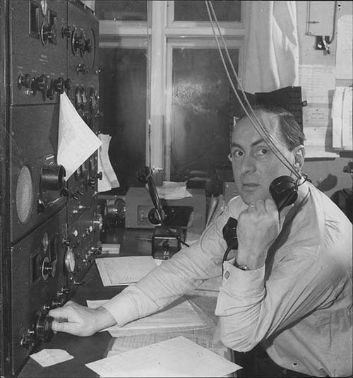
11. Thanks to Inland Marine Radio History Archive for the photo of WMI in 1937. Here is their website URL:   http://www.imradioha.org/WMI.htm


Appendix A  -  More Information on the Hammarlund Comet "Pro" Receiver


photo above: Ad for the Comet-Pro installed in a console cabinet. From "Radio News and the Short-Wave", March 1934. Note that the plug-in coils are mounted in a coil storage rack located under the lid on the left side of the cabinet. This is a later version of the Comet-Pro shown with AVC.


Comet and Comet "Pro" Features

Introduced in 1931, the first version of the Comet Pro was called the Comet "All Wave" Receiver. This version used 24A, 27, 35 and 47 type tubes. The power supply rectifier was a type 80. The IF frequency was 465KC and there were two stages of IF amplification. No RF amplifier was used so only two plug-in coils were used  for each tuning range. The plug-in coil set covered 250M to 16M in four pairs. A 240M to 550M AM BC band coil set was available rather early in production. Initially, the main tuning (WL and OSC) may have had the dials on the outside of the panel. Later they were fitted behind the front panel and viewed through cutouts in the panel. The Comet receivers were sold as a chassis or in a console cabinet. Later, a table cabinet was available that was a combination of wooden back and sides (painted black) with a metal lid and face plate, though some receivers were still sold as console "entertainment" radios. A change to the audio output tube came in 1932 with a type 27 taking the place of the type 47. Additionally, the field coil speaker connections were eliminated and an earphone jack installed with output terminals for a loud speaker with output transformer. When this version was used and, where thunderous volume was desired, a separate audio amplifier was provided. By 1932, the Oscillator Coil wiring was slightly changed and individual coil shields were added for both plug-in coils. Possibly at this time the Comet was renamed the Comet Pro.

In 1933, the entire receiver was given a complete upgrade and the new name, Comet-Pro, implied that the receiver was now "professional-quality" in both performance and design. The tubes were changed to type 57 and type 58 in the front end with electron-coupled oscillators used in the LO and BFO. The audio tube was changed to a 2A5 with an audio output transformer added with a 4K ohm Z output and a tapped output for earphone operation. The Wave Length coils were redesigned slightly for the new antenna input connections that allowed a dipole antenna with a balanced feedline to be used. The cabinet was changed to an all-metal fabrication, though the wooden version was still available on request, as was the console cabinet. A short time later, a Lamb-style crystal filter became an available option, followed by a 10 Meter coil set and by the end of 1933, Amplified AVC was added to the options. This required the addition of another tube, a 2B7 duplex diode-pentode for the AVC functions.

From 1934 through 1935 not too many changes are incorporated into the Comet-Pro since Hammarlund was primarily working on the Super-Pro receiver and supplying the Army with the SPA Super-Pro receiver. A "Stand by" switch function may have been added since some late Comet-Pros appear to have an extra toggle switch installed on the panel. Coil IDs were changed sometime between 1933 and 1934 with the engraved wooden handles changed to now use a recessed paper ID tag protected by a plastic cover. There were probably more late improvements to the Comet-Pro and I'll add to this description if more information surfaces.

Performance Expectations Using the Comet Pro

The 1933 and later Comet Pro receivers tune using separate OSC and WL condensers and a four section condenser in parallel with both the OSC and WL condensers that is used as a bandspread tuner. The power is turned on with the lower left knob which also is the Tone control. Since AVC was not optioned on my Comet Pro, the Sensitivity control (lower right knob) has to be adjusted for each station's particular strength because the audio gain is always at maximum and is not adjustable. BFO is tuned on with the toggle switch and the frequency control is the "swing arm" on top of the BFO coil can. The Crystal Filter has an "on-off" switch and a Phasing control. The design of the coils places the ham bands about in the center of each range, so setting the OSC and WL at "50" is a good place to start. The actual "peak" for the WL dial will somewhat depend on the antenna impedance but it should be fairly close to the OSC setting. The knobs nearest the arc scales control the OSC (left) and WL (right.) The bandspread (center larger knob) can then be tuned in search of signals. The Bandspread dial is illuminated and is projected onto a frosted window. All tuning scales are 0-100 and require "scale versus frequency" graphs to determine exactly where the receiver is tuned. The graphs were in the Hammarlund Comet Pro manuals. The Comet Pro has good sensitivity and the bandspread allows for easy tuning on all amateur bands covered. The 80 and 40 meter bands are especially well spread out with the 40M band covered by a little over 100% of the bandspread and 80M uses over 200%. Surprisingly, SSB signals demodulate quite well since we are using the Sensitivity control to set the volume. This provides the correct ratio of BFO injection to signal at the detector for good CW and SSB copy. CW signals are great on a Comet Pro. AM signals sound a bit different since there isn't any AVC. This results in the operator running the receiver with minimum front end amplification and maximum audio gain. This is great for noise reduction and QRM but full-bodied AM isn't really possible except on the AM BC band where signals are at a constant high level. High power ham AM signals also sound great but sometimes QSB (fading) will make enjoyment difficult as the Sensitivity control must be constantly adjusted for rapidly changing conditions. 

photo: The 1933 Hammarlund Comet Pro with Crystal Filter option but without the AVC option.

Images are not a problem with the coil sets DD, CC or BB but the highest frequency coil set AA (10MC to 20MC) is plagued with images. This isn't unexpected in a receiver without a TRF amplifier ahead of the mixer tuning above 10MC. With the AA set, it is best to use the graphs to set the desired frequency since the images are about the same strength as the tuned signal. The addition of an aftermarket pre-selector would all but eliminate the image problem on the AA range (see last photo in this section.) Drift is rapid for the first 10 minutes of operation, then settles down to a very slow drift that is standard for pre-war receivers. For a 1933 receiver, the Comet Pro is a fine performer and it would certainly be possible to use it for vintage ham communications today although earlier versions do not have a "stand-by" function.

Comet Pro Selling Prices

The Comet Pro list price was $150 without tubes. However, it was usually offered in several different configurations. Generally, prices were as follows:

A. Comet Pro Standard Chassis.......$79.38
B. Comet Pro Metal Cabinet..............$8.82
C. Comet Pro Crystal Filter option...$23.52
D. Comet Pro AVC option..............$17.64
E. Comet Pro tube set.......................$7.17 or $8.35 for AVC

With all options the price was usually around $140 in 1934. However, Leeds did offer a complete Comet-Pro for the total price of $117 FOB, in 1934. The 1934 competition's asking prices were as follows:

Patterson PR-10............. $70.00 - speaker included (dealer's price - list was $119)
Patterson Preselector.....~$25.00
National AGS-X............... $265.00 - price with all necessary accessories
National FB-7 complete...$90.00 - price with all necessary accessories
RME-9D......................... $112.00 - speaker included

photo left: The 1933 Comet Pro chassis. Antenna terminal is center of chassis. Speaker terminal is near the AC power cord exit.

Rebuilding Capacitors in the Comet-Pro Receiver: The Comet-Pro uses mostly metal box multi-capacitor packages along with two bath tub types and three paper wax type caps. The bath tub caps are black wax filled and have no metal bottoms so the wax is easy to "dig out" to remove the original cap and install a replacement inside the metal tub. The tub can be refilled for authenticity. The Aerovox paper wax caps have to have the rolled end "unrolled" and then the internal cap just slides out and a new cap can be installed and the end re-rolled. Cardboard circular end-covers go over the leads so when the new capacitor is installed the capacitor ends are not visible. A small amount of wax can be added for a more secure seal on the rolled end. The four multi-caps in metal housings are more difficult to rebuild. The housings are removed from the chassis and the wires disconnected from the circuit. Carefully unbend the flare on the eyelets that hold the bottom fiber cover to the can and remove it. Using a heat gun to get the can hot enough and using the wires to hold on to, pull the internal cap assembly out of the can. When hot, this pulls out easily. Make up a replacement cap of either three .1uf caps (four leads - three caps with one common) or the single .5uf with two leads. Use the original wire from the old caps and adhere to Hammarlund's color code in building the replacements. These can now be installed inside the cans and waxed in place. Reuse the eyelets to hold the fiber bottom to the can and be sure that the correct wires exit in the proper order out the holes. Crimp the eyelets and the cap is ready to remount and rewire. Be sure to note that the multi-cap that connects to the mixer tube is wired with the common connected to chassis and the other two multi-caps connect with their commons to the appropriate IF tube cathode. The multi-cap with the single .5uf connects to the detector tube. The Comet-Pro doesn't use very many capacitors when compared to the Super-Pro receivers and only the four multi-caps mounted in the square metal housings are time consuming to rebuild.

Comet-Pro filter capacitors are "wet electrolytics." Theoretically, they are self-healing and as long as they still have their liquid inside, they are still usable. The trouble is that the liquid can leak out, or it can dry out but most often the solids settle out and remain at the bottom of the can and the liquid no longer has the same dielectric properties. Though I have found a few wet electrolytics that seem to work okay, I usually replace them for reliability's sake. I mount new dry electrolytics inside the original can. This can be done many different ways depending on the tools available. First mark an index line on the can and then cut the bottom off about .25" up from the bottom. I drill a counter-sunk hole in the bottom piece of the can to install a 4-40 flat head screw that holds a solder lug inside the can. The center conductor is then tapped to hold a 4-40 screw and lug. The new electrolytic is installed between the two lugs. Use a piece of heavy paper rolled into a tube that just fits inside the upper can piece and the lower can piece. Epoxy the paper at the joint being sure to get the epoxy on both the paper and the inside of the can at the joint. Join the two pieces using the index mark as your guide for correct fit and hold in place with masking tape until the epoxy cures. Remove the tape, cover the joint with silver paint and then the rebuilt cap is ready to reinstall.

Henry Rogers - June 2008


photo above: The Comet-Pro with the PEAK P-11 Pre-selector. The P-11 adds two stages of RF amplification ahead of the mixer-oscillator of the Comet-Pro which greatly reduces images and adds a little gain in the sensitivity. The Comet-Pro becomes a splendid receiver for its design period when used with a separate RF pre-selector.


Appendix B - More Information on the HQ-120X and USN RBG Receivers

HQ-120X - Hammarlund realized that the Super-Pro was far too expensive for the majority of hams and that it was really a commercial-professional receiver that wasn't specifically for the ham market. So, Hammarlund designed and built a receiver that was intended just for the ham market, the 12 tube, HQ-120X, (introduced in Oct. 1938.)  To keep the selling price within the typical late-thirties ham's budget, the circuit uses a converter tube, single pre-selection, single-ended audio with 6 ohms output Z and a built-in power supply with voltage regulator tube. The frequency coverage was .54 to 31MC and ham band calibration was provided on the bandspread dial (generally credited as the first ham band calibrated bandspread available.) Selling price listed at $230 but the receiver usually sold for around $190 (usually much less) from most dealers. The HQ-120X was popular and provided decent performance on shortwave and ham bands up to about 18 Mc. Beyond that, images and lack of sensitivity become a problem (that would be on just the highest frequency band of the receiver - 18mc to 31mc.) Late in production, a special gray painted version was offered.

HQ-120X Circuit - Single conversion, single preselection superheterodyne tuning from .54 to 30mc in six tuning ranges. Tubes used are: RF-6S7, Conv-6K8, IF1-6S7, IF2-6S7, 1-6F6, Det/AVC-6H6, NL-6H6, BFO-6J7, S-Mtr Amp-6SF5, Audio Out - 6V6, VR-VR-150, Rect-5Z4.

Shown in the photo to the left is an unusual rack mount version of the HQ-120X. It has a special extended front panel and features side gussets with a full dust cover.

Navy Department-Bureau of Ships - RBG, RBG-1 and RBG-2

During WWII, the U.S. Navy had Hammarlund build them a special version of the HQ-120X receiver designated as the RBG/CHC-46140. The HQ-120 circuit was somewhat revised and the tube line-up was extensively changed (and reduced to 11 tubes,) the S-meter was replaced with a Super-Pro S-meter, capacitors were militarized, oil-filled units while the transformers and chokes were all hermetically-sealed (potted) units. The RBG was also physically larger than the HQ-120X with the overall depth of the receiver extended by about two inches. The ham band calibration bandspread was changed to Navy frequencies and the audio output impedance changed to 5000Z ohms. There was a matching loudspeaker designated as CHC-49154 (eight inch diameter speaker.) The RBG and the RBG-2 are virtually identical receivers with only minor changes to the S-meter style, some of the panel nomenclature and the size of the data labels. The RBG-1/CHC-46163 was for operation on 110vac 25 cycle power but was otherwise the same as the RBG.

RBG and RBG-2 Circuit - Band spread calibration is for the top four bands, so Band 3.2-5.7mc has BS cal'd 4.00-4.60mc, Band 5.7-10mc has BS cal'd 8.00-9.60mc, Band 10-18mc has BS cal'd 12.00-13.60mc and Band 18-31mc has BS cal'd 15.0-18.0mc. The square-flange bakelite S-meter of the HQ-120X was replaced with a metal case, Super-Pro S-meter. Tube types were upgraded to use all single-end tubes (except the converter tube, a 6K8) and the circuits were slightly redesigned which ended up reducing the total tube count to eleven. Audio output impedance was changed to 5000 ohms Z (it had been 6 ohms Z in HQ-120X.)

The "data plates" aren't actually removable tags. The data is embossed as part of the front panel nomenclature. The serial numbers are stamped into the panel. With the "militarization," the RBG-2 chassis is about 2" deeper than the HQ-120X had been.

Shown in the photo right is the RBG-2 serial number SN: 519. The RBG-2 versions have smaller data tags and different nomenclature on the Antenna Compensator. RBG-2 sn:519 is shown installed on the shock mount.

RBG-2 Repair or Rebuilding Tips - The iron used in the RBG receivers is from Chicago Transformer Company. These are all high-quality, potted-types of transformers and chokes. The resistors, on the other hand, are IRC brand and many of these have likely drifted in value over the past 75 years. Be sure to check the resistance values for tolerance (most were 10% components but 20% is acceptable.) I had to replace six resistors in SN: 519 and some of those had drifted 100% in tolerance. Six large, chassis mount, can-type capacitors are oil-filled paper dielectric types used as power supply filters. These are very reliable units and should only be replaced if they are leaking oil or are defective. Most of the bypass capacitors are multi-units in tubs. These are probably also oil filled and seem to be very reliable. The easiest way to verify these caps for leakage is to measure the voltage drop on the associated resistor. If excessive, likely the capacitor is the cause. I didn't find any defective in SN: 519. The 5K audio output impedance is high enough that any loudspeaker with a single-ended audio output transformer can be used. The LS-3 is suitable (8000Z) and I've used both National MCS-8 (7000Z) and Hallicrafters PM-23 (5000Z) with good results. If you use 'phones, the impedance is 600 Z ohms. SN: 519 had an inoperative crystal filter. The filter itself was found to be mis-wired internally. The crystal filter had been worked on sometime in the past and had likely not functioned since that time. The wiring problem was probably due to the types of wires used in the entire receiver chassis. All of the wire insulation is white with very small, various color tracers that can hardly be seen. Any troubleshooting involving tracing of the wiring should also be carefully rechecked against the schematic.   >>> >>>   Alignment is very easy but the LO high end is adjusted with compression trimmers so don't expect the alignment to stay put very long. Also, the inductor adjustments use a compression threaded spring washer to adjust the tension on the L adjuster. Many times these loosen when the L adjustment is made. Be sure to check these spring tension adjusters and tighten as needed (I found several had loosened.) The 18mc to 31mc band is fraught with images so be sure to keep the signal generator at the lowest possible input level to avoid mistaking an image for the proper frequency adjustment. Check the tracking from 18mc to 31mc. If you're aligned to an image the tracking will not be accurate. If the receiver tracks closely on the top band, you're aligned correctly on that band. Once RF tracking is aligned, the dial accuracy is very good. It was spec'd for 1% of the highest frequency on each band and it achieves this easily. Overall, the RBG-2 performs quite well up to about 18mc. It's an excellent receiver on 160M, 80M and 40M. 20M is also pretty good for sensitivity and lack of images. The top band (18-31mc) is limited in both sensitivity and image rejection. Using the RBG-2 at these frequencies would require a resonant antenna with some gain, like a yagi, or a preselector ahead of the receiver. Bandwidth is pretty narrow, I'd guess it's around 4kc at -3db down. The crystal filter works quite well at narrowing the bandwidth even more. Audio reproduction is fairly bassy due to the narrow bandwidth. If a wider bandwidth would be desired, then the IF section should be sweep aligned. Overall, a very nice receiver with great visual appeal for a vintage military radio station.
 
Henry Rogers - WA7YBS  © February 2008 - 2019  Additional Information Added: March 2008, April 2008, May 2008, June 2008, Aug 2008, Apr 2009, Nov 2009, Aug 2010 (clarification on model numbers,) Nov 2010 (add'l info on Geisler Mods), June 2012 - Re-Edit Style and Appearance to conform to later articles, October 2014 - corrections to Comet Pro info, July 2016 - SP-100LX info added, January 2017 - SPA info added, Apr 2019 - added info on SP-100LX restoration,   May 2019 - minor corrections and additions to all sections,  Aug 2019 - added Appendix C for HQ-120X/RBG information,  August 2019 - added SP-400 information, August 2019 - re-edited division of article into three parts for equal size of each part,  
 

Pre-War Super Pro Part 1                      Pre-War Super Pro Part 2                        Return to Home Index


Radio Boulevard
Western Historic Radio Museum

 Vintage Radio Communication Equipment Rebuilding & Restoration Articles,

 Vintage Radio History and WHRM Radio Photo Galleries

1909 - 1969

- 60 years of Radio Technology -


This website created and maintained by: Henry Rogers - Radio Boulevard, Western Historic Radio Museum © 1997/2023