Radio
Boulevard
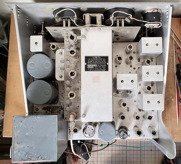
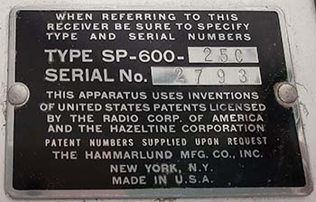
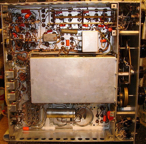
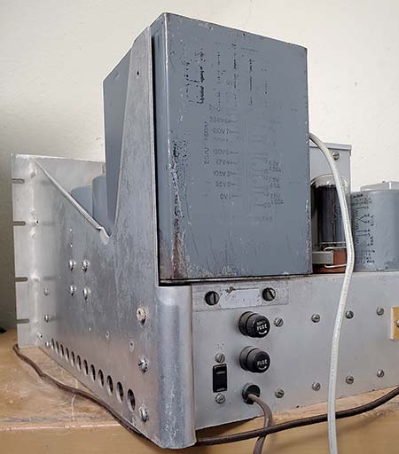
Hammarlund SP-600 Series of Receivers General Information about the SP-600, Circuit Details The Tubular Molded-Plastic Paper-Dielectric Capacitor Problem, Receiver Disassembly, Capacitor Replacement Electronic Rebuilding, Mechanical Restoration, Fixing the Chronic Dial Slippage Problem RF/IF Peak Alignments, New 2024 Sweep IF Alignment Procedure New 2024 Rebuild of SP-600 JX-21 SN: 21649, New 2024 Rebuild of SP-600-25C SN: 2793
Performance Expectations, No Receiver is
Perfect,
Collector's Photo Gallery
|
|
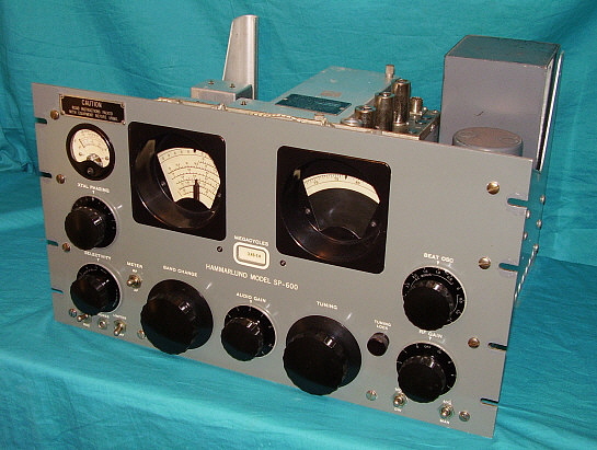
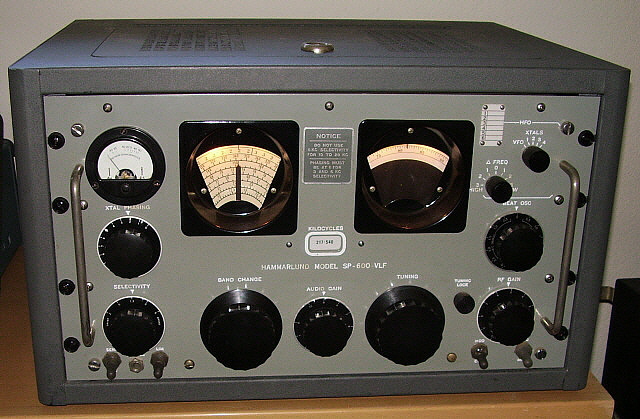
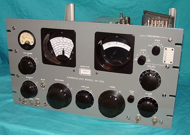
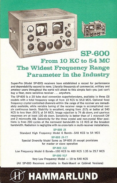
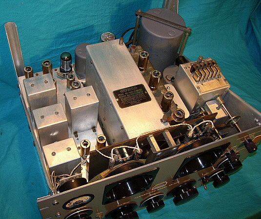
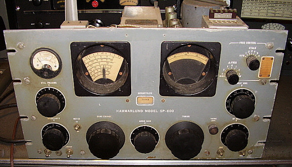
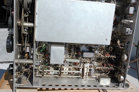
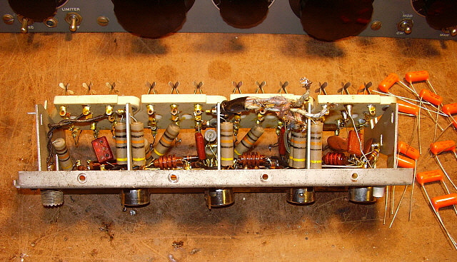
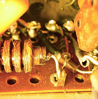
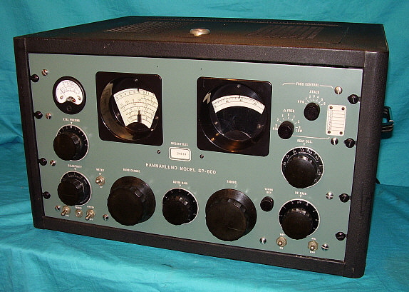
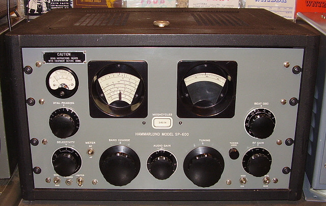
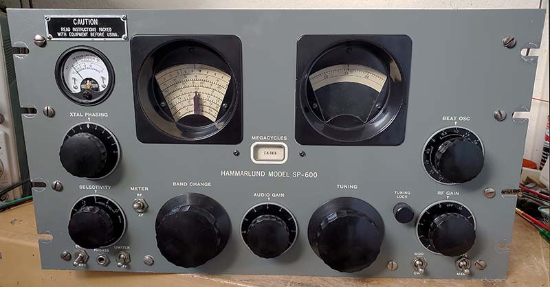
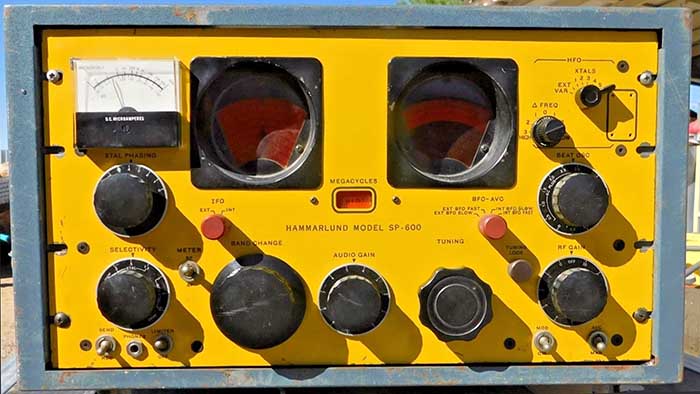
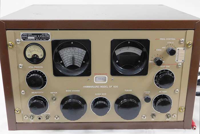
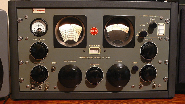
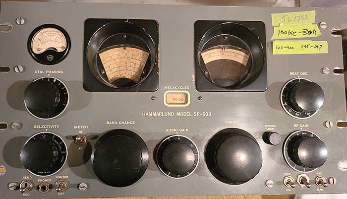
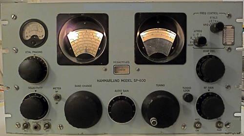
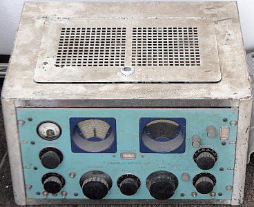
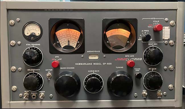
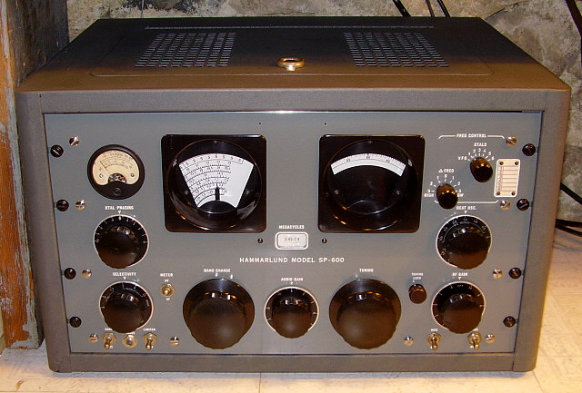
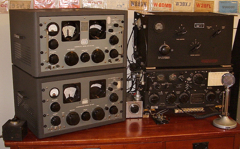
The Hammarlund SP-600 is certainly a longtime favorite of many vintage radio operators. With around 39 different versions produced from 1951 up to about 1972, one almost gets the impression that no two SP-600s are alike. With its massive proportions, super-smooth tuning and great performance, a SP-600 receiver sometimes assumes a prominent position in the ham station landscape. Unfortunately, all early production SP-600 receivers used leakage-prone molded tubular capacitors in the circuitry. It's common to find several burned resistors in the early SP-600 receivers due to the high leakage-current of the defective molded capacitors. For top-performance and reliability, these early receivers must be rebuilt. Unfortunately, over half of the fifty capacitors that need to be replaced are hidden in various assemblies within the receiver. These assemblies will have to be dismounted for access to the molded capacitors located inside. This web-article provides detailed information (with plenty of photographs) on the hidden capacitor locations, the rework necessary for the various assemblies and other important rebuilding information. Cosmetic and mechanical rework are also covered. I've now added detailed circuit descriptions to aid in the understanding of how the SP-600 functions, many new photographs have been added, a 2024 revisit to the workbench for a SP-600 JX-21 that also includes front panel repainting details. Another 2024 rebuild is included of an unusual SP-600-25C (no JX option.) To finish, I've added a newly written step-by-step procedure for performing a sweep IF alignment that's easy to follow and doesn't require special equipment (just a function generator with sweep and an oscilloscope with XvsY capability.) |
Hammarlund SP-600 Series of Receivers |
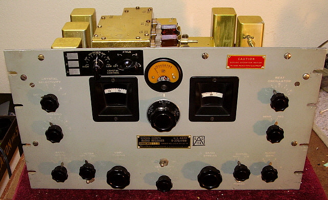
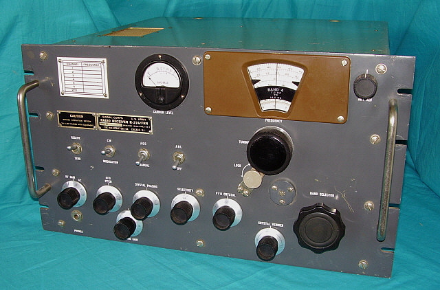
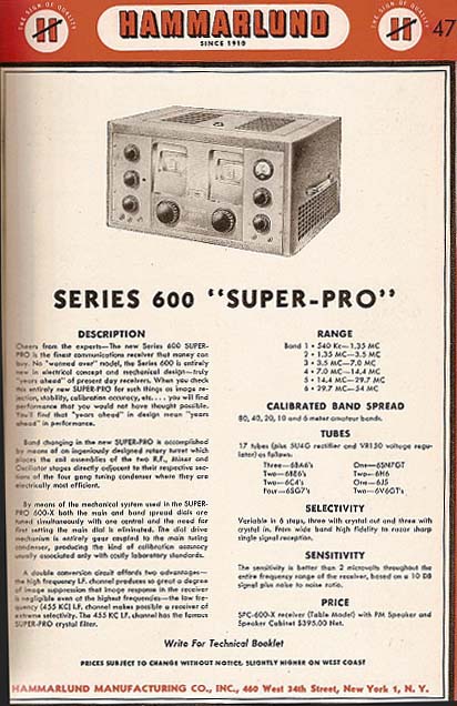
History of the SP-600 Hammarlund released an advertisement in 1948 that introduced their newest receiver, the SPC-600X. The receiver was to sell for $395 but, as Hammarlund had done before, this advertisement was really just to let hams and interested commercial users know what might be available in the future. No SPC-600X receivers were ever created other than maybe a prototype or two. Hammarlund had actually been working with the U.S. Army Signal Corps during WWII and post-WWII in an effort to provide a receiver that was stable enough for reliable RTTY communications. The new post-WWII receiver from Hammarlund, the SP-400, was just a re-packaged SP-200 with the same instabilities that had prevented its ability to perform at a level needed for military RTTY. The Signal Corps wasn't interested in the SP-400 and instead continued to work with Hammarlund (and other manufacturers) to design a receiver that had the performance requirements for RTTY. Hammarlund was well-known for their lethargic engineering pace and it was late-1950 before the first contract for the SP-600 receiver would be issued. But, even then, the actual production was delayed for another nine months. It was September, 1951 before the first Hammarlund SP-600 receiver was ready to be delivered. The new Hammarlund SP-600 was
primarily a military receiver. A few were sold to the commercial-users market.
Costing nearly $1000, it was priced out of reach for the average ham, even
though sometimes the SP-600 was advertised in QST. It was a very popular
receiver and many thousands were built, but nearly all receivers were
produced for
military contracts. It's known that much of the
SP-600 design criteria actually came from the U.S. Army Signal Corps,
especially the JX "Selectable Crystal Oscillator" concept and the turret band
switching. The "JX" Selectable Crystal Oscillator wasn't new for
the Super Pro receiver. The use of the selectable crystal oscillator is
seen on some "customized" BC-794 WWII Super Pro receivers and was even
designated as an "Improvement Kit" with the part number MC-531 from the
Signal Corps. Sometimes these receivers were "custom" rebuilds involving
various engineering companies for the Signal Corps. These "custom
rebuilt" BC-794 Super Pro receivers usually date from 1947 up into the
early 1950s and
were almost always for diversity RTTY or dual channel RTTY applications. |
|
|
SP-600 Circuit Details |
The Front End - The SP-600 is a 20-tube, double preselection,
dual conversion superheterodyne receiver that tunes from 540kc up to
54mc in six tuning ranges. The dual conversion is from 7.4mc up to 54mc.
Double preselection is used on all tuning ranges and consists of two
6BA6 tubes as cascaded TRF amplifiers. A 6BE6 tube is used for the first
mixer and a 6C4 is used for the HF Oscillator tube. The first mixer
stage actually uses a dual transformer (T1) that simultaneously converts
the incoming tuned signal and HFO for either a 455kc output or for a 3955kc
output. A switch is used to select either single conversion for Bands 1,
2 and 3 or dual conversion for Bands 4, 5 and 6. When using Bands 1, 2
or 3, the 455kc signal from T1 is routed to a Gate tube (6BA6) that then
connects to the 455kc IF amplifier circuitry. Another switch also
working on the Band Select operation disables the 3500kc crystal
oscillator to prevent the second
conversion from happening when Bands 1, 2 or 3 are selected. However, when Bands 4, 5 or 6 are selected, then the 3955kc
output from T1 is selected and routed to the Second Mixer (6BE6) where
it combines with the now enabled 3500kc crystal oscillator (6C4) producing a 455kc IF. The
Gate tube is disabled in dual conversion. The Selectable Crystal
Oscillator was the "JX" option the provided a method to substitute a
crystal-controlled HFO (6AC7) for the standard 6C4. This option was to
control frequency drift and to have a specific selected operating
frequency. However, the receiver still had to be manually tuned to the
approximate desired frequency for the RF and Mixer stages to be "in
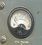
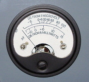
tune." The IF Section - The output of the Front End is first routed to the 455kc Crystal Filter. There are six selectivity positions 13kc, 8kc and 3kc bandwidths are non-crystal filter while 1.3kc, .5kc and .2kc are crystal filter positions. The Phasing control knob has a specific relationship to the position of the dual-stator/single rotor Phasing condenser and, with correct alignment, the 5 (<>) will provide maximum selectivity with heterodyne attenuation occurring around and near the <>. Two stages of tuned-input/tuned-output IF amplification are provided using 6BA6 tubes. The output of the IF amplifiers actually is routed to a Driver tube (6BA6) to increase the signal level even more before going to the Detector (6AL5 dual diode.) The second diode provides a separate AVC rectifier mainly for Diversity setups. The BFO is a permeability-tuned oscillator (6C4) and it uses a Buffer tube (6BA6) to isolate the BFO and allow for BFO injection level adjustments. The Audio Section - A dual triode 12AU7 provides the First AF amplifier and also provides an IF output cathode follower for a low impedance 455kc IF output of 70Z ohms. The audio output is a 6V6GT tube that provides 2 watts of audio power at less than 10% distortion. The audio output transformer uses dual 300Z windings that are connected in series for 600Z. The two 300Z windings were for some applications that required balanced outputs. There was also a third winding that was a low-level output for the PHONES jack. The Carrier Level meter worked either off of the AVC line in "RF" or it could measure "AF" level also using the RF-AF switch on the front panel. The AF to the meter was rectified with a 6AL5 tube that used the second diode as a Noise Limiter (clipper type.) |
The
Power Supply - The B+ rectifier is a 5R4G tube. The
filtering is a dual section type using two filter chokes and three
electrolytic capacitors. There's also a bias voltage rectifier that uses
a 6AL5 dual diode to provide -51vdc for the RF Gain control and using
resistive dividers also provides other bias voltage requirements. The B+
voltage also is applied to a 0A2 voltage regulator tube for a regulated
+150vdc that is used for the BFO, the HFO, the first Mixer and for the
Selectable Crystal Oscillator (the JX option.) NOTE: There are slight differences in most models. For instance, the SP-600-J4 only uses 19 tubes because it doesn't have the JX option but it also has a separate IF gain control for Diversity. The JLX covers 100kc to 400kc. The J-25 uses a 25 cycle power transformer and doesn't have the JX option (so 19 tubes, too,...and it was formerly the J-5 version.) There are about 39 different versions of the SP-600 with each version being somewhat different from the others. The proceeding description of the circuit covers the most often seen circuit. Specifications: Antenna Input Z - 95 ohms nominal Sensitivity - AM = 2uv, CW = 0.75uv with Signal to Noise Ratio of 10db Conversion Frequencies - 3955kc and 455kc, dual conversion from 7.4mc up to 54mc Crystals Used - 3500kc Conversion Crystal Oscillator and 455kc Crystal Filter Selectable IF Bandwidths - 13kc, 8kc, 3kc, 1.3kc, .5kc and .2kc (bandwidths at -6db) Audio Output Response - 85hz to 7500hz at -6db, 125hz to 4500hz at -3db (per graph) and flat from 200hz to 2500hz Audio Output Power - 2 watts at 10% distortion at maximum gain into a 600Z load AC Power Requirements - 8 taps on primary ranging from 95vac up to 260vac. 130 watts Weight - Chassis 65 pounds - installed in table cabinet, 92 pounds |
The Molded Capacitor Problem on Early SP-600 Receivers |
|
Why You Should Rebuild Your Early-version SP-600 Receiver - The Hammarlund SP-600 series of receivers were built for commercial-military users who required a receiver designed for continuous use with maximum performance capabilities. However, for the first SP-600s built, that was over 70 years ago! Nowadays, all SP-600 receivers built in the early fifties to the mid-fifties, that have not been rebuilt at sometime in the past, will certainly need all of the leakage-prone tubular molded-plastic, paper-dielectric capacitors replaced. The SP-600 receiver circuit seems to be able to keep on functioning even with many leaky capacitors ("leaky" refers to leakage current, how much current passes through a capacitor due to paper dielectric breakdown.) This has caused many operators to continue to use their SP-600 thinking everything is okay, BUT the receiver isn't working to specifications and sooner or later (likely sooner) there will be a failure that could cause serious damage to the receiver. On that note, the leaky capacitors not only cause performance issues but are also likely to cause failure of other components in the receiver circuit. It is quite common to find several burned resistors in any early SP-600 that hasn't been rebuilt but was operated long hours with leaky capacitors. The burned resistors are due to the excessive leakage current that the paper-dielectric capacitors develop after aging a decade or two. Two types of molded-plastic, paper-dielectric capacitors are found in early SP-600 receivers. Sprague manufactured the "Black Beauty" - a tubular black plastic encapsulated, color-coded, "paper" capacitor and Cornell-Dubilier supplied a tubular gray plastic encapsulated, color-coded, "paper" capacitor. Both types were used interchangeably by Hammarlund and both types exhibit high current leakage today (the C-D gray body, color code banded capacitor is perhaps worst capacitor ever built for developing leakage current - well, maybe Micamolds are slightly worse.) The paper-dielectric capacitors were only used in early production SP-600 receivers - from 1950 up to around 1955. After that, the infinitely more reliable ceramic dielectric disk capacitors were used. However, the largest production runs of SP-600 receivers date from 1950 up to about 1958 with somewhat smaller production runs until the early sixties. Thereafter, production levels were fairly low. Consequently, you're most likely to find an early production SP-600 unless you specifically look for the later versions (and they are usually the more expensive receivers.) The following sections cover all of the normal problems encountered when rebuilding the early SP-600 receivers. |
Some Preliminary Rebuilding Information |
Difficulty, Experience and Workmanship - Rebuilding a SP-600 receiver is daunting. But it is a project that is well within the capabilities of most communications receiver restorers. You will have to perform extensive disassembly of the receiver and some of its assemblies in order to access all of the parts that need to be replaced (and others that need testing.) To successfully complete a SP-600 rebuild you should be experienced with complete mechanical disassembly and reassembly of receivers. You must be able to perform quality component removal and installation with a high quality soldering technique using first-class soldering equipment and real SnPb solder. You must be able to keep track of your rework on several different kinds of assemblies. You should have experience in troubleshooting and aligning communications receivers using laboratory-quality test equipment. That being said, when performing the actual rework the most important thing to keep in mind is - don't be in a hurry and be thorough in your inspection and rework. Even for experienced technicians, rebuilding a SP-600 is time consuming and exacting work but hurrying through this kind of job will just lead to mistakes and shoddy workmanship. Rebuilding the RF Platform is tedious work and its band switching contacts can be easily damaged if that unit is not handled carefully while it is out of the receiver. All of the turret RF modules will have to be removed but this is easier than it sounds. Again, these small units can be damaged by careless handling - be careful. You'll have to make notes on the module removal since the manual doesn't have any instructions or drawings for correct reinstallation. Since the entire receiver is thoroughly disassembled to perform the rebuild a complete RF/IF alignment will be required. How well your rebuilt SP-600 operates will depend on your technical skills, your quality of workmanship, the type test equipment you use, the type of soldering equipment you use and your rebuilding experience. | Documentation Confusion - Though most SP-600 receivers look pretty much the same on the exterior, inside there are several differences between the many variations with different value components, additional parts or lack of parts being commonly encountered. The receivers shown in the photos in this write-up are two different versions of the early variety, both built with lots of molded tubular capacitors. The SP-600 JX-21 has the switchable crystal controlled oscillator and all of the modifications to incorporate the "JX" option. This is an early version (1953) JX-21, so it's somewhat different than the later 1956 USAF versions and completely different from the 1972 JX-21A version. The other receiver is the SP-600-25C. This receiver has the 25-60 cycle power transformer and lacks the switchable crystal-controlled oscillator. There are several minor differences between these two types of SP-600 receivers and certainly many differences with the other 39 or so variations of the SP-600. So, if your SP-600 doesn't exactly conform to what is stated here, don't be too surprised - I won't be either. |
Manuals and Schematics
- There are about 39 different
versions of the SP-600 but the receivers can be roughly divided
between early versions and later versions. This division is not based on
the number suffix but rather when the particular receiver was
manufactured. There aren't manuals for every single numbered version but
it's fairly easy to find a manual and schematic that's close for
your particular version.
Don't expect a lot of help from any of the Hammarlund-written manuals
that they called "Instructions." The SP-600 Instruction booklets are vague in many aspects for rework and testing. Many
important instructions are simply "left out" of the written material.
The wiring diagrams, the schematic, the voltage/resistance charts are
the most informative parts of the Instructions. As usual with Hammarlund,
the alignment section is brief, bordering on incomplete (at least the HF SP-600 alignment doesn't require lifting
resistors in the circuit like the SP-600-VLF alignment procedure calls
out.)
The Military came out with several different manuals for many of the variations, so it's possible to find both Signal Corps TMs (TM11-851) and several types of USAF manuals (mainly for the JX-17 and JX-21.) The military manuals will provide much more detailed information, especially in the circuit description areas and there are several sections that are for specific details, i.e., Parts Lists, Maintenance, Mechanical Drawings, etc. You'll find that a complete set of USAF military books will total over 200 pages and the Signal Corps TM11-851 is a lengthy 300 page book. However, with some of the military manuals, you'll find there are other, earlier manufactured versions of the receiver that won't be specifically covered in the manual. TM11-851 is from 1953 and covers the R-274A and R-274C along with the R-320 Diversity version (J-4 version.) This TM11-851 is the best information source for the early SP-600 receivers. The JX-17 and JX-21 USAF manuals are dated 1956 and they are good information sources for the later versions of the JX-17 and JX-21. The JX-21 was first built in early 1953, which means the 1956 USAF manual will have several slight differences from the early JX-21 receivers. This, of course, holds true if one was using TM11-851 (1953) for a later, 1956 USAF JX-21. In fact, it's true for almost all SP-600 receivers versus any of the available manuals. You'll always find slight differences in your receiver versus what's covered in any particular manual. It's more important to use a version of the manual that was issued closest to the date of manufacture of the receiver rather than going by the particular numerical "JX" version of the receiver (within reason, of course.) In other words, not all specifically numbered versions of the SP-600 were identically built. Essentially, the military manuals will have the most information but the Hammarlund Instructions booklets are useful for some information. You'll probably find it best to download copies of all of the manuals to find which best matches your receiver and provides sufficient information for rework. With the early versions of the schematic, as in Issue 1 and 2 of the Hammarlund Instructions booklet, no component values are on the schematic. You'll have to use the parts list as a cross-reference to determine the correct value of the component shown on the schematic. Later schematics, from Issue 3 up, do have the component values on the schematic. The "Instructions" booklets are good for quick references or general information and their small size make them good for reference when doing bench work. BAMA (Boat Anchor Manual Archive) has about four of the six issues of the Hammarlund "Instructions" online plus other SP-600 information. Generally, Hammarlund Issue 1 and 2 are for the earliest versions while Issue 3 is sort of a transition version. Issues 4, 5 and 6 are for the later versions. BAMA also has most of the military manuals, including TM11-851. It's best to down load all of the versions available to see which is closest to your particular SP-600. There are some dealers doing business on eBay that sell repro manuals if you are interested in having hard copies of the Air Force issues and of the Signal Corps TM11-851 (around 300 pages, so it's expensive - $45 plus shipping.) If your SP-600 was modified or has missing components you will absolutely need to use the manual, the schematic and the wiring diagrams that are correct for your receiver. Though it's possible to work through the SP-600 with general information from almost any manual, if the receiver has been compromised with modifications, you'll need the accurate wiring diagram and schematic to return the receiver to its original configuration. NOTE: As mentioned, don't expect a tremendous amount of information from any of the Hammarlund SP-600 "Instructions" booklets. Most of the written circuit descriptions are vague or incomplete. The alignment procedure is terse to the point of not even being complete. There aren't any detailed mechanical drawings. The sweep alignment instructions end abruptly after only describing a small portion of the procedure. The schematic, the wiring layouts and the voltage/resistance charts will help but most of the written information is as brief as possible and lacking details. The military manuals are much better and worth the expense to purchase if you plan on working on a lot of SP-600 receivers (or maybe working "in depth" on a "problem receiver.") However, even the mil-manual version of the sweep alignment consists of only two steps, so that particular type of IF alignment was considered "optional" therefore a "step-by-step" procedure wasn't included (it was assumed that the military radio technician working on the receiver knew how to do a sweep alignment and had the necessary test equipment.) However, I've added my newly written standard sweep alignment procedure for the HF SP-600 receiver that is a "step-by-step" guide that is a conventional type of sweep alignment with no special equipment needed. My procedure is further down this write-up in the RF-IF Alignment section. |
|
|
What Needs to be Taken Apart?
- Here is
the list of assemblies that need to be removed from the receiver in
order to gain access inside the assembly to
replace the problem capacitors. Quantities shown can vary depending on which
variation is being worked on. The quantity shown is for general
information - your receiver may be different. 1. RF Platform - 20 tubular molded-plastic paper-dielectric capacitors - all are .01uf - 400wvdc 2. Turret Bandswitch - 6 tubular molded-plastic paper-dielectric capacitors - all are .01uf - 400wvdc - only the 1RF, 2RF and Mixer modules for the .54-1.35mc band and the 1.35-3.45mc band have tubular molded-plastic capacitors that need to be replaced. 3. T-1 455kc/3.955mc Mixer Transformer - 1 tubular molded-plastic paper-dielectric capacitor. This unit is mounted to the side of the RF box next to the filter chokes. Inside the unit is one .01uf - 400wvdc paper dielectric capacitor. 4. 3.500mc Crystal Conversion Oscillator - 3 tubular molded-plastic paper-dielectric capacitors. This unit is mounted under the chassis. All capacitors inside are .022uf - 400wvdc. 5. IF Transformers - 2 tubular molded-plastic paper-dielectric capacitors inside the Conversion IF transformer, value is .022uf - 400wvdc. 1 tubular molded-plastic paper-dielectric capacitor inside two of the 455kc IF transformers, value is .022uf - 400wvdc. The Crystal Filter/IF transformer doesn't have paper-dielectric capacitors inside. 6. Switchable Crystal-Controlled HF Oscillator Assembly ("X" Option) - 2 tubular molded-plastic paper-dielectric capacitors inside this unit. Both are .01uf - 400wvdc. Additionally, most receivers will have two tub units that are double .05uf at 600wvdc capacitors. There is also a .05uf tubular and a .25uf tubular (Sprague built these units usually) that are mounted on standoffs on the inside-front apron of the chassis. These capacitors are also paper dielectric types and should be replaced. The usual procedure is to replace these with individual components when doing the rebuild. All of the other under-the-chassis tubular molded-plastic paper-dielectric capacitors are easy to access and replace. All total, the amount of tubular molded-plastic paper-dielectric capacitors that need to be replaced will exceed 50. Components - When Hammarlund eliminated the tubular molded-plastic "paper" capacitors from production they went to ceramic disk capacitors. Ceramic disk capacitors as new replacements for the paper dielectric caps would be excellent but be sure the new ceramic disks chosen have a voltage rating equal to or higher than the original "paper" capacitors. SBE Orange Drop (usually polypropylene dielectric) or even metalized film "Yellow-Jacket" types (usually polystyrene dielectric) are also excellent replacement capacitors. The choice is not critical since any of these types of capacitors are at least a 1000 times better than the original paper-dielectric capacitors. |
Where to Start? - It might be a good idea to first get the receiver somewhat operational before starting disassembly. This will assure you that you won't encounter any really serious problems after you have gone through all of the work entailing the rebuild. Usually, you'll end up replacing a couple of capacitors and maybe a burned resistor to get the SP-600 running enough that you can check out all of the control functions to make sure the receiver is basically functional. Common sense should guide you in deciding whether or not to get the receiver entirely operational before starting the rework. When you are satisfied that nothing is seriously amiss with the receiver, you can begin disassembly which will require removing the front panel, the side panels, the tuning condenser cover and the bottom cover on the band switching turret. You can also remove the shield covers on all of the IF transformers, the shield cover on the Mixer transformer T-1 and the shield cover on the 3.5mc Crystal Conversion Oscillator. Everything will then be accessible for capacitor replacement and thoroughly checking all of the receiver circuitry. |
Rebuilding the SP-600 Assemblies |
The RF Platform This is the most difficult assembly to remove, rebuild and then re-install. The bandswitch must be placed in a position exactly in-between any of the "lock-in" band select positions. This allows the short contact pins from the RF units in the turret to not be engaged into the contact fingers of the RF Platform. Remove the top cover over the tuning condenser and unsolder ALL of the connections to the tuning condenser. There are 16 connections that need to be de-soldered here. Then remove the top cover from T-1 and unsolder the wires that are connected to the terminals there. There are from five to seven wires that need to be unsoldered depending on which version is being worked on. Next remove the four mounting screws on the top of the RF Platform. Now, carefully lift the RF Platform up while guiding the T-1 wire cable as they pass through the opening to T-1. With the RF Platform out of the receiver, you'll be able to see 20 molded caps that need to be replaced. Be sure to watch the alignment holes versus the placement of the new capacitors. You want to have clearance from the alignment holes down through the holes in the ceramic mounts and down to the adjustments on the RF units of the turret. Make sure your placement of the new capacitors doesn't block alignment tool access. Try to mount the new capacitors in exactly the same position and same orientation as the originals. Check the contact fingers for corrosion and clean with De-Oxit applied with a Q-tip - nothing abrasive. Don't move the bandswitch control on the receiver until you have reinstalled the RF Platform. Re-installation requires that the wire cable be guided through the access hole to T-1 as you lower the RF Platform into place. Reconnect the wires to the T-1 terminal board and reconnect all 16 connections to the tuning condenser. Replace the mounting screws. Check for proper operation of the bandswitch-turret and smooth engagement of the contact pins of the turret into the RF Platform contacts. |
|
|
More on the RF Platform Rebuild
- Often times you will
find that the RF Platform was not carefully handled during a repair job that
was performed in the past. Reference the photo to the left and note that the
second
contact finger in the front row is broken. This is the 1RF section
and the Antenna Input connects to this contact finger. This is an old
break and was discovered when I removed the RF Platform from the SP-600
JX-21 receiver during its rebuild. This particular receiver showed
evidence that it had been worked on many times during the past by a
technicians that were careless in their workmanship. The fact that the
contact finger was left unrepaired seems to support this opinion.
Repairing this broken contact finger is possible because only five
contact fingers are used in the HF Oscillator, Mixer and 2RF sections but that Hammarlund made all of the
ceramic mounts the same - with six contact fingers. The Mixer and the
2RF sections use the extra contact finger as a tie point for components but the
HFO section will have one unused contact finger present. It is possible
to remove the unused contact finger from the HFO section and then reinstall it to replace this broken one in the
1RF section. The 1RF section on bands 1 and 2 is the only place where
all six contact fingers are used. Removing the contact finger requires careful workmanship. You must use solder wick and remove absolutely all of the solder from the contact finger lugs. Next, insert an 18ga. wire into the "T" slot in the ceramic and push gently down on the tang that holds the contact finger in the ceramic. Once the tang is down, that side of the contact finger can be pushed slightly up. Insert the 18ga. wire in the other "T" slot and push down on that tang, then that side can be pushed slightly up. Once the two tangs are released the contact finger can be removed from the top of the ceramic mount. These contact fingers are very fragile and will break easily, so go slowly and carefully, then successful extraction is fairly easy. To install the good contact finger just push it into place in the slots and the tangs will lock. Then solder the bottom lugs to further lock in place. One can also note from the close-up photo to the left that there is some corrosion on the fingers and also a lot of dirt or "tuner grease." This should all be cleaned with denatured alcohol and a Q-tip. Stubborn areas may require a brass brush to remove the corrosion. When everything is clean then go over the contact fingers with De-Oxit which contains a corrosion cleaner along with a lubricant that works fine for these kind of contacts. Careful, meticulous rework to the RF Platform is essential to regain the superior performance that the SP-600 is capable of. |
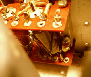
A Thorough Inspection of the RF Platform Reveals
More Problems - It is
possible that some of the "leaky" original capacitors in the RF Platform
circuit will have compromised some of the associated resistors in the
circuit. Thoroughly inspect the RF Platform carefully for burned
resistors and measure each of the resistor values just to be sure. As an
illustration of just what might be found, note the photo to the right.
This is the RF Platform from the SP-600-25C receiver. Note that R-15 is
burned. This is a 510 ohm resistor that now measures 30 ohms due to the
overheating that took place when in operation with the "leaky" original
capacitor, C-43. It can been seen in the photo that the
green-brown-brown color code has changed due to the heat - especially
the second digit designator band which now appears flat, pale tan rather
than brown. This suspicious appearance prompted physical measurement of
the resistor value which showed that the value had changed from 510 ohms
down to 30 ohms. Naturally, this resistor will have to be replaced along
with all of the original tubular capacitors.
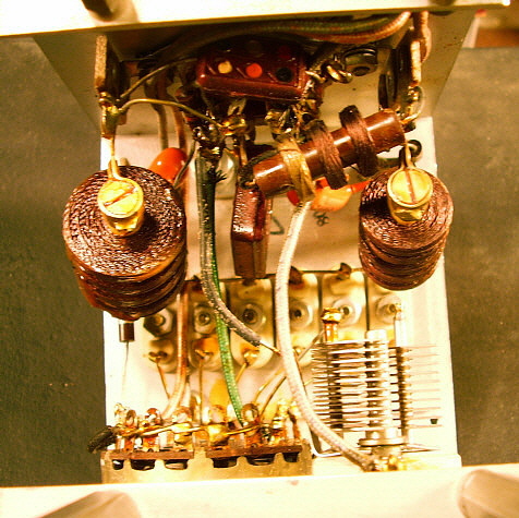
Another interesting observation is that R-16 is missing from the circuit. This 1K ohm resistor is the plate load for the 2RF amplifier. Looking at the photograph to the right, R-16 should be connected to the terminal to the rear that R-15 is also connected to. It can be seen that no resistor is mounted there. During the initial check out of the receiver, operation appeared normal (for an original condition receiver.) So one can conclude that even though the 2RF amplifier was not operating to its full capabilities, it did pass enough of the signal through that stage that the defect was not noticed in the initial operation check out. This shows that a thorough physical inspection of the RF Platform is necessary to find all of the defects that might be present. The Connection Diagram for the "Tuning Unit" (RF Platform) is extremely helpful for the inspection. IMPORTANT NOTE: Steve Zarco W6SSP has rebuilt six SP-600 receivers. Two out of the six had tuned frequency instability that Steve traced to the mica capacitor in the 1st Mixer. This capacitor is located in the RF Platform and replacing it after you've rebuilt and reinstalled the RF Platform means removing the RF Platform AGAIN! Steve says that after the first two receivers, he now replaces all of the mica capacitors in the RF Platform as part of the rebuild. Something to think about because nobody should have to pull the RF Platform from the same receiver more than once. |
|
|
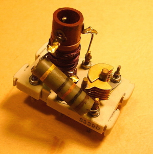
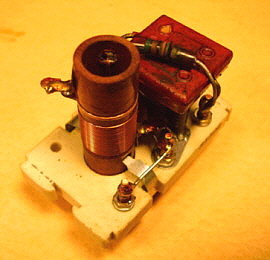
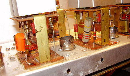
The Bandswitching Turret This is a really great piece of engineering. As the bandswitch control on the front panel is turned, the turret rotates and places into an engagement position the contact pins of four front-end modules that make up the 1RF, 2RF, Mixer and LO sections of the front-end for each tuning range of the receiver. Each front-end module is built onto a ceramic mount that has the tunable coil, the trimmer capacitor and a couple of resistors and fixed capacitors that make up each circuit. The connections are to short pins on the back of the ceramic mount that engage the RF Platform fingers when the turret is rotated into position. Each front-end module can easily be removed from the turret since they are only held in their mounted position by two arched clips. The was a special tool for removing these clips (6R4625-3) shown in TM11-851. I've never come across one. Fortunately, the clips are easy to remove and install with needle-nose pliers. Grasp the clip with the needle-nose from the straight side behind the tab the goes through the hole. Lift up with the needle-nose and this will "roll" the tab out of the hole. Install the clip in the reverse manner. After you've done this once or twice, it becomes really easy to remove or install the clips. Six of the RF modules use molded capacitors that will need to be replaced. All of the others have mica caps installed. The .54mc-1.35mc section will require replacement of a capacitor in the 1RF, 2RF and Mixer modules and the same units require a capacitor replacement in the 1.35mc-3.45mc band. Each module has one molded capacitor of .01uf at 400wvdc. While you are working on the turret, it's a good idea to check the resistors along with the other components installed in all of the front-end modules. The Mixer sections especially seem to sometimes have burned resistors but they do turn up in the other modules also. Once and a while you'll find someone has inadvertently injected high level RF into the receiver antenna input and burned the 1RF coil. Check the pins of each RF units for corrosion and cleanliness. Don't use anything abrasive unless corrosion is present, then you might have to use a brass brush and denatured alcohol to clean. Don't scrub with the brass brush because the pins are silver plated (silver oxide is conductive but there's usually other contaminates that need to be removed.) Just gentle brushing to remove what comes off easily. Follow with De-Oxit applied with a Q-tip. Be sure to check the tightness on all of the tensioners that are on the inductance adjustments. These are circular metal disks with slots along the edge that are threaded onto the inductance threaded shaft. These tensioners provide a spring load on the inductance adjustment so it will stay set. Sometimes these tensioners loosen and when that happens you'll find that the inductance adjustments don't seem to hold adjustment when doing your alignment. Check them - they should be a little more than snug but not over-tight. Too tight and you'll have difficulty adjusting the inductance with the alignment tool. The tensioner should be just tight enough to hold its position and not move when the inductance shaft is adjusted. NOTE: Early modules will have different value resistors compared to later ones. |
|
More on the Front-end RF Modules - It's probably a good idea to remove each one of the modules to closely check it over. Though you can look through between the modules and see most of the components, you can't see everything. As an example, look at the 2RF module for the 3.45mc to 7.4mc band shown in the photo to the right. The resistor is burned in two. It isn't really visible when the module is in place and by looking between the modules. It was found because each module was removed for close inspection. Besides the resistors, you also should look at the trimmer capacitor and check for bent plates and check the mica capacitors for cracks or other problems. The burned resistors are always caused by leaky molded capacitors located in the RF Platform. Many times a rebuilder will recap the RF Platform and the six modules that have molded caps but not check each of the RF modules for damage. The end result is missing problems such as the one shown to the right. It pays to be thorough. |
|
The IF Transformers There are molded capacitors located in each of the IF transformers with the exception of T-3, the Crystal Filter/IF transformer assembly. IF transformers T4 and T5 have one .022uf 400wvdc molded capacitor inside that will need to be replaced. T-2 has two .022uf 400wvdc molded capacitors inside that will need to be replaced. The IF transformer shields are held in place by four 6-32 screws that mount the shield to the chassis by way of right angle brackets on the shields. Removing the screws and the shield allows you access inside of the IF transformer. There is a blade spring that provides a load on the IF adjustment screws. Be sure to keep track of the spring and replace it when you re-install the shield. The molded capacitors are very easy to replace in all of the IF transformers. Be sure to check the value of the carbon resistors that are located inside the IF transformer shields since any leaky capacitors may have compromised the resistor value. NOTE: Be aware that the IF transformers change slightly in the later versions of the SP-600 and will have slightly different connections to the terminals under the chassis. |
|
|
T-1 455kc and 3.955mc Mixer Transformer This is the small assembly that is mounted on the right side of the RF tuning box near the power supply filter chokes. It is held to the RF box by six screws that are difficult to access in the non-"X" receivers because of their proximity to the power supply filter chokes and impossible to access in the receivers with the "X" option. In "X" optioned receivers, the Crystal Controlled Oscillator unit has to be removed first. Unsolder the four wires that connect to the Filter Capacitor/Filter Choke mounting assembly, remove the four screws and dismount the assembly. You don't have to unsolder the wires that connect to the Crystal Controlled Oscillator unless you are going to remove it for rebuilt, then unsolder them. Unscrew the fours screws that mount the Crystal Controlled Oscillator and move it out of the way (or remove it for rebuild if you've unsoldered the wires.) Now you should have easy access to T-1. On non-"X" receivers all you have to do is remove the mounting screws from the nearest filter choke and move it back and to the side to allow the cover of T-1 to be removed. Once the cover of T-1 can be removed, then you can access the single .01uf 400wvdc molded capacitor located inside. After replacement of the capacitor, the cover can be re-installed. If you are not going to rebuild the Crystal Controlled Oscillator then remount it (but if you have rebuilt it then resolder those wires) and then remount the filter choke-capacitor assembly and resolder those wires. The 3.500mc Crystal Oscillator This assembly is located under the chassis. The shield is mounted to the chassis using four 6-32 screws. Removing the screws and the shield allows access to the 3.500mc oscillator circuit. There is a vertically mounted fiber board that has some components mounted to it. There are three .022uf 400wvdc molded capacitors used in this circuit that will need to be replaced. When re-installing the shield note that there are three notches that allow the circuit wiring to pass under the shield when mounted without pinching. Be sure the wires pass through the notches. Also note that there is a notched fiber spacer that sets on top of the vertical fiber board. This must be in place when re-installing the shield since it prevents vibration movement of the vertical board that might mechanically affect the 3.500mc crystal. |
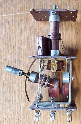
The Selectable Crystal Oscillator ("X" option) This unit allows the operator of an "X" optioned SP-600 receiver to substitute a crystal HFO for the regular HFO for increased stability (reducing or eliminating frequency drift.) Six crystal sockets allowed the user to install HC-6 crystals for fixed frequency operation. A six position switch allowed selecting any of the crystals installed. There is also an ON-OFF function (labeled "VFO") that routes the B+ from the standard HFO to the JX oscillator. A vernier frequency control was also provided. The VFO/crystal channel switch and the frequency vernier were brought out as two extra controls added to the upper right section of the front panel. When selecting a crystal frequency to be used in the Selectable Crystal Oscillator, only the HFO is changed - you will still manually have to tune the receiver to the selected operating frequency in order to have the RF and Mixer stages also tuned correctly. You'll need to install the correct frequency HC-6 crystal which is not the same frequency that you want to tune in. The manuals will provide the formula to calculate the crystal frequency required for the desired receive frequency. Basically, 455kc or 3.955mc is added to the desired receive frequency to obtain the correct crystal frequency depending on the band and whether the receiver is operating single or double conversion. Also, on the higher frequency bands the result is divided by 3 or 4 for operation on the crystal frequency harmonic. Removing the Selectable Crystal Oscillator unit requires removing the knobs and any shaft couplers. Remove the filter choke/filter capacitor sub-chassis to access the wiring harness connections. Five wires have to be unsoldered there. There is also a connection to the switch and the RF Platform to unsolder. Remove the screws from under the chassis that mount the hex stand-offs that are attached to the bottom of the unit. You should now be able to extract the entire unit from the receiver. Several screws need to be removed (and the sheet metal cover sides slightly bent outwards to remove it) in order to gain access to the Selectable Crystal Oscillator. Once inside you'll find two molded capacitors that need to be replaced. Check the resistors for drift and clean the switch to complete the rebuild. Re-assemble and re-install in the reverse order. Once the Selectable Crystal Oscillator unit back in the receiver and is operational, it's doubtful this particular option will ever be used unless you want to listen on one frequency with no frequency drift. When the SP-600 is running on its own HFO it doesn't drift noticeably after a 30 minute warm-up, so only the most demanding frequency-stable military data-type (RTTY usually) requirements would benefit from using the Selectable Crystal Oscillator. |
|
Completion of the Electronic Rework |
Under the
Chassis - There are still more molded capacitors
located under the chassis but they are easy to see and most are easily
accessed for replacement. There are usually a couple of "bath-tub" dual
capacitors that have two .05uf 600wvdc capacitors internally mounted.
It's easiest to just replace these with individual "Orange Drop"
capacitors. These "bath-tubs" are PCB oil-filled and present possible
health issues when rebuilding is attempted. It's best to just replace
these dual .05uf "bath-tub" capacitors with modern types.
Sometimes the .05uf dual capacitors were used for the AC line filter but dual .01uf capacitors were also used on some later receivers. Also, there are two black (sometimes silver) tubular capacitors mounted against the front of the chassis on stand-offs. These are .25uf for the AVC delay in CW mode and .05uf for the Noise Filter circuit. These can be replaced with appropriate "Orange Drop" capacitors. |
Resistors - It's a good idea to check ALL of the resistors and replace as necessary. It's common to find a few, if not several, burned resistors in an un-rebuilt SP-600. The molded capacitors have been leaky for decades and any operation of the receiver for extended periods of time will end up overheating many of the resistors. The leaky capacitors have caused the resistor failures - there is nothing wrong with the original resistor wattage ratings. I have actually found 2W resistors installed in place of burned 1/2W resistors while the "leaky" molded capacitor that caused the original problem was left in the circuit. The receiver, when operating correctly, is designed to work with the specified resistors and there is no need to "out think" the radio engineer by installing higher rated parts. |
Rebuilding the Electrolytic Capacitors - The SP-600 uses
a triple 20uf electrolytic B+ filter capacitor with a built-in resistor
connected between the negative terminal and the capacitor's metal case.
The way in which this electrolytic capacitor is physically mounted and
electrically connected, with the capacitor's common negative
connected to chassis, seems to eliminate the need for this particular internal
component (it isn't shown on the schematics either.) These were
extremely high quality electrolytic capacitors and many are still fully
functional today. If you want to use the originals, then check them
carefully for leakage and then reform them if the receiver has not been
powered up for several years. Also, most SP-600 receivers have several
10uf electrolytic capacitors that are mounted in "bath-tub" containers.
Again, these were very high quality units and many are fully functional
BUT check them carefully. If you feel uncomfortable using 70 year
old electrolytic capacitors (and maybe you should,) just replace them. I
usually install the new electrolytics inside the original housings since
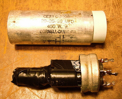
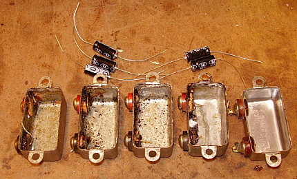
it results in a much better under-chassis appearance. The B+ filter capacitor rebuild involves cutting the can of this triple 20uf electrolytic to remove the old capacitors inside. Mark the can before cutting to assure it goes back together in alignment. Cut slightly above the base crimp. Once the cap is in two pieces use a heat gun to get the black tar hot enough that the old insides just slide out of the can. The same treatment will remove any black tar in the bottom piece that has the bakelite terminal base. Wear heavy gloves when using the heat gun. Once the can is cleaned out you can install three new 22uf 450wvdc capacitors with the negative leads tied together. You will have to stack the caps as seen in the photo to the right for everything to fit into the can. Use sleeving to insulate the leads and electrician's tape to hold the three caps in alignment. You'll have to drill four small holes (.060") in the bakelite base of the capacitor near the terminal posts to allow the new capacitor's leads to be connected to the proper terminals. You'll notice that the terminals that are on the inside would make great connections but unfortunately they are made out of aluminum and can't be soldered to. Don't drill through the aluminum as it is so soft it will clog the drill flutes and break the drill bit - drill through the bakelite. Wrap the new capacitor's leads around the proper terminals and solder. Now you'll have to join the top of the can back to the base. Use some paper card stock to act as a backing for the epoxy that is used to glue the can back together. Coat both sides of the card stock with lots of epoxy and fit the top back in place making sure that the marks on the can are in alignment. Wipe the excess epoxy off the outside of the can. Wrap the can with masking tape to hold the two pieces in alignment until the epoxy sets up. Paint the glue joint with silver paint to hide the seam. This isn't a perfect, undetectable rebuild of the B+ filter cap but it makes the installation of new electrolytics much neater. The tub mount 10uf electrolytics do not use PCB oil but are filled with the old black tar so rebuilding is easy. An old style, really large, high wattage soldering iron with the huge 3/4" inch wide size tip is required. These old behemoths transfer enough heat to remove the bottom plate by melting the solder and prying up the bottom plate, one side at a time. Once the plate is off, dig out the tar and the old capacitor and replace with a new electrolytic as shown in the lower photo right. It's not necessary to replace the bottom plate. This process is next to impossible without using a very large soldering iron. If you don't have one, just replace the old tubs with new electrolyics installed on new tie strips for the bias supply and at the existing tie point for the driver tube and at the 6V6 tube socket for its cathode by-pass. |
|
Wiring Harness and Soldering - Be sure to check over the condition of the wiring insulation under the chassis. The wire insulation on early SP-600 receivers is rubber-like and covered with cloth. It seems that the cloth, which probably has fiberglass strands in it, is prone to fraying and disintegrating depending on the amount of rework and the storage conditions that the receiver has gone through in the past. Later SP-600s use wire that doesn't have the fiberglass strands and is more like standard hook-up wire. Also, check all of the soldering rework that was done in the past. The quality of the rework can vary dramatically from receiver to receiver. Resolder any suspicious looking joints. Sometimes you will even have to strip and tin new leads on the wires that have had too much stress and breakage during the past reworks. | Tubes & Tube Shields - It's obvious that all of the vacuum tubes need to be tested and replaced as necessary. Weak or marginal tubes will compromise any receiver's performance capabilities. However, don't rely entirely on the tube tester. Proper operation of the receiver is the final test for the tubes. Although uncommon, you may find tubes that test fine in the tube tester that are noisy or might have problems that only show up after 10 or 15 minutes of operation. Clean all tube sockets with De-Oxit as you re-install the tubes. The HFO tube, a 6C4, has a special tube shield that has a grounding extension that is connected to the front ground binding post terminal on the top of the tuning condenser shield. The other tube shields are standard nickel plated types made by various manufacturers. The heat-conducting black IERC type tube shields can be fitted to the SP-600 tubes and they do lower the tube temperature which results in longer tube life. Many SP-600 receivers were fitted with the IERC tube shields during their active use with military and commercial users but, nowadays, the expense of a complete set of IERC tube shields is something to consider since the receivers typically aren't operated 24/7 anymore. The Hammarlund manuals always show the old nickel plated, high heat-retaining types of tube shields because they were the original type supplied with the receiver. |
|
BFO Repairs
on the "JX" Versions - The BFO usually doesn't
have any serious problems but if anything does develop, getting into the
BFO can is a real headache if the receiver has the "JX" option. Of
course, the time to thoroughly check out the BFO is when the receiver is
disassembled for the rebuild. But if a problem develops afterward,
you'll find it's impossible to easily access the BFO coils and circuitry
inside the can because the Selectable Crystal Controlled Oscillator has
a switch shaft that is directly over the BFO can. Even if you remove the
shaft and the coupler, you still can't get the BFO can off. To gain access to the BFO
coils and other internal components for repairs first remove the side panel of
the receiver. Next, under the chassis, unsolder the four wires that
connect to the filter capacitor and filter chokes. Now, remove the
screws that hold the filter choke platform to the chassis standoffs and
remove the entire assembly, chokes included. Now, remove the four screws that thread into the
standoffs that mount the Crystal Controlled Oscillator (CCO) and remove
the nut from the diagonal brace. Now the CCO can be moved
back out of the way. It isn't necessary to unsolder any of the wiring to
the CCO. You can now remove the BFO can and
proceed with any repairs. When the BFO repairs are complete, then
reassemble the receiver enough to allow power up and testing. If the BFO
functions correctly then complete reassembly.
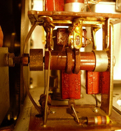
Shown in the photo to the left is the BFO from the JX-21 receiver. I had noticed that the BFO wouldn't hold alignment and many times when turning the BFO knob, the BFO frequency wouldn't change. As can be seen in the photo, the metal end cap that has the threaded rod passing through it had become detached from the coil form. This allowed the blade spring which provides an end load on the slug adjustment to become fully extended. This resulted in erratic movement of the slug and BFO frequency. The repair was to reattach the end cap using epoxy making sure that the end cap was fully seated onto the coil form and held in place while the epoxy cured. On "non-X" optioned receivers, working on the BFO is easy only requiring removal of the side panel for good access and visibility. Then removing the BFO can to observe, repair and test. |
Major
Modifications - The SP-600 was an expensive receiver that
was normally used either by the military or by commercial users. It's
performance is legendary. It isn't usually found with extensive
modifications installed. However, most SP-600 receivers have gone from
former owners that didn't usually install undocumented modifications to
new owners - hams. Some hams still seem convinced they can
"out-engineer" the Hammarlund engineers. Extensive ham modifications almost never function better than the
original circuit that was designed by a team of professional radio
engineers (and, in the SP-600's case, by the Signal Corps.) Almost all ham "major" modifications are poorly installed.
Almost all ham modifications tend to enhance one area of performance at
the expense of performance in another area. Additionally, ham
modifications are rarely documented so their design intent and expected
improvement is usually a mystery.
I always try to return the receiver circuitry to the original design and layout. I always try to use components that are the same values and ratings as the original. It is acceptable to replace a 10% resistor with a 5% - but not vise versa. Replacing the molded capacitors is the exception and, when replacing the molded caps, be sure to use all the same type of new capacitors - it looks like a professional rework job then. I have found through restoring many communications receivers that the original design works best and many functional anomalies can be avoided by adhering to the original component type, original placement and original wiring layout. Once the receiver is returned to original, now all of the original documentation - no matter where it comes from - can be used and will be accurate for all future users of the receiver. Additionally, the manual's operational instructions will be accurate and the receiver will perform as described in the manual. |
Major Audio
Modifications - The Argument Against 'em - The audio
output on the SP-600 is communications-grade audio. The audio response
graph in the manuals generally shows that the SP-600 audio was 125hz at
-3db for a low and 4500hz at -3db for the high. Since there are no audio
compensation controls, the typical loudspeaker seems to reproduce the
audio with a noticeable lack of bass
response. Just how much this absence of bass response bothers the user
is certainly subjective but Hammarlund engineers had good reasons for
the original audio response shaping. The SP-600 was designed as a
communications receiver and as such it must perform that function
equally well in all modes of reception. While it might be pleasing to
listen to an AM BC station with a bass response that goes subterranean,
this type of response is a hindrance to good CW copy. Additionally, RTTY
and other data modes are adversely affected with an audio response that
over-emphasizes the bass. Certainly SSB communication was developing
while the SP-600 was in production and, while the demodulation of a SSB
signal was probably not a major consideration during the design stages,
SSB intelligibility is certainly better without significant bass
enhancement. The SP-600 owner should be aware that AM reception was just
one of many communication modes that the Hammarlund engineers and the
Signal Corps had to
consider while designing the receiver. Although I don't really think it's necessary, a minor reshaping of the audio can be accomplished. If just a few minor changes are installed it usually won't limit the SP-600's ability to demodulate CW and SSB signals. Paralleling the two 5100pf coupling capacitors in the audio section with .01uf capacitors then paralleling the audio output tube's cathode bypass with a 10uf electrolytic and adding a 10uf electrolytic in parallel with the 1st AF Amplifier's 1K cathode resistor will give the audio output a response that sounds like a typical, older communications receiver. This simple approach will satisfy most users that feel that the original 125hz at -3db limited the bass too much and these few minor changes don't affect the ability of the SP-600 to function normally in the CW and SSB modes. I think that the 600Z ohm output transformer also affects the bass response because a matching transformer is necessary when using a typical 4Z ohm or 8Z ohm loudspeaker. A high quality matching transformer will help. Also, a good quality loudspeaker and enclosure would help. Also, the loudspeaker should be placed several feet away from the operating position as the distance will reduce the level of perceived audio highs and enhance the audio bass response. If your version of the SP-600 has the Diode Load terminals on the rear chassis, a shielded cable can be connected to the "diode jumper" and the shield connected to chassis. This can be routed to a high fidelity amplifier "sound system" and that will definitely help the audio quality. You'll lose the Noise Limiter (no great loss) and a 600 ohm resistor should be connected across the 600 ohm audio output terminals but the audio results should be impressive. |
Cosmetic Restoration of the SP-600 |
Dismounting the Front
Panel
- The front panel of the SP-600 has several captive shafts that are used
for the BFO control, SELECTIVITY control, XTAL PHASING control and the
JX FREQ XTAL control. The easiest method for removal of these captive
shafts is to loosen the set screws on the flexible coupler behind the
panel. These are easy to access if you have a fairly long Allen wrench.
Also, the knobs for BAND CHANGE and TUNING have to be removed. Also, the RF and AF GAIN knobs,
the JX VFO knob and the TUNING LOCK knob have to be dismounted. The TUNING LOCK
itself has to be loosened before trying to remove the front panel. The
remaining knobs don't have to be removed since their captive shafts are mounted
to the panel. All five of the toggle switch nuts need to be removed. The control
mounting nuts for the RF and AF GAIN pots and the PHONEs jack need to be
removed. The connections to the Carrier Level meter have to been dismounted. Now
the 10 mounting screws can be removed, four on each side and two at the bottom
of the panel. At this point the front panel can be pulled forward and it should
come off easily.
Next, the individual captive shafts need to be dismounted. The knobs usually don't need to be removed since just the captive bushing nut on the backside of the panel can be removed. Keep track of which captive shafts go where since they are slightly different. The BFO shaft has the rotation stop pin, for example. In others, the shaft may be slightly longer or shorter. Since the knobs can be left mounted, that will identify the captive shafts. Dismount the CL meter. Dismount the Tuning Lock mechanism. Dismount the two dial escutcheons. Dismount the plexiglass from the backside of the panel that covers the band indicator. The front panel is now stripped of all parts and can either be cleaned and polished or it can be prepped for painting. If you want to preserve the original paint then cleaning can be done with dish soap and water or any other sort of mild cleaner. Avoid using Windex because it has ammonia as its active cleaner which can remove some kinds of paint used for panel nomenclature. Glass Plus which is ammonia free can be used. Grease or oil film can be removed using WD-40 as a solvent followed by Glass Plus to removed the WD-40 residue. Most panels will have some chipping that can be touched up using matched paint. The panel can then be lightly polished or waxed if desired since the original paint is super tough. Removing the original paint is difficult but repainting isn't too complicated since only the front of the panel is painted. The edges are also painted but the entire backside of the panel is left bare aluminum. |
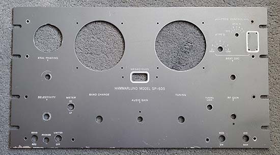
Repainting the Front Panel
- This should only be done if the panel is really in poor
shape or if you want to change the color from the original gray. First, if
you want to maintain originality, have the front panel paint matched at
an automotive paint shop. This way you end up with high quality paint
that's the correct color. Many automotive paint stores will fill spray
cans with the matched paint for a nominal fee. This makes painting the
panel much easier. One spray can is usually more than enough paint to do a
single front panel about three or four times. You probably will have to
spray the panel at least twice since usually the first try will have too
much paint applied. Even if you're changing the original panel color, go
with an automotive paint for the best quality. The original paint is very, very tough and will require a couple (at least) applications of heavy-duty methylene-chloride epoxy stripper (this type of stripper usually isn't available anymore, in 2024, so use any type of epoxy stripper that's available and hope for the best.) After stripping, make sure the panel is super clean and degreased before painting. Avoid sanding or brushing with a steel brush because originally the panel was chemically etched so a paint primer wasn't necessary. Since you're going to have to fill the engraving after the panel is painted you don't want to have anything that's going to add more paint than is necessary. Spray a couple of coats and see how the engraving looks. If it's still pretty sharply defined and the panel coverage looks good then stop. Too much paint will fill the engraving and prevent proper nomenclature filling. Two coats should be the maximum. Most off the shelf "rattle can" paints do have "fillers" in the paint to act as primers to fill scratches. These "fillers" aren't used in automotive spray paint. Also, the automotive paint will "shrink" somewhat as it is drying. At first, while the paint is not fully dry, the nomenclature will look like there is too much paint applied but wait at least one day and see how the paint looks after it has fully dried. It should shrink and the engraved nomenclature should then look sharply defined. Wait at least two days before doing the nomenclature fill. This gives the new paint a change to cure and harden. |
Nomenclature Fill - For the nomenclature fill, I mix Artists Acrylics of White, Raw Sienna and just a "touch" of Black to end up with a Manila color. "Pure white" will look way, way too bright. Do only one or two sets of engraving at a time. Apply the paint with a brush into the engraving and you don't have to be real careful - just paint it in. Let the paint set for about one minute. Then use a small piece of paper towel folded a couple of times that has been dampened (not dripping wet) with Glass Plus. Don't use Windex - only Glass Plus works for removing the excess fill paint without damaging the panel paint. This will probably take two Glass Plus wipes to get all of the excess paint off of the panel. Most likely some of the engraving fill will also be removed. Redoing the fill a couple of times is normal and this results in the best looking engraving fill. I always have several pieces of towel ready because you'll need at least two pieces for each set of engraving to remove the excess paint. Let the paint in the engraved area set for a few minutes more the second time and then wipe the area down again with another dampened paper towel to fully clean the area. Once the engraved fill has set for about 10 minutes, then the engraved area can be carefully wiped with a flat dry paper towel to make sure the engraved area is dry. Let the fill paint dry for a day. Finally, if more a gloss is desired, then use carnauba wax and apply a nice polish to the panel. It will look great. |
Chassis Cleaning with Easy-Off Oven Cleaner - SP-600
receivers were normally used in controlled environments during their
active lives. However, most of the receivers have now become victims of
poor storage in humid areas such as garages, basements or worse - sheds.
The moisture damage to the aluminum usually shows up as oxidation and
dullness to the finish or, worst case, pits. This kind of damage can be
somewhat removed by using Sodium Hydroxide. A convenient way to apply
Sodium Hydroxide is with Easy-Off Oven Cleaner (EOOC.) Spray a small amount of EOOC into a cup and using an acid brush or Q-Tip, apply a coating to the chassis. EOOC does react with aluminum but you aren't going to leave it on the surface for more than just a few minutes. Wipe off the EOOC and then swamp the area with water using either a brush or Q-Tip. Gently wipe and repeat the water rinse a few times to neutralize the EOOC. Application of the EOOC should be performed in a well-ventilated area. The surface aluminum will be left very clean AND will have the flat finish of the original aluminum. This treatment leaves the aluminum very clean but doesn't "polish" or scratch to remove the oxides and dirt. >>> |
>>> Nobody wants a "polished to a mirror" finish on a receiver
chassis. Most restorers want the aluminum chassis to appear as it did
when the receiver was fairly new. The EOOC treatment ends up with the
aluminum looking "flat" original. The IF transformer shields and all of
the the other removable aluminum pieces including the side gussets can
be taken outside and, one at a time, sprayed with EOOC, left for three
minutes and then rinsed with water from a hose. This ends up with the
aluminum pieces looking very clean and with a flat finish like they had
when they were new. Be sure to rinse all the pieces thoroughly with
water. Also, don't rub the aluminum pieces with anything - just let them
air dry. Rubbing will actually end up slightly polishing the aluminum
piece and will ruin the flat finish you are trying to achieve. When
cleaning the IF, BFO & T-1 shields, be careful of the lettering on top
of the cans. The lettering is very delicate and almost any cleaner seems
to destroy it. Avoiding the lettering works best. This EOOC trick only
works well on aluminum. It doesn't have too much of an effect on steel -
it cleans (as it's supposed to clean your oven) but that's all. Components like the power transformer and the chokes can be cleaned with any mild cleaner then touched-up as necessary. |
Tuning, Logging
and Band Indicator Dials - There are three dials on the
SP-600, the main tuning dial, the logging dial and the small band
indicator dial. The paint on these looks durable but it's common to find
the paint cracked and flaking off. Also, staining from excessive
moisture encountered during poor storage conditions is common. You'll
have to test a small area of the dial paint to see how well it is
adhering to the dial base. I use a small paint brush and gently brush
the area and look to see if I see flaking. This is a sign that the dial
paint is beginning to crack due to surface corrosion on the dial base.
If you don't see any residue coming off with gentle brushing then the
dial paint is in good shape and can be cleaned very gently with a damp
cotton cloth. Some dials will be found with the paint already falling
off and with surface corrosion apparent in the areas missing paint. It appears that the original method used to finish the dials was to chemically apply a black oxide coating to the dial. This might have been black anodizing but it could also just be an oxide treatment. Next, the white paint was applied into the areas that are to be the background color. This had to be a relatively slow drying paint that was allowed to settle leaving the high points - the dial numerals - slightly above the paint. Then a squeegee type of device skimmed the high points to reveal the black oxide underneath. I haven't tried this method of dial restoration since spare original dials are so expensive and I don't want to take a chance on ruining a decent set of dials. However, I do now have a spare set of SP-600 dials that are in poor condition and sometime in the future maybe I'll attempt this type of restoration. For the time being though, the only accepted solution for poor condition dials is a photo paper overlay that is glued to the back of the dials and then reverse mounting the dials. These never look original and are only a "stop-gap" solution until good condition original dials are found or someone develops a good restoration method for the SP-600 dials. And on that note,...over the years since I wrote about restoring SP-600 dials, I've come across many, many good condition original dials. They're pretty easy to find. Keep an eye on eBay as they turn up there often. Also, cheap SP-600 parts sets at ham swaps often have decent dials under the dirt. With just a little searching of the Internet, it's easy to find good condition original SP-600 dial sets for sale. |
Dial Pointers - The dial pointers have a black oxide finish on them. Sometimes they have scratches but touch up is easy with a black marker pen, like a "Sharpie," which gives the sort of "transparent" look that the original finish had. The main tuning dial pointer can be removed with two small screws while the upper pointers can be removed by dismounting the dial lamp assemblies. NOTE: Black Sharpies are actually dark purple. Try other makes of black markers. I've found many other types that are really black and not purple. | Escutcheons and Plexiglass Screws - The escutcheons seem to take a lot of hits and are usually scratched up. Repainting is sometimes necessary but usually they will touch up fine and look more original that way. I use satin black spray paint that is sprayed into a small cup and then applied with a very small brush. The satin black seems to blend better than gloss, even though the escutcheons are somewhat glossy. If you've repainted the front panel, you'll probably want to repaint the escutcheons, too. Be sure to use high quality automotive paint as this will give the absolute best results for your repaint. The screws that hold the plexiglass dial covers always seem to be rusty. Just wire brush and paint with flat black paint. Don't torque these screws tight or you'll crack the plexiglass. Just barely snug is all that is needed. If you make new plastic dial covers, be sure to use Lexan as the material,...it won't crack and is scratch resistant. Lexan is easily available as garage door window replacements at Home Depot. |
Meter Before |
Meter After |
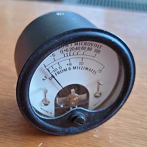
RF/AF Level Meter - The RF/AF Level Meter on the early SP-600 uses a paper scale that is very prone to moisture damage since the meter itself is not a sealed unit. If the scale is really stained badly, it can be removed and covered with a reproduction meter scale. You can make your own repro scale if you can scan the stained original scale into a computer. Disassemble the meter and remove the scale. Scan the scale into the computer. Use a "photo editor" program to correct the defects. Sometimes the discoloration is too severe to easily remove in the photo editor. In that case you can try making successively lighter copies (on a copy machine) of the scale until the nomenclature remains but the color background is even. Then scan that copy into the computer and photo edit out any remaining defects. Size it correctly and make the final print out on photo paper that is non-gloss finish. I specify photo paper for a fine texture finish and clean printing. The final scale copy has to be lightly glued over the original scale backing. When the meter is reassembled make sure the needle doesn't drag on the new scale since it is now a little thicker. Also, clean the needle stops of corrosion (common problem.) When the entire meter is together it is very difficult to tell that the meter scale is not original - except that it looks a lot better than most originals do. The later Marion Electric meters are a much higher quality and use a paint-on-metal meter scale. If you keep an eye on eBay these later heavy-duty metal housing meters do show up occasionally. |
|
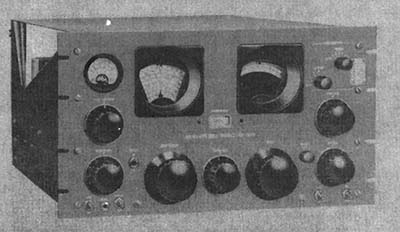
Rack Mount Dust Cover - The dust covers are almost always missing from the rack mount SP-600 receivers. It looks like the cover itself was a flat aluminum piece with no bends and was probably at least .060" thickness. It's possible that a very shallow bend is present at the front and rear of the top cover and these bends can't be seen in the artwork. The bent edges front and back would help prevent the top cover from bending itself if something heavy was set on top of the cover. The dust cover had right angle tabs mounted at each corner. These tabs pointed down and when the dust cover was in place the tapped hole in each tab aligned with holes in the rear pylons and in the front-top of each side panel. The Signal Corps TM11-851 has several artwork type drawings showing the dust cover installed. From these drawings one can see how the tabs looked and how they apparently were riveted to the dust cover. Since the dust cover is simply a flat aluminum piece and the right-angle tabs would be easy to make, replicating a SP-600 dust cover would be fairly easy. See header picture at the beginning of this write-up as this is artwork from TM11-851. The picture to the right is from the USAF manual for the JX-21. |
|
Cabinets -
Most SP-600s were rack mounted, usually in
multiple receiver set-ups. Originally, the SP-600 could be ordered as a
"table mounted" receiver with cabinet. The table mounted receivers did
not have bottom covers since the cabinet provided the same function. It
was possible to order a conversion kit to convert a table receiver to a
rack mount. Although it is mentioned in the manual, it seems likely that
someone could have ordered a cabinet from Hammarlund to convert a rack
mount to a table mount. Since most receivers were in racks, there are
more receivers around than original Hammarlund table cabinets and this
has resulted in the original cabinets becoming fairly high priced. Since
the SP-600 has a very deep chassis only a few types of non-Hammarlund
cabinets are deep enough to house the receiver. The original cabinets do
not have threaded holes for mounting the panel of the receiver to the
cabinet. Instead, a drilled and tapped metal strap fits behind the panel
mounting flange and then the panel screws thread into the strap. There
are also a couple of holes in the bottom of the cabinet to allow
securing the back of the chassis using the tapped mounting brackets that
originally hold the bottom panel on.
Cabinets are usually wrinkle finished and can be found in several different shades of gray but the original paint was a slightly brownish-gray color. The cabinets can be cleaned with Glass Plus and a soft brass brush, like a suede brush. Soak each surface in turn with the Glass Plus and then work the brass brush gently in a circular motion to work the dirt and grime out of the wrinkle convolutions. Wipe the area with a paper towel and repeat until the paper towel wipes are fairly clean. Don't scrub too long as the paper towels will never be perfectly clean and after a few times scrubbing you are really seeing some "dead" paint as color on the towels. Usually two applications is enough. Let the cabinet dry thoroughly and then do any touch-up that is necessary and let that dry. Finally, apply 10W Machine Oil to a clean cotton cloth and wipe the cabinet down. Then wipe off the excess oil with a dry cotton cloth. The cabinet will look beautiful. |
Changing the Cabinet Paint Color
- This can be accomplished very easily. The easiest process is to use an
Artist's Acrylic paint that has been mixed to the desired color. Have a
sponge and some water in a shallow dish. Have the mixed paint on a piece
of cardboard. You'll need quite a bit of paint for this process. Apply
one side at a time for better control of the paint application. Put some
paint in the dish with the water and mix. It should be a fairly thin
mixture, like milk. Now, use the sponge to apply the paint onto the
cabinet. Just keep adding more of the thinned paint with the sponge
until the coverage looks even and the color is what is desired. Move to
the next side and repeat the process. Add more paint to the water as
necessary. Keep doing this until all sides have been covered (both
inside and outside the cabinet,...and the bottom.) Let the cabinet paint
dry overnight. The paint will have a slight sheen but not a gloss. If it
looks thin and not covering the original paint, then repeat the process.
The second coat will cover for sure. This method of painting is very
easy, doesn't smell and looks okay. Good enough if the receiver is going
to have other equipment piled around and on top. A complete repaint is difficult. You can sand the original paint for prep and try wrinkle finish painting but it's very difficult to achieve even coverage and even wrinkling over such a large area and with multiple sides involved. It's possible to do a light over-spray using a satin or matte finish spray paint. Be careful as this usually looks much worse than expected. It's okay if the color sprayed is close to original but requires a bit of care if it's a "color change." Of course, the final method (and probably the best for such a large cabinet) would be to take the cabinet to a professional powder coating business. Nowadays, there are several types of wrinkle finishes that powder coaters can apply. Their black wrinkle finish is difficult to distinguish from original. Grays are somewhat problematic and depends on what the powder-coater has for paint when it comes to matching the original gray. I've only seen excellent black wrinkle from powder-coaters but this is always changing as more and more paints become available. |
Mechanical Restoration Work |
Body and Panel Work - Many SP-600 receivers have been roughly handled during the last few decades of moving and storage. Consequently, you might find bent panels, chassis or broken parts in general. Most of the straightening of panels is common sense and routine. It normally involves removing the bent part and using either auto body techniques or using a non-marring hammer to straighten them. The front panel is heat-treated aluminum and, if bent, is more difficult to straighten than would be expected. Still,...it will "straighten." | Install ALL of the Screws - The SP-600 uses a lot of screws to mount various shields, panels and other assemblies. All of these screws are important for mechanical stability and for shield electrical connections. It is very common to find an SP-600 missing many of the screws for these parts. Most "hamsters" think that only two screws are required to mount panels (one screw, if it's really tight!) ALL of the screws are necessary for the receiver to have its mechanical strength and stability, so be sure to install all of the screws and replace any that are missing. |
Tuning Mechanism
and Chronic Dial Slippage - The SP-600 tuning works by
friction only. There are gears to rotate the tuning condenser but the
main drive system is entirely by friction of brass-on-brass wheels.
There is a load spring in the shape of an "S" that provides enough
pressure to ensure good frictional drive. Essentially, the tuning knob
shaft rotates a drive wheel that in turn drives an idler wheel that is
grooved. The logging dial rim makes contact with the idler wheel's
groove and that rotates the logging dial which then via it's hub drives
the rest of the tuning gear system. Everything depends on good contact,
clean surfaces, proper loading and that the metal surfaces are not
"polished" by wear. It's common to find the tuning mechanism dirty and many times this is what is causing the tuning slippage. Remove the front panel along with the main tuning dial, the logging dial and the band indicator dial. Spray the brass gears with WD-40 and work the dirt out with an acid brush. WD-40 is cheap and a good de-greaser. Dry any WD-40 residue with paper towels. When clean and dry, lubricate only the bronze bearings - sparingly, they are oil-impregnated but a drop or two of 10W machine oil will help since most of them are pushing 70 years old. The brass gears really don't need lubrication and too much oil or grease on the gear teeth are just "dust traps" that end up causing wear and other problems. Be sure to clean the rim of the logging dial with denatured alcohol. Sometimes you'll find the the rim of the logging dial has a thin film of grease on it. This will cause slippage when tuning. The rim of the logging dial must be super-clean. Additionally, the rim-surface of the logging dial must be "perfect." In other words, the can't be any dents, warps, gouges on the rim. In addition to a visual inspection, be sure to run your finger tip along the rim to see if you feel any imperfections. Any rim issues need to be corrected by lightly using a very fine file to dress down the imperfection so the surface is even and smooth. When dressing down the imperfections be sure to maintain the proper shape of the dial rim and don't remove any material other than the defects. Clean the rim afterwards with denatured alcohol. The contact areas where the drive wheel engages the reduction wheel and the groove where it engages the logging dial rim must be super clean. Clean all of these brass wheels thoroughly with denatured alcohol. Again, check these mating surfaces for imperfections and correct any that are found. Usually the drive wheels are in good condition but it depends on the condition of the receiver and how it was stored. Reinstall all three dials. Inspect the logging dial and how it fits into the drive wheel groove. Check the tuning action. It should be super-smooth. Once in a while, after cleaning, there might still be some tuning slippage. At this point, you might suspect the "S" tensioning spring that loads the drive wheel against the rim of the logging dial. The "S" spring sometimes looses its "springiness" but you can remove the "S" spring and bend it outwards to increase the loading then re-install it. Sometimes the "S" spring has just "had it" and it needs to be replaced with a new one (or a good one from a parts set.) Most of the time the "S" spring is okay and other problems are causing the slippage. The FIX that WORKS - If you've tried everything,...thoroughly cleaning, checking the logging dial rim, readjusting the "S" spring and the dial still slips,...then the problem is likely excessive polish on the surface of the logging dial rim due to wear. If the slipping is still present, then apply a solution of rosin and denatured alcohol (about the viscosity of water) into the groove of the drive wheel using a small paint brush. You don't need much, just brush a little of the rosin-mix into the groove. Rotate the dial using the tuning knob to transfer the rosin solution on to the dial rim and then let the solution dry (alcohol evaporates.) The "grip" of the rosin will assure that the dial will not slip anymore. If in the future the rosin seems to loose its grip, just reapply the rosin-mix to the drive wheel groove and tune the receiver to transfer the rosin to the dial rim. Easy. If you have trouble finding rosin powder, try using a rosin block that's for a violin bow. Just use a small file and file a small amount of the bow rosin into a cup. Add a little denatured alcohol and stir until the rosin is dissolved in the alcohol. The viscosity of water is about right. If you don't know anyone that plays a string instrument, then try buying a rosin block at a musical instrument store. When everything is "right" with the tuning mechanism its operation is better than "velvet smooth" and there will be no slipping of the dial drive. |
The
Antenna Input Twin-ax Connector -
Most of the SP-600 receivers were equipped with a UG-103/U twin-ax
Antenna Input connector mounted on top of the RF Platform. The mating
connector, the PL-102 (identified as UG-102 in the SP-600 manuals,) is
not something that every ham had lying around in their junk box.
Consequently, many SP-600s have had their UG-103/U replaced with a
standard (read - "easy to find") SO-239 UHF type coax connector. The
original SP-600 design concept was to use RG-22 balanced coax (twin-ax)
for dipole antennas and since this was 95 ohm Z line, the match was
fairly close. Nowadays, few (if any) hams run twin-ax because the losses
are so high. So, if you are going to utilize your ham station
transmitting antenna for the receiver antenna, you'll end up with
standard unbalanced coax running to the SP-600. You'll have to ground
one of the twin pins in the PL-102 connector for proper unbalanced
operation. It doesn't matter which pin is grounded, just so one of them
is. This can be done by soldering a wire from the coax shield up to one
of the twin pins. I don't advocate replacing an original UG-103/U
connector but, if it's already replaced, once the mating coax connector
is hooked up, you can't really tell if an SO-239 has been substituted
for the original twin-ax connector. Additionally, the right angle UHF
adapters are a lot easier to find than the twin-ax right angle adapter,
the UG-104/U. If you use small diameter coax, like RG-58 or RG-8X, you
don't really need the right angle adapter since the coax is flexible
enough to make the bend to allow it to exit out the "antenna hole" in
the original cabinet. If you are rack mounted or without a cabinet then
there will be no problem with the antenna coax at all. NOTE: UG-103/U versus SO-239: I received an e-mail from Hammarlund SP-600 historian Les Locklear that provided information that Hammarlund approved the substitution of a SO-239 for the UG-103/U in a revision sheet dated September 13, 1951. SO-239 receptacles appear on receivers as early as the SP-600 JX-8 versions. The conclusion is that it's possible to find a SP-600 with a SO-239 antenna receptacle that is correct and is an approved end-user installation. |
|
IF/RF Alignment of the SP-600 |
The SP-600 JX alignment procedure in the "Instructions" booklet reads like Hammarlund expected the receivers to only be worked on by professional-level or military technicians. Although there's sufficient information to perform a standard peak alignment, the IF sweep alignment instructions stop abruptly after just a few sentences about the second Mixer adjustment. Most SP-600 receivers were "peak aligned," BUT, what if you want to sweep align the IF? Do you absolutely need that special piece of equipment called out in the military manual procedure? The answer is,...of course not. The SP-600 is a standard dual conversion superhet and its IF can be sweep aligned with standard equipment. A sweep generator will be necessary. Many Function Generators provide a sweep mode that can easily be used. An oscilloscope with XvsY capability is also required. I've provided a complete procedure for sweep aligning the IF of a SP-600 receiver. When completed you should find that the receiver now remains at the same gain level as a wide AM-BC signal is tuned across. No more amplitude peaks and valleys when tuning across a wide signal. When switching from 3kc to 8kc to 13kc, the IF passband stays centered and the gain remains at the same level. As to why the original Hammarlund alignment instructions are so vague and incomplete? Well, if you think the SP-600 alignment procedure is bad, you should take a look at the "impossible to perform" alignment procedure for the SP-600-VLF. |
Peak Aligning the IF
Section - The IF is straight forward in alignment except
for the second conversion frequency adjustment of 3.955mc. This requires
the 455kc IF to have been very accurately aligned first. Then the dual conversion
3.995mc signal from the first mixer combines with the 3.500mc crystal
oscillator signal to create the dual conversion signal of 455kc at the
crystal filter input. Center
the IF using the Crystal Filter crystal frequency and you'll end up
very, very close to 455kc for the signal generator input. The procedure
in any of the manuals is easy to follow for peak alignment of the IF. Be careful on the 3.955mc adjustment of T-1. It's
possible to adjust this to a harmonic and everything seems okay - until
you try to operate the receiver above 7.4mc and the instability lets you
know something is wrong. Also, the Crystal Filter adjustment of T-3 can
be adjusted to a harmonic with the result that the Crystal Filter won't
resonate correctly. These are common problems found on dysfunctional SP-600 receivers.
Check the height of the adjustment screws on all of the IF adjustments
and be suspicious of any adjustments that "peak" when they are at the
limits of either end of adjustment. Crystal Filter - This circuit seems to have a lot of critics that claim it doesn't function very well, if at all. It WILL operate like a conventional crystal filter but there are a couple of set ups that should be checked before alignment. The PHASING control is a special dual stator-single rotor that should be verified as to its correct position. This will require taking the shield cover off of the Crystal Filter assembly. With a flashlight and a dental mirror the position of the rotor can be seen. The rotor should be at half mesh. It doesn't matter which side of rotation as long as the rotor is at half-mesh. Now verify that there's a red painted dot on top of the PHASING shaft visible when the shield is installed. If there isn't a red dot then paint one there for future reference (with the red dot at "12 o'clock" then the knob should be on the <>.) Now the shield can be reinstalled. Without changing the position of the PHASING shaft install the knob so it is on the <> or 5 on the scale. Now, after a full IF peak alignment, the Crystal Filter should operate as follows. At <> is maximum selectivity and closely around the <> will be the heterodyne attenuation. As the PHASING is adjusted to a position high or lower than the <>, then the IF passband broadens. It very important to have the PHASING knob installed with the correct relationship to the PHASING condenser in order to have the Crystal Filter actually work as it should. |
The RF Section
- The RF adjustments are accessed through eight holes that are located
on the RF Platform. Each of the holes is covered with a 3/8" diameter
hole plug that has to be removed - they just snap in place and are easy
to remove. A long alignment tool is necessary to reach the adjustments
that are actually on the turret band switching assembly. The alignment
tool should be non-metallic to avoid de-tuning the HFO on the higher
frequencies. Most of time I need a small flashlight to peer down the
alignment hole and see the L or C adjustment screw so that I'm not
poking around trying to "feel" when the alignment tool engages the
adjustment screw. It is possible to actually engage one of the slots in
the tensioners and then loosen it up so the screw adjustment isn't
capable of holding a setting. Better to look and make sure of proper
engagement of the adjusting tool. A 100 ohm resistor has to be used in
series with the RF Signal Generator so the load Z remains higher than
100 ohms. This allows the 1RF amplifier stage to be set for the 95 ohm
twin-ax but it's also close enough for matching up with most normal antenna
loads, e.g., 50Z to 75Z. Remember, the SP-600 doesn't have an Antenna Trimmer, so you have
to be careful in presenting the right nominal Z load to the receiver input. The
SP-600 alignment instructions tell you to start with the lower end of
the tuning range and adjust the L but I have found that this method
results in a lot of readjustment back and forth between the upper and
lower ends of the range. It's better to start at the high end of the
range and adjust the C and then proceed to the lower end and adjust the
L. This usually only requires two back and forth adjustments. What is really nice about aligning the SP-600 is that all of the adjustments are done from the top of the chassis - no need to have the receiver on its side and have to look at the tuning dial sideways. |
Performing a Conventional IF Sweep Alignment on the SP-600 Sweep aligning the IF section of any receiver allows the technician to have a view of the IF passband and to really see what the various adjustments performed in the IF section will actually accomplish. Peak aligning will get the receiver very close but there's always a slight "tweak" that's necessary for a good, symmetrical IF passband and just watching the audio output meter or the detector output line (or diode load) doesn't provide the accuracy needed. The reason is only the "peak" or "tip" of the passband curve shows on the VTVM. With the sweep alignment and the 'scope, the entire shape of the passband can be seen and adjusted for best symmetry. |
Equipment Required
- A function generator that
has sweep capabilities. I use a HP-3312A Function Generator.
It's a typical 1980s vintage piece of test-bench gear that can
be purchased for very reasonable prices. It has the necessary
sweep function with a ramp output and is fully adjustable.
Of course, this isn't the only sweep
generator/function generator that can be used. Any RF or
Function Generator that can provide a sweep between 1500kc down
to 150kc (to allow using it for many different IF circuits) at a
rate of about 25hz will work fine. More modern units are
available and certainly might be better and easier to set up
than the HP-3312A. The HP just happens to be what I have. Also required will be a
dual trace oscilloscope that has X vs Y capability. Most 'scopes
that were considered "high tech" in the 1980s or so will have
this function. While it's not an absolute necessity to have the
XvsY function, it's difficult to achieve the proper waveforms
without additional equipment being required. I have three 'scopes here
that can provide XvsY, a Tektronix 475, a B&K 1472C and a Leader
LBO 505. Again, these were test-bench gear in the 1980s and
nowadays are priced very reasonably,...many times they'll be free. Of course, theses
aren't the only 'scopes that will work, it just happens to be
what I have. For this particular sweep alignment, I used the Leader LBO
505. |
Oscilloscope Probes - Using 'scope probes are the best cables for the 'scope connections,...if you have a set of them. The 'scope probes have compensation built-in that cancels the capacitance that's inherent in a shielded cable. That capacitance has a tendency to "roll off" higher frequencies causing distortion to RF waveforms. All oscilloscope probes will have a trimmer adjustment in the probe base-body and most lab-type 'scopes will have an on board calibration square wave generator that can be used to adjust the probe trimmer for a perfect square wave. The disadvantage of 'scope probes is that most are usually 10:1 probes input to output so a 2v p-p waveform input would only show as a 0.2v p-p waveform on the 'scope. Most of the time, the vertical amplifier gain (both X and Y) can be adjusted to give the display the correct proportions. If just shielded cables are used it's possible that there might be very slight distortion present because of the capacitance involved. If only shielded cables are available, then use the shortest lengths possible for minimum capacitance-effect. Using unshielded cables might result in stray pick-up or coupling problems since the input Z of the 'scope is very high. The Sweep - You'll want to sweep from about 550kc down to about 350kc. On the HP 3312A, the dial's frequency setting is the highest frequency and the sweep goes down in f, so set the HP 3312A dial to 550kc and adjust the delta f (deviation) for about 200kc. Although these settings aren't all that critical, it does take a little "playing around" with the adjustments to get the proper looking passband image on the 'scope. Also, sometimes the Y input on the 'scope has to be inverted so that the passband image has the "nose" or peak at the top. Some 'scopes don't have an "invert" function so the image of the IF passband will be "nose down." This really isn't a problem since the shape of the passband is what is important. Additionally, the passband curves shown in the manual will have the "nose" down. Photos - These are of the Leader LBO 505 'scope images. XTAL PHASING - The crystal filter phasing knob position is very important for a "peak alignment" but all sweep alignments will be in the "NON-CRYSTAL 3KC" position so the PHASING knob's position isn't important.
First do an accurate Peak IF Alignment
- Perform a complete peak alignment of the IF section before
doing the sweep alignment. Besides T4 and T5, the peak alignment will adjust L31 and L32 of T1 for accurate conversions.
It isn't really necessary to sweep these two adjustments. Same
with peaking T2. For sweep alignment be sure the receiver is in
single conversion or set to 3.0mc Band 3. The sweep adjustments
are going involve the two trimmers on T5 and the two trimmers on
T4. The resulting symmetry at the detector output with the sweep
input going to the 1st Mixer (photo 3) is what is important
because this is the signal that then goes to the audio output
reproduction. |
1.
Start at the last IF stage. Input sweep to the grid of the 2nd
IF amplifier (V10 pin 1.) Adjust T5 for best symmetry and
highest amplitude. 3kc Non-Crystal. This is just the last IF
stage so the passband will be fairly narrow. As can be seen,
symmetry is pretty good. The "hump" on the right side of the
trace is the scope
retrace that should be ignored.
|
2.
Move the sweep input to the 1st IF amplifier grid (V9 pin 1.) Adjust
T4 for best symmetry and amplitude. The output is now showing
the 2nd IF and 1st IF outputs combined. 3kc Non-Crystal. Again,
we're looking for symmetry which looks pretty good. The "hump"
to the right is the 'scope retrace that should be ignored.
|
3. Move the
sweep to the 1st Mixer grid (V5 pin 7.) This now shows the 2nd
IF, the 1st IF, the 1st Mixer in 455kc using T1 single conversion. Also
the Crystal Filter, if it were selected (only for curiousity.) No adjustments are needed. This
shows that in the 3KC NON-XTAL position, the passband is very
symmetrical and should provide a good response. Remember, this
'scope image is of the detector output so this signal is what
goes to the audio stages.
|
Finish Up - Since the SP-600 was aligned to "peak" before doing the sweep alignment, all of the IF adjustments are going to be very close already. Just slight trimmer movements are all that's required because you're just wanting to slightly change the shape of the passband for the best symmetry at the highest amplitude. Don't make an adjustment that greatly reduces the amplitude just to change the passband shape. Try the other trimmer on that IF transformer. Usually between the two trimmers, good amplitude and symmetry can be achieved. Don't change the SELECTIVITY in the middle of the sweep alignment. It's okay to check the various bandwidths (out of interest) but perform all adjustments in the same SELECTIVITY setting of 3KC NON-XTAL. Be patient, it's all a compromise in trying to get the best symmetry and the highest amplitude but it's time consuming since there can be a lot of interaction in the various IF stages. The expected passband curves are shown in some SP-600 manuals. You probably won't get exactly the curves shown but it should be close. But, remember,...only very minor changes are necessary in the trimmer settings that were made during the "peak" alignment. |
|
2024 Rebuild of SP-600 JX21 sn:21649 This project started because I wanted to change the front panel color on this receiver back to a sage green I had painted it in 2010. I hadn't been using the receiver much and it had been sitting in the ham shack closet for the past five years. A quick check found that the BFO didn't function. Further problems were discovered and that resulted in a thorough "going over" of what I did to the receiver as an electronic rebuild almost 20 years ago. |
I always liked the green color that I painted SN:21649
back in 2010. I first saw a green panel SP-600 in the
collection of Peter Brickey K6DGH. I was impressed because that
green paint was obviously old, certainly not original, but old enough to
have been a genuine "end-user paint job" and not a contemporary
restoration. It was probably ten years later that I repainted my SP-600 panel to a
sage green color. I used automotive paint that had been matched to a WWII Hammarlund BC-1004 Super Pro receiver panel. That way there would be a
connection to an actual Hammarlund color (although not "original" for SP-600s.) The paint job went well and
the receiver was reassembled and inserted into a black wrinkle Hammarlund 600 Series cabinet I had been given to me by N7RCA. The first
green panel paint job from 2010
is shown in the photo to the right. I had the green panel SP-600 as the ham station receiver in the Western Historic Radio Museum, so it was essentially "on display" since the vintage ham shack was part of the museum. I think I only had the green panel job on display for a couple of days when a ham visitor to the museum commented, "Is that a Heathkit receiver? It looks like a Heathkit color." - he was referring to the SP-600. I was flabbergasted. Speechless,...I couldn't really think of a good comeback for the green panel, so I just told the guy it was an "old Hammarlund color" and left it at that. I hadn't thought that the panel color resembled any of the Heathkits but for the rest of the day, every time I looked at the SP-600, I thought "Heathkit!" I took the SP-600 out of the hamshack the next day and thought, "I have to change this panel back to Hammarlund gray." - an impetuous decision but that's what I did. Photo of the gray panel repaint is below in the "Collector's Gallery" as the JX-21. As can be seen in that photo, it was "a lot of gray." I regretted the gray repaint of the receiver and cabinet immediately but did nothing about it, until 2024. The SP-600 SN:21649 was used occasionally and was part of my 630M station in 2018 that paired the HF SP-600 with my SP-600-VLF receiver. However, for the last five years, SN:21649 has been in the hamshack closet,...unused. Every time I looked at the photo of the SP-600 when it had the green panel, I thought about how much I liked the color combo. Pretty soon I was thinking about returning the panel to that "green" color. I still had the same "matched color" paint (I thought) and the spray can was still good (yes, I tested it.) All I needed to do was disassemble the SP-600 and strip down the front panel. But, a little receiver pretesting turned up some problems that needed to be taken care of before painting. |
|
Problems - Oct 15, 2024
- BFO
- The first problem noted was that the BFO didn't work at all. You can't
just pull the BFO shield to see what the problem is. The Selectable Crystal
Oscillator (SCO) box has a shaft going directly over the BFO shield can. Even if the
shaft and the coupler are removed you still can't get the BFO can off.
To dismount the SCO box requires disassembly of the power
supply filter capacitor and filter chokes assembly. Once these are
dismounted, the Crystal SCO box can be dismounted and moved slightly to the rear
- then the BFO shield can be removed. Once I did that, I still
couldn't see any problem. I found a replacement BFO assembly in the
SP-600 parts box just to have it ready. Then I unsoldered the six connections
under the chassis and removed the two screws to dismount the BFO
assembly. Once it was out of the receiver the problem was obvious (see
photo to the right.) The
fiberboard coil form for the BFO coils had come loose from the rear
metal cup and the change in position of the coil form detuned the BFO
(it had measured 550kc during testing for the problem.) Since I had
already fixed the front glue joint of this BFO coil form once before AND
I had a replacement BFO assembly ready to install, I just went ahead and
installed the new BFO assembly. If there ever was any glue in this BFO
coil assembly, I don't see any evidence of it now,...unless it's that
powdered stuff,...maybe that was the
problem all along. Power supply filter chokes and filter capacitor wiring discrepancy - Oct 18, 2024 - Since I had to remove this assembly to work on the BFO, I thought I would "clean up" the wiring that was looking a little frayed. As I was checking the actual wiring versus the wiring diagrams, I saw that all of the wires going into the circuitry should connect to the chokes BUT all of these wires went to the filter capacitor instead. When I rebuilt this receiver about 20 years ago, I think that I just resoldered the wires in exactly the same spot as I had unsoldered them, not double-checking (just assuming all was correct since the receiver worked.) The connections going to the filter capacitor are electrically correct but I would rather have the receiver reflect what is shown on the Hammarlund wiring diagrams (wiring to the chokes) since that avoids later confusion (like I had for a while when I was inspecting this hook-up,...20 years later.) Broken Cap on SCO - This capacitor runs from the Oscillator Switch over to the Selectable Crystal Oscillator. In moving the SCO box this cap broke one lead right at the body,...impossible to fix. The cap is only in use when the SCO is on, which is never,...but I'll replace it anyway. 12pf cap. |
|
|
A Lucky Find - While
I was looking through the various parts boxes for a good SP-600 BFO
assembly, I came across a box that was full of SP-600 parts,...most of
them were unusable but there was a good BFO assembly. The best find is what
was on the top of the pile inside the box,...a good condition SP-600 front
panel. It had been painted matte silver sometime in the past but it was
in decent shape,...perfect for the sage green repainting. Using this
panel for the repaint allows me to save the original JX-21 "Hammarlund Gray" front
panel which has a super-nice repaint job and this quality paint job was one of the reasons I was
so reluctant to actually "strip and repaint" that panel. Now, I
have a decent SP-600 front panel with a crummy matte silver paint job
that will be a perfect candidate for the sage green repaint.
NOTE: The
JX-21 panel and this newly found panel are slightly different. The
nomenclature is smaller (or a different font) on the JX-21 panel but the
"Hammarlund Model SP-600" is longer because of the different
font. The newly found panel is from a
different version of the SP-600,...but, who is going to notice minutia
like that? Stripping - Since this was a repaint job from probably 20 years ago or so, the paint wasn't anything special. As soon as the stripper made contact with the paint it began to disintegrate and was entirely removed in about 10 minutes. A nylon scrub brush was used to remove the stripper and paint. This was followed by a water rinse using a garden hose. The stripping was done outside. With the paint removed it was obvious that holes for mounting two data plate tags had been filled (located over the CL meter and over the Main Tuning dial escutcheon) and a deep gouge around the Selectivity switch mounting hole had been filled. With the paint removed, the panel showed very minor imperfections that almost any paint would cover. Stripping took place on Oct 20, 2024. |
Painting the Panel - I cleaned the panel with denatured
alcohol to remove any greasy or oily dirt. I then put the panel in
sunlight to warm it up. I also placed the paint spray can in the
sunlight to warm it up. I opened the shop doors to warm up where I was
going to do the painting. It was a windy day, so I had to paint inside
the back garage of the shop. The entire painting took about ten minutes.
This paint is lacquer and I'm pretty sure it's acrylic lacquer. I didn't
buy this paint, the can was given to me by KØDWC who had it mixed by TCH
Auto Paints in Carson City. It was to match a BC-1004 Super Pro panel
DWC has.
I've had the paint can here for several years but it endured storage
without any issues. The paint job turned out excellent. Even though this
is lacquer paint, I'm going to let it cure for a couple of days before
doing the nomenclature fill. Nomenclature Fill - This is just tedious work. It takes patience because each bit of engraving has to be done at least twice. Once for the main filling and then a second time for best appearance. I must have used at least 60 or 70 pieces of 1.5" x 2.5" of paper towels that are wetted with Glass Plus and only used once and then discarded. The process is described in the section "Cosmetic Restoration" section of this write-up. The most difficult section to do are the two ovals that encircle the Xtal Chart and the MC Range opening. I had to use blue masking tape to define the border, then paint, let dry and remove the masking. The broad recessed area for the paint is too wide and too shallow for any other method to work. |
|
|
Receiver Reassembly
- Mounting the repainted front panel requires mounting several parts
onto the panel before it can be fitted to the chassis. The two large
dial escutcheons need to be mounted. The plastic window behind the
MEGACYCLES opening. The TUNING LOCK needs to be loosely mounted and only
tightened after the clamp is clearing the logging dial rim when the panel is in place.
The BFO bushing and shaft have mechanical stop pins that should be
aligned when the bushing is mounted to the panel. The BFO shaft will
have a flexible coupler that is engaged after the panel is in place. The
XTAL PHASING and SELECTIVITY shafts and bushings can be mounted to the
panel before its in place. The AUDIO GAIN, RF GAIN and METER RF/AF
switch need to be guided into their mounting holes as the panel is put
in place. The remaining toggle switches and the PHONES jack can be
fitted after the panel is mounted. Once the panel is mounted and
everything in alignment mechanically, the couplers can be tightened and
the toggle switch hardware installed and tightened. The JX option's XTAL
operates the channel selection directly via a shaft coupler but the VFO
position operates the HFO switch which is "spring-loaded" to OFF. The
operation of the bell crank coupling to the HFO switch requires the
shaft mounted drive wheel is set to keep the HFO switch closed when in
the VFO position. If the HFO switch is left loose, then the HFO is
disabled in the RF platform. Once all of the shafts are connected and
the controls and switches mounted with their hardware tightened, then
the CL meter can be installed. The knobs that aren't already installed
can then be installed. Check that the ten 10-32 panel mounting screws
are tight. Mount the small JX Crystal Freq. tag in the upper right hand
corner of the panel.
Functional Test and Operation - I connected the SP-600 JX-21 to the Collinear Array and it performed fine. I had to rebuild the Twin-ax and coax antenna cable. I switched over to a shielded magnetic loop antenna and performance was still fine. I had to let the receiver remain in operation for about half and hour before the drifting settled down. I can tell that the IF isn't aligned very well. It's been over 15 years since the last alignment, so maybe it's due. A sweep alignment should help but the peak alignment needs to be performed first. |
Adding a Detector Output BNC - The JX-21 version I have here didn't have a way to easily access the output of the detector since it didn't have Diode Load terminals. I noticed that there were two Cinch plugs installed on the back chassis apron. One was the size required for a threaded body female BNC. I used this hole for the BNC and then connected a wire to the junction of R64 and R65. This BNC now allows easy connection to the detector output required for sweep alignments. It can also be used for standard peak alignments. Since this is the audio output from the detector the wire doesn't have to be shielded. This rear chassis connection now allows the receiver to remain right-side up since all adjustments are on top of the SP-600. Inputs are made using tube extension test sockets. | IF Alignment "Peak and Sweep" - The standard peak IF alignment is very easy and can be accomplished quickly. However, for best results, each adjustment should be observed on VTVM connected to the detector output. I used an unmodulated signal and the receiver was in MAN and MOD. Input signal level was kept as low as possible. The end result was a pretty good IF alignment that seemed to be centered on the crystal frequency. More symmetry in the passband curves can be achieved performing a sweep IF alignment. I was surprised that the "peak IF alignment" ended up with pretty good symmetry that only required a very slight tweak while doing the sweep IF alignment. |
RF Tracking Alignment
- During the testing, I had noticed that Band 4 was off on its tracking.
I thought the other bands were pretty close but all of the six bands
needed a little tweaking. The RF Tracking is straight forward with only
a couple of issues. First, as mentioned before, it's difficult to see
down the alignment holes to make sure the alignment tool engages the
slot of the adjustment. I have to use a flashlight to make sure of
engagement. Second, the HFO is very sensitive to any type of material
used for alignment. This is especially noticeable on Bands 4, 5 and 6. I
used a fiber tool and I used a PVC type of tool and both reacted with
the HFO making peaking the adjustment difficult. What I had to do was to
first test which way past peak actually skewed the oscillator in the
right direction. Then it was a set the adjustment, remove the tool and
hope that the guess was correct and the oscillator was "on frequency."
Interestingly, on Band 4, the 1RF adjustment was way off. Adjusting this
correctly really improved 20M performance. Changing the 600 Series Cabinet to Black - This cabinet was black when it was given to me by N7RCA. I had thought for a while that it was an original color option but sometime later I took off the latch and saw the standard gray color. About 14 years ago, I changed that black color to Hammarlund Gray. Now, I'm going back to black. I'll do an Artist's Acrylic "wash" which is how I had applied the Hammarlund Gray over the first black paint job. The process is covered in the section "Changing the Cabinet Paint Color" in a section above. |
|
Performance Improvement
Along with a Visual Impact Statement - One of the first
things I noticed was the very much improved BFO. Replacing the entire
assembly resulted in a much stronger signal from the BFO. I readjusted
the BFO Injection to 50% and still the level of injection is very good
and demodulation of SSB signals will only distort if the RF Gain is
adjusted almost to maximum,...extremely strong SSB signals will still
require RF Gain reduction. The former BFO assembly must have had other problems besides the unglued coil form. The sweep IF alignment has resulted in the passband staying "centered" when going from 3kc to 8kc and then to 13kc. Also, tuning across a signal like WWV will have the carrier level remain constant as the signal is tuned through. This type of IF alignment was a very noticeable improvement in the quality of reception and reproduction. The RF Tracking alignment really improved Band 4 performance since both the HFO and RF1 were off quite a bit. Now 20M performance is as expected. WWV on 2.5mc, 5.0mc, 15.0mc and 20.0mc are right on the index mark. WWV 10.0mc is slightly low but the alignment points are perfect, so probably a slight anomaly in the coil of that module. It shows 9.990mc instead of 10.0mc.,which is still within spec (it's about the width of the tip of the index pointer.) My work bench test antenna is a shielded magnetic loop that's inside the work area. Once I had moved the SP-600 to the ham shack and had it running with the Collinear Array the limitations of a small indoor loop (even with a LNA) were obvious. With the Collinear Array as the antenna, I was able to receive XSQ 16.985mc, a marine beacon out of mainland China at about 1600hrs with a RST 579 (CW ID with trilling data pulses.) Also, heard Trenton Military on 15.035mc USB with aviation weather out of Trenton, Ontario, Canada. Heard both XSG and XSQ operating on 12.6mc, Chinese marine CW beacons. The SP-600 is visually an impressive receiver due to its physical size, its enormous control knobs and the dual "portholes" that are used as the dial escutcheons. Now, add to that a sage green panel with a charcoal gray-black cabinet and the SP-600 looks like a different receiver. Not military in appearance but now looking like a European coastal marine station receiver - very cool! |
|
SP-600-25C sn:2793 - Back on the Workbench After 12 years in a Garage When I closed the Western Historic Radio Museum in
Virginia City in 2012 and moved to Dayton Valley, I put this SP-600-25C
into the front garage of the workshop for storage. It was wrapped up in
a heavy cloth for protection. I had rebuilt this 600-25C in 2009,
replacing all of the molded capacitors and several burned resistors to
get the receiver operational. Then, down in Dayton Valley, I did a quick
operational check. I
remember that there were two problems. First, the BFO was dead. Second, when I had reassembled the receiver, I didn't
mechanically synchronize the tuning dial to the tuning condenser. I had
performed a complete alignment and then discovered the problem. Since
that was a "front panel off" to reposition the dial correctly and
then a "redo the RF tracking alignment" type of fix, I didn't do
the repair then. I just wrapped it up and put it on a small work table
in the garage/shop. Now, with 12 years of storage in the mostly unheated
part of the shop, it'll be interesting to see what else doesn't work. |
The Original 2009
Purchase - This SP-600-J25 was purchased at a SNARS
(Sierra Nevada Amateur Radio Society - Reno) ham swap meet
for $50 in 2009. This was when SNARS held the "Secret Swap Meets" that
were never advertised but were usually scheduled for mid-October.
Word-of-mouth was the only notification that might be received prior to
the event, so "The Secret Swap" became the event's moniker. Also, the SNARS swaps
were being held in the Salvation Army's parking lot across from the Reno
Livestock Center at that time. Although it was probably the receiver's nonfunctionability
that accounted for its very reasonable price but I'm sure the "secret"
nature of the swap meet and its unique location also figured in the low
price. In 2009, I rebuilt the receiver internally but cosmetically it
remained in original condition and that included the beautiful condition front panel and the
excellent condition original tuning and logging dials. I did have to
replace the Crystal Filter Phasing knob because of a broken section on
the bakelite part of the knob, otherwise the cosmetics are still original.
The SP-600-25C receivers were built for the Signal Corps and have a very large 25-60 cycle power transformer and don't have the switchable crystal controlled oscillator option. The "CAUTION" tag in the upper left corner of the panel is not original but,... hey, it fits. The missing data plate might have designated the receiver as R-483/FRR. But, what is stamped on the serial number plate on the tuning condenser cover is "TYPE SP-600-25C" and that indicates that JAN parts weren't used in the assembly making one think this might have been a commercial version receiver. However, right behind the serial number tag is an orange Signal Corps acceptance stamp. Extraction - Nov 8, 2024 - After twelve years, a lot of stuff gets piled up in the way of where I had the SP-600-25C stored. It was sitting on a small but stout work table, wrapped up in a gray heavy cloth. But, there were at least two layers of other stuff in front of the receiver that had to be moved first. Once I cleared a path, I removed the cloth and was glad to see that nothing physically had happened to the receiver,...it was just as clean as it was when I wrapped it up twelve years ago. The 25~ power transformer adds a little bit of weight to the receiver so I'd guess it weighs about 70 pounds instead of the normal 65 pounds. I used a hand truck with pneumatic tires to move the receiver from the shop to the house. Getting the 70 pound chassis up stairs is just about at my limit of lifting and carrying things up or down stairs anymore but it was accomplished without injury. |
|
|
Inspection - Nov 9, 2024 - SN:2793 looked very nice. There were a few very light spider webs here and there but nothing really got through the heavy cloth that I had wrapped the receiver in while it was in the shop-garage. I put the receiver on the workbench and connected a 600Z speaker, the loop antenna and plugged it into a Variac in order to "soft-start" the AC voltage input. Soft-starting is a ramping-up of the AC input that takes about 30 seconds from 0vac to 115vac input (the action of the 5R4G rectifier tube filaments taking about 15 seconds to come up to temperature also acts as a "soft-start" on the B+ if the AC power is just "switched on.") I had background noise and a RF indication on the meter. I tuned in WWV on 10mc and then a few SW stations on the 24 meter band. On AM, the operation was okay considering the receiver hadn't had power applied in 12 years. I switched on the BFO and it had a very weak output. I thought I remembered that it didn't work at all. I replaced the 6C4 BFO tube - no change. I replaced the 6BA6 BFO buffer tube - no change. Besides the weak output, the heterodyne oscillation is very unstable and almost erratic sounding. Obviously, more troubleshooting will be required. On AM, tuned to 20mc WWV, the signal is very stable, so the problem is in the BFO (or so it seemed.)
Those are the two main problems but I'm sure a few more will show up after I run the receiver for awhile (this ended up being quite an understatement.) |
Tuning Dial versus Condenser Alignment -
Nov 9, 2024 - This is a front panel OFF job. That's
because the retaining clamps for the dials are at the hub and access
requires that the panel be dismounted. I've described the panel removal
process a
couple of times in this write-up, so I won't go into details about that. With the
front panel off, now the tuning condenser box cover has to be dismounted
to allow visual confirmation that the tuning condenser is fully meshed.
In the case of this SP-600-25C, the dial index was about .125" off
(reading higher than the dial index mark.) There are three screws on the
hub clamp that need to be just loosened, don't remove the screws. Now
the dial can be rotated on the hub. Verify tuning condenser "full mesh"
and then set the tuning dial to the index mark which is also "0.00" on the
logging scale. Hold the dial and snug up the screws. The dial might move
slightly so that's why it should be held in place while the hub screws
are tightened. Verify that "0.00" and the index mark on the main tuning
dial correspond with "full mesh" on the tuning condenser. Next, I had to
slightly align the Logging Dial. It's the same process, just a different
dial. The Logging Dial should be a ".00" when the Main Tuning dial is on
the Index mark and the tuning condenser is at full mesh. At this time, I also used a small paint brush and applied DeOxit to the tuning condenser rotor contacts and then ran the tuning from low to high and back (to spread the DeOxit.) It also appears that I didn't clean these dials,...at least not very well. The fact that the dials were not fully cleaned and that the hub screws were ultra-tight makes me think that I never really had the dials off and this mechanical misalignment has been with this SP-600-25C for quite a long time. So, this time I cleaned the dials with Glass Plus (I was really surprised at how much crud came off of the dials.) Afterwards, I ran the main dial down to the Index mark just to recheck all parts of the mechanical alignment. I also applied DeOxit to the AF Gain pot and the RF Gain pot since both had been noisy in operation during the test. I shot a minimal amount of DeOxit down the barrels of the toggle switches because the AVC switch seemed to not be making good contact. The condenser box cover was reinstalled. Installation of a Later Marion Electric RF/AF Meter - I had an extra one of these high-quality meters that was just sitting in a drawer. I thought that I might as well install it into this receiver. I still have three decent examples of the older style meters with the paper scales, just in case I want to "go back to original" (but, why would I?) The Marion Electric meter installs the same way that the older meters did. The scaling is slightly different on the RF scale but the AF scaling is identical to the older meters. |
The BFO Problem,...or is it the BFO? - The BFO is working somewhat but the output level is low and the frequency stability very poor. I checked the voltages at V12 BFO and V13 BFO Buffer. I apparently had a couple of poor solder joints as a couple of voltages were not present or were not the expected voltage. This might have been a contact problem since all of the original solder joints are MFP coated. Soldering the joints involved got the voltage to read correctly but still the instability was present. Tubes were replaced with the same result. To confirm that the instability problem was in the BFO, I tuned to WWV on 10mc and then coupled an external RF signal generator to the input to put a heterodyne on the 10mc signal. There wasn't any instability in that heterodyne hook-up and that seemed to confirm that the problem was in the BFO itself. I had a "known-good" BFO assembly that only needed the coil form glued to be usable. I repaired this BFO assembly and then did a "R&R" on the BFO. Although this improved the BFO output substantially, the instability problem is still present under some conditions. The BFO isn't the Problem but What Is? - Nov 11, 2024 - Further clues to this problem came when I attempted a RF tracking alignment. I peak aligned the IF first. It was very close and didn't require much adjustment. I started the RF tracking at the AM-BC (Band 1,) then Band 2 and then Band 3. No problems were encountered except every adjustment was significantly off because I had changed the physical position of the tuning dial so that it was now mechanically synchronized with the tuning condenser. Next, I started Band 4 by injecting 14.5mc to align the HFO. I couldn't get the receiver to remain on frequency at all. Just very erratic. Starting at Band 4, the receiver is in dual conversion. I switched back to 40M on Band 3, which is single conversion. The SSB signals with the BFO on were absolutely stable. I switched to 5mc WWV with the BFO on and everything was stable. So, in single conversion the receiver operates as it should. When in dual conversion, it's completely unstable. There are a few things to check. First would be to replace the 6C4 3.500mc Crystal Oscillator tube and the 6BE6 2nd Mixer tube and then check the 3.500mc crystal oscillator to see if it's stable. It could also be the dual conversion switch acting erratically maybe not making good contact,...clean and check. T2 is another possibility. I assume the reason that 10mc WWV, which is dual conversion, with a RF signal generator also at 10mc to provide a heterodyne, sounds stable is because essentially the two signals are being processed as one AM signal. The second conversion instability isn't apparent in the AM mode because the frequency variation is very slight and the combination of WWV 10mc and the RF generator at 10mc is actually "one signal." Since dual conversion starts with a 3.955mc signal that mixes with a 3.500mc crystal oscillator, the 455kc IF is what becomes unstable in dual conversion and since the BFO heterodynes with the IF and detector at 455kc, the instability shows up much more in the CW mode. Further investigation of this problem is required. New tubes,...no change. Cleaned dual conversion switch,...no change. Also had to recondition and solder two of the wires to dual conversion switch but still no change. Visual inspection of the 3.5mc Crystal Oscillator didn't really reveal any issues. Resoldered a few connections,...no change. |
Replace T2? - A close inspection of T2 revealed that there was extensive corrosion underneath T2 that had started on top of the chassis. Whatever had caused the corrosion had migrated under T2. I dismounted T2 to have a look. It was bad enough that I had to use a brass brush to remove the corrosion on the chassis and the underneath of T2 actually had a lot of corrosion residue and discoloration. I had another T2 assembly in the spare parts, so I installed this T2 on the cleaned chassis. I realigned the second conversion (3.955mc) at T1 and T2,...to my surprise, no change. The instability was still present. A 3500kc Crystal from 1968 Installed? - Since single conversion works perfectly and that uses the entire RF platform, the entire 455kc IF and detector out, the BFO and on through the AF stages, it seems the only circuits involved in the instability are the 3.500mc Crystal Oscillator that is switched "on" with the dual conversion switch and T2 (and it has been replaced.) The part of T1 that provides the 3.955mc conversion is also in the dual conversion circuit. Next is to substitute the RF signal generator for the 3.5mc Crystal Oscillator and see what changes (if any) occur. The substitution of the RF signal generator didn't change the instability. I went into the 3.5mc Crystal Oscillator again and this time I pulled the crystal. I was surprised to find the date code of 5-68 on the crystal (May 1968, the receiver had molded capacitors and was built in 1953.) It's certainly a replacement crystal showing that someone had worked in this same area earlier (of course, I didn't install the 1968 crystal but I had replaced the three capacitors inside the Crystal Oscillator housing.) The soldering of the crystal itself wasn't very good and I found a few other solder joints that looked a little sloppy. I cleaned the terminals were the crystal was mounted and then soldered it in place. I resoldered all of the joints inside the Crystal Oscillator and on the 6C4 and 6BE6 tube sockets. Finally, the SP-600 was stable when in dual conversion. I think the main problem had been the 3.5mc crystal's solder joints but since I did all of the Crystal Oscillator reworking at the same time, I'm can't be sure. But, with dual conversion now stable, I could proceed with the RF tracking alignment of Bands 4, 5 and 6. RF Tracking on Bands 4, 5 and 6 - No problems encountered with the dual conversion bands alignment. The biggest problem when doing the RF Tracking is engaging the alignment tool into the slot of the trimmer C or L. You can't see down to the adjustment slot through the .375" diameter alignment holes and only a flashlight provides enough illumination. Then getting the tool into the slot requires "sighting" down the alignment tool for proper engagement. I assume that sometime during the SP-600 production there were proper alignment tools available. These would have a recessed metal blade down and inside a barrel that allowed placing the opening of the barrel over the L adjustment for centering and then turning the tool until the recessed blade "drops into" the slot. That way engagement was precise, easy and it couldn't slip out of the slot. The C adjustment tool would be somewhat the same but a different diameter to allow a good fit over the C-trimmer slot. I haven't seen any alignment tools that are exactly like that (the ones seen are too short or too large in diameter.) Also, the material of the tools I have (which is some type of plastic) reacts with the LC resonance adjustment tuning from 14mc on up. When adjusting the HFO, I have to determine just how far to detune the adjustment to have it "drop into tune" when the alignment tool is removed. Where the normal RF tracking alignment should only take 10 or 15 minutes, it takes about a hour and a half because of difficulty in having to see the adjustment slots and getting to tools to fit properly and to compensate for their reaction with the HFO. |
|
Sweep IF Alignment - Nov 14, 2024 - I still had the sweep gear set up from the alignment of the JX-21 receiver, so it was easy to get the 25C ready for a sweep IF alignment. The peak IF alignment was fairly close but I was surprised that the maximum amplitude wasn't where the adjustments had been set. Not that it was very far off but on the 'scope it was noticeable and shows the value of actually "seeing" the IF passband as is the case with a sweep alignment. The passband symmetry was excellent and not really affected too much by adjusting the IF transformers for maximum. That's unusual because normally it's a compromise that must be selected between maximum amplitude and best symmetry. Afterwards, I had a quick listen on the AM-BC band was just to verify that the relationship between 3kc, 8kc and 13kc bandwidths was correct and that the audio had the normal characteristics of a "sweep aligned" SP-600. |
|
Performance - The SP-600-25C performs just about like the JX-21. There's a slightly different RF Gain pot taper so the 25C has a better adjustment span when in MAN-CW. Everything else is just like the JX-21, including the slightly low dial reading for 10mc WWV. The 25C is a nice performing SP-600 and it's kind of nice to not have the upper right corner of the panel congested with "never used" controls. This receiver now functions very well and is accurate in the tuning dial's index points but since these are usually in 10kc increments it's impossible for "to the kilocycle accuracy." The audio is like all properly operating SP-600s and would certainly benefit from using a large speaker that's located several feet away from the listener. |
|
SP-600 General Performance Expectations |
The SP-600's ability to perform well as a vintage ham
receiver is really a subjective judgment of the ham operator. The SP-600
is rarely encountered as "THE ham station receiver" and most
of the time, if it's even present in a vintage ham station, it will be
in the background, maybe installed in a rack of seldom used equipment.
When everything is working correctly on a SP-600, it's an impressive
performer and would a very usable receiver that would be a pleasure to
operate. So, why isn't it a popular choice for the vintage station receiver? Hmmm,...a
good question. Here are the SP-600's
good points,...and a few of the not-so-good points. Sensitivity - The SP-600 can be a very sensitive receiver. It's specs were 2uv in AM and 0.75uv in CW for a signal to noise ratio of 10db. It's sensitivity above 20mc all the way up to 50mc is impressive, especially for a receiver that was designed in the post-WWII, late-forties era. To achieve the rated sensitivity however, the receiver will require a full rebuild, NOS or equivalent tubes and MOST IMPORTANTLY,...an accurate IF/RF alignment using laboratory-quality equipment. Additionally, a resonant or matched antenna for the tuned frequency is necessary to achieve the highest level of sensitivity. When these criteria are met, the SP-600 will hear just about anything on the air, with propagation conditions, QRM or QRN being the only limitations. Selectivity - The selectivity is very good at the 3kc position for SSB and CW signals. AM signals can have the bandwidth expanded to 8kc and if the station is very strong, try 13kc for the ultimate in wide bandwidth audio response. I find that the 3kc bandwidth is actually good for strong AM signals since the upper audio frequency attenuation tends to enhance the bass response a little resulting in a mellow sounding audio. A sweep IF alignment will really help in getting the proper relationship between the 3kc, 8kc and 13kc bandwidths. With a sweep IF alignment, strong AM stations sound very nice in the 13kc bandwidth. The Crystal Filter has it critics but I find that it works very well on CW but even SSB or AM can benefit from its use when adjacent frequency interference is a problem. Accurate alignment of the crystal filter is crucial for its proper operation and the correct alignment depends on accurately setting the PHASING knob to agree with the dual-stator/single rotor PHASING condenser. When set up correctly with a full IF alignment, the Crystal Filter works just like one would expect. The <> is the maximum selectivity and heterodyne action takes place around and near the <>. Dial Resolution Vagueness and Rapid Tuning - Many users feel that the tuning dial's vague readout accuracy is the main disadvantage to using the SP-600 receiver and generally you'll find these critics comparing the SP-600 to the R-390A. These two receiver's utilize design approaches that couldn't be more diverse - not to mention that the R-390A cost was at least two and a half times that of the SP-600. The SP-600 covers large slices of the spectrum in each tuning range. You just couldn't get one kilocycle accuracy when each tuning range covered several megacycles using a variable-C type of tuning. Collins utilized a precision PTO (permeability-tuned oscillator) with a tuning range of just 1000kc in ten turns. That was mixed with a multiple-crystal-controlled oscillator and variably tuned IFs that resulted in double or triple conversion and 1kc or better tuning accuracy. It was expensive to build the R-390A and it could be difficult to maintain. The SP-600 was easy to maintain, although parts of it are difficult to disassemble, it's easy to work on (sort of) and, when in use, it allowed rapid coverage of wide areas of the spectrum - something necessary for certain kinds of surveillance. This rapid tuning though does make tuning in some stations difficult, especially at the higher frequencies. The logging scale was provided to allow a means of accurate resetability and its use will really help in finding net frequencies for monitoring. Once you've found the net, make a note of the logging scale reading and you'll always be able to retune right to the correct frequency. Drifting - What can you expect from Hammarlund? The typical SP-600 doesn't drift excessively after a 30 minute warm-up (it might never stop drifting but it's a minimal drift after 30 minutes.) As mentioned elsewhere, the Crystal Controlled Switchable Oscillator - the "X" option - is rarely used. It requires specific crystals for the desired tuned frequency and then you still have to tune the receiver to the desired frequency so that the RF stages and the Mixer are in tune. Audio Reproduction - Another often heard complaint is the SP-600 audio. An individual's impression of the SP-600's audio quality is obviously a subjective judgment. Some users find the audio to be standard "communications grade" with limited bass response while others listeners find the audio to sound "high fidelity." The stock bass response is rolled off so that the -3db point is at about 125hz resulting in a moderate bass at best. Use 3kc bandwidth for upper audio attenuation to enhance the bass somewhat. Be sure to match the 600 ohm output for the best audio reproduction and use a large speaker in a good enclosure. The audio has a lot of highs when the bandwidth is in the 13kc position and this tends to really de-emphasize the bass response but again, it depends on the loudspeaker being used. A lot of the listening experience is dependent on the loudspeaker location. If the loudspeaker is directly in front of you and only about two feet away you'll be hearing the high frequency audio overpowering the bass response. Try locating the loudspeaker about ten feet away. It will require the AF Gain to be somewhat higher but the loudspeaker's distance tends to roll-off the audio highs and, since low frequency audio has more power, the bass response is improved. The advanced AF Gain also tends to improve bass response. SSB Reception Issues - The calibrated BFO can be very accurate and very handy for SSB. You do have the capability of selecting upper or lower sideband by which side of "0" you set the BFO. BFO-drift is just about non-existent after about a 30 minute warm-up. To set the BFO to the correct sideband, first set the BFO to "0" and then tune in the SSB station to "zero beat" or where the audio sounds "muffled and bassy" - then, by adjusting just the BFO to one side or the other of "0," the audio will clear up and sound normal. Whichever side that is will be the correct setting for whatever sideband that station is using and more than likely for all the SSB ham stations on that particular band. The SP-600 will provide excellent SSB audio. And you don't need a Product Detector or a CV-591-type of external SSB IF unit either. Good SSB demodulation requires that the detector has the proper ratio of BFO injection to the incoming signal level. Best audio will require that the AVC is in the OFF position and that the RF gain control used to set the correct ratio. Turn the AF gain up to 6 or 7. Turn the RF gain to a level where the incoming received background noise is moderate - usually about 7 or 8. Selectivity should be on 3kc. With an SSB be signal tuned in, reduce the RF gain if the audio sounds distorted. At the proper RF gain setting, SSB signals sound fine on the SP-600. The disadvantage is that every signal has a different strength and the RF gain usually has to be adjusted each time. With "one on one" QSOs, it's usually not a problem but Net Operations, with many different stations "checking in," can be somewhat frustrating. You can operate with the AVC on to limit the maximum sensitivity (with the RF gain set to about 7) but strong SSB stations might still distort. Most versions of the SP-600 provide an adjustable BFO Injection adjustment located on the rear apron of the receiver. Be aware that when the BFO Injection is adjusted to maximum, the BFO Buffer tube's cathode is grounded and the tube will tend to run somewhat hotter than usual. If the BFO output is typical for a good condition SP-600, ample BFO injection for SSB will be with the Injection set to about 50%. A very low-level of BFO injection was provided for CW signals and prevented "masking" of very weak CW signals. Fixed Antenna Input Impedance - By using the ham station antenna you will be providing the SP-600 with a matched antenna that will allow it to perform at its best. Many casual listeners using unmatched end-fed wires may be disappointed at the SP-600s performance, especially when considering the high noise levels experienced with end-fed wires. The SP-600 was designed to operate with a matched antenna and this set up will give the best performance results. There isn't any sort of Antenna Trimmer control provided because Hammarlund expected the end-user to provide a matched antenna (dipole usually) with approximately 100 ohms impedance (50Z or 75Z will also work fine.) Remote Standby Relay - Most SP-600 versions will have a RELAY
socket that looks like an AC receptacle. This parallels the SEND-REC
switch and allows the receiver to be put into stand-by remotely. This
can be done with the auxiliary contacts on a Dow-Key type relay and it
makes using the SP-600 as the station receiver very practical. Be sure
to leave the SEND-REC switch in the SEND position when using the remote
stand-by function. An exception to this RELAY socket is the popular
SP-600 JX-17, which, since it was for diversity reception, does not
include a remote standby option. |
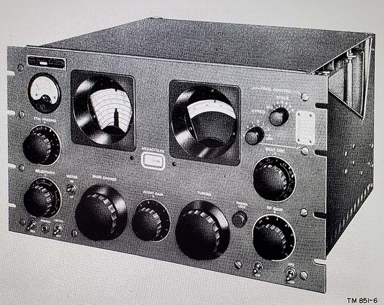
No Receiver is Perfect
- Here are some more details on the "negatives" about the SP-600 receiver. Most are
minor but still should be considered. 1. Limited Dial Resolution - No surprise since each tuning range covers megacycles. Although the resolution is vague, dial accuracy is usually very good with "marker frequencies" generally being right on the pointer-index. 2. No Crystal Calibrator - Since the relationship of the dial index pointer to the tuning dial can't be changed, a crystal calibrator would be of very little benefit. Hammarlund assumed that the receiver would be used by the military or commercial users and a heterodyne frequency meter would be used if accurate frequency setup was necessary. 3. No Antenna Trimmer - The antenna input is designed for a balanced line of 95Z ohms nominal. Hammarlund expected that impedance-matched balanced antennas (dipoles, or similar) would be used. See the next complaint that's related,... 4. Unusual Twin-Ax Antenna Input Connector - These were installed for using balanced 100Z shielded dual conductor cable (called Twin-ax.) The PL-102 connectors aren't difficult to find but it was accepted by Hammarlund that the UG-103/U could be replaced with a SO-239 UHF coax connector in the field (by the end-user.) One of the two wires that went to the two pins of the UG-103/U would be grounded with the remaining wire connected to the center pin of the SO-239 for an unbalanced input suitable for other types of antennas,...verticals, for example. Most users nowadays just make the proper connection inside the PL-102 with a RG-58 coaxial cable extension with a PL-259 on the opposite end. NOTE: The Twin-ax type of coaxial cable has very high capacitance per foot losses that increase substantially as the frequency increases. This high-loss limited the usefulness of this type of cable for antenna feedline purposes. 5. Frequency Drift - Typical of ALL Hammarlund oscillator designs, the HFO and the BFO tend to drift quite a bit. I don't know if they really ever settle down but after 30 minutes of warm up, the frequency drifting is about as good as it's going to get. Certainly the military use involving RTTY mandated employing the JX option for crystal-control of the HFO but Hammarlund assumed that the lower frequency of the BFO operation would be stable enough. Some of the post-WWII Signal Corps BC-794 modifications to "JX" control did also involve a crystal-controlled BFO since these receivers were specifically for RTTY. For typical ham operations, especially in a vintage equipment station, the SP-600 frequency drifting is not noticeable on AM signals and, after 30 minutes warm up, SSB and CW signals are also more or less stable enough. 6. Rapid Tuning Rate - The SP-600 tuning ranges cover wide sections of the spectrum. Good for surveillance or quick checks on known stations. Amateur CW and SSB signals, especially when tuning above 10mc, can be difficult to tune in due to this rapid tuning rate. Often, one gets close with the tuning and then does a fine adjustment using the BFO. Of course, this isn't as noticeable on AM signals. The very large tuning knob does help a lot. 7. Crystal Filter Easily Misaligned - The Crystal Filter requires careful set up for it to work correctly. The position of the PHASING knob is critical to the Crystal Filter's proper and expected operation. Because of the ease at which the Crystal Filter can become mis-aligned, it has gained a reputation of "not working very well." When set up correctly, the Crystal Filter will operate like a typical crystal filter. 8. Selectivity Switch Problems - For some reason the Selectivity switch always seems to have contact problems with switching noise being the symptom. Frequent cleaning with DeOxit will help. 9. Audio Bandwidth and Output Z - The audio is "communications grade" with the -3db roll-offs at 125hz and 4500hz and a "flat response" from 200hz to 2500hz. When selecting 13kc IF bandwidth, the increased higher audio frequencies tend to make the audio response sound thin without much bass. Better overall audio response for typical AM stations will be experienced in the 8kc bandwidth, or even in the 3kc bandwidth for a very mellow sound. It does depend on the quality of loudspeaker system used and where the loudspeaker is located. The audio output impedance of 600Z ohms requires a matching transformer and the quality and design of the matching transformer also can affect the low-end audio. 10. Size, Weight and Cabinets - The SP-600 is a physically large receiver that takes up a lot of bench space. Install the receiver into a cabinet and it's even bigger. Then there's the carrying handles on the sides of the cabinet that always seem to limit what's put next to the receiver. Weight of the chassis is 65 pounds but put that into the Hammarlund cabinet and the weight goes up to 92 pounds. Genuine Hammarlund Series 600 cabinets are moderately difficult to find. 11. A Final Note - So, are these serious enough operational issues that the SP-600 wouldn't be considered as THE station receiver in a vintage ham station set up? I think the SP-600 can perform quite well but there are a few things that can affect the enjoyment of using this receiver. Size and weight might be one issue. It's difficult to integrate such a large receiver onto a desk top with other equipment. Another perceived problem is limited dial resolution making "to the kilocycle" tuning is impossible. Then there's the problematic audio reproduction that might affect the enjoyment of AM signals. I think another important issue would be the difficulty in rebuilding an early SP-600 and, even after that formidable task is finished, then there's the "all important" proper and correct alignment. A careful and accurate alignment WILL make ALL the difference in whether the SP-600 attains an acceptable performance level or not. It's difficult to find one really important issue that makes the SP-600 undesirable as THE station receiver. Who knows? Maybe it's the SP-600's unique "dual portholes" appearance. When considering the SP-600 as a vintage ham station receiver, try to remember that the receiver was designed over 75 years ago. The receiver was at the upper end of top-performers in 1950, when it was introduced. The SP-600 was a competitive receiver at that time but it can't compete with 75 years of receiver design and electronics evolution. When listening to an AM signal using the SP-600, be sure to take into consideration that the receiver was originally intended for surveillance and data reception by the military,...not as a listening-pleasure band-cruiser. |
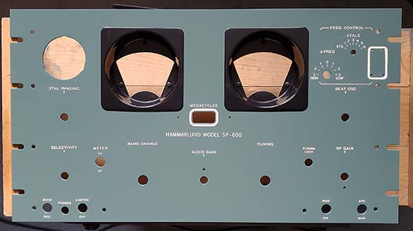
Collectors Photo Gallery of SP-600 Receivers |
|
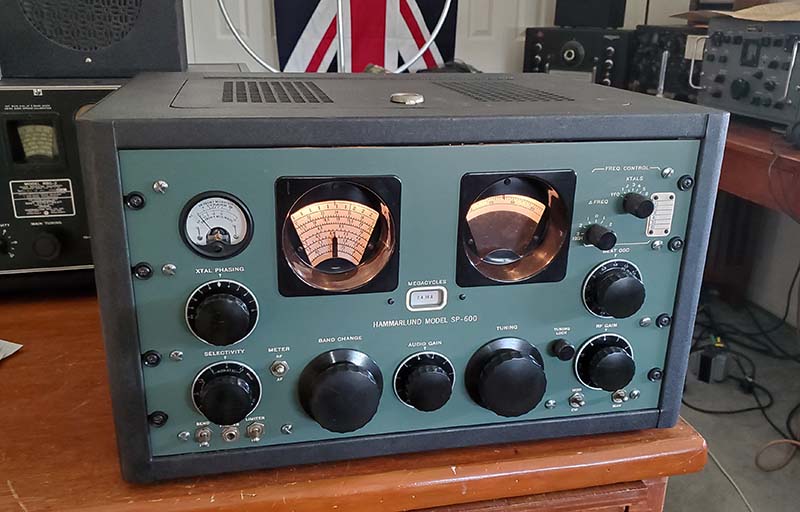
SP-600 JX from the RCA David Sarnoff Research Center
|
|
SP-600 JX-14
|
|
SP-600 JX Though this SP-600 is in fairly rough condition one
can't help noticing that the front panel has been painted light blue and
the dial escutcheons painted dark blue. Obviously, when doing an
end-user repaint,...anything goes. With the white cabinet, this was
probably a visually striking SP-600 after it had just been repainted. |
|
SP-600 JX-17 SP-600 JX-17, standard configuration. The JX-17 was probably the most produced version of the SP-600. It was designed specifically for diversity operation and has a slightly different AVC system because of that. The red knobs are specifically for diversity operation options and are only found on the JX-17 version. Since the JX-17 was for diversity set-ups, a remote relay socket isn't provided on the rear chassis. The cabinet shown in this photograph has been repainted to a cream-color.
Photo from eBay. |
|
SP-600 JX-17 Console Here is a SP-600 JX-17 that is installed into a wooden console made out of plywood that has been stained and finished. The large speaker area is integral to the cabinet and the receiver is mounted from the front into its area. This SP-600 console is in Berlin, Germany and was used by the US Army "Berlin Brigade," possibly at Andrews Army Base where it was placed in the soldier's dayroom as an "entertainment radio." The photo is from Nicolas von Moellendorff, who is the current owner. Nick obtained this SP-600 from the last manager of the US Army Laundry in Berlin. It has a 120vac to 240vac transformer external to the receiver for operation on European line voltage (and interfacing to Euro-plugs and receptacles.) Nick had a small museum in Berlin for US Army items and equipment. He currently has a militaria website. The URL is www.berlin-military.com |
|
SP-600 VLF31 The SP-600-VLF31 receiver tunes from 10kc to 540kc and is built along the lines of the HF SP-600 receiver. The "VLF" is NOT a SP-600 with LF coils installed in the turret. It is a completely different circuit designed specifically for low frequency operation. First, it's a single-conversion superhet that is using 705kc as the IF. It employs two TRF amplifiers in the front end and uses a total of 21 tubes. There's a 1160kc conversion oscillator circuit that mixes with the 705kc IF output to provide a 455kc IF output to run RTTY or similar devices. The Selectable Xtal oscillator has four positions and uses FT-243 crystals. There are only five selectivity positions and all of them go thru the dual stage bandpass and phasing crystal filter. Four IF amplifiers are used. While there are significant differences in the circuit, the construction and most of the mechanics are the same as the HF SP-600. Turret band switching, same dial drive system, similar layout, etc. The side panels are similar to the R-390A receiver and don't have the typical SP-600 "pylons." The chassis and side panels are gold iridite (aka alodine) finish. What about performance? If you're familiar with how vintage, high-performance VLF receivers operate and you are located in a RF-quite area and you're using a good design loop antenna (either remote tuned or shielded magnetic,) the SP-600-VLF-31 is an unbeatable LF receiver. I've logged well-over 250 NDB (Airport Beacons) from all over North America with this receiver operating with a six-foot remotely tuned loop antenna. I used this receiver for a 2XQSO with NO3M in Pennsylvania and WØSD in South Dakota on 630M CW. The SP-600-VLF shown was built in 1958. A lot more detail about this SP-600-VLF31 is in the write-up in "Hammarlund SP-600VLF Receiver" - use the Home-Index to navigate |
SP-600-JX-21 I've owned this receiver for about 16 years and it has undergone several restorations during that time. I bought it from Jack Brower N7ID (now SK) who brought it down to Virginia City from his QTH in south-eastern Idaho in 2008. He enjoyed driving, I guess, because he insisted on delivering the receiver "in person" (maybe he wanted to see the WHRM too.) This receiver was from a humid location or it was stored poorly. I've had to do a lot of rework that involved replacing corroded parts, including replacing the entire SELECTIVITY switch, replacing the tuning and logging dials, replacing the CL meter, replacing a lot of the wiring,...on and on. The first restoration got the receiver working and all of the molded caps replaced. The second restoration was all cosmetic. In 2010, I painted the front panel green but that was quickly changed back to gray. I had the gray front panel paint matched from the SP-600-25C receiver's original paint panel and it's an automotive type acrylic enamel paint. The color seems dark but that's how the original 25C looks. The gloss came from a very slight polishing I did. I also returned the cabinet color to the standard gray (as soon as I installed the new panel color JX-21 into the new gray cabinet I knew "that's a lot of gray!") Later, I replaced the CL meter with a NOS Marion Electric meter (not installed in this photo.) In 2024, I found a good condition spare SP-600 front panel. I painted it sage green and have installed it on this JX-21. Luckily, the spare panel allowed me to save this excellent gray panel,...just in case,...if I want to change back to a gray panel some day, it becomes a relatively easy swap. |
|
WA7YBS 75M & 630M Station The station consists of two Hammarlund SP-600 receivers. The top receiver is the SP-600VLF-31 tuning from 10kc up to 540kc. The bottom receiver is the Hammarlund SP-600 JX-21 tuning from 540kc up to 54mc. The small box to the left of the JX-21 is the remote tuning for the six-foot loop antenna used on 630M for reception. The HF receiver output is to a floor speaker. The LF receiver output is to 600Z ohm 'phones. The transmitter is an ART-13A with O-17/ART-13A LFO installed allowing operation from 200kc up to 600kc. On top of the ART-13A is the CU-32/ART-13A Antenna Loading Coil. The CU-32 allows the ART-13A to match a variety of antenna types on LF. Both the HF output and the LF output from the ART-13A are routed through the CU-32. The output of the CU-32 is connected to the HF antenna when "FIXED ANT" is selected and is routed to the 630M antenna when "TRAILING ANT" is selected. The silver box to the left of the ART-13A is an auxiliary condenser that aids in loading the transmitter on 75M. The J-38 hand key is for LF-CW and the mike is for HF phone. LF transmitting antenna is an end-fed wire 163 feet long. HF antenna is a 135' CF Inv-vee with 96' of ladder line to a Viking KW tuner. Unfortunately, I had to disassemble this station. A new "modern, efficient, modulated" furnace that has a "smart" thermostat doesn't like any type of RF field near it. Especially RF in the MW spectrum. I have to move all 630M operations out to the shop and that hasn't happened yet. |
Conclusion |
More
Information Wanted: I'm looking for the following information.
1. If you have a SP-600 that has a panel painted some color other than Hammarlund gray, send a photo. It's certainly an end-user repaint but vintage repaints are interesting. So far, I've only seen green, blue and khaki. There's a maroon front panel on the Internet. Also, a black panel that might be anodized. Any other colors out there? 2. Does anyone own a SP-600 J-4 or the R-320 version of the SP-600? The receiver has an IF Gain control where the JX option normally is. Used for triple-diversity setup. I've never seen one. 3. Does anyone own a SP-600-JLX? It covers 100kc to 400kc and the HF bands. I've never seen one. For Sending You SP-600 Photos or Other Information - Here's the e-mail link: WHRM - SP600 INFO and, there's more Hammalund info in these articles,... Pre-War Super Pro Receivers
- If you want to know more about how the SP-600 came into being by
reading about its "older brothers," read our article "The Incredible 'Super Pro'
Receivers"
which details each of the early Hammarlund models - the Comet Pro, all of the pre-war Super Pros, the SP-10, the SP-100, the SP-200 and the
post-WWII
SP-400
receivers, along with the WWII Military versions, the Power Supplies plus
lots of other Hammarlund information. Hammarlund's SP-600-VLF Receiver - If you're interested in the VLF version of the SP-600, go to "Hammarlund SP-600-VLF Receiver." If you've found the the VLF's manual is absolutely no help for alignment instructions, this article includes a newly-written procedure for sweep aligning the VLF's IF that's easy to follow and doesn't require any special equipment. Navigation links are in Home/Index for all three articles |
This is the earliest version of the JX-21. The JX-21 was produced mainly for the USAF and there were several orders for these receivers throughout the 1950s. In the late-1960s, the last SP-600 version was released, the JX-21A featuring a product detector, different knob styles and different front panel engraving. |
Henry Rogers WA7YBS © December 11, 2009, more info added January 2010, more info added August 2010, re-edit June 2011, Dial Slippage additions, 630M station addition April 2018, re-edited entire write-up, added a significant amount of new data and returned it to a one-part article Oct 2024, more details added and new URL Nov, 2024, |
|
Radio Boulevard
Western Historic Radio Museum
Vintage Radio Communication Equipment Rebuilding & Restoration Articles,
Vintage Radio History and WHRM Radio Photo Galleries
1909 - 1969
- 60 years of Radio Technology -
This website created and maintained by: Henry Rogers - Radio Boulevard, Western Historic Radio Museum © 1997/2024