Radio Boulevard
Western Historic Radio Museum
 

Rebuilding the BC-348 Family of Receivers
(includes Grid-Cap, Single End & BC-224)

Information in Part 1 - BC-348 History, Missing Parts, Dynamotor Service and Retrofit for Q,N & J Versions

Information in Part 2 - Dynamotor Retrofit for BC-348 Grid Cap Versions, Retrofit for BC-224

Information in Part 3 - Expected Performance, Better AC Power Supplies, Painting Wrinkle Finish

 
by: Henry Rogers WA7YBS/WHRM

PART 3
 

Performance Expectations for the BC-348, both SET and GCT Versions


BC-348-Q with the SAAMA winged decal. SAAMA was the San Antonio Air Materiel Area, part of Kelly Air Force Base in Texas. SAAMA repaired and rebuilt all types of Air Force equipment from radio gear to jet engines. They worked on lots of BC-348s and ART-13s. Most gear that went through the SAAMA depot would be ink-stamped and dated but some, like this BC-348, had a "winged emblem" decal applied. The smaller square decal indicates the receiver audio output is set for low impedance. SAAMA was in operation from 1946 to 1995, ceasing operations when Kelly AFB was closed.

The BC-348 is an amazing receiver and the more you use it, the more you'll appreciate the fact that this great performing receiver "does so much, so well, with so little." Being an aircraft receiver, size and weight had to be kept to a minimum but this little receiver has double preselection (two tuned RF stages,) three IF amplifier stages, a Crystal Filter, a front panel tuned BFO, two different audio output impedances and a "1940s accurate" illuminated dial with direct frequency readout. Unlike many of its contemporaries from WWII, the BC-348 is virtually "self-contained" only requiring the user to connect it to the aircraft battery buss, connect the remote standby line, connect the antenna and plug in the 'phones. No peripheral devices were required for its operation. Given the chance, a competently rebuilt BC-348 that has had a full IF/RF alignment and is operated by an experienced vintage military radio enthusiast will provide solid copy on any of the ham bands that are normally used for amateur vintage military radio nets.

It's surprising that even today the old myths of "not very sensitive" or "broad as a barn" still turn up in contemporary reviews of the BC-348. The receiver's perceived performance deficiencies are directly related the operator's experience with using WWII vintage receivers in contemporary, "on the air" environments and to how thoroughly the receiver was rebuilt and how accurately it was aligned. I've used BC-348 receivers, both SET and GCT types, many times as the station receiver and have found them to be fine, dependable receivers. Can adjacent frequency activity be heard? Usually. But does it prevent solid copy? Of course not. Remember, you have a Crystal Filter! With the Crystal Filter "ON" the IF passband will be around 1KC wide. The Crystal Filter will reduce adjacent frequency interference on AM - just be sure to tune the incoming signal "on the nose." You can be sure that the critics who keep promoting the "broad as a barn" reputation of the BC-348 have never used the Crystal Filter or they have never aligned the IF section of their receiver correctly. Using the Crystal Filter will almost be imperative at some point during a mil-rad net. It isn't always going to be required but, when the adjacent frequency activity comes a little too close, you'll need it and you'll be glad that your receiver's Crystal Filter is working and aligned.

I've used the BC-348 on CW also. It's a very good CW receiver with very little drift. Of course, the lack of CW activity these days doesn't offer up much of a challenge to the BC-348's selectivity. SSB is also demodulated quite well since in MVC the VOLUME is actually the RF Gain control. For SW-BC, the BC-348 will receive stations quite well and even though the audio output was intended for 'phones the original audio output will easily drive a matched loudspeaker quite well. Utilities stations are also easy to receive on many different frequencies.

Not that the BC-348 doesn't have a few minor issues though. As with most vintage receivers, the dial resolution is vague at best. During WWII, if an accurate frequency setting was required then a frequency meter had to be used. Since there's no logging scale on the BC-348 there's no easy way to accurately reset the tuning dial to predetermined frequencies. Resetting desired tuned frequencies will require closely observing and noting the exact dial indication versus the actual tuned frequency or using a heterodyne frequency meter or similar device. Depending on the frequency of operation some dynamotor noise (hash) might be heard. This can be a real problem on the 200-500kc band (630M operation) but the hash usually decreases at higher frequencies. Full shielding on all cables will be necessary for both transmitter and receiver dynamotor cables for quiet operation. There isn't a Noise Limiter circuit, leaving only the Crystal Filter (reducing IF bandwidth) as a noise reduction option. These issues are normally easy to deal with when setting up the station.

For WWII-vintage radio enthusiasts, the BC-348 is a great performer that always delivers solid copy even in tough conditions. The operator must have the desire to use a WWII vintage aircraft receiver in a modern "on the air" environment and should have some experience in using WWII vintage radio gear. This means that the operator must have rebuilt his receiver competently and performed a full IF/RF alignment and the receiver must be integrated into the station properly. Then the operator must employ the QRM reduction methods provided,...the Crystal Filter, "off-frequency tuning," using MVC to reduce QRM and QRN, using a frequency resonant antenna. It takes some practice and some experience but given the time most enthusiasts will find the BC-348 is a very capable receiver. 

Performance Comparisons of Both Versions

GCT versus SET - After working on several receivers from both the SET version and the GCT version it is apparent that each version has its own particular advantages. The advantages are in the mechanical construction and the ease of rework though, not necessarily in performance. The GCT version was expensive to build and difficult to work on due to component boards and wiring harnesses used in its construction. The SET version was designed to be less expensive to build and much easier to work on since the majority of components were mounted in the circuitry rather than on component boards. Mechanically, the GCT versions were a little more stoutly built and have more shielding in the IF/Crystal Filter area and the BFO which, of course, was part of the expense of the design. There's less shielding, or in some cases simple flat metal shields, in the SET versions for the same reasons.

The GCT versions included an ANT. TRIM control that was deleted from the SET versions. The ANT. TRIM would be an advantage when using an end-fed wire antenna that was untuned. Most ham stations though use the transmitting antenna for receive, so they provide a tuned antenna to the receiver and an antenna trim control is not really needed.

Both receiver-types have plenty of audio and easily drive a matched loudspeaker. If you plan on using a stock LS-3 (8K Z,) be sure you have the audio transformer tap connected to the HI-Z terminal. If you've modified an LS-3 to have a 600 ohm Z input then you'll have to connect to the LO-Z terminal on the audio transformer (the same Z caveats apply if you are using a headset instead of a loudspeaker.) Some users believe that there are performance differences when comparing the two versions of the BC-348 but I've found that careful attention to detail when performing the rebuild and, most importantly, a thorough and accurate final alignment, results in either version providing excellent performance. The two BC-348 versions were considered interchangeable by the military and my experience seems to confirm that there is virtually no difference in performance between properly operating receivers of either type. As mentioned above, the main reason that the military and contractors went to the SET version was cost. The cost factor also was applied to any repair work,...the SET is much easier to work on and made it though the depot much faster.


The finished RCA BC-348-C owned by KØDWC


AC Power Supply Enhancement for the BC-348

Although all of the proceeding sections have been about operating the BC-348 on its original dynamotor, for some enthusiasts, DC operation has too many disadvantages. There's no excuse today for hacking-up an original dynamotor-operated BC-348,...they are just too rare for that to even be considered. However since 98% of all BC-348s have already been converted to AC operation, a good candidate for refurbishment is easy to find. Usually all that's necessary for proper operation of the receiver is to rebuild the existing AC power supply to function correctly and then to carefully check out and repair the receiver as needed, then finish up with a full IF/RF alignment. The following section describes how to built a dual section type of AC power supply that will operate the BC-348 "better than" the original dynamotor. Attention to detail and competent workmanship are necessary but the results will be a receiver that operates quietly and does so "to spec."


How to Build (or Rebuild) a "Homebrew" AC Power Supply for Good Filtering - Many users don't want to run their BC-348 on the original dynamotor. Though convenience is certainly a factor, so is the dynamotor noise. The noise from the dynamotor is not the aural experience but rather the dynamotor "hash" that is present even in extremely well-filtered dynamotor circuits. Although for most users the "hash" is barely audible in the receiver in normal mil-rad net operation, if a particular station is extremely weak, the "hash" can affect copy. Today, there's absolutely no excuse for "hacking up" an original dynamotor operated BC-348 just to modify it for AC operation because practically every single BC-348 for sale has already been converted for AC operation. However, most of the AC power supplies that are installed in BC-348s are inadequately filtered and hum is quite audible and sometimes very annoying, especially when using earphones.

There are two methods to achieve good filtering. If a Pi-network is used for the filter, that is, one choke and two electrolytic capacitors, then the value of the capacitors will have to be rather high. Two 40uf electrolyics would be typical for a Pi-network filter. If a dual section filter is used, that is two chokes and three capacitors, then the value of the three electrolyics can be reduced to 10uf each.

In order to have very good filtering, two filter chokes and three filter capacitors should be used. This dual section filter will reduce the hum level to "imperceptible." You might have to replace the power transformer since the extra filter choke will drop the B+ somewhat. Most transformers were providing higher B+ than necessary anyway and the builder used a series load resistor to drop the voltage to about +230vdc. Another trick with two filter chokes is to use "choke input" which eliminates the input filter capacitor. This will drop the B+ significantly but it will improve regulation. With "choke input" the value of the electrolytics should be increased to 20uf. Whether you will be able to use "choke input" will depend on your power transformer's HV winding supplying a high enough AC to the rectifier to compensate for the voltage drop in the filter since the lack of an input capacitor doesn't have the rectifier output "charging to peak." There are many solutions to the filtering problem and the proper B+ voltage.

Remember, the original design of the BC-348 was as a DC operated receiver so filtering was minimal and trying to use just a typical Pi-filter arrangement for the power supply will result in too much audible hum unless a significant increase in the capacitance value is used. Even then, the hum is still present although usually reduced to a level where it isn't too annoying if the volume is kept at a fairly high level.    >>>

>>>   The original design of the BC-348 audio output stage was to ground the cathode and to apply a  negative bias the grid (called "fixed bias.") To achieve the bias voltage the negative from the dynamotor was connected through the choke inside the audio output transformer unit to chassis. The resistance of the choke was about 250 ohms which elevated the dynamotor negative above chassis and provided about minus 16vdc bias voltage. When designing your AC power supply, you will have to connect the CT of the  power transformer to the B- line which then connects to the choke inside the audio output transformer unit. Then, in order to achieve good filtering, the negatives of the filter capacitors should connect to B-, not to chassis. This will provide good filtering for the -16vdc bias voltage and also will result in a power supply that has no perceptible hum. The exception is the last filter capacitor in the dual section filter which should have its negative connected to chassis (but the first and second filter capacitors have their negatives connected to B-.)

When it comes to construction, the main problem is lack of space in the GCT versions since the chassis extends under the dynamotor. This isn't the case with the SET version and removal of C-70 allows plenty of room to fit a well-filtered power supply (although C-70 removal is not recommended.) If C-70 is left in place, the SET version has same space challenges as the GCT version. So, depending on your receiver, fitting a power transformer, two chokes, rectifier tube and three filter capacitors onto a small chassis with no depth available is a challenge. I utilize a small one-half inch tall chassis that just fits into the dynamotor area which mounts using the original dynamotor threaded bosses. This gives much more clearance and allows for mounting larger components underneath without interference from C-70 or from the chassis extension on the GTC versions. If a flat chassis is used then try to avoid using a "tub mount" power transformer if possible (this type of transformer can be mounted on standoffs to gain under-chassis clearance.) Also, when using a flat chassis, if the component height is kept at under 1" there won't be any clearance problems with either type of receiver.

There's really no reason to use a vacuum tube rectifier. Going solid-state certainly will save significant chassis space as you now don't need a tube socket or a rectifier tube. Don't worry about cathode stripping with full B+ appearing on cold tubes. That happens with dynamotor operation, too (as soon as the dynamotor is up to speed, full B+ voltage is present.) Solid State rectifiers will result in higher B+ voltage so be sure to compensate for this in your design. Be sure to prevent magnetic coupling between the "iron" by proper orientation of the transformer and chokes. It's possible to build the AC PS in "two levels" - that is, to use a second chassis over the main chassis to gain more area for components (or two angled brackets might suffice.) Most builders don't consider that there is ample space above the main chassis and a secondary chassis can solve a lot of space problems. You can easily build as high as the top of the side support of the chassis which has clearance to fit into the cabinet.

Dual Section Filtered Power Supply - To the right is the schematic for a dual section filtered power supply that I build and installed into a GTC version BC-348-R SN 10662 Belmont contract. (In fact, I've built two of this design AC PS for the very same Belmont BC-348 but that's a different story that's covered in the section "A New AC Power Supply for the Belmont BC-348" which is the next section following this one.) This receiver had an AC power supply that utilized a Pi-network filter with 10uf filter capacitors. The builder had connected the CT and filter negatives to chassis and connected B- to chassis. This effectively eliminated the filter choke and negative bias from the circuit. Though the hum wasn't excessive, the audio distortion at louder volume was. A redesigned power supply was needed for this otherwise great condition BC-348-R.

Unfortunately, the power transformer HV winding 230-0-230vac and just provided +230vdc B+ using the Pi-network. If I installed a dual section filter, the B+ would probably be around +200vdc or less under load. I had to select a different power transformer, one with 270-0-270vac would be perfect but all I could find in the junk boxes was a 290-0-290vac - close enough!

Since the dual section filter wouldn't drop enough voltage, I had to utilize a series dropping resistor. I calculated the value by assuming the BC-348 B+ current requirement is 60mA. The IR drop was going to be about +60vdc, so the value should be close to 1000 ohms and I²R=P showed that the resistor had to dissipate about 4.0 watts. On the test bench, the power supply B+ was +235vdc when powering the receiver.

I built the power supply onto a small chassis that measured 6.25"W x 3.75"D x 0.625"T (I had a few of these made at a local sheet metal shop.) The height of the chassis just allows the left side receiver to cabinet mounting screw to have clearance over it. The bottom edge of the chassis will have to be "notched" for clearance for the dynamotor mounting bosses (see photo lower right.) Concerning the layout, I find that nearly all old power supplies mounted the power transformer in the left corner of the chassis which presents several problems when one is trying to utilize a terminal strip for connecting the AC PS to the receiver. I find that mounting the power transformer on the right side allows more room underneath for components and tie strips. I also use solid-state diodes for the rectifier to provide more space for important filtering components.

After all of the sheet metal work was finished but before any components were mounted, I like to put a finish on the aluminum so it doesn't look so "homebrew." I clean the chassis, then use 400 grit aluminum oxide paper to impart a slight grain to the surface. Then I heat the chassis using a heat gun until it's fairly warm - about 120 degrees. Then I spray the chassis with Easy-Off Oven Cleaner. The active ingredient in EOOC is Sodium Hydroxide which reacts with the aluminum to create a flat finish. Leave the EOOC on the chassis for about five minutes and then rinse it off with cold water. Don't rub the finish or you'll change it's flat look. Use a heat gun to dry the water off and the finished chassis will look like a professionally made piece. >>>

>>> When mounting the "iron" be sure to avoid any physical orientation that might enhance magnetic coupling between the chokes and the power transformer.

The Dynamotor harness was intact in SN 10662 so I utilized an original terminal strip from a "junk" DM-28 base. This was mounted under the chassis with spacers so it would place the terminal screws at the proper height for the opening in the side panel of the receiver to allow access for connecting and disconnecting the harness.

AC (line - hot) is routed into the SO-143 connector via pins 3 and 4. AC line then goes through the wiring harness utilizing the AVC-MVC switch for "ON/OFF" function (as original) and then to the AC power supply via the dynamotor harness. This routing doesn't add any AC hum to the receiver output. I have tried both a direct AC connection to the power supply and routing through the harness - there is no difference, so no hum is "added" by using the AC connection as shown in the schematic.


photo above: the dual section filtered power supply used in BC-348-R sn 10662. The wire that exits the right side of the chassis is to connect the neutral on the AC line input to pins 7 & 8 on the SO-143 socket. Be sure to disconnect the chassis connection  that was originally present for dynamotor operation.

Be aware that on both the GTC and the Single-ended versions, the dial lights connect to the AVC-MVC switch to provide +28vdc to the lamps but now this point will be at 115vac. You'll have to move the dial lights connection to an adjacent tube socket for the proper 6.3vac. Be sure to verify that +LV and the Blank wires in the harness are connected with +LV being a white with black tracer wire going to the tube heaters and the "blank" position is a plain white wire that goes to the AVC-MVC switch. Sometimes these two wire positions in the harness are reversed since when operating with a dynamotor these two wires are jumped together inside the dynamotor. Also, be sure to check that pins 7 and 8 on the SO-143 are NOT connected to chassis since we are utilizing that connection for AC Neutral. If you want to keep the Remote Standby operational, more than likely you'll have to go back into the BC-348 and find where the two wires for the remote receiver standby line are tied together (they originally were connected to pins 2 and 6 of the SO-143 connector.) Since I utilized the SO-143 connector for AC power input, I also can access the remote standby line for the receiver from there. Check the section in Part One about the PL-103 connector connections or on how to input the wires using push-on connectors the just fit the blade contacts of the SO-143 connector if you're not using the PL-103. The push-on connectors makes for a very clean hook-up for the BC-348 if a PL-103 isn't available.


photo above: The underneath of the power supply for sn 10662 showing how compact the circuit can be using SS rectifiers. Also note the original dynamotor terminal strip used for the connections.

Another Problem - Upon power up the BC-348-R operated fine. I measured the B+ at +235vdc which is just where it should be. After the receiver had operated for a while I tuned around the 40M band and noted that I had difficulty tuning in SSB signals. This isn't usually the case with BC-348 receivers. There was a large amount of backlash in the tuning. Looking at the tuning condenser drive gear I noted that there was no "anti-backlash" set into the mesh with the straight-tooth drive gear from the gear train. Luckily, it's easy to set this anti-backlash. First set the tuning condenser for "full mesh." Then loosened the two front mounting screws on the tuning condenser. Then slightly lift the front of the tuning condenser and the condenser drive gear will disengage from the small straight-tooth drive gear. Now while holding the front gear move the back gear to set in about "two teeth" of anti-backlash and hold this tightly with you fingers while re-engaging the anti-backlash gear into the straight-tooth gear. Then re-tighten the condenser mounting screws. This cleared up the tuning problem.
 

photo left: BC-348-R SN: 10662 Belmont Radio contract from 1942. This shows the final installation of the dual section filter AC power supply. This receiver was in very nice physical condition and the original modification to AC operation didn't do any damage. There were some design issues with the original mod AC PS so I built this new AC power supply as part of the restoration of this receiver. Final operation of this receiver is impressive and the hum level is entirely imperceptible.

A New AC Power Supply for Belmont BC-348-R SN:10662 - Nov 26, 2021


What Happened to the First Power Supply? - The original AC PS that I built for SN:10662 (that's described above) was an early-2012 project. It was only installed in the Belmont '348 for a relatively short time because, about a year later, a mil-rad collector friend of mine was going though the "trials" of trying to design and build a new AC power supply for his BC-348-Q receiver. After many telephone calls that essentially went over the same things time after time, I traded the guy an already built and working AC power supply - the one that was in SN:10662 - for a nice condition BC-344-D. That solved his problem but the Belmont ended up being stored in the closet in my upstairs ham shack without a power supply for almost nine years. Though I have a working BC-224 and a working BC-348-Q both of these receivers are dynamotor operated. I wanted to pair an AC operated BC-348 with an AC operated ART-13A transmitter - sort of a "pseudo" ARC-8 station. Although the purist might opt for DC operation of the ARC-8 station, for Mil-Rad Net operations, the dynamotor for the BC-348 would be running for the entire net and the ART-13 dynamotor would "turn on" with each transmission made. The required PP-1104C 50A power supply for the dynamotors would also be running continuously during the net operations (PP-1104s are noisy.) AC operation for the "long hours" of a Mil-Rad Net is much easier on the ears and on the equipment.

Parts Round-up - The only '348 I had that was close to operating condition was the primo-condition Belmont that I had restored but was now just minus an AC power supply. It was extracted from the closet and put on the bench. I had an old AC PS stripped chassis out of a "junker" '348 to start with (it was actually a flat piece of .090" aluminum.) I needed a power transformer - no problem, I must have at least 100 parts transformers out in the shop. Two chokes, some capacitors and a couple of 1N4007 diodes were also "junk box stock" items. The chassis that I was using already had the dynamotor terminal strip mounted.

The Build - I had a nice hermetically-sealed transformer that had a 6.5 vac 4 amp tube heater winding and a 225-0-225vac HV winding. No rectifier winding on the transformer and none needed. To allow the installation of two chokes in such a limited space was going to require a vertical mounting. Two suitable steel brackets were found in the junk boxes. Height of the bracket-choke assembly has to be 3.5" so it doesn't exceed the height of the side rails (slightly over 4".) Using the brackets, I could mount one choke vertically on the chassis and one horizontally on the brackets with a total height of 3.5". Also, the brackets allow orienting the chokes so their windings can't couple magnetically. A dual choke in one housing would have been a much neater solution but I couldn't find one that had the choke specs needed for the PS requirements.

All filter capacitors and the two 1N4007 diodes were mounted under the chassis. The height of the components mounted under the chassis can't exceed the height of the dynamotor terminal strip. There are a few screws that project up through the dynamotor bay bottom plate which can also interfere with the PS components. If you maintain < 1" of height on the components underneath the chassis there shouldn't be any interference. Since I was duplicating the old AC PS, I used the same schematic shown above resulting the a similar component layout underneath. The only significant differences were the "stacked" orientation of the filter chokes and the "flat sheet metal chassis."


The photo above shows the AC power supply installed in the Belmont BC-348-R. Notice that the lower choke is mounted to the chassis in a normal manner. The upper choke is mounted using two steel brackets that have the highest part of this choke just slightly lower than the top of the power transformer and both units are about .250" lower than the side rail. Note the twisted wires from the upper choke are routed through a grommet lined hole in the chassis along with the wires from the bottom choke. The four chassis mounting screws thread into bosses that increase the height of the chassis off of the receiver's cast chassis frame. The bosses add about .125" to the clearance available in the dynamotor bay.

Pre-test and Installation - Once the PS was built, then using clip leads, I powered it up using a Powerstat to see how the voltages looked. I had calculated a load at around 3.3K 15W to draw 70mA at about +230vdc. I had +265vdc with the AC input at 120vac. Value of R1 calculated at about 485 ohms and about 2.5W of dissipation. I installed two 1K 5W WW in parallel for 500 ohms at 10W. Under load the PS output was +235vdc at 70mA. Next was the physical installation.

The PS chassis mounts with 8-32 screws. The neutral wire is routed thru a gap in the corner of the dynamotor bay and it exits just behind the SO-143 connector. The neutral wire was soldered to pin 7/8 on SO-143. The five wires of the dynamotor harness were connected to the proper terminals on the PS (-LV, +LV, AC, -HV, +HV.) A clip lead jumper was installed on pins 2 & 6 for remote standby. I connected the AC to pins 7/8 and pins 3/4 and applied power using the Powerstat. The BC-348 came on in about 20 seconds. I only had a ten foot wire for the antenna so only AM-BC stations were heard (AM-BC stations above 1500kc.) I connected the station antenna and copied several 80M hams so operation seemed normal. I measured the +HV at +235vdc between +HV and -HV and about +219vdc between +HV and chassis which means there's about -16vdc grid bias and that's about correct.

Since this was the second AC power supply built, the Belmont already had all of the wiring present for installing this new PS that was essentially just like the one I had traded away. Now I needed the shock mount. I had a FT-154 on the Belmont at one time but, when I pulled it out of the closet,...no shock mount. I believe that I harvested that shock mount for the BC-224 receiver. Anyway, in the parts storage, I found a nice condition Belmont FT-154 shock mount, with the PL-103 still mounted. It needed some clean up and the PL-103 had to be wired for AC operation. Luckily, the PL-103 had the right-angle exit tube for the AC cable and remote standby wiring.

Shown in the photo to the right is Belmont BC-348-R SN:10662 installed in the "pseudo ARC-8" station with the ART-13A below the receiver. The station to the left is the Navy RU-16 & GF-11 Station from the early part of WWII (the contract date is actually from before WWII.) While the ARC-8 station runs on the AC line, the RU-16/GF-11 station runs on +14vdc to operate the common (to both receiver and transmitter) dynamotor. Both stations are fully functional and "on the air" on the West Coast Mil-Rad Nets on 75M.

Here's another way to provide good filtering...

Choke Input Filtered Power Supply - The schematic shown to the left is an AC PS that I installed in BC-348-Q SN 20966, the receiver I wanted to use with my ART-13 transmitter. Since the ART-13 operated on an AC PS, I didn't want the receiver to be dynamotor operated. I naturally used a BC-348 that had years before been AC converted and then just restored the receiver to be as original as possible but with just a well-filtered AC PS installed. This will provide me with a BC-348-Q that is very quite to use and still performs almost exactly like the original dynamotor operated receiver. 

Note that choke input is used. This was because the power transformer had an HV winding that provided about +300vdc with a dual section filter. An easy correction was to go with the choke input which gave about +230vdc output with good filtering characteristics. I did utilize the SO-143 connector for my AC input. Especially important to note is that the negative connection on the first filter capacitor is connected to B- and not to chassis. Most choke input power supplies are not designed to develop a negative bias and the transformer CT and the filter capacitor negative are connected to chassis. However, the BC-348 requires a bias voltage for the audio output tube and this is accomplished by floating the CT or B- and connecting to chassis through a choke with 250 ohms of DCR. To achieve the proper charging loop, the first filter capacitor must be connected to B- to provide good filtering. The second filter capacitor should be connected to chassis though. The second filter capacitor is a 10uf because C-70A/B (in the BC-348) adds a 6uf filter capacitor in parallel, so the total capacitance is 16uf. This type of "hook-up" using a choke input dual section filter reduces the hum to the "imperceptible level."

The Dynamotor harness was intact in SN 20966, so I installed a screw terminal strip underneath the power supply chassis to preserve this hook up method just in case a DM-28 turns up in the future. AC input is through the SO-143 connector pin 3/4 which is the +28vdc input (with the AC neutral wired direct as shown in the schematic.) The wire from Pin 3/4 is routed in the harness to the AVC/MVC switch and then continues as a "switched" +28vdc wire to the Dynamotor harness connection pin 3. Routing the AC input via this wire will add no hum to the audio output.

Shown to the left is the restored BC-348-Q SN 20966. It's hard to believe that it's the same receiver shown in the first section of this article, "Finding a Good Candidate for Restoration." As can be seen, the front panel is original with the "M1" stamp and the very faint "AN - Army-Navy" stamp (just below "BAND SWITCH.") This receiver's front panel was given the same treatment described above using Glass Plus worked with a soft brass brush followed by a heavy application of Armor-All.

photo left: Top of SN 20966 showing the installation of the AC power supply with a dual section filter and solid state rectifiers. Care has to be taken to assure that the long screw on the left side (that secures the radio to the cabinet) will have clearance past the chokes when the AC power supply is installed. The screw is not installed in this photo but it does have the necessary clearance.


photo right:
Close-up of the under side of the AC power supply showing how little space is necessary when using SS rectifiers. The terminal strip allows using the original Dynamotor harness for the hook up. Note the C-70 had to be dismounted to reveal the under side of the AC power supply for the photograph.

Cleaning and Restoration of the Black Wrinkle Finish - To thoroughly clean the wrinkle finish paint I use Glass Plus and a soft brass brush. It sounds harsh but the wrinkle finish can take the abuse. I first remove the knobs and access cover. Then I saturate the front panel with Glass Plus and gently work the solution with a medium soft brass brush - "tooth brush size." I wipe the dirty solution off with paper towels and repeat the process a second time. This time the paper towels should be fairly clean after wiping off the Glass Plus. Any touch-up painting should be done now. I then let the front panel dry thoroughly. Then I apply Armor-All in a very heavy coating and let it set on the front panel for about thirty minutes. After a wipe-down, the panel should look fabulous (for an original.) The same process is applied to the knobs and the access panel. Be careful of any acceptance stamps as this orange ink is somewhat soluble in water or Glass Plus.    I don't use Armor-All anymore. I now use "3 and 1" oil applied with a clean cloth. Wipe off excess with another clean cloth. The results are as good or better than Armor-All and the finish isn't "slippery" like Armor-All is.


photo right: BC-348-R SN:10662 showing the exterior after cleaning and restoration of the original finish

Repainting the BC-348 or BC-224 - All Versions

First off,...don't attempt this unless your receiver is in really, really poor cosmetic condition because IT'S A LOT OF WORK! However, some BC-348s are poor on the outside and really nice on the inside, so a repaint is sometimes a necessity.

You're going to need about two or three cans of VHT High-Temp Black Wrinkle Finish Paint. It is carried at most O'Reilly auto parts stores (also Summit Racing.) Be prepared, it's expensive at around eleven dollars per can. Use a "spray can handle" as this allows better control over the spray pattern. Also, use high quality paint stripper. Remove all of the knobs, the handles, the small panel, the dial cover and the phone jack "toilet-seat" covers. Unsolder the wires to the dial lamps and to the Antenna terminal. Remove the front panel. Keep all of the screws together because they will also be painted. Drill out the rivets that mount the ID tag to the front panel. You will also have to drill out the rivets that hold the two dial lamp sockets to the panel. You can now strip the paint from the front panel, the handles, the knobs and the smaller access panel.

The front panel, all knobs, the two pieces to the dial cover, the phone jack toilet seat covers and the small access panel are to be painted black wrinkle finish. The handles and the screw heads will be painted black satin finish. Some of the original hardware was actually a dark bronze finish but this was an oxide finish that is difficult to accomplish (it's called Brown Patina and will work on brass hardware but not steel.) Sometimes the brown finish can be duplicated with ink dyes that combine brown and black to achieve the proper color. Some restorers just paint the screw heads satin black but this is just a "short cut" that shows a lack of commitment to originality.

First, though, a word or two on how to successfully paint wrinkle finish paint. The original paint used on the BC-348 and all military and commercial gear from the fifties on back was a two-part process that required a base coat of nitrocellulose lacquer that was allowed to dry. Then a catalyst was sprayed onto the lacquer base. The panels were then put into ovens that baked the paint and the wrinkle developed in the oven. That's why most vintage wrinkle paint jobs have the wrinkle on the outside and smooth gloss black paint on the inside. The inside wasn't sprayed with the catalyst.

Today, we use paint that is a one-part process that is heat activated. I do all of my painting outside so the heat comes from incandescent lamps. First, DO NOT pre-heat the metal to be painted by putting in out in the sunlight or in an oven. This causes activation of the wrinkle almost immediately when the paint hits the hot surface and will result in very uneven coverage and spotty wrinkling. Leave the metal at room temperature. Next, the paint has to be applied with very heavy successive coats separated by just a few minutes. I use a minimum of three heavy coats applied at different angles for each coat and separate each application by a couple of minutes. Next, to apply heat I use 100 watt light bulbs in clip-on utility lamps with aluminum shades. These are available at Home Depot for less than $10 each. I usually use three lamps suspended over the panel about 10" to 12" above the panel. The three lamps will heat the paint and the panel and the wrinkle process will start in about 10 minutes. I now use two 250W brood lamps for heat. The two lamps provide more heat that the three 100W lamps and are easier to place correctly. I standby with a hand-held heat gun and after about 10 minutes, when the wrinkling starts, I use the heat gun to apply more heat around the corners and places where the lamps don't heat the panel very well - I still do this and have found it a "necessary" part of the wrinkling process. For stubborn areas, the heat gun will force the wrinkle but don't apply too much heat or the paint will "gloss" and the wrinkle won't match. After about another 5 to 10 minutes the wrinkling should be complete and now remove all heat and let the panel cool down for about 30 minutes. When the panel is cool, the paint will be set-up enough to handle. Let the paint cure at least overnight before mounting any screws or parts to the panel. If you can wait a little longer, like a week, the paint will be much harder and resistant to scratching or other types of damage. Thirty days are required for full curing and after one year the paint is virtually indestructible.

Now comes the tedious part. You'll notice that the silver nomenclature on an original front panel is bare aluminum. Originally, after the panel was painted the paint over the nomenclature was "ground off." Originally, the nomenclature was much higher and when just "ground" down slightly, the bare metal showed through as silver lettering. This time we can't do that since the lettering was already ground down once and now the lettering is just above the paint level. I make a small tool that consists of a small piece of an industrial razor blade piece about .25" wide that is mounted to a small wooden handle. With this tool I can carefully "shave" the wrinkle finish paint off of the nomenclature but the lettering still isn't bright.   

I also make another tool that is another small wooden handle that has the end cut at an angle that has a flat surface. I use 400 grit aluminum oxide paper held to the angled part of the handle with tape to polish the lettering. This leaves the lettering looking very bright and original. Sometimes there might be a minor slip-up but I use a small paint brush to apply Artist's Acrylic Mars Black paint to touch-up scratches or other blemishes I've caused during the process.    >>>

>>>  To remount the ID tag, you'll have to make "fake rivets." I use 4-40 SS (stainless steel) binder head slotted screws. I chuck them up in a drill press and file the head until you don't see the slot but there is still material left to shape a rivet head. Don't use philips head screws because the slots are too deep. After you have four good looking "fake rivets" mount the tag and secure the "fake rivets" using 4-40 nuts on the back of the panel. There is plenty of clearance for the nuts but don't use overly long screws. Although you don't have to make "fake rivets" to remount the dial lamp sockets be VERY CAREFUL about the back clearance when remounting them with screws and nuts. Mount the binder head screws on the back side of the panel and use the nuts on the dial lamp socket side. You still might have to file the head of the screws to be sure you have clearance. The distance between the back of the front panel and the tuning dial mask is minimal. Without the clearance, you'll scratch the dial mask the first time you change bands. Make sure you have the clearance. Nowadays, I'd use the correct rivets - they are easily available on eBay including the rivet setting tool.

Next, paint the knobs and the other parts that should be black wrinkle. Use a small scraper made out of a jeweler's file to remove the paint from the "arrows" on the knobs. An Ex-acto knife with the proper blade can also be used to remove the paint from the "arrow." Some versions of the knobs appear that the arrow was engraved and some version appear to be stamped into the wrinkle finish paint. The engraved arrows clean out fine but the stamped arrows don't. Some vintage drawings/photos show the knobs without any arrows. If you have the stamped type arrows and are having trouble getting them to look correct, it is acceptable to just leave the knobs black wrinkle and not bother trying to scrape out the paint. Also, be sure to paint the handles satin black but the screw heads should be dark-bronze finish.

For the cabinet, I've had pretty good luck just shooting over lightly sanded and very clean original paint with the VHT wrinkle finish and then giving it the heat treatment. You might have to paint one side at a time depending on your heat lamps. I usually do one side at a time because I have better control of the wrinkle process that way. I also use a handheld heat gun to apply heat to corners and edges that the lamps don't heat enough. I have stripped the cabinets and wrinkle finished and I suppose they look slightly better but it's very hard to tell whether a repainted cabinet has been stripped or just painted over.

What about the Signal Corps acceptance stamps? - Without a doubt, the repainted BC-348 looks incomplete without the orange Signal Corps acceptance stamps. What I do is first make full scale drawings of what the typical acceptance stamp looks like. This will have the square boarder with "SC" at the top, a random number that was the inspector's identification and then an "A" at the bottom. Also, make another scale drawing of the "M1" stamp that is on 90% of the BC-348s (MWO for Lo-Z audio output.) I then take the scale drawings to a stationary office supply type store that makes rubber stamps. It costs about $15 to $20 per stamp. Usually the square boarder on the "SC" stamp costs a little more but you "gotta have it." Once you get the rubber stamps, now you can apply your own acceptance stamps on any of your repainted AAF gear. I use Artist's Acrylic to mix up the proper orange color and use water to thin the paint to a very wet mix. I then soak a cloth pad with the orange paint to create an "ink pad." Be sure to practice on some scrap pieces for a while. Also, be sure to have the stamp "runny looking" and be sure to remember - none of the original stampings were straight. After all, the inspectors were just stamping gear they had tested or accepted - it wasn't anything special to them. The "M1" stamp is usually a lighter, almost yellow-orange color ink and done the same way as the "SC" stamp. In fact, the "M1" stamps are usually even "runnier" looking. The "sloppier" the stampings looks, the more original they look.


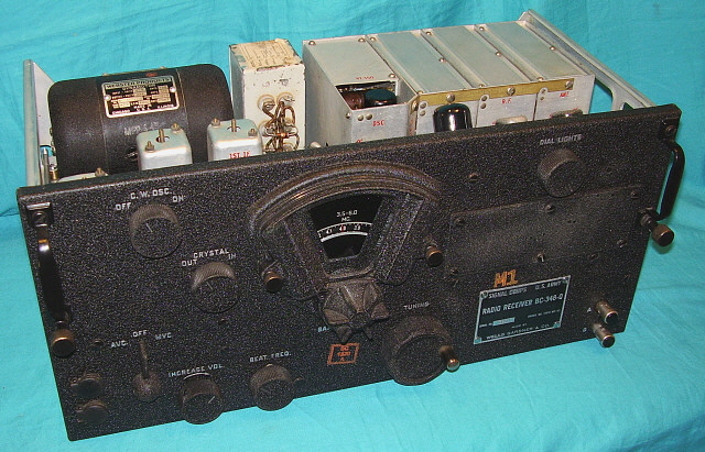
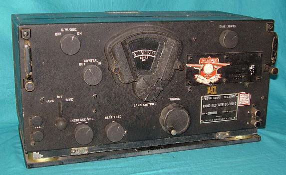
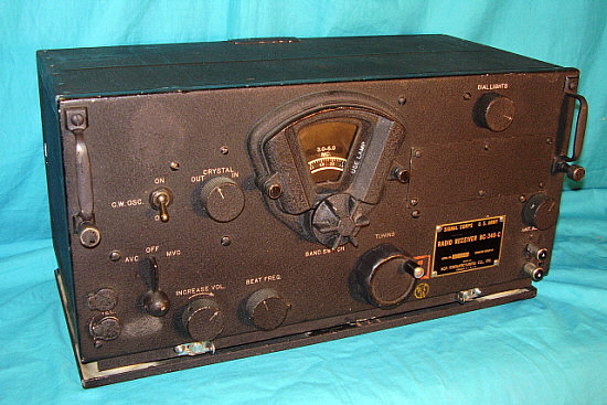
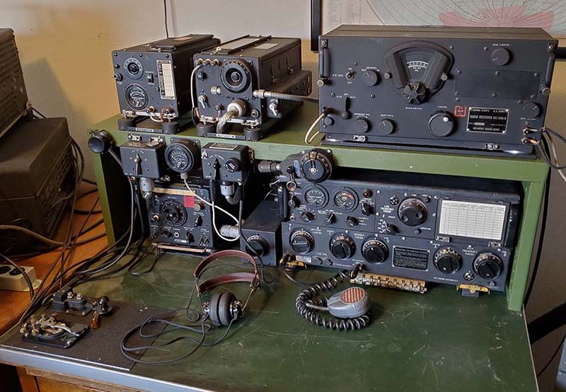
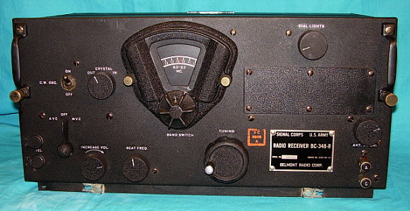
Take a look at BC-348-Q SN 11227 above. This BC-348 has been repainted as described in this section (with the exception that I used Krylon BWF paint instead of VHT.) Also, the Signal Corps acceptance stamps are made with reproduction stamps. Overall, the impression of SN 11227 is that it is an excellent condition, original BC-348. This is the effect we want to achieve in our restorations.

 
References:

1. Various Military Manuals - These are usually the best sources for wiring diagrams, schematics, parts lists and other information that helps to figure out what is "original" for a particular receiver.

2. CQ Surplus Military Radio Conversion Books - Although I knock CQ quite a bit for their conversion and modification publications, their books specifically on the Military Surplus Radio subjects do provide a lot of information on the equipment and may actually provide some insight into how a specific piece of equipment was modified by a former owner.

3. Internet - The Internet is filled with information on BC-348s. Just do a search and see.

Henry Rogers WA7YBS/WHRM ©  JAN 2010, DEC 2010, re-edited to add the following: Grid Capped Tubes Version (Part Two,) Repainting, AC PS © JAN 2011

 Added details on AC conversions related to +LV, tube heaters, AVC-MVC switch connections - NOV 2014

BC-224 info and DM-24 info added - August 2015,... 

added Belmont SN10662 gets a new AC power supply - Dec 2021  -  added BC-348-Q with SAAMA decal photo - Dec 2021  


BC-348 Part 1                       BC-348 Part 2                       Return to Home Index


Radio Boulevard
Western Historic Radio Museum

 Vintage Radio Communication Equipment Rebuilding & Restoration Articles,

 Vintage Radio History and WHRM Radio Photo Galleries

1909 - 1969

- 60 years of Radio Technology -


This website created and maintained by: Henry Rogers - Radio Boulevard, Western Historic Radio Museum © 1997/2023